

Page 1

ISI
A LEAR SIEGLER COMPANY
PUBLIC ADDRESS
AMPLIFIERS Models C10B&C20B
DESCRIPTION
The Bogen Mudels ClOB iuiU C20B sulid-stale public address
amplifiers are rated at 10 watts and 20 watts, respectively, and
are UL and CSA listed.
The units will accommodate most microphone types, offering
the capability for both high impedance and low impedance
microphones. A front panel selector switch allows one of the two
microphone channels (MIC 2) to be used as an auxiliary input,
which can be muted when a customer-supplied SPST normally-
opcii switch is used foi [iiiciuphuiic precedence.
Independent volume controls and a treble control, for adjust
ment of tonal balance, are provided.
Balanced or unbalanced outputs are provided for 4, 8, and 16
ohm speakers, and 25 volt constanl-vollage systems. A terminal
strip with screw terminals allows convenient connection of
speakers, except 70 volt. For 70 volt operation, a quick-disconnect
speaker socket is provided.
The ClOB and C20B amplifiers operate from a 120 volt, 60 Hz
source and have a maximum power consumption of 46 and 60
watts, respectively. A thermostat, enclosed in the power trans
former, protects the unit against overloads.
TECHNICAL SPECIFICATIONS
ClOB
POWER OUTPUT:
FREQUENCY RESPONSE:
HUM AND NOISE:
(20 - 20kHz)
SENSITIVITY:
OUTPUTS:
OUTPUT CONNECTIONS:
INPUT CONNECTIONS:
CONTROLS
TONE CONTROL ACTION
POWER REQUIREMENTS
SEMICONDUCTORS
DIMENSIONS
WEIGHT
10 watts
4, 8, 16 ohms
25V (62.5 ohms)
70V (500 ohms)
Screw-type terminals for 4, 8, 16 ohm and 25V tap
2 MIC HI-Z jacks/2 MIC LO-Z terminals, AUX HI-Z jack,
120 VAC 60 Hz
46 watts
5 lbs. (2.27 kg) 6 lbs. (2.7 kg)
INSTALLATION
UNPACKING
The amplifier was carefully checked before leaving the factory.
Inspect shipping container and unit carefully for indication of
improper handling: if the unit has been damaged, make an
immediate claim to distributor from whom it was purchased, or if
the amplifier was shipped directly to you, notify the carrier without
delay and place your claim.
POWER AND GROUNDING
The ac line cord has a three-prong plug which should be
plugged Into a three-wire grounded, 120 volt, 60 Hz outlet. Since it
is important to ground the amplifier, where a three-wire outlet is
not available, use an adapter (e.g., Levitón No. 5017) and connect
the grounding pigtail to the screw securing the wall plate. If the
wall plate screw is not grounded, connect a wire from the GND
terminal of the amplifier to a water or steam pipe.
C20B
20 watts
80 to 10,000 Hz ±2dB
MIC Input SSdB below rated output
AUX Input 70dB below rated output
MIC HI-Z Input 3mV
MIC LO-Z Input 300/iV
AUX Input 250mV
4, 8, 16 ohms
25V (31.3 ohms)
70V (250 ohms)
Quick-disconnect socket for 70V tap
500/600 line with WMT-1 accessory*
MIC 1, MIC 2/AUX, Treble control
Treble: lOkHz-lldB
120 VAC 60 Hz
60 watts
All Silicon — 11 Transistors, 5 Diodes
1 iys"W X 276"H X 7y"D (28,9 x 7,3 x 19.7 cm)
‘MIC 2/AUX are switch-selectable.
Page 2
AUXILIARY POWER
S-X The auxiliary power receptacle on the rear chassis is a three-wire
grounded outlet, which can supply power to accessory or associated
equipment in the sound system. Be sure that the auxiliary
component does not draw more than 300 watts. The power switch
on the front panel of the amplifierdoes not control this receptacle.
Equipment connected to this receptacle will remain on at all times
unless turned off with its own On/Off switch.
Associated equipment connected to the auxiliary receptacle
with a three-prong line cord will be grounded, providing the
amplifier line cord has been properly grounded, as previously
described. Otherwise, it may be necessary to ground the auxiliary
equipment.
INPUT CONNECTIONS
AMPLIFIER I
6ND COM 16 JL
A74-2090-0I
AMPLIFIER 2
6ND COM t6.TL
ClOB
MICROPHONE: Connect low impedance microphones to the
input screw terminals on the rear panel. High impedance
microphones should be connected to the input jacks provided.
MICROPHONE PRECEDENCE; A built-in circuit provides
muting over the MIC 2/AUX channel. This is achieved by
connecting a customer-supplied SPST normally-open switched
microphone cable to the MIC 2/ AUX MUTE screw terminals.
AUX: To connect a turntable (with ceramic cartridge) to the AUX
jack, use a single-conductor shielded cable terminated in a
standard RCA phono plug. It is recommended that a separate
ground wire be connected between the turntable base and the
amplifier GND terminal to minimize hum pick-up.
The AUX input may also be used for any other signal source
having a high level (.15V) output, such as the Bogen Model
TP50 FM/AM Tuner.
Connecting Low-Impedance Unbalanced Microphone Inputs
-A
-----
-R-
®
\J ^è—3_
MIC z
MIC
AMPLIFIER I
GND COM 0il
Figure 2 — Connecting Amplifiers in Series
AMPLIFIER 2
GNO COM 8A
OUTPUT CONNECTIONS
SPEAKERS: The amplifier may be used with speaker systems
rated at 4, 8 and 16 ohms and with 25-volt and 70-volt constant
voltage systems. For detailed information on the installation of
multiple speaker systems, refer to the Speaker Installation
Instructions (No 54-5001).
Connect the speaker system directly to the speaker output
terminals on the rear of the amplifier. Connect one speaker lead to
the COM terminal and the other to the terminal corresponding to
the impedance of the speaker system For balanced output lines,
remove the link between COM and GND output terminals. If the
line is shielded, connect the shield to GND. The 70V output is
available only through the 3-pin connectors.
Connecting High-Impedance Microphone Inputs
HI-* MIC
BOGEN PL-I /
SWITCHCRAFT WO. 445
A7+-4.1SS -01
Figure 1 — Comiecting Microphone Cables
„
_______
□)
To minimize shock hazard. Class 1 wiring as
Caution
defined in iocai building codes should be used
for 70-volt outputs. Ml other outputs may use
Class 2 wiring.
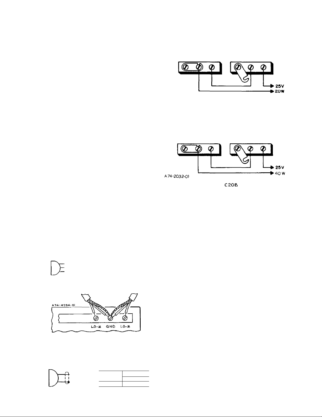
CONNECTING AMPLIFIERS IN SERIES
Pairs of Bogen ClOB or C20B amplifiers can be connected in
series to effectively double the power output into the same speaker
system. See figure 2 for eonnection diagram. Be certain to remove
the link between COM and GND of amplifier No. 2, Note that this
arrangement is for unbalanced speaker lines. For balanced lines
also remove the link between COM and GND of amplifier No. 1.
The input cabling must be arranged to parallel the inputs of the
two amplifiers, and the volume and tone controls of both
amplifiers must be at the same setting to assure that each amplifier
will share the load equally.
Page 3

OPERATION
ACCESSORIES
POWER: The front panel on-off switch applies power to the
amplifier. It has no effect upon equipment connected to the
auxiliary receptacle on the rear panel. The switch illuminates to
indicate that power is on.
MIC 1,2: The MIC2/ AUX selector switch should be in the MIC2
mode. The MIC controls are used to adjust the volume of the
microphone inputs. Rotate the control clockwise to increase
volume or counterclockwise to decrease volume. When micro
phone is not in use, be certain to turn control to minimum position.
AUX: Set the MIC 2/AUX selector switch to AUX. The AUX
control is used to adjust the volume of the auxiliary input. Rotate
the control clockwise to increase volume and counterclockwise to
decrease volume. Rotate the control to the minimum position
when auxiliary input is not used.
MICROPHONE PRECEDENCE: A built-in circuit provides
muting of the AUX channel. Connections are made from an
external switch to the AUX MUTE terminals. An SPST
normally-open switch is required for this function. When contacts
are closed, the AUX channel is muted.
TREBLE: Use the TREBLE control to adjust the tonal balance of
the amplifier output.
WMT-l LINE-MATCHING TRANSFORMER: The Bogen
WMT-1 Line-Matching Transformer provides an impedance
match between the amplifier and a 0 level, 500/ 600 ohm line. This
may be a telephone line connected to the switchboard for internal
paging or used with a wired music system. No soldering is required
to connect the WMT-1 to the amplifier.
To connect the input from a balanced 500/600 ohm telephone
line, mount the WMT-1 on the rear panel of the amplifier, using
the holes indicated on the rear panel. Connect the input line to the
three-screw terminal board on the WMT-1. Connect the phono
plug on the WMT-1 cable to the AUX jack on the rear of the
amplifier. If this jack is being used for other auxiliary equipment,
the WMT-1 may be connected to the MIC input. In order to do
this, the WMT-1 wiring must be modified as described in the
instruction sheet supplied with the WMT-1.
WMK-1 IN-WALL MOUNTING KIT: The Bogen Model
WMK-1 In-Walt Mounting Kit is designed to mount the amplifier
flush in a wall. Depth of the mounted unit is 3V4 inches.
MODEL RPK-35B RACK PANEL KIT: The RPK-35B rack
panel is designed to mount the ClOB or C20B amplifier in a
standard 19" sound rack.
Before fitting the panel to the amplifier, remove the rubber
feet from the bottom of the amplifier. Slide the amplifier into
the rack panel from the rear. Using the screws from the feet of
the unit, secure upward through holes in the panel and the
bottom of the amplifier, where the feet had been mounted.
Overall dimensions of the RPK-35B are 3-1/2" H x 19" W
with side panels 6-13/32" D (8.9 x 48.3 x 16.3 cm). Cutout
dimensions are 2-5/8" x 11-7/16" (6.6 x 29 cm). The panel is
fabricated from cold-rolled steel and has a black finish.
I UNLESS OTKERUdSE SPECIFIED ALL
RESISTORS ARE l/4WH0%
MIC Z/AUX f—
MUTE p
SWITCH /_
CUSTOMER T
О
SUPPLIED ^—
T Ю1
Ii*0D£l
СЮВ
&5-0WOOO
C209ез-ofi-ooo
POWER
nlflRrNT
_
Z CAPACITORS >£RE m MFD
i
VOLTAGES ARE +DC MEASURED TO GNO.
WITH A V.T.VM AND MAT VARV tZOfe
Figure 3 — Schematic Diagram, Models ClOB & C20B
 Loading...