

Page 1
OWNER’S GUIDE
MODEL A12
A-SERIES ENVIRONMENT-PROOF
HIGH-OUTPUT/LONG-THROW LOUDSPEAKER
Specifications subject to change without notice.
© 2014 Bogen Communications, Inc.
54-2172-01F 1503
Page 2
A12 Loudspeaker (1)
Mounting Knobs (2)
Yoke (1)
Rubber Friction Disk (2)
Safety Attachment Bolt (1)
Ownerʼs Guide (1)
PACKAGE CONTENTS
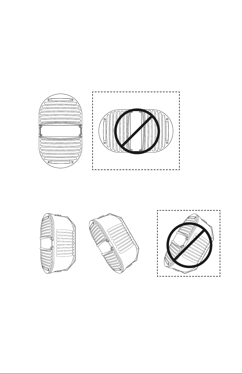
SPEAKER ORIENTATION
CORRECT
The A12 Armadillo Loudspeaker is acoustically designed to operate in a vertical
orientation. This orientation will provide 90 degrees of horizontal coverage and
45 degrees of vertical coverage.
WRONG
The A12 is a ported speaker, designed to shed water, and includes a unique waterrepellent scrim. This scrim covers the ports and horn throat to slow the ingress of
water, but a small amount of water may still enter the cabinet. Weep holes are provided at the bottom of the speaker baffle to drain any water that enters the cabinet.
NOTE: It is very important that the speaker be mounted with its face either vertical
or facing down. Never install the speaker with the face tilted up, as this will undermine the water-shedding aspects of the design and allow excessive water to enter
the cabinet.
WRONG
2
CORRECT
Page 3
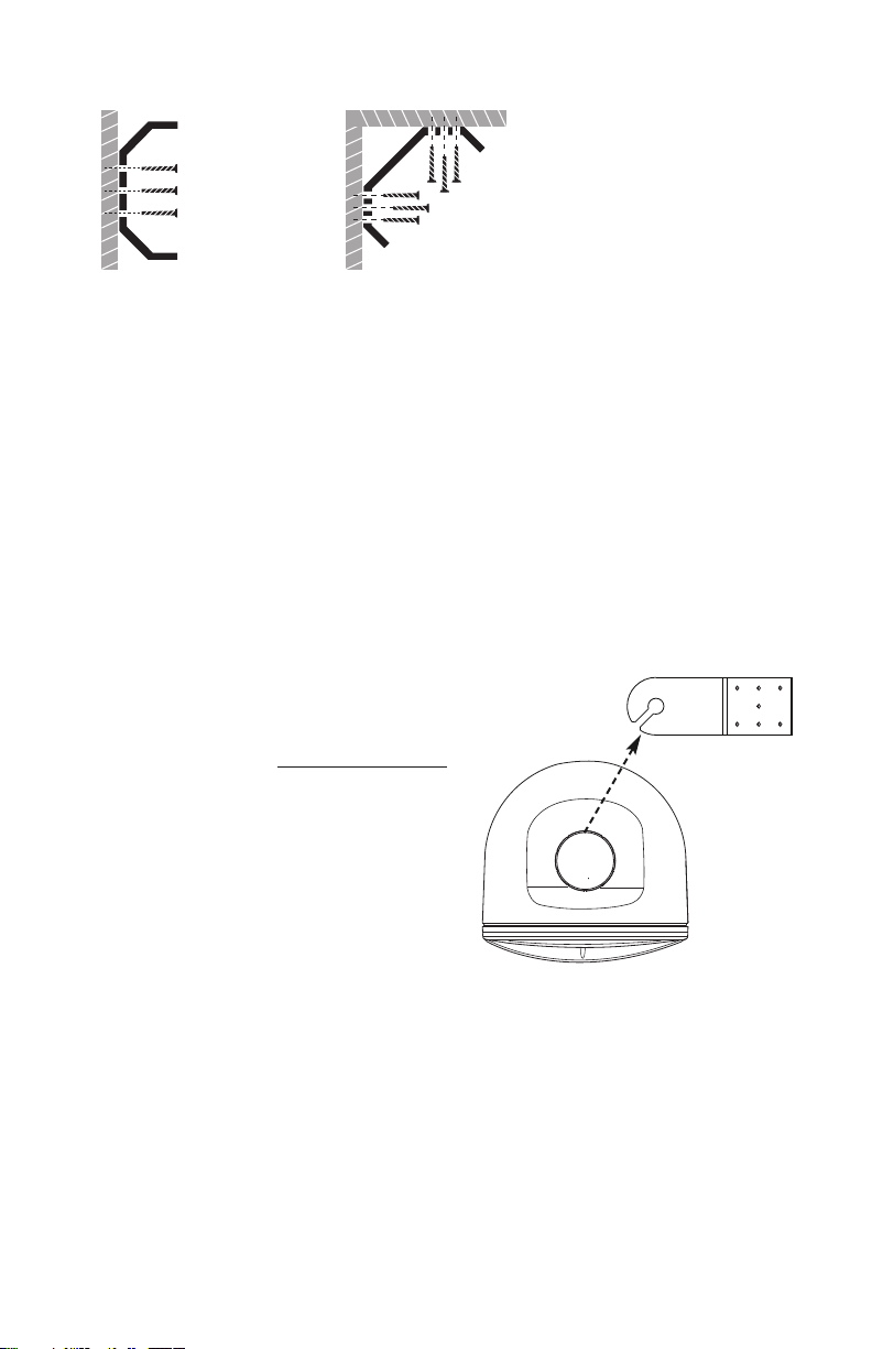
YOKE INSTALLATION
After selecting the speaker location, securely attach the yoke to the surface. An
Adjustable Tilt-Mount Adapter (TMA812) is available to provide various tilt angles.
The TMA812 allows attachment to walls and posts.
WARNING: Mounting brackets must be secured in accordance with local codes.
If in doubt, consult a professional contractor to determine the integrity of the structure to which the bracket will be attached. When required, a safety cable can be
secured to the back of the speaker using the threaded brass insert on the back of
the speaker housing and the forged steel safety bolt (included).
MOUNTING THE SPEAKER ON THE YOKE
The A12 yoke allows the speaker to be
slipped onto it with the locking knobs
attached. First, both knobs need to be
removed and the supplied rubber friction
disks applied to the speaker enclosure
where the knobs clamp. Do not apply the
friction disks directly to the mounting
knobs. Next, screw the knobs back onto
the enclosure about two turns and simply
slide the knob shafts down the slots in the
yoke. Now tighten the knobs making sure
that the shoulder of the knob seats
properly through the large hole at the end
of the yoke.
SOME FACTORS TO CONSIDER
Distance is not the only factor affecting sound intensity. Also consider what adjacent
surfaces may affect the sound (including but not limited to buildings, walls, and
overhangs). These structures may provide positive effects (low frequency
reinforcement) or negative effects (high-frequency reflections that will degrade
intelligibility).
TOP-DOWN VIEW
WALL MOUNT
90° WALL/CEILING MOUNT
(Secure both ends)
3
Page 4

Low-impedance:
Remove jumper, use
COM (–) and
16Ω terminals.
Jumper can be installed on
any two unused terminals
for safekeeping.
REAR-PANEL CONNECTIONS
70V:
With jumper in place, use
COM (–) and one tap
selection (choose 8, 16,
32, 64, or 128 watts).
Shown without jumper
UNDERPOWERING VS. OVERPOWERING
Surprisingly, speaker damage can be caused by amplifiers with too little power.
An underpowered, overdriven amp sends heavily distorted, clipped audio to the
speakers. This can damage the high-frequency drivers. Clipping is usually audible;
it may vary from a harsh sound to a fuzzy or blurry sound. If you hear clipping at
loud volume levels, turn down the volume until the distortion is no longer present.
On the other hand, overpowering a speaker can cause mechanical damage or electrical failure by overstressing the speakerʼs components. The speaker must be
powered appropriately to ensure its longevity and performance.
PAINTING
The speaker enclosure and grille can be painted with automotive paints or spray
paints specially designed to adhere to plastics. Perforated grilles require special
care when painting so that the holes do not become plugged with paint. Applying
several very light coats works best. Be sure to mask the port and horn throat scrim
so that no paint will get on those items.
4
Page 5

70V SYSTEM CONFIGURATION
Note: Jumper in place
To next speaker
This example uses the 16W tap.
In a real installation, any of the
five 70V taps (8W, 16W, 32W,
64W, or 128W) may be used.
From amp
When designing a 70V system, the total of all the power tap settings of all the
connected speakers cannot exceed the output power of the 70V amplifier. The
example below shows five speakers connected in parallel. Using the 16W terminals,
an amplifier is needed with a power rating of at least (5) ×(16) = 80W. A good rule
of thumb is to select an amplifier with 20% more power; in this case, an amplifier
that delivers about 100W.
When using multiple low-impedance speakers wired in parallel, it is important to
know the total load that these speakers present to the amplifier and to
select an amplifier that is stable into that load. The A12 has a 16-ohm input
impedance which allows for easy paralleling of multiple speakers. In the example
on the next page, four speakers are paralleled on each amplifier output, so that
each run has a total impedance of 4 ohms. The amplifier is selected to be stable
into this load impedance.
LOW-IMPEDANCE SYSTEM CONFIGURATION
5
+
+
Page 6

Example of Low-Impedance System Configuration
+
_
+
_
To next speaker
From amp
Jumper has been removed
Note: Jumper stored for safekeeping
Total load impedance can be calculated this way:
Rs is the impedance of the speaker, for the A12 it is equal to 16 ohms.
Note: If all speakers are the same Rs , it is simply:
Low-impedance amplifiers have power ratings based on driving a particular load
impedance, typically a 4-ohm load. Some rate power into an 8-ohm load. If the
speaker loadʼs impedance is greater than the amplifierʼs rated impedance, the
speaker will not consume the amplifierʼs total rated power. Since the A12 is a
16-ohm speaker, operating a single A12 with an amplifier rated for 4 ohms will
result in the A12 speaker consuming only 1/4 of the amplifierʼs maximum capacity.
Likewise a single A12 will consume only 1/2 of the power capacity of an amplifierʼs
8-ohm power rating. Most real world applications will require more than a single
A12, and paralleling the speakers will decrease the total impedance of the load as
mentioned above.
6
AMPLIFIER WITH DUAL 4 OUTPUTS
16 16 16
16 16 16
4 SPEAKERS PER CHANNEL CONNECTED IN PARALLEL
16
1
(1/Rs + 1/Rs ... 1/Rs)
= Total Load Impedance
Rs
# of Speakers
= Total Load Impedance
16
Page 7

LIMITED WARRANTY; EXCLUSION OF CERTAIN DAMAGES
The Bogen Model A12 is warranted to be free from defects in material and workmanship for five (5) years from
the date of sale to the original purchaser. Any part of the product covered by this warranty that, with normal
installation and use, becomes defective (as confirmed by Bogen upon inspection) during the applicable warranty
period, will be repaired or replaced by
Bogen, at Bogen’s option, provided the product is shipped insured and prepaid to: Bogen Factory Service
Department, 4570 Shelby Air Drive, Suite 11, Memphis TN 38118, USA. Repaired or replacement product will
be returned to you freight prepaid. This warranty does not extend to any of our products that have been
subjected to abuse, misuse, improper storage, neglect, accident, improper installation or have been modified
or repaired or altered in any manner whatsoever, or where the serial number or date code has been removed
or defaced.
THE FOREGOING LIMITED WARRANTY IS BOGEN’S SOLE AND EXCLUSIVE WARRANTY AND THE
PURCHASER’S SOLE AND EXCLUSIVE REMEDY. BOGEN MAKES NO OTHER WARRANTIES OF ANY
KIND, EITHER EXPRESS OR IMPLIED, AND ALL IMPLIED WARRANTIES OF MERCHANTABILITY OR
FITNESS FOR A PARTICULAR PURPOSE ARE HEREBY DISCLAIMED AND EXCLUDED TO THE MAXIMUM EXTENT ALLOWABLE BY LAW. Bogen's liability arising out of the manufacture, sale or supplying of
products or their use or disposition, whether based upon warranty, contract, tort or otherwise, shall be limited
to the price of the product. IN NO EVENT SHALL BOGEN BE LIABLE FOR SPECIAL, INCIDENTAL OR
CONSEQUENTIAL DAMAGES (INCLUDING, BUT NOT LIMITED TO, LOSS OF PROFITS, LOSS OF DATA
OR LOSS OF USE DAMAGES) ARISING OUT OF THE MANUFACTURE, SALE OR SUPPLYING OF PRODUCTS, EVEN IF BOGEN HAS BEEN ADVISED OF THE POSSIBILITY OF SUCH DAMAGES OR LOSSES.
Some States do not allow the exclusion or limitation of incidental or consequential damages, so the above limitation or exclusion may not apply to you. This warranty gives you specific legal rights, and you may also have
other rights which vary from State to State.
Products that are out of warranty will also be repaired by the Bogen Factory Service Department – same
address as above or call 201-934-8500. The parts and labor involved in these repairs are warranted for 90
days when repaired by the Bogen Factory Service Department. All shipping charges in addition to parts and
labor charges will be at the owner's expense. All returns require a Return Authorization number. For most
efficient warranty or repair service, please include a description of the failure.
11/2014
SPECIFICATIONS
A12
Frequency Response (-10 dB)
*
55 Hz to 17.5 kHz
LF Driver
Dual Metal-Composite 6-1/2" Cone Woofers,
MLS Voice Coil Guidance System
HF Driver
Weatherproof 1.9"Mylar Diaphragm
Constant Directivity Horn, 1" Exit
Sensitivity (1W/1 m)
94.5 dBspl
Dispersion 90° Horizontal, 45° Vertical
Impedance Ratings
Low (16 ohms) / High (70V)
Power Input (Max.)
225W @ 16 ohms; 128W @ 70V
Power Settings (in watts)
70V: 128, 64, 32, 16, 8
Grille Material Perforated Polypropylene
Enclosure Material Mineral-filled Polypropylene, with UV Inhibitor
Terminations
Dual 4-Terminal Barrier Strips with Gold-plated,
Rust-proof Screws
Product Weight 22 lb.
Speaker Dimensions
10-1/4"W x17-7/8" H x 11-3/4" D
Included Accessories Color-matched, Stainless Steel Mounting Bracket
Optional Accessories
Adjustable Tilt-Mount Adapter
(Model TMA812, sold separately)
Environmental
Designed to meet or exceed Mil-Std-810E
* Half-space response
7
Page 8

www.bogen.com
 Loading...