

Page 1

© 2003 Bogen Communications, Inc.
All rights reserved.
Specifications subject to change without notice.
54-2101-01A 0308 Printed in Taiwan.
Pendant Speaker
Model: 700286198 / 700286206
(Black) (White)
Installation and Use Manual
Issue 1, August 2003
Page 2

Product Description
You have purchased one of the finest pendant loudspeakers available today. Please
familiarize yourself with this product by reading and reviewing the following descriptions and diagrams.
These loudspeakers include a "spiderless" woofer that utilizes a high-gauss ferrofluid to guide the voice coil through the magnetic field.The benefits over conventional
woofers with cloth spiders are several, including the ability to constantly adjust voice
coil alignment, extend linear excursion, and the most efficient path for cooling the
voice coil.
In addition, the use of metal-alloy cone structures provides several benefits over the
usual paper or plastic cone, such as elimination of cone flex or "break-up" in the
operating ranges, additional thermal path for the voice coil to stay cool, and an
extremely stable cone structure unaffected by the environment.
The pendant loudspeaker is a full-range, wide dispersion system providing overhead
sound coverage where ceiling structures are high but the sound needs to be closer
to the audience/listener. Cable kits are provided for use as safety and main drop
cables.
Settings for 70V and 100V high-impedance systems, as well as a low-impedance
(16-ohm) position, are provided.
All models feature a removable snap-lock input connector, providing easy wire connection for input as well as loop-through to the next speaker.
Page 3
Product Diagrams
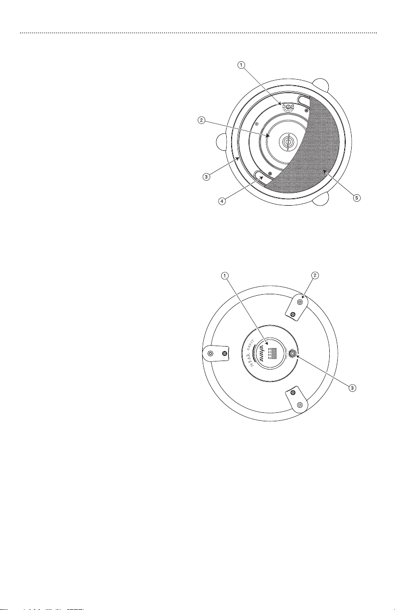
Front Drawing
1.Tap Selection Switch
2. Coaxial Driver Assembly
3. Grille Retention Slot
4. Bass Tuning Vent (x2)
5. Perforated Steel Grille
Rear Drawing
1. Snap-Lock Input Connector
2. Suspension Points (x3)
3. Safety Cable Suspension Point
Package Contents
(1) Pendant Speaker
(1) Installation and Use Manual
(1) Snap-Lock Input Connector
(1) Quick-Snap Clip
(2) Cable Kits
(3) Suspension Cables with Forged Eye Bolts
(3) Nuts (maybe installed onto eyebolts)
Front Drawing
(grille partially shown)
Rear Drawing
1
Page 4

Speaker Installation
If the power level is known, then select it using the front-mounted selector switch
prior to installing the speaker. See section Selecting Power Levels.
Speaker Grille Removal
Insert a pocket knife blade between the grille and the
bezel about a
1
/4" deep and then gently pry the grille
upwards. Do this in multiple places around the circumference of the grille to free the grille.
Speaker Grille Installation
The speaker grilles fit tightly! Make sure the tap settings are correct prior to installing grille. Push the
speaker grille in until it can go no further. Then, slap
around the edge of the grille to seat the grille. The
grille is properly seated when it is flush with the edge
of the bezel.
Suspension Cable Assembly
1. Screw nuts onto the eye bolts all the way to
the flange.
2. Screw in eye bolts with captured cable sec-
tions in to the three suspension points.
Do not overtighten.
3. Snap loops of free end of cable sections into
quick-snap clip.
4. Connect quick-snap clip to drop cable. The
supplied cable kit is suitable for use as the
drop cable.
Safety Cable
The speaker includes a safety cable suspension
point for extra protection.The included cable kit
must be used as a safety cable. Refer to instructions with cable kits for proper use.
2
IMPORTANT
The anchor point and any hardware used
to anchor the speaker must be able to
support the speaker’s weight under all
conditions. IF YOU ARE NOT SURE OF
THE PROPER CAPACITY OF THESE
ITEMS TO USE, CONSULT A STRUCTURAL ENGINEER. Mount only one speaker
per supplied quick-snap clip.
1.
2.
3.
4.
Page 5

Speaker Wiring
Wiring is terminated at a snap-lock input connector. There are two positive and two negative terminals to accommodate daisy chaining
of speakers in a system. All wiring should be
done prior to installation and then plugged
into the rear of the speaker.
Daisy Chaining
The speaker’s snap-lock input connector
allows for easy daisy chaining of speakers by
providing a second terminal of each polarity.
Refer to the figures for proper wiring for daisy
chaining of terminals.
Speaker Phasing
Keep the same polarity terminals wired together to ensure correct phasing. In order
to provide the best possible sound, all of the speakers in a system need to be
pushing out and pulling in at the same time.
If the connections to one speaker in a system are reversed from the others, that
speaker’s movement will be out of sync with the other speakers.This will result in a
loss of low frequency response and will effect the overall performance of the
system.
3
Page 6

Selecting Power Levels
The front-mounted selector switch is used to
set the appropriate power level or impedance
for your system. Using a small flat-blade screwdriver, turn the knob until the slot points to the
power level you require.
70V/100V Systems
Both power setting scales for 70V and 100V systems are labeled on the speakers. On the 100V
scale, the last position clockwise is marked with
a (not available) symbol.Do not use this position in 100V systems.
16
ΩΩ
Systems
The fully counterclockwise position of the setting switch is the 16-ohm position.This
setting is suitable for use with low-impedance amplifiers that typically support 4- or
8-ohm speakers.The speaker’s higher, 16-ohm impedance makes it easier to combine
multiple speakers into series - parallel networks while keeping the total system
impedance at a level suitable for low-impedance amplifiers.
4
Page 7

Specifications
5
SPECIFICATIONS
700286198 & 700286206
Frequency Response (-10 dB)
*
60 Hz to 19 kHz
LF Driver 6-1/
2" MDT Metal-Alloy Cone
HF Driver 20 mm (3/4") Polycarbonate Dome
Sensitivity (1W/1M) 89.5 dBspl (Average 100 Hz - 10 kHz)
Impedance Ratings
Low (16 ohms) / High (70V/100V)
Power Input (Max.)
100W @ 16 ohms; 32W @ 70V/100V
Power Settings (in watts)
†
70V: 32, 16, 8, 4, 2, 1
100V: 32, 16, 8, 4, 2
Enclosure Material ABS
Grille Material Powder-Coated Perforated Metal
Terminations 4 Terminal Snap-Lock Input Connector
Product Weight
10 lb.
Speaker Dimensions
15" dia. x 9-1/4" D
Included Accessories
(1) Snap-Lock Input Connector; (1) Quick-Snap Clip
(2) Cable Kits; (3) Nuts; and
(3) Suspension Cables with Forged Eye Bolts
Enclosure Finish & Color Textured White or Black
*
Free Space Response, 16-ohm input.
† Front panel, switch-selected.
Page 8

©2003 Bogen Communications, Inc.
Specifications are subject to change without notice.
www.paging-solutions.com
1-877-852-PAGE
 Loading...