

Page 1
BOGEN
A DIVISION OF LEAR SIEGLER, INC.
MCT-1
MODELS
15-1,
SERIES 15
15T-1,15-2,15-3
DESCRIPTION
The
Bogen
Series 15-1 Centralized School Sound
System is designed to serve up to 50 rooms. It incorporates one Model MCT-1 Control Center and either one
or two Model SBS-25 Switchbanks, and is housed in a
desk-top consolette. The Series
15T-
1 accommodates up
to 25 rooms and includes one Control Center, one
Switchbank and one Model TP-160B AM/FM Tuner
housed in a desk-top consolette. The Series 15-2 consists
of one Control Center, one or two Switchbanks, one
AM/FM Tuner and one BSR 3-speed record changer. It
is housed in a desk-top, dual consolette and serves up to
50 rooms. The Series 15-3 consists of one Control
Center, one or two Switchbanks, one AM/FM Tuner
and one 3-speed record changer. It can accommodate up
to 50 rooms and is operated from a sturdy free-standing
console.
Each system has one 35-watt program channel and an
independent 4-watt intercom channel. The program
channel has two low-impedance microphone inputs
which can be used balanced or unbalanced. It also has
inputs for radio, phono and tape program sources and a
fader control to select either radio or phono-tape. The
selected program may be used alone or may be mixed
with the microphone program.
The MCT-1 control panel has a loudspeaker which
serves as both a program monitor speaker and an intercom transmitter/receiver. By means of the intercom
channel, the operator may hold a two-way conversation
with occupants of any room without disturbing the program being transmitted to other rooms. If desired, the
intercom channel also may be used to permit the operator to monitor any selected room through its room
speaker.
Model 15-2
In addition to the control panel, each Series 15
consolette or console has one or two switchbanks containing the individual room selector switches. In the standard system, these are 3-position lever switches used to
connect each room speaker to either the program (A)
channel or the intercom (C) channel, or to disconnect
the speaker from the system (Systems with optional
light-annunciator call circuit have four-position lever
switches). The units have an Emergency mode of operation which overrides these selector switches. When
operating in Emergency, the operator can transmit from
the control panel speaker to all room speakers, regardless of the settings of the room selector switches or of
other program inputs to the speakers. The Emergency
function operates whether the power switch is on or off.
INSTALLATION
UNPACKING
Inspect the shipping container and unit for indications of improper handling. The unit was carefully
checked before leaving the factory. If the unit has been
damaged, make an
immediate
claim to the dealer or distributor from whom it was purchased. If the unit was
shipped to you, notify the transport company without
delay and place your claim.
Printed in USA
8005
CENTRALIZED SCHOOL SOUND SYSTEM
54-5665-04
Page 2
LOCATION OF
CONSOLE/CONSOLETTE
Where possible locate the console centrally, relative
to the rooms being served, in order to minimize the
length of speaker cables. The rear of the unit must
remain accessible for maintenance and for changing input and output connections. It is advisable that the unit
be oriented in such a manner that the operator, program
director and other interested parties are able to observe
the controls at all times. Provide adequate lighting and
ventilation. Do not locate the unit close to heat sources,
such as radiators and warm-air ducts, or against a wall
which prevents proper ventilation.
The Series 15-1 and
15T-1
consolettes are 21¼” (54
cm.) wide x 16” (40.6 cm.) high x 16” deep. The Series
15-2 consolette is 40½” (102.9 cm.) wide x 16” high x
16” deep. The Series 15-3 console is 22” (55.9 cm.) wide
x 46” (116.8 cm.) high x 31” (78.7 cm.) deep.
POWER
Connect the 3-wire cord with ground to a
105-125V,
50/60
Hz source. Make certain that the ground terminal
of the power receptacle connects to earth ground.
Two 50W AC power receptacles are provided on the
rear panel for a tuner, automatic record changer or auxiliary equipment. Line voltage is applied to these components when the consolette or console power switch is
on. Plug AC line cords into appropriate receptacle.
INPUT CONNECTIONS
MICROPHONE INPUTS. Two terminal strips on
the rear of the MCT-1 provide for two low impedance
balanced or unbalanced microphone inputs.
Twoconductor shielded microphone cable should be used
(Bogen #l008
or equivalent). Connect shield to terminal
1.
TUNER/PHONO-TAPE INPUTS. Two jacks accept
single-conductor shielded cable.
TAPE RECORDER/BOOSTER AMP INPUT. Ac-
cepts a two-conductor shielded cable
(Bogen
BB 8450 or
equivalent).
INTERCOM CALL-IN LINE. Connect parallel lines
from station call-in switches with 2-conductor shielded
cable. Connect shield to terminal 3.
SWITCHBANK
CONNECTION. Eleven-pin plug
connects three shielded pairs plus annunciator wire
from a switchbank. Also accommodates three lines for
optional telephone system.
TIME CLOCK INPUT. Terminal strip connects a
single-circuit time clock, closing contacts to activate the
optional Model SST-l Module.
GENERAL WIRING
RUNNING CABLES
WIRES. Class II wiring may be used for all audio and
annunciator lines. Make certain to properly support
cables to prevent sagging or strain. Keep wires clear of
objects which would subject them to heat, friction, or
other abuse.
Use No. 20 AWG shielded pairs with insulated outer
jacket (Bogen BB-8450, or equivalent) for speaker lines.
Annunciator lines require a third wire, which usually is
No. 22 AWG insulated wire with red insulation (Belden
8937, or equivalent). The number and types of wires
running from each room to the consolette and running
inside the classroom depend upon the type of speaker
operation required. Consult Table I for the wires required in your particular system.
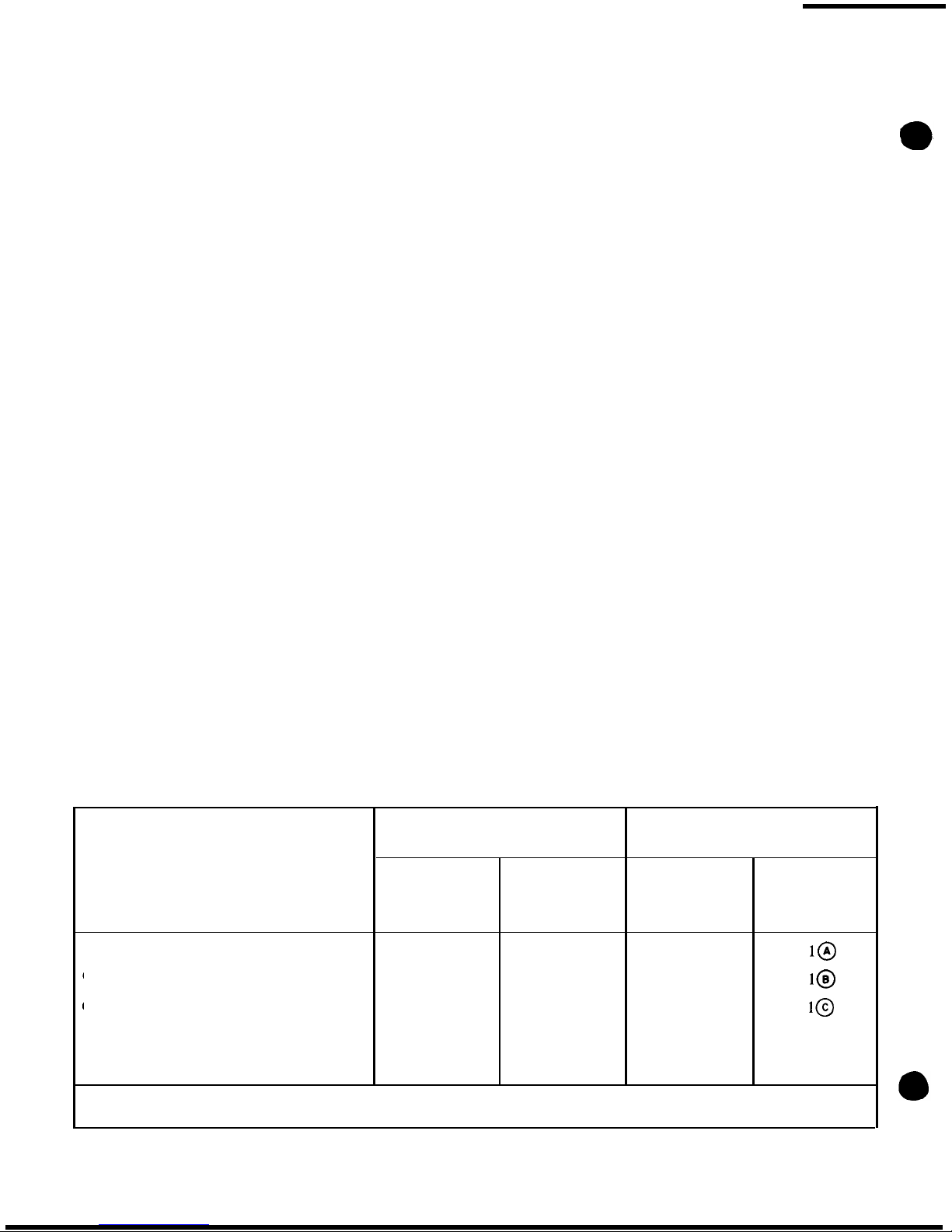
TABLE I. CABLE RUNNING CHART FOR SERIES 15
Wires from Room to Consolette
Wires From Room Switch
to Room Speaker
Type of Classroom Switch or Device
Shielded Pair
No. 22 AWG
Used with Speaker
Shielded Pair
(Jacketed)
Single
Conductor
(Jacketed)
Refer to
(Bogen
BB-8450)
Figure
(Belden
8937)
(Bogen BB-8450)
None (Speaker Only)
1
0
0
Call (Model
CA-l0)
1
1 1
Call/Privacy (Model CA-l 1)
1
1 1
Voice Call-In, Non-Private
2* 0
1
2, 7
(Model CA13)
*Alternate method:
Run
two cables from room nearest consolette and one cable from each remaining room. Run
one cable in a loop or branch circuit connecting all room switches.
-2-
Page 3
OUTLET BOXES. Where flush-mounting switches
are used, single-gang outlet boxes will be installed. In
installing such boxes, make certain to place them in a
location that permits personnel to operate the switch
while communicating via the room speaker. The normal
height (above the finished floor) for room switches is
approximately four feet, while speakers are normally
placed at a height of about seven and one-half feet.
SOLDERING INSTRUCTIONS
SOLDER.
Do not use acid-core solder or acid paste.
Make all solder connections with standard
60/40 resincore radio solder. Do not apply excessive heat. Soldering irons or guns from 75 to 200 watts will provide
ample capacity.
GROUNDS.
Do not connect cable shields to earth
ground or to convenient metal objects.
It
is important to
connect cable shields only as shown in the wiring
diagrams.
CLASSROOM WIRING
CONNECTIONS
Refer to the left-hand column of Table I for the type
of classroom operation used in your system. The corresponding right-hand column calls out the wiring diagram
required. Solder the wires as shown in the proper diagram and wrap with insulating tape.
CAUTION
Make certain to connect
all
wires in accordance with the color codes given on the diagram.
SECURING SWITCHES
The Model CA switches are designed for flush
mounting in a standard single-gang electrical outlet box,
BOGEN
25-VOLT
ROOM
LINE MATCHING
SPEAKER TRANSFORMER
(SEE NOTE-P)
(SEE NOTE-I)
--
I
--
22AWG MIN.(TYP.)
(BELDEN 8937, OR
EOUIV.)
TO CONSOLE ‘SWITCH BANK
BOGEN 25-VOLT
ROOM
LINE MATCHING
SPEAKER TRANSFORMER
(SEE
NOTE-2)
TO CONSOLE
SWITCH BANK
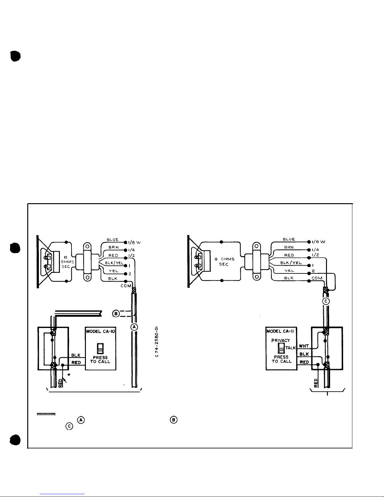
NOTES :
I- CONNECT AS FOR NON-PRIVATE OPERATION, AS FOR NON-PRIVATE WITH ANNUNCIATOR,
OR AS
FOR PRIVATE WITH ANNUNCIATOR.
2-
MODEL
TS-2A (1/2
WATT TAP) SHOWN.
SEE TEXT FOR
TS-I6A
TRANSFORMER
AND ADDITIONAL INFORMATION.
Figure 1 - Connection Diagram,
Speaker
Installation
-3-
Page 4
74-2588-A
LINE
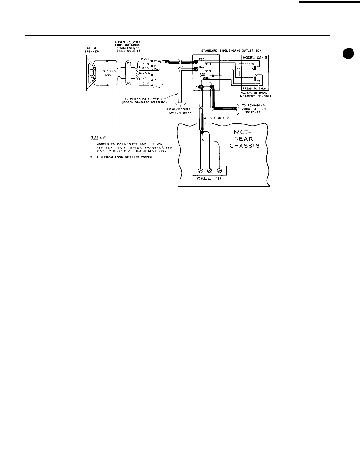
Figure 2 - Room Speakers with Voice Call-In Switch, Connection Diagram
or for surface mounting in a standard deep single-gang
wire mold outlet box. Install the box in a location which
provides convenient access to both the switch and the
room speaker.
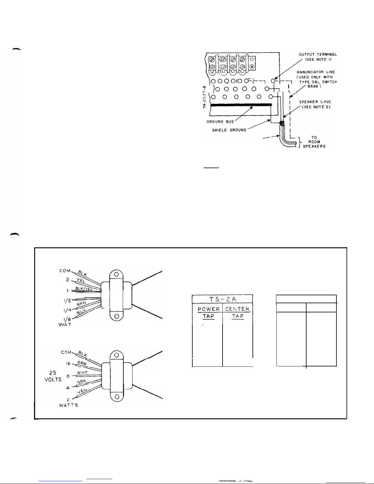
LINEMATCHING TRANSFORMERS
The installation diagrams show
Bogen
line-matching
transformers of
¼
or %-watt capacity (Models TS-025
or TS-05). Other recommended transformers are shown
in figure 3. The console output is designed for a
25-volt
constant voltage distribution system and all system
loudspeakers must be provided with line-matching
transformers.
CAUTION
Speakers and transformers must be properly matched with respect to power
require-
men ts.
CONSOLETTE WIRING
Remove the Phillips-head screws securing the
louvered pane1 on the rear of the consolette (or console).
There are three rows of solder terminals across the rear
of each switchbank. Each selector switch corresponds
to the three terminals directly behind it, one terminal
from each row.
White tabs are provided for identifying the room controlled by each selector switch. Insert the tabs in the
slots provided in the transparent switch knobs. When
rooms are identified by number, it is common practice
to start numbering the switches from left to right (viewing from the front or operator position), starting with
the top switchbank.
SWITCHBANK WIRING
Wire the switchbanks as shown in figure 4. If annunciator lamps are used (Model SBL), always solder the
single annunciator wire to the top solder terminal. For
all switch banks, solder the speaker lines to the center
and bottom terminals, with the shield to the ground bus
bar.
This is the only place where speaker shields should
be grounded.
VOICE CALL-IN OPTION
Figure 2 shows the room connections and switch required for installing an optional voice call-in system.
The wiring must be completed by connecting the
shielded pair from the switch to the terminal strip on the
rear of the MCT-1 chassis. The polarity of the inner
conductors is not critical, but make certain to connect
the cable shield to the shield of the cable already con-
nected to the terminal strip.
Note that only one cable goes to the terminal strip.
Usually, the cables from all room switches are con-
nected by a common control cable and one cable is run
to the consolette. If this type of installation is not practical, then the control cables for two or more switches
are run to the consolette. In this case, connect all the
cables in parallel in a junction box at the consolette and
run a single control cable from the junction box to the
terminal strip on the MCT-1 chassis.
CALL/PRIVACY OPTION
Figure lc shows the room connections and switch
re-
quired for installing an optional annunciator/privacy
function in the intercom system.
4-
Page 5
CONTROL FUNCTIONS
All operating controls for the Series 15 Centralized
School Sound Systems are located on the front of the
consolettes (consoles). The Series
15T-1
is equipped
with an AM/FM radio tuner, while the Series 15-2 and
15-3 have both a tuner and an automatic record changer. The operating controls for the tuner and record
changer are described in their individual instruction
manuals.
MCT-1 CONTROL PANEL
The controls on the Model MCT-1 Control Panel are:
POWER ON-OFF SWITCH. Turns the system on and
off.
FUNCTION SELECTOR SWITCHES. These switches
determine the mode of system operation. These operating modes are:
1.
Microphone. Connects microphone input to program
channel (selected by MIC level control).
2.
Program. Permits transmission of program material
as determined by program distribution and program
output switches.
3.
Intercom. Enables and disables TALK/LISTEN
switch.
4. Emergency. Permits operator to transmit to all stations via panel speaker, regardless of switchbank settings. Overrides all program and intercom functions.
Operates with power switch On or Off.
5.
Talk/Listen. Allows operator to communicate with
room(s) selected on switchbank without affecting program distribution to remaining rooms. Enabled by Intercom switch; depress to talk, release to listen.
CONSOLE SWITCH BANK
TYPE SBL SWITCH
SHIELDED PAIR
(BOGEN
BB-8450, OR EOUIV.)
NOTES
I-TERMINALS CORRESPOND TO SWITCH ON OPPOSITE
SIDE OF FRONT PANEL.
2-DRESS SPEAKER LEADS TO PREVENT SHORTING
LOWER TERMINALS TO GROUND BUS.
Figure 4 - Consolette Switch Bank, Connection
Diagram
LEVEL CONTROL SWITCHES
1.
Microphone. Fader control sets level of Mic 1 or Mic
2 program as indicated on output meter. May be used
with Program level control for mixing.
25
VOLTS
TS-2A
8
RED
SEC
TS
TS -
16A
OHMS
ONDARY
8
OHMS
SECONDARY
l/8 W
RED
l/4
w
BLK/YEL
l/2
w
YEL
I w
YEL
2
W
-
TS-
16A
POWER
TAP
2
w
4
w
8 w
16
W
CENTER
TAP
WHT
ORN
ORN
Figure 3 -Bogen Line-Matching Transformers
-5-
Page 6

2. Program. Fader control sets level of radio or
phono/
tape program as indicated on output meter. May be
used with Microphone level control for program
mixing.
3. Intercom. Sets outgoing level of intercom transmission to room speakers.
4.
Monitor. Sets panel speaker level in program and
intercom modes.
5.
Tone. Provides flat response or reduces high-fre-
quency response as control is moved toward HI CUT.
PROGRAM OUTPUT METER. Color-coded to clearly
display 25 V reference level.
PROGRAM SWITCHES
1.
Program Distribution. Functions when program
output selector is in SEND.
NORM(a1)
position provides switchbank control over program distribution.
ALL position distributes program to all rooms not con-
nected to the intercom.
2.
Program Output. SEND position enables program
distribution switch. SET position disconnects program
output from load for monitoring or presetting prior to
distribution. Does not offset intercom functions. The
program output switch should not be left in the SET
position. Once adjustment is made, switch should be
returned to SEND position.
SWITCH BANKS
MODEL SBS SWITCHBANK. Standard consolettes
are equipped with one or two Model SBS Switchbanks.
Each switchbank has 25 three-position lever switches
for connecting individual rooms to the system. Each
switch functions as follows:
A - (Up position)
-
Connects classroom speaker to
program channel for distribution of microphone, radio,
or phono program.
0
-
(Center position)
-
Disconnects classroom speaker
from system, except when consolette is operating in
Emergency mode.
C
-
(Down position)
-
Connects classroom speaker to
intercom channel.
MODEL SBL SWITCHBANKS (OPTIONAL). If
the system is equipped with an optional light-annunciator call system, the consolette switchbanks will have
four-position lever switches. These switches operate
exactly as those in the Model SBS Switchbank, except
that there is a “B” (top) position of the switches which
is not used. If a switch is placed in the “B” position, it
functions exactly the same as in the “A” position.
OPERATION
NOTE
Before attempting to operate for the first
time after installation, check all input and
output connections and make certain the
consolette is connected to a power outlet.
TO TURN
CONSOLETTE-ON
Set POWER ON-OFF switch to ON position.
TO DISTRIBUTE MICROPHONE
PROGRAM
Move program output switch to SET position. Depress MIC function switch. Select microphone level with
MIC fader control knob according to
contro1
panel
speaker volume and/or reading on PROGRAM LEVEL
output meter. When appropriate level is reached, distribute program by moving program output switch to
SEND position. Select either NORM for Switchbank
control over distribution or ALL for distribution to all
stations not connected to the intercom. (May be used in
conjunction with PROGRAM level control for program
mixing).
TO DISTRIBUTE RADIO/PHONO-TAPE
PROGRAM
Move program output switch to SET position. Depress PROG function switch. Select level of radio/
phono/tape
program with PROGRAM fader control
knob according to control panel speaker volume and/or
output meter reading. Distribute program by switching
program output to SEND position.
To distribute output from a tape recorder, connect
the 2-conductor phone plug from the tape recorder to
TAPE IN jack on the control panel and follow procedure outlined above. Phonograph input will be automatically disconnected.
TO OPERATE ALL-CALL FUNCTION
Move program output switch to SEND position.
Move program distribution switch to ALL position.
Program is transmitted to all stations regardless of position of station selector switches. (Note: Disconnect intercom function; stations connected to the intercom will
not be affected).
TO COMMUNICATE WITH SELECTED
STATIONS
TO SEND. Depress INTERCOM function switch.
Select station to be contacted on switchbank panel.
Depress TALK/LIST switch to send; release switch to
monitor. Intercom level control should always be left at
the setting for normal transmission to room speakers.
(Note: does not affect program distribution to other
stations).
TO RECEIVE. If a voice call-in system is installed,
the station operator makes contact over the intercom
channel via the station speaker and CA-13 call switch,
and identifies his or her station. To respond to call,
select station on switchbank and depress TALK/LIST
-6-
Page 7

switch. Speak clearly into the control panel speaker
from a distance of approximately 12” (Note: Intercom
function switch must be depressed to receive VOICE
CALL IN from stations).
TO OPERATE EMERGENCY
Depress
EMERG
switch and speak clearly into panel
speaker. Message is transmitted to all stations regardless
of switchbank settings, program and intercom function
settings, and position of POWER ON-OFF switch.
ACCESSORY EQUIPMENT
LIGHT-ANNUNCIATOR CALL SYSTEM
If a light-annunciator call-in function is installed, the
optional Model SBL Switchbank panels have an annunciator lamp above each station selector switch. Each station has a call switch to light the appropriate lamp.
When lamp lights, move the corresponding switch to
“C”
position. The intercom channel is now open for
normal intercom communication. The control panel
also has a built-in tone alert to provide audible annunciation that supplements switchbank lamps.
PRIVACY FUNCTION
Prevents the console operator from monitoring the
speaker station if the station is provided with the optional CA-l 1 CALL/PRIVACY Switch. A station in
the Privacy mode will still receive messages from the
consolette.
TIME TONE OPTION
The external single-circuit time clock closes contacts
that are normally open to activate the optional Time
Tone Module SST-l for timed, preset signals to station
speakers. Connects to terminal strip on the rear of the
control panel.
EXTERNAL BOOSTER AMPLIFIER
Model MT-60A or MT-
125B
(60 or 125 watts) provide
increased power output. To install, remove the MCT-1
top cover and cut the jumpers on the terminal strip
between points A, B and C, D as shown in figure 5.
Insert two-conductor shielded cable in hole F. Connect
25 V balanced output leads to terminal strip points B
and C. Connect the shield to E. Attach the cable from
the Tape Out/Booster output jack on the rear of the
MCT-1
to the Hi-Z input of the MT-60A or MT-125B.
Figure 5 -Connecting Booster-Amplifier
MAINTENANCE
CAUTION
There are no user-replaceable parts within
the unit. Have all in
ternal
servicing done by
qualified service personnel.
BOGEN SERVICE
We are interested in your
Bogen
equipment for as
long as you have it. If trouble ever develops, do not
hesitate to ask our advice or assistance. Information can
be obtained by writing to Service Department,
Bogen
Division, P.O. Box 500, Paramus, N.J. 07652.
When communicating with us, give the model and
series designation of your unit. Describe the difficulty
and include details on the electrical connections to associated equipment, and list such equipment. When we receive this information, we will send you service information if the trouble appears to be simple. If the trouble
requires servicing, we shall send you the name and address of the nearest
Bogen
authorized service agency to
which you can send your unit for repairs.
When shipping your unit, pack the amplifier well,
using the original shipping carton or a similar container
and filler material to prevent damage in transit. Send
the unit, fully insured and prepaid, via any responsible
carrier. The unit will be promptly repaired and returned
to you express collect.
-7
Page 8

TECHNICAL SPECIFICATIONS
Rated Output: Program: 35 Watts
Intercom:
4 watts
Frequency
Program:
100
to 20,000 Hz 2
dB
Response: Intercom:
Shaped for best voice
articulation.
Distortion:
Less than 3% @
35
Watts:
100
to
10.000 Hz
Noise Level:
Microphone:
-50
dB
Radio/Phone:
-60
dB
Sensitivity
:
Microphone: 300
µV
Radio/Phone:
100 mV
Tape In:
100 mV
Intercom:
4
mV
Inputs:
2 Microphones (Lo-Z, balanced or
unbalanced)
Radio
Phono
Tape In (Front Panel)
outputs:
Program: 25 Volts balanced
Intercom: 25 Volts balanced
Tape Out/Booster: 2 Volts
Switches:
Pushbutton Type: Microphone. Pro-
gram, Intercom, Emergency, and
Talk/Listen.
Program Send/Preset
Program Normal/All Call
Power On/Off
Controls:
Mic Volume (fader-MIC
l/MIC 2)
Program Volume ( Radio/Phono-Tape
fader)
Intercom Level
Monitor
Tone Hi Cut/Flat
Indicators:
Illuminated output meter
Dimensions
Width Height
Depth
(Inches
&
Cm):
MCT-I Control Panel
l9(48.3)
5¼(
13.3) I
l½(29.2)
Series
15-l (I5T-1)
Consolettes
21¼(54)
16(40.6) 16(40.6)
Series
15-2
Consolette
40½( 102.9)
I6(40.6)
I6(40.6)
Series
15-3
Console
22(55.9)
46(116.8)
3 l(78.7)
Finish:
Back and Sides-Satin Mocha
Control Panels-Desert Beige
Optional
Equipment:
Model SBL Switch Banks, for use
with visual and audible annunication.
Model SST-
1
A Single-Circuit Mod-
ule, for classroom change signals.
Room switches, for use with intercom:
Model CA-IO Call switch. Model
CA- I I Call/Privacy switch, Model
CA-13 Voice Call-In switch.
ADJUSTMENTS
(For Qualified Service Personnel Only)
CAUTION
The follo wing adjustments require removal
of the top cover. Use standard precautions
to prevent electric shock or accidental short
circuits within the unit.
OUTPUT METER ADJUSTMENT
This is a factory adjustment that normally is not required in the field. If a meter replacement is required, a
calibration adjustment may be needed. Proceed as
follows:
Feed a 1 kHz input signal in radio or phono jack.
Connect an A.C. V.T.V.M. across half the program
line (Pin 6 and 1 on output socket). With program
level control adjusted to read 12.5 volts on the
V.T.V.M., turn the meter control R102 (potenti-
ometer nearest to front panel) until the needle reaches
the black mark on meter scale.
EMERGENCY LEVEL ADJUSTMENT
This is a factory adjustment that sets the emergency
output level the same as the intercom output level. If it
is necessary to adjust this level, turn the level control
RlOl
(potentiometer furthest from front panel) clock-
wise to increase output.
REPLACING COMPONENTS
All semiconductor components on the printed circuit
board are soldered in place to ensure maximum reliability. When soldering or unsoldering transistors or
diodes, use a heat sink (such as a small alligator clip)
between the component and the source of heat. When
replacing driver and output transistors (QlO-Qll), be
certain to install the collector insulator, after lightly
coating both sides with a thermal conducting compound
(such as Dow Corning No. 340, or equivalent).
REPLACEMENT PARTS
Most components used in
Bogen
equipment are
standard parts available through reputable parts dealers. This section lists those parts which should be replaced with genuine
Bogen
parts, available through
Bogen
distributors, service agency or directly from the
factory.
When ordering a part, give the part number and description as listed below. Specify the model of the unit.
For parts in the MCT-1 control chassis, specify the
series designation, which is a letter followed by numbers
and is stamped or screened on the rear of the chassis.
-8-
Page 9

Fader control for
setting
level of radio or
phono/tape program,as indicated on output
meter. Mav be used with
MlC
level control for
program mixing.
MIC LEVEL CONTROL
Fader control for setting level of Mic 1 or Mic 2
program as
indicated
on output meter. May be
used with PROGRAM level control for mixing.
MICROPHONE FUNCTION SWITCH
When IN, connects microphone input, selected
by MIC level control, to program channel.
PROGRAM FUNCTION SWITCH
When IN,
permits transmission
material as determined by program
and program output switches.
INTERCOM FUNCTION SWITCH
PROGRAM OUTPUT M ER. Color coded to
clearly display 25V refe ce level.
__
gency
transmissions,
two-way intercom
SPEAKER. For program monitoring,
emer-
communication.
POWER SWITCH. Controls ac power to panel
and to equipment connected to rear panel convenience
outlets.
TONE ALERT (OPTIONAL). Provides audible
annunciation to supplement lamps on switch
When
IN, enables intercom Talk/Listen switch.
EMERGENCY SWITCH l
When IN. permits operator to
panel speaker) to all classrooms, regardless of
switch bank settings. Overrides all program and
intercom
functions. Operates
ev en
when
POWER switch is OFF.
TALK/LIST(EN)
SWITCH .
When enabled by INTERCOM function switch.
permits operator to communicate with
room
selected
on switch bank without effecting pro-
gram distribution to remaining rooms.
De-
Pressed for TALK; released for
LIST(EN).
l PROGRAM OUTPUT SWITCH. SEND position
enables program distribution switch. SET position disconnects program output from load for
monitoring or presetting prior to distribution.
Does not effect intercom functions.
l TAPE RECORDER INPUT. For playing output
from tape recorder on program channel. Ac-
Figure 6
-
Front view, MCT-1 Control Panel
cepts
standard 2-conductor phone plug which,
when inserted, automatically disconnects phonograph input.
AC POWER INPUT
3-wire cord with
gr
50/60
Hz source. Ci
panel andconvenience outlets.
CONVENIENCE OUTLETS
Each provides up to
or other auxiliary
equipme
front panel POWER switch.
TIME CLOCK INPUT .
For connecting external single-circuit time
clock. Clock closes normally open contacts to
activate optional Model SST-1A Module.
SWITCH BANK CONNECTION .
Cable terminated in
Il-pin plug connects three
shielded pairs plus annunciator wire from
switch bank. Also accommodates three lines for
optional telephone system.
MICROPHONE INPUTS. For low-impedance
balanced or unbalanced
mics.
Use 2-conductor
microphone cable
(Bogen
1006. or equiv.). Con-
nect
shield to terminal 1.
PHONO INPUT
Single-conductor
TUNER INPUT
shielded cable.*
INTERCOM CALL-IN LINE. Parallel
lines
from
classroom call-in switches. 2-conductor shielded
cable
(Bogen BB
6450, or equiv.). Connect
shield to terminal 3.
l
TAPE RECORDER/BOOSTER INPUT. For recording
program material on external tape recorder and connecting
external booster
amplifier 2-conductor
shielded cable
(Bogen BB
8450, or equiv.).’
*Accepts Cinch 13A. or equivalent.
Figure 7
-
Rear view, MCT-1 Control Panel
Page 10

Schematic
Reference
Part No.
Description
Al
C3A,
4A
3B, 4B, 12
C7A, 7B
c17, 20, 28
C23
C26
C27
CR-I, 2
IC1
Ql-7
45-9995-01
79-008-03 1
Q-8
Q-9
Q-IO
Q-11
Q12
R30, 35
R39
79-008-o 11
79-008-053
79-008-045
79-008-030
79-008-049
96-53373-O 1
96-5396-O 1
96-5213-01
96-5346-O 1
96-5298-01
%-5283-O 1
96-5357-O 1
96-5356-O 1
96-5290-o 1
76-107-105
76-
147-087
2
S-l
Switching
45-9996-01 P.C. Board Assy.
96-5333-01
Diode, 400 piv,
1A
81-004-077 P.B. Switch w/knobs
Chassis Electrical Parts
Cl02
79-509-050
Cl03
79-009-070
Cl05
79-009-052
Cl06
79-005-050
Cl07
79-509-O 14
CBlOl
94-00 17-04
CB102
94-00 14-04
CR101
96-5202-01
CR102
96-5333-01
CR103-106
96-5241-01
P.C. Board Assy, Amp.
Capacitor, Electrolytic,
l0µF,
16V
Cap., Electrolytic,
330µF,
3V
Cap.,
Electro.,
lOOµF, 35V
Cap.,
Electro., 330µF,
25V
Cap.,
Electro.,
lOOµF,
1OV
Cap.,
Electro., 500µF,
35V
Diode, 400 piv,
1A
Integrated
Circuit; TBA
800
Transistor, 2N5089 or
Transistor, BC 239C
Transistor, SPS-l910
Transistor,
MPS-A5
Transistor, 2SD-389 (P)
Transistor, 2SB 512 (P)
Transistor, MPS-A05
Resistor,
4.7R,
2W
Resistor,
lR, ½W
Capacitor, Electrolytic,
1500µF, 75V
Cap., Electrolytic,
500µF,
75v
Cap.,
Electro, 22OOµF,
35V
Cap.,
Electro.,
lOOµF, 25V
Cap.,
Electro.,
500µF, 50V
Circuit Breaker, .93A
Thermal Breaker
Triple Diode, HVR-3
Diode, 400 piv,
1A
Diode, 300 piv, 3A
Schematic
Reference
PL-101
Q101-102
RlOl,
102
R103, 104
R105, 106
R107
Rl10
R114
R118
Ml01
KlOl
SPlOl
SWlOl-103
TlOl
T103
T104
T105
YlOl
-
-
-
-
-
-
Part No.
Description
94-o 197-O 1
96-5232-02
77-00 l-576
77-00 l-763
77-00 l-762
77-00 l-76 1
76-
113-099
75-742-25 1
75-742- 100
94-1097-O 1
90-0037-O 1
93-0047-01
8 I-003-022
45-702 1-O 1
45-9999-o 1
83-449-000
45-9998-O 1
94-1361-01
03-0590-O 1
Pilot lamp, # 19
Transistor
-
Control, Level Adj.,
5R
Control, Mic./Prog.
Volume, 1 M
Control, Intercom/Tone,
½M
Control,
Monitor/Emerg.
200R
Resistor,
,27R, 5W
Resistor,
250R,
7W
Resistor,
lOOR,
7W
Meter w/mounting bracket
Relay
Speaker,
3½“,
45R
Switch, Slide, DPDT, 3A
Transformer, Power
(83-759-c-O)
Transformer, Intercom
Output (83-428-000)
Transformer, Intercom
output
Transformer, Intercom
Input (83-054-000)
Sonalert
Assy.
Knob
Switchbanks
81-005-035
Lever Switch Assy (SBS-25)
81-005-036 Lever Switch
(SB/SBL-25)
94-0221-07 Pilot Light (SBL-25)
94-0310-03 P.L. Cap (SBL-25)
03-0550-O 1
Knob
Cabinet Parts
82-2254-01 Cable Assy
82-2246-O 1
“J”
Cable Assy
Figure 8
-
Output Cable
-lO-
Page 11

Page 12

Page 13

CONTROL FUNCTIONS
All operating controls for the Series 15 Centralized
School Sound Systems are located on the front of the
consolettes (consoles). The Series
15T-1
is equipped
with an AM/FM radio tuner, while the Series 15-2 and
15-3
have both a tuner and an automatic record changer. The operating controls for the tuner and record
changer are described in their individual instruction
manuals.
MCT-1
CONTROL PANEL
The controls on the Model MCT-1 Control Panel are:
POWER ON-OFF SWITCH. Turns the system on and
off.
FUNCTION SELECTOR SWITCHES. These switches
determine the mode of system operation. These operating modes are:
1.
Microphone. Connects microphone input to program
channel (selected by MIC level control).
2.
Program. Permits transmission of program material
as determined by program distribution and program
output switches.
3.
Intercom. Enables and disables TALK/LISTEN
switch.
4. Emergency. Permits operator to transmit to all sta-
tions via panel speaker, regardless of switchbank settings. Overrides
all
program and intercom functions.
Operates with power switch On or Off.
5. Talk/Listen. Allows operator to communicate with
room(s) selected on switchbank without affecting program distribution to remaining rooms. Enabled by Intercom switch; depress to talk, release to listen.
Figure 4 - Consolette Switch Bank, Connection
Diagram
LEVEL CONTROL SWITCHES
1. Microphone. Fader control sets level of Mic 1 or Mic
2 program as indicated on output meter. May be used
with Program level control for mixing.
2. Program. Fader control sets level of radio or
phono/
tape program as indicated on output meter. May be
used with Microphone level control for program
mixing.
3. Intercom. Sets outgoing level of intercom transmission to room speakers.
4.
Monitor. Sets panel speaker level in program and
intercom modes.
5.
Tone. Provides flat response or reduces high-fre-
quency response as control is moved toward HI CUT.
PROGRAM OUTPUT METER. Color-coded to clearly
display 25 V reference level.
PROGRAM SWITCHES
I. Program Distribution. Functions when program
output selector is in SEND. NORM(al) position provides switchbank control over program distribution.
ALL position distributes program to all rooms not connected to the intercom.
2. Program Output. SEND position enables program
distribution switch. SET position disconnects program
output from load for monitoring or presetting prior to
distribution. Does not offset intercom functions. The
program output switch should not be
left
in the SET
position. Once adjustment is made, switch should be
returned to SEND position.
SWITCH BANKS
MODEL SBS SWITCHBANK. Standard consolettes
are equipped with one or two Model SBS Switchbanks.
Each switchbank has 25 three-position lever switches
for connecting individual rooms to the system. Each
switch functions as follows:
A
-
(Up position)
-
Connects classroom speaker to
program channel for distribution of microphone, radio,
or phono program.
0
-
(Center position) - Disconnects classroom speaker
from system, except when consolette is operating in
Emergency mode.
C
-
(Down position) - Connects classroom speaker to
intercom channel.
MODEL SBL SWITCHBANKS (OPTIONAL). If
the system is equipped with an optional light-annunciator call system, the consolette switchbanks will have
four-position lever switches. These switches operate
exactly as those in the Model SBS Switchbank, except
that there is a “B” (top) position of the switches which
is not used. If a switch is placed in the “B” position, it
functions exactly the same as in the “A” position.
OPERATION
NOTE
Before attempting to operate for the first
time after installation, check
all
input and
output connections and make certain the
consolette
is
connected to a power outlet.
Page 14

TO TURN CONSOLETTE ON
Set
POWER ON-OFF switch to ON position.
DISTRIBUTE MICROPHONE
PROGRAM
Move
program output switch to SET position. Depress MIC function switch. Select microphone level with
MIC fader control knob according to control panel
speaker volume and/or reading on PROGRAM LEVEL
output meter. When appropriate level is reached, distribute program by moving program output switch to
SEND position. Select either NORM for Switchbank
control over distribution or ALL for distribution to all
stations not connected to the intercom. (May be used in
conjunction with PROGRAM level control for program
mixing).
TO DISTRIBUTE RADIO/PHONO-TAPE
PROGRAM
Move program output switch to SET position. Depress PROG function switch. Select level of radio/
phono/tape
program with PROGRAM fader control
knob according to control panel speaker volume and/or
output meter reading. Distribute program by switching
program output to SEND position.
To distribute output from a tape recorder, connect
the 2-conductor phone plug from the tape recorder to
PE
IN jack on the control panel and follow
pro-
re outlined above. Phonograph input will be auto-
matically disconnected.
TO OPERATE ALL-CALL FUNCTION
Move program output switch to SEND position.
Move program distribution switch to ALL position.
Program is transmitted to all stations regardless of position of station selector switches. (Note: Disconnect intercom function; stations connected to the intercom will
not be affected).
TO COMMUNICATE WITH SELECTED
STATIONS
TO SEND. Depress INTERCOM function switch.
Select station to be contacted on switchbank panel.
Depress TALK/LIST switch to send; release switch to
monitor.
Intercom level control should always be left at
the setting for normal transmission to room speakers.
(Note: does not affect program distribution to other
stations).
TO RECEIVE. If a voice call-in system is installed,
the station operator makes contact over the intercom
annel via the station speaker and CA-13 call switch,
identifies his or her station. To respond to call,
station on switchbank and depress TALK/LIST
switch. Speak clearly into the control panel speaker
from a distance of approximately 12”
(Note:
Intercom
function switch must be depressed to receive VOICE
CALL
IN
from stations).
TO OPERATE EMERGENCY
Depress
EMERG
switch and speak clearly into panel
speaker. Message is transmitted to all stations regardless
of switchbank settings, program and intercom function
settings, and position of POWER ON-OFF switch.
 Loading...