


Operating
instructions
Belt-driven
screw compressors
S 40-2 ... S 341
SF 40-2 ...SF 220 series
Before installation or starting the
compressor for the first time, this
manual should be studied carefully to
obtain a clear knowledge of the unit
and of the duties to be performed while
operating and maintaining the unit.
RETAIN THIS MANUAL WITH UNIT.
This Technical manual contains
IMPORTANT SAFETY DATA and should
be kept with the air compressor at all
times.
separate manuals:
compressor control /
frequency converter


Index
Operating instructions
for the belt-driven screw compressors
– S 40-2 / SF 40-2 ( 40 Hp)
– S 50-2 ( 50 Hp)
– S 60-2 / SF 60-2 ( 60 Hp)
– S 61-2 ( 60 Hp)
– S 75-2 ( 75 Hp)
– S 100-2 / SF 100-2 (100 Hp)
– S 101 (100 Hp)
– S 125 (125 Hp)
– S 150
-2 / SF 150 (150 Hp)
– S 151 (150 Hp)
– S 180 (180 Hp)
– S 220
– S 271
– S 341
BOGE KOMPRESSOREN
P.O. Box 10 07 13
D-33507 Bielefeld
Germany
Otto-Boge-Straße 1–7
D-33739 Bielefeld
Phone: ++49 / 52 06-6 01-0
Fax: ++49 / 52 06-6 01-2 00
Mail: info@boge.com
Net: www.boge.com
-2 / SF 220 (200 Hp)
(270 Hp)
(340 Hp)
BOGE Operating instructions for S 40-2...S 341 / SF 40-2...SF 220 series screw compressors
Inhalt.pm6.5 - USA
As of 04 / 2010
No. 596.0935.18
Nominal price: US $ 5.00
Page I

Index
Page II BOGE Operating instructions for S 40-2... S 341 / SF 40-2... SF 220 series screw compressors
Inhalt.pm6.5 - USA

Index
Index
Part 1:
General
Part 2:
Product description
1.1 General safety instructions ......................................................... 1.1
Safety instructions for compressor operation .................................1.1
Safety instructions for maintenance and repair of the compressor. 1.2
Accident prevention regulations ..................................................... 1.2
1.2 Introduction ..................................................................................1.4
Symbols used................................................................................. 1.4
Symbols on the compressor ........................................................... 1.5
Intended use .................................................................................. 1.7
Inadmissible use ............................................................................1.7
Transportation damage ..................................................................1.8
Data on the type plate ....................................................................1.8
Service ...........................................................................................1.8
2.1 Technical data ..............................................................................2.1
Technical data S 40-2 to S 100-2, part 1 ........................................ 2.1
Technical data S 101 to S 341, part 1............................................. 2.2
Technical data S 40-2 to S 100-2, part 2 ........................................ 2.3
Technical data S 101 to S 341, part 2............................................. 2.4
Technical data SF 40-2 to SF 220, part 1 .......................................2.5
Technical data SF 40-2 to SF 220, part 2 .......................................2.6
2.2 Function description.................................................................... 2.7
Function principle of the air end ..................................................... 2.7
Air circuit ........................................................................................ 2.7
Oil circuit ........................................................................................ 2.8
2.3 Compressor control ..................................................................... 2.9
Supply pressure ............................................................................. 2.9
Operating states ............................................................................. 2.9
Operating modes............................................................................ 2.9
Short operating times .....................................................................2.9
2.4 Control devices ..........................................................................2.10
Operating pressure transmitter..................................................... 2.10
Proportional controller (option for S-series) .................................. 2.10
2.5 Safety and monitoring devices ................................................. 2.11
General ........................................................................................ 2.11
Safety temperature limiting device ............................................... 2.11
Safety valve ..................................................................................2.11
Monitoring the drive and fan motor............................................... 2.11
Rotational direction monitoring ..................................................... 2.11
Safety pressure switch (option) .................................................... 2.11
System pressure build-up (option) ...............................................2.11
BOGE Operating instructions for S 40-2...S 341 / SF 40-2...SF 220 series screw compressors
Inhalt.pm6.5 - USA
Page III

Index
2.6 Water cooling .............................................................................. 2.12
Serial connection.......................................................................... 2.12
Parallel connection ....................................................................... 2.12
2.7 Cooling water ............................................................................. 2.13
Water connection (for water cooling) ............................................ 2.13
Cooling water quality .................................................................... 2.13
Part 3:
Installation
3.1 Transport ....................................................................................... 3.1
General .......................................................................................... 3.1
Transport possibilities .....................................................................3.1
3.2 Compressor room ........................................................................3.2
Installation surface ......................................................................... 3.2
Fire protection ................................................................................ 3.2
Admissible environmental influences ............................................. 3.2
Frost protection .............................................................................. 3.2
Ventilation ....................................................................................... 3.2
Cooling air requirement ..................................................................3.3
Ventilation possibilities ...................................................................3.4
Condensate disposal ...................................................................... 3.4
3.3 Installation ....................................................................................3.5
General .......................................................................................... 3.5
Checking the delivery scope .......................................................... 3.5
Installing the compressor ............................................................... 3.5
Connecting the compressor to the compressed air network ..........3.5
Connecting the cooling water (option) ............................................ 3.6
Removing the transport securing bolts ........................................... 3.6
Activating the belt tensioning device .............................................. 3.7
Checking the oil level ...................................................................... 3.7
3.4 Electrical connection ................................................................... 3.8
3.5 Commissioning ..........................................................................3.10
Checking the rotational direction ..................................................3.10
Opening the stop valves ............................................................... 3.10
Checking for leaks........................................................................ 3.10
Conduct trail run ........................................................................... 3.10
Commissioning following extended stoppages .............................3.11
Part 4:
4.1 General.......................................................................................... 4.1
Faults
4.2 General faults ...............................................................................4.2
Part 5:
Maintenance
Page IV BOGE Operating instructions for S 40-2... S 341 / SF 40-2... SF 220 series screw compressors
5.1 Safety instructions .......................................................................5.1
5.2 General.......................................................................................... 5.2
Maintenance through BOGE service .............................................. 5.2
Review of regular maintenance work ............................................. 5.2
Inhalt.pm6.5 - USA

Index
Maintenance intervals .................................................................... 5.3
General information concerning the lubricants used ...................... 5.4
Disposal of used operating material ...............................................5.5
Spare and wearing parts ................................................................5.5
5.3 Regular maintenance work ..........................................................5.6
Clean or change intake filter........................................................... 5.6
Cleaning the filter cartridge ............................................................ 5.6
Changing the supply air filter mats (option) ....................................5.7
Lubricating the drive motor bearings ..............................................5.7
Drive motors with permanent lubrication ........................................5.7
Drive motors with lubrication device ............................................... 5.8
Servicing drive motor .....................................................................5.9
Changing the V-belt ......................................................................5.10
Setting GM – Belt tensioning device S 40-2 – S 341 /
SF 40-2 – SF 220 ......................................................................... 5.11
Checking the oil level, topping up oil ............................................5.11
Changing the oil filter ...................................................................5.13
Changing the oil separator ........................................................... 5.14
Oil change ....................................................................................5.16
Flushing the oil circuit ................................................................... 5.18
Cleaning the compressed air / oil cooling unit (air cooling)........... 5.18
Proportional controller (option for S-series) .................................. 5.19
Checking the safety valve ............................................................. 5.20
Part 6:
Appendix
5.4 Spare parts and optional equipment ........................................5.21
List of spare and wearing parts (for maintenance) ....................... 5.21
6.1 Flow chart ..................................................................................... 6.1
Air cooled version, standard ........................................................... 6.1
Water cooled version, serial connection .........................................6.2
Water cooled version, parallel connection ......................................6.2
Air cooled version, frequency-controlled ........................................ 6.3
6.2 List of maintenance and service work ........................................ 6.4
BOGE Operating instructions for S 40-2...S 341 / SF 40-2...SF 220 series screw compressors
Inhalt.pm6.5 - USA
Page V

Index
Page VI BOGE Operating instructions for S 40-2... S 341 / SF 40-2... SF 220 series screw compressors
Inhalt.pm6.5 - USA

General
1.1 General safety instructions
WARNING!
Nonobservance of the following safety instructions may lead to injuries
and damage to the compressor.
Also observe the generally valid safety and accident prevention regulations in addition to the information in these operating instructions!
Safety instructions for
compressor operation
1. Ensure that no commissioning or maintenance work on the compressor
be undertaken until these operating instructions are understood.
2. Only use the compressor for its intended use, as described in these operating instructions.
3. The owner must ensure:
– That only appropriately trained and authorized personnel work on this
compressor.
– That the operating, maintenance and repair personnel has been made
fully familiar with all safety instructions, and that they are being obser ved
– That the compressor is only operated in a safe operating condition.
4. Avoid any operating method which may impair the safety of the compressor.
5. Do not exceed the limit value for the final compression pressure specified
on the type plate.
6. Do not operate the compressor without the attendant protection and
safety devices.
Do not dismantle any built-in safety devices or put them out of operation.
Ensure that all cladding and doors are closed prior to commissioning/
starting up the compressor and are not opened during operation.
7. Place the compressor out of operation as described in these operating
instructions, when dismantling the cladding or safety devices for repair
or maintenance work. Reattach all cladding and safety devices immediately upon completion of the repair or maintenance work.
8 Only operate the compressor using the additional equipment (options)
recommended or authorized by the manufacturer.
9. Undertake conversions and modifications of the compressor only in
agreement with BOGE, taking all relevant safety regulations into consideration.
The manufacturer is not liable for damages resulting from independent
modifications on the compressor.
10. Never start compressor when one or serveral parts (e.g. cable, plug) are
damaged, when not in perfect working order or when damage is detected
or suspected.
11. Observe all safety and danger signs directly attached on the compressor!
12. The compressed air-oil pressure receiver has to be inspected in predetermined intervals according to the local authorities responsible for
pressure receivers.
13. To avoid damages, special precautions have to be taken during (re-)
operation of compressors with frequency control, if the frequency converter was cut off from the power supply for a longer period of time
(> 12 months). In this case please contact the BOGE-Service.
BOGE Operating instructions for S 40-2...S 341 / SF 40-2...SF 220 series screw compressors
Allgemeines.pm6.5 - USA
Page 1.1

General
1.1 General safety instructions
Safety instructions for
maintenance and repair
of the compressor
1. Ensure that maintenance work is only carried out by appropriately trained
persons.
2. Ensure that setting work, malfunction rectification and repair are only
carried out by specialists or appropriately trained persons.
3. Prior to maintenance or repair work:
– Switch off main switch.
– Secure main switch against unintentional switch-on.
– Check to ensure that all parts have been isolated.
– Disconnect compressor from compressed air network (relieve or block
pressurized lines).
4. Exercise extreme caution during repair or maintenance work requiring
compressor to be operational.
Ensure that no persons are located in the hazardous area.
5. Ensure that work on the electrical equipment is only undertaken by qualified electricians.
6. Work on voltage carrying parts and devices are not permitted. Exceptions
are governed by the appropriate regulations.
CAUTION
7. Only use original spare parts, compressor oils and operating
materials released by BOGE during repair or maintenance.
8. The operator is required to check the compressor daily for externally visible damage and defects, and to immediately report any changes (including operational behavior).
9. When the automatic restart (Auto-Restart) is activated, the compressor
restarts automatically following a voltage loss.
Prerequisite: The net pressure is lower than the switch-on pressure.
Accident prevention
regulations
The owner of a compressor plant is required to ensure that it is properly installed, operated and maintained.
For operation of the compressor plant, the accident prevention regulations
of the owner country must be observed in addition to the data contained in
these operating instructions.
In the event that measures are required above and beyond the legal regulations or the data contained in these operating instructions, then it is of
utmost importance that these be carried out prior to commissioning the
compressor plant.
Page 1.2
BOGE Operating instructions for S 40-2...S 341 / SF 40-2...SF 220 series screw compressors
Allgemeines.pm6.5 - USA

General
1.1 General safety instructions
WARNING!
Failure to adhere to these recommendations can result in mechanical failure,
property damange and serious injury or death.
All air and water inlet, and air and water discharge pipework to and from the
inlet and discharge port connections must take into account vibration, pulsations, temperature, maximum pressure applied, corrosion and chemical
resistance. In addition, it should be noted that lubricated compressors will
discharge some oil into the air stream; therefore, compatibilty between discharge piping, system accessories and software must be assured.
For the foregoing reasons, the use of plastic piping, and soldered copper
fittings as discharge piping is not recommended. In addition, flexible joints
and/or flex lines can only be considered for such purposes if their specifications fit the operating parameters of the system.
It is the responsibility of the installer and owner to provide the appropriate
service pipework to and from the machine.
WARNING!
Statement concerning the inadvertent breathing of compressed air
exhaust.
The purchaser/user shall ensure that adequate ventilation and make up air
are provided if a non-BAP designated compressor supplies air in a confined
area to air consuming devices such as air motors, air tools, solenoids, air
cylinders, air guns, nozzles, etc. The compressed air discharge stream may
contain residual coolants/lubricants/carbon monoxide and condensable
hydrocarbons or other materials which may be hazardous to health with prolonged inhalation.
BOGE Operating instructions for S 40-2...S 341 / SF 40-2...SF 220 series screw compressors
Allgemeines.pm6.5 - USA
Page 1.3

General
1. 2 Introduction
The purpose of these operating instructions is to familiarize the user with the
function and all application possibilities of the compressor.
These operating instructions contain important information on how to operate
the compressor safely, economically and according to its intended use. Observing these operating instructions will assist in avoiding danger, to reduce
repair costs and downtimes and to increase the reliability and service life of
the compressor. It contains important information concerning the required
maintenance and repair measures, assists in case of malfunctions and contains data concerning spare and wearing parts.
The operating instructions must at all times be made available to the compressor operating personnel at the place of operation.
The operating instructions must be carefully read and applied by all persons
engaged to undertake the following work on the compressor:
– Operation, including fault rectification and daily care
– Maintenance (service, inspection, repair)
– Commissioning
– Transportation
The compressor and its additional equipment must not be installed and
commissioned until the operating instructions are understood.
Symbols used
These operating instructions can be supplemented with instructions on the
basis of existing national regulations concerning accident prevention and
environmental protection.
In the illustrations, the compressor is shown in part without cladding or safety
devices for better visualization. However, operation without these components is prohibited!
DANGER!
Risk of injury! Danger is used to indicate the presence of a hazard which
will cause severe personal injury, death, or substatial property damage if the
warning is ignored.
WARNING!
Warning is used to indicate the presence of a hazard which can cause severe personal injury, death, or substantial property damage if the warning is
ignored.
CAUTION!
Caution is used to indicate the presence of a hazard which will or can cause
minor personal injury or property damage if the warning is ignored.
Page 1.4
DANGER: Voltage! This symbol indicates information warning of life threatening electrical voltage levels.
It indicates work which must be exclusively performed by skilled electricians.
NOTICE!
Notice is used to notify people of installation, operation, or maintenance information which is important but not hazard-related.
BOGE Operating instructions for S 40-2...S 341 / SF 40-2...SF 220 series screw compressors
Allgemeines.pm6.5 - USA

General
1. 2 Introduction
DANGER
Discharge air.
Can contain carbon monoxide
or other contaminants. Will
cause severe injury or death.
Do not breathe this air.
NOTICE
Electrical power inlet.
Before working at the compressor:
– disconnect all current-cyarrying parts!
– check if all parts actually voltage-free!
– secure the compressor against switching-on!
– reduce the pressure in all areas!
If you neglect these rules, your health will be endangered!
Before putting into service:
– read the instructions
– check electric connections
– check oil-level (not for oil-free)
– if applicable, remove the transport safety device
– check the direction of rotation of compressor
– operate only with a belt protective grating
or a sound protection bonnet.
– do not close the cooling air inlets and outlets air
during operation!
Warning:
The unit is operated by remote control,
and might start without warning.
Regular maintenance:
Observe the operating instructions!
– check suction filter weekly, if necessary clean
or replace it
– check cooler for dirt, if necessary clean it
– check oil-level weekly (not for oil-free)
– drain condensation water from pressure tank
at least once a week
– check operativeness of automatic steam trap
NOTICE
Air discharge.
Prohibited:
Never open the valve before
the air hose (connection to
the compressed air network)
is connected.
NOTICE
Reler to the
Instruction/ Operators Manual
before performing any
maintenance.
NOTICE
Do not operate without
enclosure panels & forklift
covers in place.
Refer to the
Instruction/ Operators Manual
before performing any
maintenance.
NOTICE
Motors must be greased
periodically. See Operators
Manual for procedure.
WARNING
Hazardous voltage. Can cause
severe injury or death.
Disconnect power before
servicing.
Lockout/Tagout machine.
BOGE Operating instructions for S 40-2...S 341 / SF 40-2...SF 220 series screw compressors
Allgemeines.pm6.5 - USA
Page 1.5

General
1. 2 Introduction
Motor lubrication
See motor rating plate for
relubrication interval, kind and
quantity of grease. Always
lubricate with motor running.
CAUTION
Improper coolant filter replacement will cause compressor
damage.
Replace filter element after first
500 hours of operation and every
3000 hours thereafter or when
coolant is changed.
WARNING
Exposed fan blade. Can cause
severe injury.
Do not operate with covers
removed.
Disconnect power. Lock and tag.
NOTICE
Lift here.
WARNING
Moving parts.
Can cause severe injury.
Do not operate with covers removed.
Service only with machine blocked to
prevent turn over.
NOTICE
Rotation.
Use of incorrect coolant can
cause system contamination.
Use only BOGE Syprem 8000 S.
CAUTION
WARNING
Hot surface.
Can cause severe injury.
Do not touch. Allow to cool bevore
servicing.
WARNING
High pressure air.
Can cause severe injury or death.
Relieve pressure before removing
filter plugs/caps. fittings or covers.
Page 1.6
BOGE Operating instructions for S 40-2...S 341 / SF 40-2...SF 220 series screw compressors
Allgemeines.pm6.5 - USA

General
1. 2 Introduction
Intended use
Inadmissible use
BOGE S series screw compressor, including its additional equipment, is
exclusively intended for the compression of air.
The air taken in must not contain any explosive or chemically instable gases
or vapors.
Do not exceed specified final compression temperature.
BOGE screw compressors are designed for stationary operation.
Ensure that they are only installed and operated in dry and clean rooms.
Operation, control and maintenance are designed to be executed by trained
and authorized operators.
Never direct the produced compressed air towards persons. Danger to life!
WARNING!
Statement concerning the use of this equipment for breathing air and/
or aqua lung service. If the model number on this air compressor contains
the letters "BAP", the compressor is suitable for use in breathing air services.
In the absence of such a designation, the compressor is NOT considered as
capable of producing air of breathing quality. For a compressor to be capable
of use in breathing air services it must be fitted with additional specialized
equipment to properly filter and/or purify the air to meet all applicable federal,
state and local laws, rules, regulations and codes, such as, but not limited
to, OSHA 29 CFR 1910.134, Compressed Gas Association Commodity
Specification G-7, 1-1966, Grade D Breathing Air and/or Canadian Standards
Association. Should the Purchaser and/or User fail to add such specialized
equipment and proceeds to use the compressor for breathing air service,
the Purchaser/User assumes all liability resulting therefrom without any responsibility or liability being assumed by BOGE COMPRESSORS.
The Purchaser is urged to include the above provision in any agreement for
any resale of this compressor.
This BOGE screw compressor is not explosion protected. Do not operate in
explosive areas!
Do not operate compressor in rooms in which extreme dust, toxic or flammable vapors and gases may occur.
The following is not permitted:
– Exceeding the final compression pressure indicated on the type plate.
– Altering the safety devices and cladding or placing them out of operation.
– Removing or painting over signs and symbols on the compressor.
– Operation of the compressor by unauthorized or untrained persons.
– Operation of the compressor with removed cladding or safety devices.
BOGE Operating instructions for S 40-2...S 341 / SF 40-2...SF 220 series screw compressors
Allgemeines.pm6.5 - USA
Page 1.7

General
1. 2 Introduction
Transportation
damage
Data
on the type plate
BOGE does not accept any liability for breakage or transportation damage.
Please inspect the compressor immediately after delivery and direct damage claims to the last carrier – even when the packing is not damaged!
To safeguard claims against the carrier we recommend leaving the machine,
devices and packing material in the same condition as they were in when
the damage was detected.
In the event of any other complaints, please inform us within six days after
arrival of the delivery.
Enter the data of your compressor from the type plate or enclosed data
sheet in the illustration below. This will ensure that in the event of enquiries,
you will always have the most important data at hand.
Service
Fig. 1.1: Data on the type plate
Please do not hesitate to contact BOGE service if you have any questions.
Please call:
770 - 8 74 -1570
In the event of inquiries, always specify the following data of your compressor
to prevent any delays:
– Type
– Year of manufacture
– Machine number
NOTICE!
Only BOGE service technicians or persons authorized by BOGE in writing
may repair or alter the compressor during the warranty period. Otherwise all
warranty claims will expire!
Page 1.8
BOGE Operating instructions for S 40-2...S 341 / SF 40-2...SF 220 series screw compressors
Allgemeines.pm6.5 - USA

Product description
2.1
Technical data
Technical data for S 40-2 to S 100-2, part 1
Type S 40-2 S 50-2 S 60-2 S 61-2 S 75-2 S 100-2
Dimensions
– Height (silenced) [inch] 57 57 57 57 57 57
– Height (super silenced) [inch] 77 77 77 77 77 77
– Depth [inch] 64 64 64 79 79 79
– Width (silenced / super silenced) [inch] 38 38 38 42 42 42
Weight
– silenced [lbs.] 1790 1830 1855 2570 2680 3135
– super silenced [lbs.] 1860 1900 1915 2670 2790 3245
Max. sound pressure level [±3 dB(A)]
accord. to DIN 45635, part 13 76/71 78/72 78/73 79/73 79/73 80/73
– silenced / super silenced [dB(A)]
Measuring surface dimension
– silenced / super silenced [dB(A)]
Air cooling
Sound capacity level
– silenced / super silenced [dB(A)]
Max. sound pressure level [±3 dB(A)]
accord. to DIN 45635, part 13 75/70 77/71 77/72 78/72 78/72 79/72
– silenced / super silenced [dB(A)]
Measuring surface dimension
– silenced / super silenced [dB(A)]
Water cooling
Sound pressure capacity
– silenced / super silenced [dB(A)]
Compressor
max. final compression temperature [°F] + 230 + 230 + 230 + 230 + 230 + 230
Volume flow according to ISO 1217 Part C
= 100 psig [cfm] 195.3 234.8 257.6 285.5 345.9 448.6
– p
max
– p
= 115 psig [cfm] 182.6 224.2 247.2 271.9 329.4 427.3
max
– p
= 125 psig [cfm] 182.6 224.2 247.2 271.9 329.4 427.3
max
– p
= 150 psig [cfm] 163.5 204.1 223.9 244.4 293.1 370.8
max
– p
= 190 psig [cfm] 134.9 174.8 189.3 207.3 251.1 324.9
max
Drive motor
Rated power [hp] 40 50 60 60 75 100
Rated speed
– 60 Hz [min
Protection type TEFC TEFC TEFC TEFC TEFC TEFC
ISO class F F F F F F
Electrical connection
1
Mains voltage
Frequency
Recommended fuse protection
1
) Standard equipment. Mains voltages and frequencies are specified on a plate in the switch cabinet.
2
) Only for 460 V / 60 Hz. The fuse values change in the case of other mains voltages and frequencies.
) [V]
1
) [Hz] 60 60 60 60 60 60
2
) [A]
15/16 15/16 15/16 16/17 16/17 16/17
91/87 93/88 93/98 95/90 95/90 96/90
15/16 15/16 15/16 16/17 16/17 16/17
90/86 92/87 92/88 94/89 94/89 95/89
-1
] 3600 3600 3600 3600 3600 3600
200/208/230 230 230 230 230 230
460/575 460/575 460/575 460/575 460/575 460/575
150/150/125 175/70 175/90 175/90 225/125 300/150
60/50 60 70 70 90 125
BOGE Operating instructions for S 40-2...S 341 / SF 40-2...SF 220 series screw compressors
Produkt.pm6.5 - USA
Page 2.1

Product description
2.1 Technical data
Technical data for S 101 to S 341, part 1
Type S 101 S 125 S 150 S 151 S 180 S 220 S 271 S 341
Dimensions
– Height (silenced) [inch] 69 69 69 79 79 79 84.4 84.4
– Height (super silenced) [inch] 89 89 89 99 99 99 104.1 104.1
– Width (silenced / super silenced) [inch] 93 93 93 89/101 89/101 89/101 122 122
– Depth [inch] 53 53 53 63 63 63 75.2 75.2
Weight
– silenced [lbs.] 4080 4190 4565 5090 5400 5735 9921 11023
– super silenced [lbs.] 4210 4315 4700 5315 5620 5955 10141 11244
Max. sound pressure level [±3 dB(A)]
accord. to DIN 45635, part 13 76/72 79/74 79/74 85/77 85/77 83/74 84/77 87/80
– silenced / super silenced [dB(A)]
Measuring surface dimension
– silenced / super silenced [dB(A)]
Air coolingWater cooling
Sound capacity level
– silenced / super silenced [dB(A)]
Max. sound pressure level [±3 dB(A)]
accord. to DIN 45635, part 13 72/70 73/71 73/71 79/71 79/71 79/71 86/79 86/79
– silenced / super silenced [dB(A)]
Measuring surface dimension
– silenced / ssuper silenced [dB(A)
Sound pressure capacity
– silenced / super silenced [dB(A)]
Compressor
max. final compression temperature [°F] + 230 + 230 + 230 + 230 + 230 + 230 + 230 + 230
Volume flow according to ISO 1217 part C
= 100 psig [cfm] 480 580 685 706 861 1024 1208 1498
– p
max
– p
= 115 psig [cfm] 463 555 650 685 823 985 1080 1439
max
– p
= 125 psig [cfm] 463 – – 685 823 950 1080 1439
max
– p
= 150 psig [cfm] 403 484 576 600 735 886 – 1310
max
– p
= 190 psig [cfm] 346 424 501 508 629 766 – 1119
max
Drive motor
Rated power [Hp] 100 125 150 150 180 200 250 350
Rated speed
– 60 Hz [min
Protection type TEFC TEFC TEFC TEFC TEFC TEFC TEFC TEFC
ISO class FFFFFFFF
Electrical connection
1
Mains voltage
Frequency
Recommended fuse protection
1
) Standard equipment. Mains voltages and frequencies are specified on a plate in the switch cabinet.
2
) Only for 460 V / 60 Hz. The fuse values change in the case of other mains voltages and frequencies.
) [V]
1
) [Hz] 60 60 60 60 60 60 60 60
2
) [A]
17/18 17/18 17/18 18/19 18/19 18/19 18/19 19/20
93/90 96/92 96/92 101/93 101/93 101/93 105/99 105/99
17/18 17/18 17/18 18/19 18/19 18/19 18/19 18/19
89/88 90/89 90/89 79/90 79/90 97/90 104/98 104/98
-1
] 3600 3600 3600 3600 3600 1800 1800 1800
230/460 460/575 460/575 460/575 460/575 460/575 460/575 460/575
575
300/150 175/150 200/175 200/175 300/225 300/250 400 500
125
Page 2.2
BOGE Operating instructions for S 40-2...S 341 / SF 40-2...SF 220 series screw compressors
Produkt.pm6.5 - USA

Product description
2.1 Technical data
Technical data for S 40-2 to S 100-2, part 2
Type S 40-2 S 50-2 S 60-2 S 61-2 S 75-2 S 100-2
Oil filling quantity
Oil receiver volume [gallon] 11 11 11 17 17 17
Total oil filling quantity [gallon] 6 6 6 10 10 10
Oil topping up quantity
between min. + max. [gallon] 1.5 1.5 1.5 2 2 2
Intake air temperature
– min. [°F] + 41 + 41 + 41 + 41 + 41 + 41
– max. [°F] + 113 + 113 + 113 + 113 + 113 + 104
Cooling air requirement
– free-standing installation [cfm] 6600 7700 7700 7700 9400 10800
– with supply and exhaust [cfm] 3300 3800 3800 3800 4700 5400
– (air duct)
Air cooling
– free ventilator pressure [inch/H2O] 0.24 0.24 0.24 0.24 0.24 0.24
Cooling air requirement
– free-standing installation [cfm] 1200 1200 1200 1200 1200 1200
– with supply and exhaust [cfm] 600 600 600 600 600 600
Required cooling water quantity
– delta t = 15 K [cfm] 0.958 1.182 1.440 1.440 1.764 2.404
– delta t = 30 K [cfm] 0.479 0.591 0.720 0.720 0.882 1.202
Max. cooling water quantity [cfm] 2.05 2.1 2.05 2.05 2.5 2.5
Cooling water inlet temperature
– min. [°F] + 41 + 41 + 41 + 41 + 41 + 41
– max. [°F] + 86 + 86 + 86 + 86 + 86 + 86
Water cooling
Cooling water outlet temperature
– max. [°F] + 113 + 113 + 113 + 113 + 113 + 113
Cooling water pressure
– min. [psig] 30 30 30 30 30 30
– max. [psig] 146 146 146 146 146 146
1
Operating pressure switch
(factory settings)
– p
= 100 psig: Switch-off press. p
max
Switch-on press. p
– p
= 115 psig: Switch-off press. p
max
Switch-on press. p
– p
= 125 psig: Switch-off press. p
max
Switch-on press. p
– p
= 150 psig: Switch-off press. p
max
Switch-on press. p
– p
= 190 psig: Switch-off press. p
max
Switch-on press. p
Safety valve
Activation pressure at:
= 100 psig [psig] 160 160 160 160 160 160
– p
max
– p
= 115 psig [psig] 160 160 160 160 160 160
max
– p
= 150 psig [psig] 160 160 160 160 160 160
max
– p
= 190 psig [psig] 203 203 203 203 203 203
max
1
) Compressors for other operating pressures P
)
max
min
max
min
max
min
max
min
max
min
[psig] 100 100 100 100 100 100
[psig] 87 87 87 87 87 87
[psig] 115 115 115 115 115 115
[psig] 100 100 100 100 100 100
[psig] 125 125 125 125 125 125
[psig] 110 110 110 110 110 110
[psig] 150 150 150 150 150 150
[psig] 130 130 130 130 130 130
[psig] 190 190 190 190 190 190
[psig] 174 174 174 174 174 174
= P
min
minus (–) 14.5 psig.
max
BOGE Operating instructions for S 40-2...S 341 / SF 40-2...SF 220 series screw compressors
Produkt.pm6.5 - USA
Page 2.3

Product description
Technical data2.1
Technical data for S 101 to S 341, part 2
Type S 101 S 125 S 150 S 151 S 180 S 220 S 271 S 341
Oil filling quantity
Oil receiver volume [gallon] 29 29 29 46 46 46 61 61
Total oil filling quantity [gallon] 16 16 16 24 24 24 34 34
Oil topping up quantity
between min. + max. [gallon] 2.4 2.4 2.4 4.0 4.0 4 4.8 4.8
Intake air temperature
– min. [°F] + 41 + 41 + 41 + 41 + 41 + 41 + 41 + 41
– max. [°F] + 113 + 113 + 113 + 113 + 113 + 113 + 113 + 113
Cooling air requirement
– free-standing installation [cfm] 11800 18900 18900 18900 28700 28700 32960 38846
– with supply and exhaust [cfm] 5900 9400 9400 9400 14350 14350 16480 19423
– (air duct)
Air cooling
– free ventilator pressure [inch/H2O] 0.24 0.24 0.24 0.24 0.24 0.24 0.24 0.24
Cooling air requirement
– free-standing installation [cfm] 2000 2000 2000 2000 5880 5880 5880 5880
– with supply and exhaust [cfm] 1000 1000 1000 1000 2940 2940 2940 2940
Required cooling water quantity
– delta t = 15 K [cfm] 2.41 2.881 3.528 7.997 4.23 5.127 6.409 7.997
– delta t = 30 K [cfm] 1.20 1.440 1.764 3.998 2.11 2.564 3.205 3.998
Max. cooling water quantity [cfm] 5.30 5.3 5.3 8.0 7.1 7.1 8.0 8.0
Cooling water inlet temperature
– min. [°F] + 41 + 41 + 41 + 41 + 41 + 41 + 41 + 41
– max. [°F] + 86 + 86 + 86 + 86 + 86 + 86 + 86 + 86
Water cooling
Cooling water outlet temperature
– max. [°F] + 113 + 113 + 113 + 113 + 113 + 113 + 113 + 113
Cooling water pressure
– min. [psig] 30 30 30 30 30 30 30 30
– max. [psig] 146 146 146 146 146 146 146 146
1
Operating pressure switch
(factory settings)
– p
= 100 psig: Switch-off press. p
max
Switch-on press. p
– p
= 115 psig: Switch-off press. p
max
Switch-on press. p
– p
= 125 psig: Switch-off press. p
max
Switch-on press. p
– p
= 150 psig: Switch-off press. p
max
Switch-on press. p
– p
= 190 psig: Switch-off press. p
max
Switch-on press. p
Safety valve
Activation pressure at:
= 100 psig [psig] 160 160 160 160 160 160 160 160
– p
max
– p
= 115 psig [psig] 160 160 160 160 160 160 160 160
max
– p
= 150 psig [psig] 160 160 160 160 160 160 160 160
max
– p
= 190 psig [psig] 203 203 203 203 203 203 203 203
max
1
) Compressors for other operating pressures P
)
[psig] 100 100 100 100 100 100 100 100
max
[psig]87878787878787
min
[psig] 115 115 115 115 115 115 115 115
max
[psig] 100 100 100 100 100 100 100 100
min
[psig] 125 125 125 125 125 125 125 125
max
[psig] 110 110 110 110 110 110 110 110
min
[psig] 150 150 150 150 150 150 – 150
max
[psig] 130 130 130 130 130 130 – 130
min
[psig] 190 190 190 190 190 190 – 190
max
[psig] 174 174 174 174 174 174 – 174
min
= P
min
minus (–) 14.5 psig.
max
87
Page 2.4
BOGE Operating instructions for S 40-2...S 341 / SF 40-2...SF 220 series screw compressors
Produkt.pm6.5 - USA

Product description
Technical data2.1
Technical data for SF 40-2 – SF 220, part 1
Type SF40-2 SF60-2 SF100-2 SF150 SF220
Dimensions
– Height (silenced) [inch] 57 57 57 69 79
– Height (super silenced) [inch] 77 77 77 89 99
– Width (silenced / super silenced) [inch] 64 64 79 93 89/101
– Depth [inch] 38 38 42 53 63
Weight
– silenced [lbs] 1470 1850 3377 4720 5735
– super silenced [lbs] 1540 1920 3487 4850 5955
Max. sound pressure level [± 3 dB(A)]
accord. to DIN 45635, part 13 76/71 78/73 80/73 79/74 83/74
– silenced / super silenced [dB(A)]
Measuring surface dimension
– silenced / super silenced [dB(A)]
Air coolingWater cooling
Sound capacity level
– silenced / super silenced [dB(A)]
15/16 15/16 16/17 17/18
91/87 93/89 96/90 96/92 101/93
Max. sound pressure level [± 3 dB(A)]
accord. to DIN 45635, part 13 75/70 77/72 79/72 73/71 79/71
– silenced / super silenced [dB(A)]
Measuring surface dimension
– silenced / super silenced [dB(A)]
Sound pressure capacity
– silenced / super silenced [dB(A)]
15/16 15/16 16/17 17/18 18/19
90/86 92/88 95/89 90/89 97/90
Compressor
max. final compression temperature [°F] 230 230 230 230 230
Volume flow according to ISO 1217 Part C
= 100 psig [cfm] 48,7 – 195,3 64,4 – 257,6 114,1 – 448,6 171,3 – 685 256 – 1024
–p
max
–p
= 115 psig [cfm] 45,6 – 182,6 61,8 – 247,2 106,6 – 427,3 162,4 – 650 246 – 985
max
–p
= 125 psig [cfm] 45,6 – 182,6 61,8 – 247,2 106,6 – 427,3 162,4 – 650 246 – 985
max
–p
= 150 psig [cfm] 41,0 – 163,5 55,8 – 223,9 92,7 – 370,8 144,1 – 576 222 – 886
max
–p
= 190 psig [cfm] 33,9 – 134,9 47,3 – 189,3 81,2 – 324,9 125,3 – 501 192 – 766
max
Drive motor
Rated power [hp] 40 60 100 150 200
Rated speed
– 60 Hz [min
-1
] 3600 3600 3600 3600 3600
Protection type TEFC TEFC TEFC TEFC TEFC
ISO class F FFFF
Electrical connection
Mains voltage
1) 3
) [V] 460/575 460/575 460/575 460/575 460/575
Frequency 1) [Hz] 60 60 60 60 60
Recommended fuse protection 2) [A] 60/50 90/70 150/125 200/175 300/250
1
) Standard equipment. Mains voltages and frequencies are specified on a plate in the switch cabinet.
2
) Only for 460 V / 60 Hz. The fuse values change in the case of other mains voltages and frequencies.
3
) For the refrigeration compressed air dryer 230 V / 60 Hz are required.
18/19
BOGE Operating instructions for S 40-2...S 341 / SF 40-2...SF 220 series screw compressors
Produkt.pm6.5 - USA
Page 2.5

Product description
Technical data2.1
Technical data for SF 40-2 – SF 220, part 2
Type SF40-2 SF60-2 SF100-2 SF150 SF 220
Oil filling quantity
Oil receiver volume [gallon] 11 11 17 29 46
Total oil filling quantity [gallon] 6 6 10 16 24
Oil topping up quantity
between min. + max. [gallon] 1.5 1.5 2 2.4 4
Intake air temperature
– min. [°F] + 41 + 41 + 41 + 41 + 41
– max. [°F] + 104 + 119 + 104 + 119 + 113
Cooling air requirement
– free-standing installation [cfm] 6600 7600 10800 18900 28700
– with supply and exhaust [cfm] 3300 3800 5400 9400 14350
(air duct)
Air cooling
– free ventilator pressure [psig/H
Cooling air requirement
– free-standing installation [cfm] 1200 1200 1200 2000 5880
– with supply and exhaust [cfm] 600 600 600 1000 2940
Required cooling water quantity
– delta t = 15 K [cfm] 0.959 1.440 1.764 3.528 5.127
– delta t = 30 K [cfm] 0.479 0.720 0.882 1.764 2.564
Max. cooling water quantity [cfm] 2.4 2.1 2.5 5.3 7.1
Cooling water inlet temperature
– min. [°F] + 41 + 41 + 41 + 41 + 41
– max. [°F] + 86 + 86 + 86 + 86 + 86
Water cooling
Cooling water outlet temperature
– max. [°F] + 113 + 113 + 113 + 113 + 113
Cooling water pressure
– min. [psig] 30 30 30 30 30
– max. [psig] 146 146 146 146 146
1
Operating pressure switch
)
(factory settings)
–p
= 100 psig: Switch-off press. p
max
Switch-on press. p
–p
= 115 psig: Switch-off press. p
max
Switch-on press. p
–p
= 125 psig: Switch-off press. p
max
Switch-on press. p
–p
= 150 psig: Switch-off press. p
max
Switch-on press. p
–p
= 190 psig: Switch-off press. p
max
Switch-on press. p
max
min
max
min
max
min
max
min
max
min
Safety valve
Activation pressure at:
= 100 psig [psig] 160 160 160 160 160
–p
max
–p
= 115 psig [psig] 160 160 160 160 160
max
–p
= 150 psig [psig] 160 160 160 160 160
max
–p
= 190 psig [psig] 203 203 203 203 203
max
1
) Compressors for other operating pressures P
O] 0.24 0.24 0.24 0.24 0.24
2
[psig] 100 100 100 100 100
[psig] 87 87 87 87 87
[psig] 115 115 115 115 115
[psig] 100 100 100 100 100
[psig] 125 125 125 125 125
[psig] 110 110 110 110 110
[psig] 150 150 150 150 150
[psig] 130 130 130 130 130
[psig] 190 190 190 190 190
[psig] 174 174 174 174 174
= P
min
minus (–) 14.5 psig.
max
Page 2.6
BOGE Operating instructions for S 40-2...S 341 / SF 40-2...SF 220 series screw compressors
Produkt.pm6.5 - USA

Product description
2.2 Function description
Function principle
of the air end
Air circuit
The air end operates according to the displacement principle. In the housing,
the main and secondary screws are driven by means of an electric motor
and V-belt.
Both screws have screw-shaped profiles, intermeshing without contact.
Together with the housing wall, these screws form chambers which gradually
reduce in size, seen in air flow direction.
Rotation of the rotors causes the air taken in to be compressed to the final
pressure in the chambers.
During compression oil is continuously injected into the air end. This having
a cooling, sealing and lubricating function.
1
543
2
Fig. 2.1:
78
6
Components of
the air circuit
1 = Intake filter
The intake filter cleans the air suctioned by the air end.
2 = Intake regulator
The intake regulator opens (load operation) or closes (idling operation or
standstill) the intake line depending on the operating condition of the compressor.
3 = Air end
The air end compresses the intake air.
4 = Compressed air/oil receiver
The compressed air separates from the oil under the force of gravity in the
compressed air/oil receiver.
5 = Oil separator
The oil separator separates the residual oil contained in the compressed air.
6 = Minimum pressure check valve
The minimum pressure check valve does not open until the system pressure
has increased to 3.5 bar (51 psig). This causes a rapid build-up of the system
pressure and ensures lubrication in the starting phase. Once the compressor
has been switched off, the check valve prevents the compressed air from
flowing back out of the mains line.
7 = Compressed air after-cooler (air and water cooled)
The compressed air is cooled in the compressed air after-cooler, causing the
water contained in the air to condensate.
8 = Stop valve
The screw compressor may be isolated from the mains by means of the stop
valve.
BOGE Operating instructions for S 40-2...S 341 / SF 40-2...SF 220 series screw compressors
Produkt.pm6.5 - USA
Page 2.7

Product description
2.2 Function description
Oil circuit
The oil injected into the air end has the following function:
– It dissipates the compression heat (cooling).
– It seals the gaps between the screws and between the screws and housing.
– It lubricates the bearings.
56
1
2
4
3
Fig. 2.2:
Components of the oil circuit
1 = Compressed air/oil receiver
The oil separated from the compressed air through the force of gravity collects
in the compressed air/oil receiver.
The system pressure forces it out of the receiver into the air end.
2 = Thermostatic oil control valve
Depending on the oil temperature, the thermostatic oil control valve either
allows the oil to pass through the oil cooler or through a bypass (e.g. in the
starting phase).
Thus the oil constantly maintains its optimum operating temperature.
3 = Oil cooler (air or water cooled)
The oil cooler cools down the hot oil to operating temperature.
4 = Oil filter
The oil filter traps impurities in the oil.
5 = Air end
The injected oil returns to the compressed air/oil receiver together with the
compressed air. There, it is separated through the force of gravity.
6 = Drainage line
The collectet oil from the oil-separator is drained back to the air end into the
oil circuit via the drainage line.
Page 2.8
BOGE Operating instructions for S 40-2...S 341 / SF 40-2...SF 220 series screw compressors
Produkt.pm6.5 - USA

Product description
2.3 Compressor control
Supply pressure
Operating states
For the compressor, the pressure downstream of the check valve is termed
the supply pressure. The control system switches the compressor on and off
during operation depending on the supply pressure.
All screw compressor controls are based on three basic operating states:
1. Load operation
– The compressor delivers its maximum amount of compressed air.
– It consumes its maximum energy.
2. Idling operation
– The compressor runs but does not deliver any compressed air.
– It consumes approx. 75% less energy than in load operation.
– When compressed air is required, it switches to load operation with-
out delay.
– Idling operation reduces switching frequencies which can damage the
drive motor, and reduces wear of the system.
3. Standstill ready for operation
– The compressor is standing still but ready for operation.
– When compressed air is required, it switches automatically to load
operation.
Operating modes
Short operating
times
The two most important operating modes are achieved by combining the
three operating states:
1. Intermittent operation
In intermittent operation the energy balance is perfect.
– The compressor operates in load operation.
– Upon reaching the switch-off pressure p
the compressor switches
max
to standstill. It does not consume any energy.
– Once the pressure has dropped to the switch-on pressure p
min
the
compressor switches back to load operation.
2. Continuous operation
Continuous operation limits the drive motor switching cycles and reduces
wear to the system.
– The compressor operates in load operation.
– Upon reaching the switch-off pressure p
the compressor switches
max
to idling operation.
– Once the pressure has dropped to the switch-on pressure p
min
the
compressor switches from idling operation back to load operation.
CAUTION!
During short operating times, the compressor does not reach its operating
temperature. It operates below the dew point. The generated condensate
mixes with the oil. The lubricating ability of the oil is reduced. This leads to
damage on the air end.
It is of utmost importance to consult BOGE, if you operate your system with
short operating times.
BOGE Operating instructions for S 40-2...S 341 / SF 40-2...SF 220 series screw compressors
Produkt.pm6.5 - USA
Page 2.9

Product description
2.4 Control devices
Operating pressure
transmitter
Proportional controller
(option for S-series)
The operating pressure transmitter controls the operation of the compressor within the set switching limits.
Switch-on pressure p
If the network pressure drops to the set switch-on pressure p
sor switches on.
1
Switch-off pressure p
If the network pressure increases to the switch-off pressure p
min
min
max
max
sor either switches off (intermittent operation) or switches to idling operation
(continuous operation).
The proportional controller is an additional control device intervening in the
sequences of the intake regulator.
The intake regulator only opens as far as necessary to supply the current
compressed air requirement. Thus the compressor saves compression
energy.
A compressor with proportional controller is able to supply its ’delivered
quantity variable between 0% and 100%. However, the energy consumption
does not reduce accordingly. Therefore, a control is only practical between
50% and 100% of the delivered quantity.
The proportional controller is factory set to a delivered quantity between
50% and 100% of the compressor capacity.
The proportional controller closes when the desired delivered quantity has
dropped below 50% of the compressor capacity. The compressor then operates in idling operation (continuous operation) or switches off (intermittent
operation).
, the compres-
, the compres-
Page 2.10
BOGE Operating instructions for S 40-2...S 341 / SF 40-2...SF 220 series screw compressors
Produkt.pm6.5 - USA

Product description
2.5 Safety and monitoring devices
General
Safety temperature
limiting device
Safety valve
The safety devices guarantee a high degree of operational safety, in connection with the BOGE monitoring system.
When one of the safety devices responds, the control system reacts as follows:
– The compressor is immediately switched off.
– A flashing fault number in the left field of the display indicates the cause
of the fault.
DANGER!
Do not operate the compressor without built-in safety devices.
Do not dismantle the safety devices or put them out of operation.
Safety temperature limiting device switches off the compressor once the
maximum admissible final compression temperature has been reached.
The compressor does not switch on when dropping below the minimum
temperature.
– Switch off the compressor (OFF button). Fault is acknowledged.
– Rectify the fault.
– Switch on the compressor (ON button).
Safety valve on the compressed air/oil receiver prevents the maximum
admissible pressure being exceeded. When the maximum pressure is exceeded (e.g. incorrect setting of the operating pressure switch), the entire
delivery volume of the compressor is ejected.
1
Monitoring the drive
and fan motor
Rotational direction
monitoring
Safety pressure switch
(option)
System pressure
build-up (option)
The following monitoring devices are standard for BOGE control systems:
The drive motor is monitored by PTC resistors.
The fan motor is monitored by overcurrent/overload release units.
The pressure switch checks the rotational direction of the drive motor each
time the system starts up.
The pressure switch for the rotational direction is placed next to the operating pressure switch.
The safety pressure switch prevents the maximum admissible system pressure being exceeded. The switch-off pressure is below the response pressure of the safety valve.
The system pressure build-up unit monitors the system pressure build-up
when the compressor starts up.
BOGE Operating instructions for S 40-2...S 341 / SF 40-2...SF 220 series screw compressors
Produkt.pm6.5 - USA
Page 2.11

Product description
2.6 Water cooling
Water cooling
Serial connection
Parallel connection
BOGE screw compressors are available in water or air-cooled design.
In the standard version, the oil and compressed air after-coolers are connected in series on the water side. A parallel connection is possible as an
option.
45
Fig. 2.3: Serial connection
23 1
4
5
Page 2.12
Fig. 2.4: Parallel connection
23 1
1 = Cooling water solenoid valve
The cooling water solenoid valve closed the cooling water supply when the
compressor switches off.
2 = Cooling water stop valve
The compressor may be separated from the cooling water supply by means
of the stop valve (e.g. for maintenance or repair work).
3 = Dirt trap (provided by customer)
The dirt trap protects the cooling unit against sedimenting.
Pore size: max. 0.6 mm
4 = Oil cooling unit
5 = Compressed air after-cooler
The water cooling units are designed for specific standard cooling water
quantities, temperatures and pressures (see "Technical data").
For individually fluctuating values, they are designed according to the specified order data.
BOGE Operating instructions for S 40-2...S 341 / SF 40-2...SF 220 series screw compressors
Produkt.pm6.5 - USA

Product description
2.7 Cooling water
Water connection
(for water cooling)
Cooling water quality
The cooling water must have the following properties:
Electrical conductivity: >50 µS/cm at pH value 7– 9:
Carbonatehardness CaCo
3
<16°dH
Cooling water pressure – max. [psig] 146
– min. [psig] 30
Cooling water inlet temperature – min. [°F] 41
– max. [°F] 86
Max. cooling water quantity – refer to technical data.
The cooling units are fitted with nonferrous heat exchangers, as standard.
To avoid damage to these components and to guarantee a long term function,
ensure that the substances contained in the cooling water used do not exceed
the following values:
Substances Symbol max. admissible concentration [mg/l]
Ammonia NH
3
2
Chloride <70°C Ci 100
Sulphite, free chlorides Ci 5
Iron Fe 2
Free carbon dioxide Co
2
20
Manganese Mn 1
Nitrate NO
Oxygen O
2
Silicon oxide SiO
Sulphate SO
4
100
3
2
8
2
60
Total dissolved substances TD-S 600
Table: Maximum admissible concentration of the substances
If the specified limit values are exceeded, use cooling units made of other
materials.
Please consult BOGE service.
ATTENTION!
If the cooling water data changes, the cooling units may have to be
redesigned. Incorrectly designed cooling units may cause malfunctions
and the compressor to switch off!
Please consult BOGE.
BOGE Operating instructions for S 40-2...S 341 / SF 40-2...SF 220 series screw compressors
Produkt.pm6.5 - USA
Page 2.13

Product description
Page 2.14
BOGE Operating instructions for S 40-2...S 341 / SF 40-2...SF 220 series screw compressors
Produkt.pm6.5 - USA

Installation
3.1 Transport
General
Transport possibilities
Please observe the generally accepted safety and accident prevention regulations when transporting the compressor. BOGE accepts no liability for
damage caused by improper transport!!
CAUTION!
The compressor is delivered filled with oil.
Do not tilt during transport!
Forklift truck or lifting
carriage transport
Ensure that the forks grip
underneath the base frame
of the compressor.
Crane transport
Only use suitable transport slings having a
minimum length of approx. 315 in.
Position the slings at the ends underneath the
base frame of the compressor.
CAUTION!
Do not subject the safety cladding to force during transport.
Protect the compressor using wooden spacers (see arrows).
Remove the transport timbers.
BOGE Operating instructions for S 40-2...S 341 / SF 40-2...SF 220 series screw compressors
Aufstellung.pm6.5 - USA
Page 3.1

Installation
3.2 Compressor room
Installation surface
Fire protection
Admissible
environmental
influences
A level industrial floor without foundation is adequate for the installation of the
compressor. No special fastening elements are required.
WARNING!
Requirements of fire protected compressor rooms:
– Flammable liquids must never be stored in the compressor room.
– The floor around the compressor must be made of non-flammable material.
– Leaking oil must not spread out over the floor.
– No inflammable materials must be located within a radius of at least
3 metres around the compressor.
– No inflammable machine parts, such as cable ducts, may run overhead
of the compressor.
The compressor room must be clean, dry, cool and free of dust.
Admissible ambient temperatures (see "Technical data")
Maximum ambient temperature (for air cooling): + 104 / 113°F
Minimum ambient temperature: +
CAUTION!
Nonobservance of the admissible ambient temperature may lead to the
following problems:
– The compressor will switch off when the admissible final compres-
sion temperature is exceeded or gone below.
– Pipe lines and valves will freeze up at low temperatures.
– Damage due to reduced lubricating ability of the compressor oil.
141°F
Frost protection
Ventilation
Measures to be taken to ensure that admissible ambient temperatures
are observed:
– Avoid any pipe lines or units radiating heat in the vicinity of the compres-
sor, or insulate them well.
– Never install the compressor in the cooling air flow of other machines.
– Provide the supply air openings with adjustable louvres to ensure that
the minimum temperature is not gone below in winter.
– Use the BOGE frost protection device.
The compressor must be installed frost-protected.
If the following instructions are not observed, the admissible final
compression temperature may be exceeded.
In this case, the compressor will switch off automatically.
CAUTION!
Arrange the compressor intake openings or ducts such, that dangerous
admixtures (e.g. explosive or chemically unstable materials) cannot be
drawn in.
Page 3.2
BOGE Operating instructions for S 40-2...S 341 / SF 40-2...SF 220 series screw compressors
Aufstellung.pm6.5 - USA

Installation
3.2 Compressor room
Ventilation openings (free-standing installation)
– Arrange supply air openings close to the floor.
– Arrange exhaust air openings in the ceiling or at the top of the wall.
– The required cross sections for the supply openings (as well as for the
flaps and weather protection grids) are indicated in the table.
Supply and exhaust air ducts
– Ensure that the flow rates in the ducts do not exceed 9 mph.
– Never position cooling air ducts directly on the compressor.
Always use a compensator to avoid distortion and the transfer of vibrations.
Fans
Ensure that the heated exhaust air is not taken in again.
If necessary, the heated air must be extracted by exhaust fans.
To ensure perfect cooling even at higher temperatures in the summer, the
fans must be designed as follows:
– The fan capacity must be rated approx. 10 – 15% higher than the sum of the
cooling air quantity required for all machines operated in the room.
– For free-standing installation, the cooling air requirement specified in the
table corresponds to the required fan capacity.
Supply air filter
– Equip the compressor with supply air filter mats if the compressor room
is contaminated with dust (option).
Cooling air requirement
Please refer to the following table for the cooling air requirement and size of
the supply air openings for your compressor. Ensure that flaps and weather
protection grids have the necessary free cross section. We generally recommend contacting a specialist company for performing the duct construction
work and planning.
Type Drive
rating Cooling air Necessary Cooling air Necessary Cooling air Necessary
requirement inlet opening requirement free duct requirement inlet opening
for free for free for installation cross section for free for free
standing unit standing unit with ducting standing unit standing unit
[Hp] [cfm] [sq. ft.] [cfm] [sq. ft.] [cfm] [sq. ft.]
S 40-2 40 6600 17.0 3300 4.5 1200 2.7
S 50-2 50 7700 17.0 3800 5.2 1200 2.7
S 60-2 60 7700 15.0 3800 5.2 1200 2.7
S 61-2 60 7700 15.0 3800 5.2 1200 2.7
S 75-2 75 9400 22.0 4700 6.3 1200 2.7
S 100-2 100 10800 24.0 5400 7.3 1200 2.7
S 101 100 11800 27.0 5900 8.0 2000 4.8
S 125 125 18900 43.0 9400 13.1 2000 4.8
S 150 /S 151 150 18900 43.0 9400 16.2 2000 4.8
S 180 180 28700 66.0 11800 18.7 5880 13.5
S 220/SF 220 200 28700 66.0 14350 22.7 5880 13.5
S 271 270 32960 75.0 16430 26.9 5880 13.5
S 341 340 38846 89.0 19423 26.9 5880 13.5
SF 40-2 40 6600 18.5 3300 4.5 1200 2.7
SF 60-2 60 7700 17.0 3800 5.2 1200 2.7
SF 100-2 100 10800 24.0 5400 7.3 1200 2.7
SF 150 150 18900 43.0 9400 16.2 2000 4.8
SF 220 200 28700 66.0 14350 22.7 5880 13.5
Table 1: cooling air requirement, necessary cross sections for openings and ducts.
* For the cooling air requirements the basis is a 7°F temperature difference between room and outside temperature.
Air cooling Water cooling*
BOGE Operating instructions for S 40-2...S 341 / SF 40-2...SF 220 series screw compressors
Aufstellung.pm6.5 - USA
Page 3.3

Installation
BA
D
C
E
Ventilation possibilities
3.2 Compressor room
Condensate disposal
A: Supply and exhaust air openings in the outside walls (free-standing
installation)
B: Supported by exhaust air fan
C: Exhaust air duct into the open
D: Exhaust air duct with recirculation flap
Hot exhaust air is mixed with the cold ambient air, as required, preventing
the plant from freezing up at temperatures below freezing.
E: Using the hot exhaust air for heating
In the winter, the hot exhaust air is used for room heating. In summer it is
directed into the open.
The air taken in contains water in form of vapour, which turns into condensat
during compression.
WARNING!
The condensate contains oil. Never lead it into the public sewage system
without prior treatment.
Strictly observe the effluent disposal laws of your local authorities.
Page 3.4
BOGE Operating instructions for S 40-2...S 341 / SF 40-2...SF 220 series screw compressors
Aufstellung.pm6.5 - USA

Installation
3.3 Installation
General
BOGE screw compressor units are supplied ready for connection. Only the
work described in the following paragraphs needs to be carried out during
the installation.
CAUTION!
Only have the installation work carried out by appropriately trained persons
or specialists.
Prior to delivery, each compressor is subjected to a trail run at the factory.
It is carefully tested and set. However, possible transport damage cannot be
excluded.
– Please inspect the compressor immediately after delivery and direct dam-
age claims to the last haulier – even when the packing is not damaged!
To safeguard claims against the haulier we recommend leaving the
machine, devices and packing material in the same condition as they
were in when the damage was detected.
– Prior to commissioning, check the compressor for external damage.
– Observe the compressor very closely during commissioning and the
following trial run.
– If malfunctions occur, switch off the compressor immediately and inform
the BOGE-Service.
Checking the delivery
scope
Installing
the compressor
Connecting the
compressor to the
compressed air network
The delivery scope depends on your order.
Prior to commissioning, please check whether all required parts have been
provided. Please check the order confirmation for any possible accessory
equipment.
The delivery scope includes the following component parts:
– Operating instructions
– Keys
– Electric circuit diagram (in the compartment of the switch cabinet)
– List of electrical equipment (in the compartment of the switch cabinet)
– Remove the packing material on and in the compressor.
– Install compressor and align horizontally.
The compressor must stand firmly on the ground on all feet.
– Connect the compressor to the compressed air network or a compressed
air receiver.
For this, use a BOGE high pressure hose.
NOTICE!
Do not install a check valve in the pressure line.
The compressor is already equipped with a check valve.
BOGE Operating instructions for S 40-2...S 341 / SF 40-2...SF 220 series screw compressors
Aufstellung.pm6.5 - USA
Page 3.5

Installation
3.3 Installation
Connecting the
cooling water (option)
Removing the transport
securing bolts
The pipework for the cooling water circuit in the compressor is completely
installed at the factory.
Only the following work must be performed during installation:
– Check, whether the water supply has the required data and whether the
cooling water quality is adequate (see page 2.10).
– Connect the cooling water supply and discharge line to the water supply.
The following component parts must be provided by the customer for cooling
water installation:
– Dirt traps
The dirt trap at the cooling water inlet protects the cooling units against
sediment collecting. Pore width: max. 0.6 mm
– Expansion vessel and safety valve
ATTENTION!
If the stop valves in the supply and discharge lines are simultaneously closed
in a closed cooling system, an enclosed room will result. If the water heats
up in this room, it will expand and the pressure will increase.
Install an expansion vessel and a safety valve to prevent damage to the
cooling units.
The frame of the drive unit is bolted to the base frame for transport.
Remove the four red marked screws and (each two on the longitudinal
side) together with the space collars.
Page 3.6
1
2
Fig. 3.1: Removing the transport securing bolts Note:
Note: Demonstration example. Compressor may only be operated with the switch cabinet
closed and all panels fitted.
BOGE Operating instructions for S 40-2...S 341 / SF 40-2...SF 220 series screw compressors
Aufstellung.pm6.5 - USA

Installation
3.3 Installation
Activating the belt
tensioning device
The V-belts are slackened for transport.
Activate the GM belt tensioning device prior to commissioning by lowering
the motor plate.
– Secure bolt head against turning by means of a spanner (NW 27).
– Turn locknut upwards by turning counterclockwise until it locks against
the bolt head.
The belt tensioning device is activated. It automatically sets the correct V-belt
tension in every operating mode.
1
2
Checking the oil level
Fig. 3.2: Activating the belt tensioning device Note
BOGE compressors are supplied with a complete oil filling.
Prior to commissioning/start up, check the oil level as described in chapter
"Maintenance".
Note: Demonstration example. Compressor may only be operated with the switch cabinet
closed and all panels fitted.
BOGE Operating instructions for S 40-2...S 341 / SF 40-2...SF 220 series screw compressors
Aufstellung.pm6.5 - USA
Page 3.7

Installation
3.4 Electrical connection
Electrical connection
DANGER: Voltage!
Ensure that work on the electrical equipment of the compressor is only carried
out by authorized electricians.
When connecting to the power supply, observe the valid regulations or the
local safety regulations.
Also observe the regulations of your local power supply company regarding
the load rating of your power supply.
Main switch
The customer is responsible to provide the following safety measures:
Compressor plants having a drive motor larger than 3 kW and current inten-
sities larger than 16 amperes must be equipped with a lockable main switch
and series fuses.
Please refer to the technical data for the design and fuse rating.
Rated voltage
The data of your mains (operating voltage, control voltage, type of current,
frequency, ...) must coincide with the data on the type plate on the switch
cabinet.
In the event of deviations, please contact the BOGE service or your supplier.
Connecting the leads
– Check to ensure that all terminals in the switch cabinet are firmly tightened.
If necessary, retighten the screw connections.
– Guide the lead cable through the PG screw connection.
– Connect the leads L1, L2, L3, N, Pe (PEN) firmly to the power supply
terminal.
A clockwise rotational field must be created.
– Tighten the electrical connections after the first operating hours.
Drive with frequency converter
According to operational conditions electrical drive systems with frequency
converter may have an earth leakage current above 10 mA.
Therefore the required precautions according to EN 60204-1:2006 and
EN 50178:1997 have to be applied as soon as the compressor is electrically
connected.
A permanently installed connection is required.
One or several of the following qualifications for the protective-conductor
system have to be fulfilled:
2
1. The protective conductor must have a minimum cross section of 10 mm
Cu
along its total length.
2. If the protective conductor has a minimum cross section of less than
2
10 mm
Cu, a second conductor with at least the same cross section has
to be provided up to the point from where the protective conductor has a
2
minimum cross section of more than 10 mm
.
3. Automatic interruption of the supply if the continuity of the protective conductor is lost.
Please observe any additional national rules and regulations.
Page 3.8
BOGE Operating instructions for S 40-2...S 341 / SF 40-2...SF 220 series screw compressors
Aufstellung.pm6.5 - USA

Installation
3.4 Electrical connection
DANGER: Risk of injury!
Prior to any work on the compressor:
– Switch off the main switch and secure against unintentional switching-on.
– Check to ensure that all machine parts are voltage free.
– Depressurize all areas under pressure.
Never omit a single safety step! Otherwise, you will risk injuries due to
restarting, electric shock or self-releasing parts.
DANGER!
When the automatic restart (Auto-Restart) is activated, the compressor will
automatically restart following a power failure.
Prerequisite: The net pressure is lower than the switch-on pressure.
BOGE Operating instructions for S 40-2...S 341 / SF 40-2...SF 220 series screw compressors
Aufstellung.pm6.5 - USA
Page 3.9

Installation
3.5 Commissioning
Checking the rotational
direction
Opening the stop valves
CAUTION!
Always check the rotational direction of the drive motor prior to commissioning/initial start up.
Even brief operation in the wrong direction of rotation (more than approx.
5 seconds) may cause total destruction of the air end!
Ensure that the rotational direction coincides with the rotational direction
arrow on the air end.
– Switch on the main switch.
– Switch the compressor on and immediately off again to check the rota-
tional direction.
Changing the rotational direction:
DANGER: Risk of injury!
Switch off the main switch and secure against unintentional switching-on.
– Interchange two phases (L1, L2 or L3) in the power cable.
Open ball valve on the compressor outlet.
Checking for leaks
Conduct trail run
Undertake the following to prevent leaks:
– Check screw connection of the lines and retighten, if necessary.
– Check to ensure that the oil filter and oil separator are hand tight seated.
Switch on the main switch.
– Switch on the compressor using the ON key. The compressor starts.
– The compressor switches off automatically once the switch-off pressure,
factory set on the operating pressure switch, has been reached.
– Check the supply pressure on the supply pressure gauge.
If necessary, reset operating pressure switch.
– The compressor is ready for operation.
Page 3.10
BOGE Operating instructions for S 40-2...S 341 / SF 40-2...SF 220 series screw compressors
Aufstellung.pm6.5 - USA

Installation
3.5 Commissioning
Commissioning
following extended
stoppages
If an extended stoppage is scheduled, you should contact BOGE-Service
beforehand.
Following an extended stoppage of more than 2 months, fill a small amount
of oil in the suction controller prior to starting the compressor.
CAUTION!
Only fill the suction controller with the grade of oil used to operate the compressor.
Never mix different oil grades and brands.
DANGER: Risk of injury!
Switch off main switch and secure against unintentional switching-on.
– Unscrew the plug on the suction controller .
– The following quantities of compressor oil have to be filled into the intake
regulator:
approx. 0.13 gallon for models S 31-2 – S 60-2
approx. 0.65 gallon for models S 61-2 – S 100-2
approx. 1.30 gallon for models S 101 – S 150
approx. 2.10 gallon for models S 151 – S 220 / SF 220
approx. 2.65 gallon for models S 271 – S 341
approx. 0.13 gallon for models SF 40-2 – SF 60-2
approx. 0.65 gallon for models SF 100-2
approx. 1.30 gallon for models SF 150
– Reclose the controller using the plug.
– Turn the air end by hand 5 to 10 times to distribute the oil evenly.
Fig. 3.3: Suction controller
1
BOGE Operating instructions for S 40-2...S 341 / SF 40-2...SF 220 series screw compressors
Aufstellung.pm6.5 - USA
Page 3.11

Installation
Page 3.12
BOGE Operating instructions for S 40-2...S 341 / SF 40-2...SF 220 series screw compressors
Aufstellung.pm6.5 - USA

4.1 GeneralFaults
General
The tables on the following pages give information on the possible causes
of operating faults and measures for their rectification (please also refer to
operating instructions of the compressor control).
ATTENTION!
Ensure that any work required to rectify faults is only carried out by trained
personnel or specialists.
Ensure that components which have a safety function are only set, repaired
or exchanged by BOGE Service!
Please contact BOGE-Service at the following telephone number, if you have
any questions.
770 - 874 -1570
Stoerung.pm6.5 - USA
Page 4.1BOGE Operating instructions for S 40-2...S 341 / SF 40-2...SF 220 series screw compressors

4.2 General faultsFaults
Fault RectificationPossible cause
No quantity delivered,
no pressure build-up,
max. pressure 0.5 bar
System components in the
compressor are leaking
Minimum pressure valve is
defective
Electromagnetic venting
valve does not close
Suction controller does not
open
V-belts are torn
Check oil and compressed air lines inside the compressor; tighten and/or reseal screw connections,
if necessary
Close ball valve and check whether pressure builds
up; if so, open ball valve again immediately; replace
minimum pressure valve
Check solenoid valve and replace, if necessary
Suction controller or solenoid valve is defective;
check and replace, if necessary
Fit new V-belts
Compressor
does not start up
Oil in suction filter
Excessive oil
consumption
No electric power to compressor
Fuses are defective
Machine has not vented
perfectly
Voltage fluctuations in the
electrical mains power
Compressor oil is very
viscous due to low ambient
temperature
Minimum pressure nonreturn valve is leaking
Suction controller is leaking
Cut-out performed by
emergency-off switch
Drain line is blocked
Defective oil separator
element
Excessive oil filling
Check electrical connection
Check the mains and control fuses, replace if
necessary
Check venting valve and replace, if necessary
Ensure constant voltage in accordance with IEC 38
Heat up the compressor
(additional heater available as as option)
Check the minimum pressure check valve and
replace, if necessary
Check the suction controller and replace,
if necessary
Cut-out normally via O key
Dismantle and clean drain line
Check oil separator and replace, if necessary
Drain off oil
Safety valve blows Set operating pressure to the maximum
System pressure
Operating pressure switch
has been misadjusted
Defective safety valve
Venting valve does not open
permissible pressure of the screw compressor
Replace safety valve
Check venting valve and replace, if necessary
does not decrease
when switch-
ing off
Page 4.2 BOGE Operating instructions for S 40-2 ... S 341 / SF 40-2 ... SF 220 series screw compressors
Check valve is leaking
Check the check valve and replace, if necessary
Stoerung.pm6.5 - USA

Maintenance
5.1 Safety instructions
DANGER!
Ensure that maintenance work is only carried out by specialists or appropriately trained person.
– Prior to starting any maintenance work, always stop the compressor as
described in these operating instructions prior to removing any cladding
or safety devices. Refit the cladding or safety devices immediately upon
completion of the maintenance work.
– Only use original spare parts, compressor oils and operating materials
released by BOGE for the maintenance work.
– When the automatic restart (Auto-Restart) is activated, the compressor
restart automatically following a voltage loss.
Prerequisite: The net pressure is lower than the switch-on pressure.
Safety precautions
DANGER: Risk of injury!
Always adhere to the specified operating method described below for all
maintenance work. Never omit a single safety step!
Otherwise you will risk injury from restarting, electric shock or parts which
may fly off.
Prior to all maintenance work:
1. Switch off the compressor using the OFF button.
2. Switch off the main switch and secure it against unintentional switchon.
3. Check to ensure that all machine elements are definitely isolated.
4. Separate the compressor from the compressed air network by closing
the ball valve at the compressed air outlet.
5. Vent the compressor.
To this effect open the safety valve on the combined compressed airoil receiver as follows:
– Turn the knurled nut counterclockwise until you can feel a resilient
resistance.
– Tun the knurled nut a little further.
Any possibly existing air will escape.
The system pressure gauge will indicate a pressure of 0 bar.
– Once the residual air has completely escaped from the system,
firmly retighten the knurled nut.
6. Remove all safety cladding necessary to perform the maintenance
work.
Once the maintenance work has been concluded:
7. Reattach all removed safety cladding.
8. Open the ball valve at the compressed air outlet.
9. Prior to switching on again, check whether anyone else is working on
the compressor!
BOGE Operating instructions for S 40-2...S 341 / SF 40-2...SF 220 series screw compressors
Wartung.pm6.5 - USA
Page 5.1

Maintenance
5.2 General
Maintenance through
BOGE service
Have BOGE service check your compressor every 3000 operating hours or
annually.
NOTICE:
Maintenance agreement
Enter into a maintenance agreement with BOGE.
BOGE service will carry out the proper maintenance on your compressor at regular intervals. This guarantees maximum safety and realiability
of your compressed air supply.
Review of regular maintenance work
Check intake filter
with S 100-2 on the back sid
of the compressors
Check / set
pressure switch
– Clean filter and cartridge
– Change filter cartridge
Change
oil filter
Clean compressed air /
oil cooler externally
Top up oil in the suction
controller after an
extended down time
Change supply air filter
(option)
Change oil separator
– Check oil level
– Top up oil
Change oil
(Lubricate
motor bearings)
Fig. 5.1: Review of regular maintenance work Note:
Check
V-belts (S 60-2 air-cooled)
Page 5.2
Note: Demonstration example. Compressor may only be operated with the switch cabinet
closed and all panels fitted.
BOGE Operating instructions for S 40-2...S 341 / SF 40-2...SF 220 series screw compressors
Wartung.pm6.5 - USA

Maintenance
5.2 General
Maintenance intervals
The maintenance intervals specified in the table are based on average operating and ambient conditions.
Extreme conditions may require shorter maintenance intervals.
NOTICE: Note down any maintenance work in the table on the last page.
This will facilitate trouble shooting for BOGE service.
CAUTION! Oil change
Please change oil and replace oil filter and nozzle with dirt catch after the
first 500 operating hours!
Maintenance work Maintenance intervals in operating hours
1)
Page
weekly/ 1000 1500 3000 8000
monthly annually annually annually annually
General maintenance work
Check final compression temperature
(set point value: 160 – 212°F)
w Control
Check compressor for leaks X –
Check system relief on system pressure gauge
(set point value 0 – 21 psig)
w Control
Check function of EMERGENCY STOP button m Control
Check and if necessary change supply air filter (option) w 5.7
Clean oil cooler X 5.18
Check if electr. connections are firmly tightened X –
Air circuit
Check and if necessary change intake filter m 5.6
Change intake filter cartridge X 5.6
Replace suction controller (wearing parts set) X –
Check / reset operating pressure X Control
Replace minimum pressure valve (wearing parts set) X –
Replace solenoid valve X –
Check safety valve X 5.20
Oil circuit
Check oil level and top up as required
2)
X 5.11
Replace oil regulator (wearing parts set) X –
Replace nozzle with dirt catch X –
Change oil separator
Change oil filter
Change oil
2)
2)
2)
X 5.14
X 5.13
X 5.16
Drive
Check / change V-belt X X 5.10
Lubricate drive motor bearings for details please see nameplate or enclosed operating instructions
for drive motor from 45 kW and up
Replace grease in motor bearings Depending on mains frequency: 50 Hz 10.000 operating hours
60 Hz 8.000 operating hours
1)
If the compressor is not often used, undertake the maintenance according to the specified intervals (weekly/monthly/annually) depending
on the number of operating hours.
2)
The specified intervals only apply when BOGE compressor oil Syprem 8000 S is used! The service life may differ depending on the
ambient temperature. In this case have the oil analyzed by your BOGE service!
BOGE Operating instructions for S 40-2...S 341 / SF 40-2...SF 220 series screw compressors
Wartung.pm6.5 - USA
Page 5.3

Maintenance
5.2 General
General information
concerning the
lubricants used
DANGER: Risk of injury!
Oil presents a potential danger to health and environment due to their
additives.
– Avoid contact with skin and eyes.
Wear protective gloves made of resistant synthetic material.
Wash yourself thoroughly after contact with oils.
– Do not inhale the fumes or mist.
– Protect your environment.
Ensure that no oil is spilt.
– Fire, naked flames and smoking is stricltly prohibited when handling
oil.
We recommend using only oil according to following specification:
– Viscosity range of 55 mm
– Minimum viscosity at 100°C of 8 mm
2
/s at 40°C.
2
/s.
– Maximum viscosity at 0°C of 1.000 mm²/s.
– Failure load stage 10, FZG-Test, DIN 51 354-02/ ISO DIS 14 635-1.
– Test Method A/8,3/90 10.
– Excellent oxidation stability: Meets requirements of Pneurop oxidation test.
– Antifoam – additives.
– Additives to prevent residue formation.
– Compatibility with all materials which are resistant to mineral hydrocar-
bons, e.g. Neoprene, NBR, FPM, PTFE, acrylic and epoxy resin pains,
nylon (polyamide) and PVC.
– Flash point (DIN ISO 2592) > 230°C.
– Excellent demulsifying properties.
– Additives for corrosion protection of metallic surfaces.
– Excellent oxidation stability: Rotating bomb oxidation Test (ASTM D 2272)
higher than 2,400 minutes.
– Meets VDL requirements DIN 51 506 (including Pneurop test).
– Or you use BOGE compressor oil Syprem 8000 S.
The stated maintenance intervals refer to the use of Syprem 8000 S only.
– Syprem 8000 S can be purchased from BOGE retailers.
– Never mix different oil types and brands. The additives may be incompat-
ible. It may lead to foam formation, premature aging or loss of lubricating
ability.
Page 5.4
BOGE Operating instructions for S 40-2...S 341 / SF 40-2...SF 220 series screw compressors
Wartung.pm6.5 - USA

Maintenance
5.2 General
Disposal of
used
operating
material
Spare and wearing parts
WARNING!
The handling and disposal of mineral oils is subject to legal regulations.
It is an offense not to ensure correct and safe disposal of old oil!
Please instruct one of the known service companies to dispose of used
operating materials or deliver them to an authorized disposal point.
Observe the following points when disposing of old oil:
– Never mix the oil with other material or liquids.
– Used oil filters and oil separator cartridges require special waste treat-
ment and must be kept separate from normal waste!
CAUTION!
Only use original spare parts, compressor oils and operating materials
released by BOGE for repair and maintenance work.
BOGE is not liable for any damage resulting from the use of other spare
parts or operating materials.
ATTENTION!
If the nozzle with dirt catch is soiled the oil consumption may increase significantly!
BOGE Operating instructions for S 40-2...S 341 / SF 40-2...SF 220 series screw compressors
Wartung.pm6.5 - USA
Page 5.5

Maintenance
5.3 Regular maintenance work
Clean or change
intake filter
Cleaning the
filter cartridge
Cleaning: – 1x monthly,
however, at least every 500 operating hours.
– Correspondingly earlier if the air taken in is heavily soiled.
Change: – In the event of damage.
– After the second cleaning.
– Switch off the compressor using the OFF button.
DANGER: Risk of injury!
Switch off the main switch and secure it against unintentional switch-on.
Removing the filter cartridge
– Remove cladding on the maintenance side.
– Remove lid of the filter housing.
– Loosen nut and remove filter cartridge .
CAUTION! Do not clean filter cartridges in liquids.
Do not use any hard objects when cleaning to avoid damaging the filter
paper.
Refit a new filter cartridge in the event of damage or once it has been
cleaned twice.
– Hit on the filter cartridge using the palm of your hand to knock out coarse
dust.
– Blow out fine dust from the inside to the outside using dry compressed
air (maximum pressure 70 psig).
– Clean the sealing surface of the filter cartridge.
Note: Demonstration example. Com-
pressor may only be operated
with the switch cabinet closed
and all panels fitted.
Fitting a filter cartridge
– Insert filter cartridge into the filter housing.
– Tighten nut.
– Attach lid of the filter housing.
– Attach cladding on the maintenance side.
2
3
1
Fig. 5.2: Changing the intake filter Note:
Page 5.6
BOGE Operating instructions for S 40-2...S 341 / SF 40-2...SF 220 series screw compressors
Wartung.pm6.5 - USA

Maintenance
5.3 Regular maintenance work
Changing the supply
air filter mats (option)
Check: – 1x weekly,
however, at least every 500 operating hours.
– Correspondingly earlier if the air taken in is heavily soiled.
Change: – When a crust of dirt has accumulated on the filter mat.
– When the final compression temperature has exceeded
its set point value by 7 to 9°F. The crust of dirt on the filter
mat prevents an adequate cooling air supply.
– Switch off the compressor using the OFF button.
DANGER: Risk of injury!
Switch off the main switch and secure it against unintentional switch-on.
CAUTION!
– Pull filter mat out of its holder from above.
– Insert new filter mat into the holder.
Lubricating the drive
motor bearings
Drive motors with
permanent lubrication
1
Fig. 5.3: Changing the supply
air filter Note:
As a rule, the bearings of the drive motors are provided with a maintenance
free permanent lubrication. The drive motor of some series are equipped
with a post-lubricating unit. These motors can be easily recognised by the
two grease nipples on the upper side of the housing. In addition, plates
on the compressor indicate the type of motor lubrication.
Under normal operating conditions (coolant temperature max. 105°F,
continous operation) the bearings are maintenance free for the service life.
Bearing service life: Mains frequency Operating hours
60 8,000
The service life decreases or increases as thermal stress increases or
decreases (due to increased or reduced coolant temperature).
NOTICE: ATTENTION!
Have BOGE service dismantle the bearings and install new bearings once the
specified service life has expired!
Note: Demonstration example. Compressor may only be operated with the switch cabinet
closed and all panels fitted.
BOGE Operating instructions for S 40-2...S 341 / SF 40-2...SF 220 series screw compressors
Wartung.pm6.5 - USA
Page 5.7

Maintenance
5.3 Regular maintenance work
Drive motors with
lubrication device
Motors with lubrication devices are easily recognised by the two grease nipples on the top of the cover. Please check which motor is installed in your
compressor and service it according to the respective instructions.
Lubricate the bearings of the drive motor at the prescribed intervals so as
not to sustain damage due to lack of lubricant.
The motors with lubrication device can be recognised by the two grease nipples on the top of the cover. Adhesive plates on the compressor also indicate
the motor lubrication. On motors with lubrication devices, regular greasing
belongs to the scope of maintenance.
The lubrication intervals, quantity and type of grease are given on the
type plate or a separate plate. For lubrication, the required quantity is
pressed through the nipple into the bearing with a grease gun while
the compressor is running.
DANGER: Risk of injury!
Always exercise great caution when lubricating the bearings with the compressor running and observe all safety precautions! Never put your hand in
the area of the V-belt and the fan wheel. Fitted safety devices and cladding
may not be removed.
CAUTION!
Always use the same type of grease for lubrication. The lubricating ability can
be sharply reduced if different types of greases are mixed.
If you intend to use a different type of grease:
– have the bearings removed and thoroughly cleaned prior to filling with
new grease.
Please always observe the specified lubrication intervals and quantities of
grease.
Even over-greasing and an excess of lubricant can the bearings to be destroyed.
Page 5.8
Lubricating nipple
Fig. 5.4: Grease nipples of the lubricating device on the cabinet corner post
for external greasing
BOGE Operating instructions for S 40-2...S 341 / SF 40-2...SF 220 series screw compressors
Wartung.pm6.5 - USA
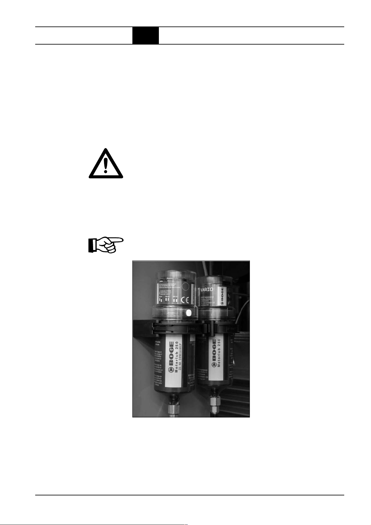
Maintenance
5.3 Regular maintenance work
Servicing drive motor
The drive motors have an automatic lubricating device (see figure).
There is a lubricating nipple on the A bearing and B bearing side of the motor.
The lubricating nipple is connected with the automatic lubricating device via
a tube.
The tubes are already filled with grease. When the tubes are replaced, they
must be filled with grease.
The type of grease is indicated on the lubrication unit of the compressor
(see Fig. 5.5 below).
Voltage is supplied from the switch cabinet.
Both LC units (LC = lubrication canister) are designed for 1 year in threeshift operation. After one year, the canisters must be replaced because
of lubricant ageing, no matter how much lubricant they have.
So as to comply with the necessary lubricating deadlines, the coding switches
"VOL" and "TIME" of the drives are preset in the factory according to table
7.2 of the Operating Instructions for CONTROL TIME.
Set values:
– LC unit S250 for A bearing: 2.89 cm³/ per 100 operating hours
For information regarding operating and maintenance to CONTROL TIME,
please read enclosed operating instructions.
Fig. 5.5: Automatic lubricating device CONTROL TIME
BOGE Operating instructions for S 40-2...S 341 / SF 40-2...SF 220 series screw compressors
Wartung.pm6.5 - USA
Page 5.9

Maintenance
5.3 Regular maintenance work
Changing the V-belt
Check: – 1x per year for damage.
Change: – At visible damage.
The BOGE GM drive system automatically adjusts the V-belt to the correct
V-belt tension in any operating mode.
Maintenance of the V-belt drive is limited to the above mentioned work.
– Switch off the compressor using the OFF button.
DANGER: Risk of injury!
Switch off the main switch and secure it against unintentional switch-on.
Slacken the V-belts:
– Remove cladding on the maintenance side as well as the belt protection.
– Secure screw head of the tensioning device with NW 27 spanner to
prevent it from turning.
– Turn locknut clockwise. Raise the motor in arrow direction until the
V-belts are fully slackened.
Change the V-belts:
– Remove the slackened belts from the belt pulleys.
– Fit new V-belts on the belt pulleys on the motor and compressor.
CAUTION!
The new V-belts must be of precisely the same length.
Only change the V-belts as a complete set!
Tensioning the V-belts:
– Lower the motor again. For this purpose, secure screw head against
turning, then turn locknut counterclockwise and lock by means of the
screw head. The V-belts are automatically correctly tensioned by the
BOGE GM drive system.
– Fit belt protection.
– Reattach cladding on the maintenance side.
3
4
5
Page 5.10
Fig. 5.6: The BOGE GM
drive system
Note:
Note: Demonstration example. Compressor may only be operated with the switch cabinet
closed and all panels fitted.
BOGE Operating instructions for S 40-2...S 341 / SF 40-2...SF 220 series screw compressors
Wartung.pm6.5 - USA

Maintenance
5.3 Regular maintenance work
Setting GM –
Belt tensioning device
S 40-2 – S 341
SF 40-2 – SF 220
blue
inch
Setting
sealed
Model Pressure Setting
+0/– 0.04
psig inch
S 40-2 / SF 40-2 100 / 115 / 125 / 150 / 190 4.4 / 4.4 / 4.4 / 4.4 / 4.4
S 50-2 100 / 115 / 125 / 150 / 190 4.4 / 4.4 / 4.4 / 4.4 / 4.4
S 60-2 / SF 60-2 100 / 115 / 125 / 150 / 190 4.4 / 4.4 / 4.4 / 4.4 / 4.4
S 61-2 100 / 115 / 125 / 150 / 190 4.4 / 4.4 / 4.4 / 4.4 / 4.4
S 75-2 100 / 115 / 125 / 150 / 190 4.4 / 4.4 / 4.4 / 4.4 / 4.4
S 100-2 / SF 100-2 100 / 115 / 125 / 150 / 190 4.4 / 4.4 / 4.4 / 4.4 / 4.4
S 101 100 / 115 / 125 / 150 / 190 4.4 / 4.4 / 4.4 / 4.4 / 4.4
S 125 100 / 115 / 125 / 150 / 190 3.6 / 3.8 / 3.8 / 3.7 / 3.9
S 150 / SF 150 100 / 115 / 125 / 150 / 190 3.6 / 3.4 / 3.4 / 3.4 / 3.0
S 151 100 / 115 / 125 / 150 / 190 3.6 / 3.4 / 3.4 / 3.4 / 3.0
S 180 100 / 115 / 125 / 150 / 190 3.6 / 3.4 / 3.4 / 3.4 / 3.5
S 220 / SF 220 100 / 115 / 125 / 150 / 190 3.5 / 3.3 / 3.3 / 3.4 / 3.5
S 271 100 / 115 / 125 / 150 / 190 4.0 / 4.0 / 3.8 / 3.8 / 4.8
S 341 100 / 115 / 125 / 150 / 190 3.5 / 3.5 / 3.2 / 3.2 / 4.6
The settings shown in the table are fixed by the manufacturer and may not
be changed. Slight deviations are allowed and compensated by the GM
drive system.
The current settings are also shown on the GM drive system. With special
versions the settings on the sticker may deviate from the standard values.
If the spring is not pre-tensioned at the set measure, the measure must be
reduced until the spring is slightly pretensioned (to prevent the spring clapping).
Checking the oil level,
topping up oil
Check: – Prior to commissioning/start-up of the compressor.
– Then every 1000 operating hours,
however at least once a year.
Topping up: – When the oil level has dropped below the "min" mark
(see sketch).
CAUTION!
Always use the same oil type when topping up.
Never mix different oil types and brands.
BOGE Operating instructions for S 40-2...S 341 / SF 40-2...SF 220 series screw compressors
Wartung.pm6.5 - USA
Page 5.11

Maintenance
5.3 Regular maintenance work
– Switch off the compressor using the OFF button.
DANGER: Risk of injury!
Switch off the main switch and secure it against unintentional switch-on.
– Close ball valve at the compressed air outlet.
– Vent the compressor (as described in the beginning of the chapter).
The system pressure gauge must indicate a pressure of 0 psig.
– Wait approx. 3 minutes to permit the oil to settle.
– Remove cladding on the maintenance side.
DANGER: Risk of injury!
Danger of burning due to hot oil!
– Remove plug of oil filling socket .
– Check oil level.
The oil level must not drop below the "min" mark (see sketch).
– If necessary, top up with oil to the lower edge of the thread ("max." mark)
on the oil filling socket.
– Screw plug with viton seal back in.
– Reattach clading on the maintenance side.
– Open ball valve at the compressed air outlet.
Page 5.12
1
2
Fig. 5.7: Checking the oil level, topping up with oil Note:
Note: Demonstration example. Compressor may only be operated with the switch cabinet
closed and all panels fitted.
BOGE Operating instructions for S 40-2...S 341 / SF 40-2...SF 220 series screw compressors
Wartung.pm6.5 - USA

Maintenance
5.3 Regular maintenance work
Changing the oil filter
Change: – After 3000 operating hours,
however, no later than after one year.
– With each oil change!
– Switch off the compressor using the OFF button.
DANGER: Risk of injury!
Switch off the main switch and secure it against unintentional switch-on.
– Close ball valve at the compressed air outlet.
– Take off safety warm air hood and open safety sound insulation hood.
– Vent the compressor (as described in the beginning of the chapter).
The system pressure gauge must indicate a pressure of 0 psig.
– Wait approx. 3 minutes to permit the oil to settle.
– Remove cladding on the maintenance side.
DANGER: Risk of injury!
Danger of burning due to hot oil!
– Unscrew soiled oil filter by hand or use a strap wrench, turning counter-
clockwise.
Catch the draining oil and dispose of properly according to environmental
regulations.
– Fill the new oil filter with compressor oil.
– Lightly oil the sealing ring of the new oil filter.
– Screw in new oil filter by hand, turning clockwise.
– Close safety sound insulation hood.
CAUTION!
Do not use tools to screw in the new oil filter!
You might damage the oil filter or its sealing ring.
A hand tight seating of the oil filter is sufficient.
– Close safety sound insulation hood and reattach cladding on the mainte-
nance side.
– Open ball valve at the compressed air outlet.
– Switch on the compressor and heat up to operating temperature.
– Subsequently, check the oil filter for leaks once again and tighten by hand,
if necessary (Procedure as described above).
DANGER: Risk of injury!
Switch off the main switch and secure against unintentional switch-on.
– Check the oil filter for leaks and tighten by hand, if necessary.
– Check oil level.
Top up oil losses, if any.
BOGE Operating instructions for S 40-2...S 341 / SF 40-2...SF 220 series screw compressors
Wartung.pm6.5 - USA
Page 5.13

Maintenance
5.3 Regular maintenance work
3
Fig. 5.8: Changing the oil filter Note:
Changing
the oil separator
Change: – When the difference between supply and system pressure
exceeds 12 psig.
– When warning message "8" appears on the control system
display (if option is installed).
– After 3000 operating hours,
however, no later than after one year.
NOTICE:
If the specified maintenance intervals are not observed, the oil separators might become blocked. In this case, the differential pressure will
increase until the safety valve blows.
– Switch off the compressor using the OFF button.
DANGER: Risk of injury!
Switch off the main switch and secure it against unintentional switch-on.
– Close ball valve at the compressed air outlet.
– Open safety sound insulation hood.
– Vent the compressor (as described in the beginning of the chapter).
The system pressure gauge must indicate a pressure of 0 psig.
– Wait approx. 3 minutes to permit the oil to settle.
Note: Demonstration example. Com-
pressor may only be operated
with the switch cabinet closed
and all panels fitted.
Page 5.14
BOGE Operating instructions for S 40-2...S 341 / SF 40-2...SF 220 series screw compressors
Wartung.pm6.5 - USA

Maintenance
5.3 Regular maintenance work
DANGER: Risk of injury!
Danger of burning due to hot oil!
– Remove cladding on the maintenance side.
– Unscrew soiled oil separators by hand or use a strap wrench, turning
counterclockwise.
– Catch the draining oil and dispose of properly according to environmental
regulations.
– Lightly oil the sealing rings of the new oil separator.
– Screw in new oil separators by hand, turning clockwise.
CAUTION!
Do not use tools to screw in the new oil separators!
You might damage the oil separators or their sealing rings.
A hand tight seating of the oil separators is sufficient.
– Close safety sound insulation hood.
– Reattach cladding on the maintenance side.
– Open ball valve at the compressed air outlet.
– Switch on the compressor and heat up to operating temperature.
– Check the oil filter for leaks once again (Procedure as described above).
DANGER: Risk of injury!
Switch off the main switch and secure it against unintentional switch-on.
– Check the oil separators for leaks and tighten by hand, if necessary.
4
Fig. 5.9: Changing the oil separators Note:
Note: Demonstration example. Compressor may only be operated with the switch cabinet
closed and all panels fitted.
BOGE Operating instructions for S 40-2...S 341 / SF 40-2...SF 220 series screw compressors
Wartung.pm6.5 - USA
Page 5.15

Maintenance
5.3 Regular maintenance work
Oil change
Change: – After 9000 operating hours,
however, at the latest after two years.
– For other types of oil the appropriate oil change intervals
must be complied with.
NOTICE:
The service life of the oil, the oil filter and oil separators is reduced under the
following conditions:
– When the compressor is operated at extreme ambient temperatures.
– When the intake air is extremely soiled.
Building up a pressure cushion
The combined compressed air / oil receiver is located at the lowest point of
the system. Therefore, a light pressure cushion (approx. 30 psig system
pressure) must be applied to drain the oil. This pressure cushion forces the
oil through the drain hose into a suitable collecting basin.
DANGER: Risk of injury!
Switch off the main switch and secure it against unintentional switch-on.
– Screw cap nut onto the vent hole of the solenoid valve on the suction
controller by hand.
The cap nut (M8) is located in the storage compartment of the switch
cabinet.
CAUTION!
Never use any tools to screw on the cap nut!
Damage af the solenoid valve might result.
– Switch on the compressor again and allow it to start up.
If necessary, let out some air from the compressed air receiver until the
switch-on pressure of the compressor is reached.
– Switch off the compressor at approx. 30 – 44 psig system pressure using
the EMERGENCY-OFF-button.
DANGER: Risk of injury!
Switch off the main switch and secure it against unintentional switch-on.
– Slowly loosen cap nut until compressed air escapes.
– Let off compressed air until the system pressure gauge shows a residual
pressure of approx. 30 psig.
– Tighten cap nut by hand.
DANGER: Risk of injury!
Danger of burning due to hot oil!
Draining old oil
– Place the oil drain hose into a suitable container .
– Slowly open the stop valve.
The pressure cushion forces the oil into the container.
– Once the compressed air/oil receiver has been completely drained, close
the stop valve.
– Remove the cap nut from the solenoid valve.
Page 5.16
BOGE Operating instructions for S 40-2...S 341 / SF 40-2...SF 220 series screw compressors
Wartung.pm6.5 - USA

Maintenance
5.3 Regular maintenance work
– Remove oil filler screw on the compressed air/oil cooler and drain the
residual oil (max. 5 litres) into a suitable container.
– Reinsert the oil filler screw together with a new copper sealing ring.
– Change oil filter (Procedure as described above).
– Change oil separators (Procedure as described above).
Filling with new oil:
– Fill up to the edge of the thread of the filling socket (max.).
(Procedure as described above).
CAUTION!
After each oil change you have to fill a small quantity of oil into the suction
controller before starting the compressor.
For oil quantity and procedure see chapter "Commissioning following extended
stoppages".
CAUTION!
Always fill with the same oil type as previously used.
Never mix different oil types and brands.
The oil circuit must be flushed prior to changing the oil type.
– Close safety sound insulation hood.
– Open ball valve at the compressed air outlet.
– Reattach cladding on the maintenance side.
– Conduct trial run.
5
Fig. 5.10: Solenoid valve Note:
on the intake controller with
the cap nut screwed on
DANGER: Risk of injury!
Switch off the main switch and secure it against unintentional switch-on.
– Check the oil filters and oil separators for leaks and tighten by hand,
if necessary (procedure as described above).
– Check oil level (procedure as described above).
Top up oil losses, if any.
7
6
Fig. 5.11: Note:
Drain off old oil from
air/oil separator vessel
Fig. 5.12: Note:
Drain off residual oil from
oil cooler
Note: Demonstration example. Compressor may only be operated with the switch cabinet closed and all panels fitted.
BOGE Operating instructions for S 40-2...S 341 / SF 40-2...SF 220 series screw compressors
Wartung.pm6.5 - USA
Page 5.17

Maintenance
5.3 Regular maintenance work
Flushing the oil circuit
Cleaning the
compressed air / oil
cooling unit
(air cooling)
Flushing the oil circuit with clean oil becomes necessary:
– When the oil is excessively soiled.
– Prior to changing the oil type.
CAUTION!
Detailed information as to the flushing with BOGE oils you can obtain from
the following service number.
770 - 874 -1570
Cleaning: – After 1500 operating hours,
however, at the latest after one year.
The service life of the compressed air/oil cooling unit depends on the
degree of soiling (dust, oil vapour) of the suctioned cooling air. Extreme
external soiling of the cooling unit leads to an increased temperature
in the oil circuit.
– Switch off the compressor using the OFF button.
DANGER: Risk of injury!
Switch off the main switch and secure it against unintentional switch-on.
– Remove cladding on the maintenance side.
– Unscrew the maintenance flap on the air guidance box.
– Remove accumulated soiling with a fibre brush.
CAUTION!
Do not use any sharp objects for cleaning!
These could damage the cooling unit!
– Blow down the dirt with compressed air in the opposite direction to the
normal cooling air flow. Clean out the dirt using an industrial vacuum
cleaner (see Fig.).
If the cooling unit is excessively soiled (cleaning is no longer possible with
compressed air), have it disassembled and cleaned by BOGE service.
Page 5.18
BOGE Operating instructions for S 40-2...S 341 / SF 40-2...SF 220 series screw compressors
Wartung.pm6.5 - USA

Maintenance
5.3 Regular maintenance work
1
Proportional controller
(option for S-series)
1
2
For water-cooled versions
a cleaning is not necessary
Fig. 5.13: Cleaning the compressed air/oil cooling unit Note:
Check: – After approx. 3000 operating hours,
however, at least once a year.
1. Setting the operating pressure sensor
Switch-on pressure: P
Switch-off pressure: P
= Final compression pressure – 14 psig.
min
= Final compression pressure.
max
2. Setting the proportional controller
Displace the control range of the proportional controller by turning cap .
– Increase pressure level:
Turn cap clockwise.
– Reduce pressure level:
Turn cap counterclockwise.
Always set the proportional controller higher than the bottom operating pressure value (P
min
)!
3. Pressure switch for infinitely variable capacity control
The low pressure switch for the infinitely variable capacity control limits the
reduction of the delivered quantity and switches the compressor in the event
of less than 50 % delivered quantity into idling operation or off.
Note: Demonstration example. Compressor may only be operated with the switch cabinet
closed and all panels fitted.
BOGE Operating instructions for S 40-2...S 341 / SF 40-2...SF 220 series screw compressors
Wartung.pm6.5 - USA
Page 5.19

Maintenance
5.3 Regular maintenance work
Checking
the safety valve
DANGER: Risk of injury!
Because a hot air-oil mixture will escape when checking the safety valve
with running compressor only trained personnel or specialists should carry
out this work!
Check: – After approx. 3000 operating hours,
however, at least once a year.
Check safety valve by opening the screw plug .
DANGER: Risk of injury!
Danger of burning due to hot oil!
Take extreme care when checking the safety valve with the compressor
running taking all safety measures into consideration. Wear eye protection.
A hot air-oil mixture escapes when opening!
– Open the threaded plug counterclockwise.
The compressed air escapes.
– Tighten the threaded plug by turning clockwise.
Fig. 5.14: check safety valve
1
Page 5.20
BOGE Operating instructions for S 40-2...S 341 / SF 40-2...SF 220 series screw compressors
Wartung.pm6.5 - USA
Maintenance
5.4 Spare parts and optional equipment
List of spare and
wearing parts
(for maintenance)
Designation
Filter mat for supply air filter
Compressor oil Syprem 8000 S
Set of V-belts
Lubrication for drive motor bearings
Maintenance kit consisting of:
oil filter, oil separator, suction filter cartridge, gaskets, nozzle with dirt catch
Wearing part kit consisting of:
oil regulator, intake regulator, minimum pressure valve
Solenoid valve
NOTICE:
When ordering, please specify the data on the type plate:
– Type
– Year of manufacture
– Machine number
BOGE Operating instructions for S 40-2...S 341 / SF 40-2...SF 220 series screw compressors
Wartung.pm6.5 - USA
Page 5.21

Maintenance
Page 5.22
BOGE Operating instructions for S 40-2...S 341 / SF 40-2...SF 220 series screw compressors
Wartung.pm6.5 - USA

Appendix
Air cooled version, standard
6.1 Flow chart
Air IN
1 = Suction filter
2 = Maintenance display (from 30 kW)
3 = Vacuum switch
(for suction filter monitoring) *
4 = Suction controller
5 = Ventilation and regulation control valve
7 = Drive motor
8 = Compressor air end
9 = Sensor for final compression temperature
10 = Combined compressed air/oil receiver
11 = Oil separator
12 = Safety valve
16 = Thermostatic oil control valve
17 = Oil cooler
18 = Oil filter
19 = Differential pressure switch
(for oil filter monitoring) *
20 = Oil throttle
21 = Minimum pressure check valve
22 = Compressed air after-cooler
Compressed air
OUT
23 = Pressure sensor system pressure
24 = Pressure sensor network pressure
25 = Stop valve, compressed air outlet
27 = Stop valve, oil drainage
28 = Check valve drainage line (up to 75 kW)
29 = Proportional controller *
30 = Diff. pressure switch for prop. controller *
31 = 3/2-way solenoid valve for prop. contr. *
(with standard control passage here)
37 = Display of F.a.d. for prop. controller *
42 = 3/2-way solenoid valve for suction control
regulation *
43 = Double check valve*
(Pos. 42 + 43 = rapid-start valve)
44 = Double check valve *
(Monitoring of rotational direction)
* = Option
BOGE Operating instructions for S 40-2...S 341 / SF 40-2...SF 220 series screw compressors
Fliess.pm6.5 - USA
Page 6.1

Appendix
6.1 Flow chart
Water cooled version, serial connection – parallel connection
Air IN
Water OUT
Water IN
* Parallel connection Serial connection
1 = Suction filter
2 = Maintenance display (from 30 kW)
3 = Vacuum switch
(for suction filter monitoring) *
4 = Suction controller
5 = Air relief and regulation control valve
7 = Drive motor
8 = Compressor air end
9 = Sensor for final compression temperature
10 = Combined compressed air/oil receiver
11 = Oil separator
12 = Safety valve
16 = Thermostatic oil control valve
17 = Oil cooler
18 = Oil filter
19 = Differential pressure switch
(for oil filter monitoring) *
20 = Oil throttle
21 = Minimum pressure check valve
22 = Compressed air after-cooler
23 = Pressure sensor system pressure
24 = Pressure sensor network pressure
25 = Stop valve, compressed air outlet
Compressed
air OUT
Water OUT
Water IN
Compressed
air OUT
27 = Stop valve, oil drainage
28 = Check valve drainage line (up to 75 kW)
29 = Proportional controller*
30 = Diff. pressure switch for prop. controller *
31 = 3/2-way solenoid valve for prop. contr. *
(with standard control passage here)
32 = 2/2-way solenoid valve
33 = Control valve water supply (preadjusted)
34 = Control valve water supply (preadjusted)
37 = Display of F.a.d. for prop. controller *
42 = 3/2-way solenoid valve for suction control
regulation *
43 = Double check valve*
(Pos. 42 + 43 = rapid-start valve)
44 = Double check valve *
(Monitoring of rotational direction)
To be provided by customer:
35 = Dirt trap
36 = Stop valve
* = Option
Page 6.2
BOGE Operating instructions for S 40-2...S 341 / SF 40-2...SF 220 series screw compressors
Fliess.pm6.5 - USA

Appendix
6.1 Flow chart
Air cooled version, frequency-controlled
Air IN
1 = Suction filter
2 = Maintenance display
3 = Vacuum switch (for suction filter monitoring) *
4 = Suction controller
5 = Air relief and regulation control valve
6 = Pressure switch (for rotational direction,
system relief and V-belt monitoring)
7 = Drive motor
8 = Air end
9 = Final compression temperature display and switch
10 = Combined compressed air/oil receiver
11 = Oil separator
12 = Safety valve
13 = Differential pressure switch
(for oil separator monitoring) *
14 = System pressure switch
(for system pressure build-up and monitoring) *
15 = Safety pressure switch (for pressure limitation) *
16 = Thermostatic oil control valve
Compressed
air OUT
17 = Oil cooler
18 = Oil filter
19 = Differential pressure switch
(for oil filter monitoring) *
20 = Oil throttle
21 = Minimum pressure check valve
22 = Compressed air after-cooler
23 = Operating pressure switch
24 = Pressure gauge (line pressue)
24.1= Pressure gauge (system pressure)
25 = Stop valve, compressed air outlet
27 = Stop valve, oil drainage
27.1= Stop valve, oil drainage
(oil cooler, 75 – 250 kW)
28 = Check valve drainage line
(to 75 kW)
* = Option
BOGE Operating instructions for S 40-2...S 341 / SF 40-2...SF 220 series screw compressors
Fliess.pm6.5 - USA
Page 6.3

Appendix
Motor
mainte-
6.2 List of maintenance and service work
nance
unit
Cooling
cleaning
Oil
separator
**
Oil-
level
Oil-
filter
*
filter
Intake
ture
Tempera-
Please note the completed maintenance work in the respective columns
System
pressure
Ch = Change
** C = Check
Page 6.4
Line
pressure
hours
Operating
Date Remarks
Ch = Change
* Cl = Cleaning
BOGE Operating instructions for S 40-2...S 341 / SF 40-2...SF 220 series screw compressors
Fliess.pm6.5 - USA

Appendix
Motor
mainte-
6.2 List of maintenance and service work
nance
unit
Cooling
cleaning
Oil
separator
**
Oil-
level
Oil-
filter
*
filter
Intake
ture
Tempera-
Please note the completed maintenance work in the respective columns
System
pressure
Ch = Change
** C = Check
Line
pressure
hours
Operating
Date Remarks
BOGE Operating instructions for S 40-2...S 341 / SF 40-2...SF 220 series screw compressors
Fliess.pm6.5 - USA
Ch = Change
* Cl = Cleaning
Page 6.5

Appendix
Motor
mainte-
6.2 List of maintenance and service work
nance
unit
Cooling
cleaning
Oil
separator
**
Oil-
level
Oil-
filter
*
filter
Intake
ture
Tempera-
Please note the completed maintenance work in the respective columns
System
pressure
Ch = Change
** C = Check
Page 6.6
Line
pressure
hours
Operating
Date Remarks
Ch = Change
* Cl = Cleaning
BOGE Operating instructions for S 40-2...S 341 / SF 40-2...SF 220 series screw compressors
Fliess.pm6.5 - USA
 Loading...