


Operating instructions
Oil-free
scroll compressors
Series
EO 6...EO 6 TR
EO 11...EO 16
EO 17...EO 22
EO 17 D...EO 22 D
Separate instructions:
Compressor control
Refrigerant compressed air dryer (DS)
Compressed air treatment


Operating instructions
for oil-free
scroll compressors
– EO 6 / EO 6 D / EO 6 R / EO 6 DR / EO 6 TR ( 5.5 kW)
– EO 11 / EO 11 D (11 kW)
– EO 16 / EO 17 / EO 17 D (16.5 kW)
– EO 22 / EO 22 D (22 kW)
IMPORTANT!
READ CAREFULLY BEFORE USE
RETAIN FOR FUTURE REFERENCE
BOGE KOMPRESSOREN
Otto Boge GmbH & Co. KG
Postfach 10 07 13
33507 Bielefeld, Germany
Otto-Boge-Straße 1-7
33739 Bielefeld, Germany
Phone: +49 5206 601-0
Fax: +49 5206 601-200
E-mail: info@boge.com
Net: www.boge.com
Translation of original operating instructions
Version: 02 / 2017
No. 596.1393.01
Nominal price: € 5.00
BOGE Operating instructions for scroll compressors, series EO 6...EO 22 D Page I


Table of contents
Table of contents
Part 1:
General
Part 2:
Safety
1.1 Who are these operating instructions aimed at? ........................ 1
1.2 Content of these instructions........................................................ 1
1.3 Other important documents .......................................................... 2
1.4 Guide for reading............................................................................ 2
Symbols and typographic aids.......................................................... 2
Structure of warning notices ............................................................. 3
1.5 Warranty and service ..................................................................... 4
Limitation of liability........................................................................... 4
Transport damage ............................................................................ 4
Service.............................................................................................. 4
Data on the rating plate .................................................................... 5
1.6 System subject to monitoring ....................................................... 5
2.1 General safety information ............................................................ 7
Intended use ..................................................................................... 7
Reasonably foreseeable misuse....................................................... 7
Responsibility of the operator ........................................................... 8
Personnel requirements.................................................................... 9
Special warning notices .................................................................. 10
2.2 Safety information for operating the compressor ..................... 11
Electrical equipment of the compressor.......................................... 12
Scroll compressor, drive, air system............................................... 13
Lubricant and refrigerant................................................................. 14
2.3 Servicing safety information ....................................................... 14
Safety information for maintenance and repair of the dryer
(EO...D)........................................................................................... 15
Part 3:
Product description
BOGE Operating instructions for scroll compressors, series EO 6...EO 22 D Page III
3.1 How the compressor works......................................................... 17
Compression process ..................................................................... 17
Cooling air requirement .................................................................. 18

Table of contents
3.2 Control of the compressor........................................................... 19
Net pressure ................................................................................... 19
Operating states ............................................................................. 19
Operating modes ............................................................................ 19
3.3 Safety and monitoring devices.................................................... 19
General ........................................................................................... 19
Emergency stop function / main switch (mains disconnecting
device) ............................................................................................ 20
Temperature monitoring ................................................................. 20
Decompression............................................................................... 20
3.4 Technical data............................................................................... 22
3.5 How the DS dryer works .............................................................. 26
DS refrigerant dryer ........................................................................ 26
3.6 How the DRL 6-2 dryer works ...................................................... 27
Device overview.............................................................................. 27
Functional principle of the DRL 6-2 ................................................ 28
Part 4:
Installation
3.7 Regulating the DRL 6-2 integrated dryer .................................... 28
Compressed air side....................................................................... 28
Refrigerant side .............................................................................. 28
Pressure dew point regulation ........................................................ 29
Condensate drainage ..................................................................... 29
4.1 Transporting the compressor...................................................... 31
General ........................................................................................... 31
Intermediate storage of the compressor before installation ............ 31
Transporting the compressor using a forklift truck .......................... 32
Transporting the compressor with a crane ..................................... 32
4.2 Installing the compressor ............................................................ 33
Specifications for the compressor room ......................................... 33
Checking the scope of the delivery ................................................. 36
Positioning the compressor ............................................................ 36
Removing the transport locks ......................................................... 36
Belt tension ..................................................................................... 36
Installation conditions for compressed air receivers ....................... 37
Installation conditions for DRL 6-2 and DS dryers.......................... 37
4.3 Assembly work ............................................................................. 38
General ........................................................................................... 38
4.4 Establishing the connections...................................................... 38
Connecting the compressor to the compressed air network........... 40
1Establishing the electrical connection ........................................... 40
Condensate outlet connection (EO...D, EO...DR)........................... 41
Page IV BOGE Operating instructions for scroll compressors, series EO 6...EO 22 D

Table of contents
Part 5:
Commissioning
Part 6:
Servicing and
maintenance
5.1 Commissioning the compressor................................................. 43
Checking the installation conditions................................................ 43
Checking the pressure settings ...................................................... 44
Checking the rotation direction of the drive and fan motors ........... 44
Checking the leak tightness of the compressed air pipes............... 45
Opening the shut-off valves ............................................................ 45
Conducting a test run...................................................................... 45
5.2 Shutting down / recommissioning the compressor .................. 46
Shutting down the compressor for prolonged periods .................... 46
Recommissioning the compressor after a prolonged period of
inactivity .......................................................................................... 46
Refrigerant compressed air dryer ................................................... 46
5.3 Operating the DRL 6-2 DL dryer .................................................. 47
6.1 Basic information on servicing ................................................... 49
Servicing safety information............................................................ 49
Servicing by BOGE customer service recommended..................... 52
Servicing overviews ........................................................................ 52
Maintenance Intervals..................................................................... 56
Maintenance work between fixed servicing intervals...................... 56
Maintenance work at fixed servicing intervals ................................ 57
Maintenance work on the dryer (EO...D) ........................................ 58
General information on lubricants and refrigerants......................... 58
Disposing of used operating materials and condensates ............... 59
Pressure hoses............................................................................... 59
Spare and wearing parts................................................................. 59
6.2 Performing maintenance work between fixed servicing
intervals ......................................................................................... 60
Monthly: Check / replace supply air filter for switch cabinet
ventilation........................................................................................ 60
Monthly: checking / cleaning the suction filter ................................ 60
Every 1,500 operating hours: Cleaning the cooler.......................... 61
Every 5,000 or 10,000 operating hours: Cleaning the fan .............. 63
6.3 Having maintenance work performed at fixed servicing
intervals ......................................................................................... 65
Every 3,000 operating hours:
Changing the suction filter cartridge ............................................... 65
Every 3,000 operating hours / annually:
Function check of the safety valves................................................ 65
Every 3,000 operating hours / annually:
Checking the V-belts....................................................................... 66
Every 3,000 operating hours / annually:
Checking the non-return valves ...................................................... 66
Every 5,000 / 10,000 operating hours:
Scroll compressor servicing............................................................ 66
BOGE Operating instructions for scroll compressors, series EO 6...EO 22 D Page V

Table of contents
Every 10,000 operating hours: Replacing the V-belts .................... 66
Every 15,000 / 20,000 operating hours:
Replacing the scroll compressor..................................................... 68
6.4 Special maintenance work........................................................... 68
Drive motors with permanent lubrication ........................................ 68
6.5 Maintenance work on the DRL DL dryer 6-2 .............................. 68
Daily checks.................................................................................... 68
Weekly maintenance ...................................................................... 68
Annual maintenance ....................................................................... 68
6.6 Disposal after dismantling or replacement of parts.................. 69
6.7 Spare parts and additional equipment ....................................... 70
List of spare and wearing parts (for maintenance) ......................... 70
Spare parts for the DRL 6-2 DL dryer ............................................. 70
Spare parts for the DS dryer ........................................................... 70
List of available additional equipment............................................. 70
Part 7:
Remedying faults
Part 8:
Appendix
7.1 Basic information on remedying faults ...................................... 71
Compressor faults........................................................................... 72
Refrigerant dryer and treatment faults (EO...D) .............................. 73
8.1 Guidelines and standards ............................................................ 75
8.2 Application of the Pressure Equipment Directive ..................... 75
Scope.............................................................................................. 75
Classification and assessment of pressurised components ........... 76
Outcome of the assessment ........................................................... 76
Installation in compressed air systems ........................................... 76
8.3 Pneumatic circuit diagrams......................................................... 76
Pneumatic circuit diagram for EO 6, air-cooled .............................. 77
Pneumatic circuit diagram for EO 6 D, air-cooled........................... 78
Pneumatic circuit diagram for EO 6 R, air-cooled........................... 79
Pneumatic circuit diagram for EO 6 DR, air-cooled ........................ 80
Pneumatic circuit diagram for EO 6 TR, air-cooled ........................ 81
Pneumatic circuit diagram for EO 11 (D), air-cooled ...................... 82
Pneumatic circuit diagram for EO 16, air-cooled ............................ 83
Pneumatic circuit diagram for EO 17 (D), air-cooled ...................... 84
Pneumatic circuit diagram for EO 22 (D), air-cooled ...................... 85
8.4 List of maintenance work performed .......................................... 86
Page VI BOGE Operating instructions for scroll compressors, series EO 6...EO 22 D

General 1.1 Who are these operating instructions aimed at?
Part 1: General 1.1 Who are these operating instructions aimed at?
These instructions are aimed at end customers of BOGE who have purchased
a scroll compressor and wish to operate it.
In addition to reading these instructions, the user must meet the following prerequisites in order to ensure professional operation of the compressor. S / he
must:
– have an understanding of the control and of the accompanying operating
instructions.
– have an understanding of the accompanying operating instructions for the
additional components.
– be classified as skilled personnel or trained personnel with technical back-
ground knowledge in the field of compressed air technology.
1.2 Content of these instructions
These operating instructions deal exclusively with the functionality and operation of a BOGE type EO scroll compressor.
The prerequisite for safe operation of the scroll compressor is adherence to all
the stipulated safety information and directions for use. Personnel must therefore have carefully read and understood these operating instructions before
carrying out any work. In addition, the accident prevention regulations applicable in the location where the compressor is used as well as the general safety
regulations must be observed. The illustrations in these instructions are provided for basic understanding and may differ from the actual version of the
product. No claims can be made on this basis.
The following content and work descriptions do not (or only to a limited extent)
form part of these instructions:
– Work on the electrical installations, e.g. the electrical commissioning or
repairs to the control.
– Work on the DS refrigerant dryer, on the compressed air treatment com-
ponents or on accessories.
Work on the electrical installations may only be carried out by an authorised
and qualified electrician or BOGE Service personnel.
BOGE recommends having the control, compressor(s) and accessories set up
and commissioned by BOGE Service personnel. Repair and maintenance
work on the compressor should also be carried out by BOGE Service personnel.
BOGE Operating instructions for scroll compressors, series EO 6...EO 22 D Page 1

General 1.3 Other important documents
1.3 Other important documents
– Lubricant and refrigerant safety data sheets (EO...D)
– Data sheets / documentation on the control and accessories
– Documentation for compressed air receiver (EO 6 R, EO 6 DR, EO 6 TR)
– Documentation for DS refrigerant dryer (EO 6 DR, EO 17 D, EO 22 D)
– Documentation for condensate drains and cyclone separator
1.4 Guide for reading
Symbols and typographic aids
Symbol
– Information 1
– Information 2
– Information 3
Action
or
● Action
1. Action 1
2. Action 2
3. Action 3
Æ Result of action Result
Meaning
Tips and additional information on
optimum operation
Tips and information that help you to
use the compressor in an optimum
manner are indicated by the symbol
shown.
List
Important information is listed clearly.
Directions for use I
Especially important directions for use
with one action are indicated by the
symbol shown.
Directions for use II
Directions for use with several actions
are numbered and must be carried out
in the specified sequence.
The outcome that will follow an action
is indicated by the arrow shown.
(1)
(2)
(3)
Page 2 BOGE Operating instructions for scroll compressors, series EO 6...EO 22 D
Figures
Figures may be divided into areas.
The individual areas are numbered.

General 1.4 Guide for reading
Structure of warning notices
Signal words
Signal word Meaning
DANGER Warns of a danger to persons that will imminently lead
to serious injury or death.
WARNING Warns of dangers to persons that could lead to serious
injury or death.
CAUTION Warns of dangers to persons that could lead to moderate
or minor injuries.
ATTENTION Warns of property damage.
Warning sign
The following general warning sign is used in this document:
Warning sign Meaning
Warns of a hazardous area.
Warning notice design
Warning notices are a combination of signal words, warning signs and information. They are structured as follows:
SIGNAL WORD
Type of danger
Source of the danger and consequences if the warning notice is not observed.
Î How to avoid the danger.
BOGE Operating instructions for scroll compressors, series EO 6...EO 22 D Page 3

General 1.5 Warranty and service
1.5 Warranty and service
Limitation of liability
Transport damage
The manufacturer accepts no liability for direct or consequential damages due
to improper operation or servicing on the basis of the information contained
in these instructions. The product must only be operated by persons who are
familiar with the operating instructions, the product, and national laws, ordinances and regulations on work, safety and accident prevention.
We do not accept any liability for personal injury or property damage caused
by untrained persons, or by non-compliance with the regulations on work,
safety and accident prevention.
No claims for the modification of products that have already been supplied
may be made on the basis of the information, illustrations and descriptions in
this manual.
For your own safety, only use original spare parts and accessories. We do not
assume any liability for the use of other products and any consequential damage.
– Check the delivery for transport damage and completeness.
– Document defects and damage in writing immediately.
– Take photographs of damaged components.
Submit the written damage report.
BOGE accepts no liability for breakage or damage during transport. Please
check the item immediately after delivery and make a complaint to the last
carrier about any damage – even if the packaging is not damaged. In order to
secure your claim for damages against the shipping company, we would advise you to temporarily leave the delivery items and packaging materials in the
condition in which you found them when you identified the damage.
Please submit all other complaints to us within six days of receiving the delivery.
Service
To avoid delays, always provide the following
data for your compressor when submitting enquiries:
–Type
– Year of manufacture
–Number
Should you have any questions about this product, please contact
Technical Support on:
Telephone: +49 5206 601-140
If you require Service assistance, please contact BOGE Service on:
Telephone: +49 5206 601-100
Page 4 BOGE Operating instructions for scroll compressors, series EO 6...EO 22 D

General 1.6 System subject to monitoring
m³/min
bar
kW
Type
Year of manufacture
Maschine number
Volume flow max.
Final compression pressure
Motor speed
rpm
Motor output
Data on the rating plate
Enter the technical data for your compressor from the rating plate or enclosed
data sheet into the figure below. If you have any queries this ensures that you
always have the most important information to hand.
Fig. 1.1: Data on the rating plate
1.6 System subject to monitoring
A compressor is often part of a pressure vessel system, which is subject to
monitoring according to § 14 of the BetrSichV (Ordinance on Industrial Safety
and Health). A system subject to monitoring shall only be put into service for
the first time or after significant modifications if an approved body or a competent person has inspected the system to ensure it is in proper working order
with regards to its assembly, installation, the conditions of erection and safety,
taking into consideration its intended mode of operation.
According to the BetrSichV, the compressed air system shall be subjected to
recurrent inspections by an approved body or competent person.
The operator must determine the inspection intervals within six months of
commissioning and come to an agreement with the approved inspection body.
The recurrent inspections must be arranged within the specified time frame
and documented by the operator.
Operators located outside the Federal Republic of Germany must observe the
national regulations for the country in which the device is used.
BOGE Operating instructions for scroll compressors, series EO 6...EO 22 D Page 5


Safety 2.1 General safety information
Part 2: Safety 2.1 General safety information
Intended use
Reasonably foreseeable misuse
– BOGE compressors, including their additional equipment, are exclusively
intended for the compression and treatment of air for industrial purposes.
The air taken in must not contain any explosive or chemically unstable
gases or vapours.
– The specified operating limits of the compressor may not be exceeded.
– Only operate the compressor in line with the permissible ambient condi-
tions.
– BOGE compressors are designed for stationary operation. Ensure that
they are only installed and operated in clean, dry rooms.
– Operating elements and the control are designed for operation by trained
or qualified personnel.
Type DRL and DS compressed air dryers
– These dryers are only suitable for dehumidifying compressed air.
The compressor must be operated within the technical limits of use. Observe
section “Technical data” on page 22. Non-observance of this data is deemed
improper and poses a risk for the operational safety of the compressor and a
danger to the operating personnel. Severe personal injury and / or property
damage may result.
– Never direct the compressed air produced towards persons. Danger of
death!
– Only use the compressed air produced as breathing air or allow it to come
into contact with food if it has been treated beforehand.
– This BOGE compressor is not explosion-proof. Do not operate in explosive
areas or potentially explosive atmospheres.
– Do not operate the compressor in rooms in which extreme dust, toxic or
flammable vapours and gases may be produced.
The following is not permitted:
– Compressing fluids other than those mentioned under intended use or
compressing fluids loaded with contaminants.
– Exceeding the final compression pressure indicated on the rating plate.
– Altering the safety devices and cladding or putting them out of operation.
– Removing or painting over signs and symbols on the compressor.
– Operation of the compressor by untrained or unauthorised persons.
BOGE Operating instructions for scroll compressors, series EO 6...EO 22 D Page 7

Safety 2.1 General safety information
Responsibility of the operator
Obligations of the operator
The operator is obliged to
– operate the compressor only in a technically perfect, safe-to-operate condi-
tion
– provide a device that automatically switches off the power supply in the
event of a fault, to avoid injury from electric current
– check the completeness and function of the emergency stop device(s) at
regular intervals
– carry out a workplace risk assessment in his area of responsibility and
issue the ensuing operating instructions
– name a person responsible for the safe operation of the machine and the
coordination of all work performed on the machine
– avoid stressful situations when operating the compressor by means of
technological and organisational operations scheduling
– ensure proper workplace lighting is provided at the control section of the
compressor according to the local health and safety regulations
– observe the safety data sheets for the hazardous substances used and
make all information accessible to personnel in accordance with the safety
data sheet
– provide the compulsory personal protective equipment, instruct others on
its use and check that it is being worn at regular intervals
– determine the personnel responsible for various tasks on the machine
– instruct the personnel on a regular basis regarding all obligations concern-
ing the preservation of safety and order at the compressor site
– develop safe technology for the potential dismantling of the construction,
define responsibilities (work safety, supervision, workmanship), supervise
dismantling work and check compliance with the established protective
measures and instructions.
Operation regulations
The compressor unit operator is responsible for ensuring that it is installed,
operated and maintained properly. Operators of work equipment in the Federal Republic of Germany must adhere to the regulations and rules currently
valid for the Industrial Employers' Liability Insurance and Accident Insurance
associations and also the Ordinance on Industrial Safety and Health
(BetrSichV).
When operating the compressor unit outside the Federal Republic of Germany,
the accident prevention regulations of the country in which the compressor is
being operated must be observed in addition to the information contained in
these operating instructions. In the event that measures are required above
and beyond the legal regulations specified in the Federal Republic of Germany
or the information contained in these operating instructions, it is of utmost
importance that these be carried out prior to commissioning the compressor
unit.
Page 8 BOGE Operating instructions for scroll compressors, series EO 6...EO 22 D

Safety 2.1 General safety information
Personnel requirements
General
Only personnel authorised by the operator of the compressor may work with
or on the compressor. The personnel working on the compressor must observe all industrial safety regulations and operating instructions, successfully
carry out their responsibilities, and read and understand the operating instructions. Always wear compulsory personal protective equipment when working
on the compressor.
Only persons who are able to carry out work correctly and reliably and who
meet the following requirements may perform activities on the compressor:
– Only authorised specialists should be instructed to carry out assembly,
installation, service and maintenance work on the compressor.
– Work on the electrical installations may only be carried out by an author-
ised and qualified electrician. The electrical equipment must be disconnected from the mains and precautions taken to prevent it from being
switched back on again.
– The compressor must be operated by trained personnel.
Trained personnel
Trained personnel are persons whom the operator has given detailed information about the tasks assigned to them and the possible dangers.
Qualified personnel / specialist
Skilled personnel are persons who are able to successfully carry out work
assigned to them, recognise possible dangers independently and avoid injury
to persons or damage to property due to their professional training, knowledge
and experience as well as knowledge of the relevant regulations.
Qualified electrician
All work on the electrical system may only be carried out by a qualified electrician. Qualified electricians are persons who are able to successfully carry out
work assigned to them on electrical equipment, recognise possible dangers
independently and avoid injury to persons or damage to property as a result of
electrical current due to their specialist qualifications, knowledge and experience as well as knowledge of the relevant regulations.
Personal protective equipment (PPE)
In general for all work on the compressor
– protective clothing
– slip-resistant safety shoes and
– hearing protection, if applicable,
must be worn.
For special duties
– a protective helmet (for transportation with lifting gear)
– protective goggles (for work on pressurised parts / components)
– chemical-resistant protective gloves (when handling lubricants)
– cut and puncture-resistant protective gloves
must be worn.
Before starting work with operating materials (e.g. lubricating greases) without
wearing chemical-resistant protective gloves, a skin protection cream must be
applied. After finishing the work a skin care product must be applied.
BOGE Operating instructions for scroll compressors, series EO 6...EO 22 D Page 9

Safety 2.1 General safety information
Special warning notices
To indicate particular dangers, the following warning symbols / pictograms are
used alongside warning notices.
Danger due to electric current
...warns of life-threatening dangers due to electric current.
Non-observance of the warning notice can cause serious or fatal injuries.
Activities that follow this warning notice may only be carried out by authorised and qualified electricians.
Danger from hot surfaces and operating materials
...warns of dangers from hot surfaces and operating materials.
Non-observance of the warning notice can result in serious burns.
Activities that follow this warning notice may only be carried out by authorised and qualified personnel.
Danger from automatic restart
...warns of dangers due to an automatic restart.
Non-observance of the warning notice can cause serious injuries due to
moving parts.
Activities that follow this warning notice may only be carried out by authorised and qualified personnel.
Danger from overpressure and sudden discharge of fluids
...warns of dangers from overpressure and sudden discharge of fluids.
Non-observance of the warning notice can cause serious injuries.
Activities that follow this warning notice may only be carried out by authorised and qualified personnel.
Dangers due to moving parts
...warns of dangers to body parts by being crushed, cut, sliced off or drawn in.
Non-observance of the warning notice can cause serious injuries due to
moving parts.
Activities that follow this warning notice may only be carried out by authorised and qualified personnel.
Danger due to hazardous or irritant substances
...warns of dangers from hazardous or irritant substances.
Non-observance of the warning notice can cause injuries to the skin, eyes
and respiratory tract.
Activities that follow this warning notice may only be carried out by authorised and qualified personnel.
Page 10 BOGE Operating instructions for scroll compressors, series EO 6...EO 22 D

Safety 2.2 Safety information for operating the compressor
2.2 Safety information for operating the compressor
WARNING
Danger of personal injury or property damage.
Non-observance of the following safety information may lead to injuries and
damage to the compressor.
Also observe the generally valid safety and accident prevention regulations
in addition to the information in these operating instructions.
1. Ensure that no commissioning and maintenance work is undertaken on the
compressor until these operating instructions are understood.
2. Only use the compressor for its intended purpose, as described in these
operating instructions.
3. The operator must ensure
– that only appropriately trained and authorised personnel work on this
compressor
– that no persons work on this compressor whose ability to react is im-
paired due to the use of drugs, alcohol, medication, etc.
– that the operating, maintenance and repair personnel are familiar with
all safety information and that it is being observed
– that the compressor is only operated in a safe operating condition.
4. Avoid any procedure which may compromise the safety of the compressor.
5. Always wear compulsory personal protective equipment for protection
against injuries from sharp corners or edges when working on the compressor.
6. To avoid dangers from debris or parts lying around, the work area of the
compressor must be kept clean and tidy at all times.
7. Always squat when working on components mounted at a low height, never
stoop. When working on components mounted higher up, always stand up
straight.
8. It is imperative that the limit values for the final compression pressure specified on the rating plate are not exceeded.
9. Do not operate the compressor without the required protective and safety
devices. The built-in safety devices must not be removed or shut down.
10.Ensure that all safety cladding and doors are closed before commissioning
the compressor and that they are not opened during operation.
11.When dismantling the safety cladding or safety devices for repair or maintenance work, the compressor must be shut down as described in these
operating instructions. All cladding and safety devices must be reattached
and closed immediately upon completion of the repair or maintenance
work.
12.Only operate the compressor using the additional equipment (options) recommended or authorised by the manufacturer.
13.Only undertake modifications or conversions of the compressor in agreement with BOGE, taking all relevant safety regulations into consideration.
The manufacturer accepts no liability for damages resulting from unauthorised modifications to the compressor.
BOGE Operating instructions for scroll compressors, series EO 6...EO 22 D Page 11

Safety 2.2 Safety information for operating the compressor
14.Never operate the compressor when one or more parts (e.g cable, plug)
are damaged, it is not in perfect working order, or damage is detected or
suspected.
15.Observe all safety and danger signs on the compressor.
Integrated DRL 6-2 compressed air dryer (EO 6 D, EO 11 D) and attached
DS compressed air dryer (EO 6 DR, EO 17 D, EO 22 D)
The integrated Type DRL refrigerant compressed air dryer is also referred to
below as a DL dryer.
16.For all information and tips on the attached DS dryer, please read the separate operating instructions for the dryer.
17.BOGE accepts no liability for non-observance of the safety regulations during handling, operation, maintenance or repair work.
18.The operational capability and service life of the refrigerant compressed air
dryer as well as the avoidance of premature repairs are dependent on the
correct operation, maintenance and professional repair of the device according to the instructions given in these operating instructions.
Electrical equipment of the compressor
DANGER
Risk of electric shock!
Coming into contact with live parts inside the switch cabinet or where the
electrical equipment is housed can be fatal.
Î Never open the electrical equipment and switch cabinet during operation.
Î Work on the electrical equipment may only be carried out by an author-
ised and qualified electrician.
Î Prior to all work:
1. Disconnect all power infeeds using a mains disconnecting device.
2. Take precautions to prevent them being switched back on again.
3. Check that all system components are de-energised.
4. Earth and short circuit.
5. Cover or enclose adjoining live parts.
Î Check the electrical equipment of the compressor at regular intervals for
defects such as loose connections or scorched cables. Have any defects
rectified immediately.
Î Make sure to have all electrical systems and fixed electrical installations
checked by a qualified electrician at least every four years. Any modifications carried out after inspection must conform to EN 60204-1.
Î Check that all safety devices on the machine are functioning properly at
regular intervals.
Î Only use original fuses.
Î Never touch the relay outputs and the I/O terminals. Dangerous voltage
may still be present even when the machine is disconnected from the
mains.
Page 12 BOGE Operating instructions for scroll compressors, series EO 6...EO 22 D

Safety 2.2 Safety information for operating the compressor
Scroll compressor, drive, air system
WARNING
Danger from overpressure, e.g. due to sudden discharge of fluids or
bursting of components!
In the event of damage, malfunctioning or incorrect use, fluids under high
pressure can escape from pipes or individual components and cause severe
injuries.
Î Work on the system and components may only be carried out by skilled
personnel.
Î Wear PPE.
Î Depressurise pressurised system components before working on them.
Î It is forbidden to operate the compressor unit without suitable safety
devices.
Î Safety devices must not be removed or shut down.
Î The maximum permitted operating limits must not be exceeded.
WARNING
Risk of burns from hot surfaces and fluids!
High temperatures are produced during the compression process. There is
a risk of injury from touching hot surfaces or from hot fluids escaping.
Î The compressor unit must not be operated without suitable safety devic-
es, e.g. isolating protective equipment.
Î The work may only be carried out by skilled personnel.
Î Wear PPE.
Î Before carrying out any work ensure that all hot components have cooled
down to 50°C.
WARNING
Moving parts or sharp edges!
Risk of injury due to moving parts or sharp edges that can cause body parts
to become caught, jammed, cut off or crushed. Non-observance of the safety
information can result in serious injuries.
Î The compressor unit must not be operated without suitable safety devic-
es, e.g. isolating protective equipment.
Î The work may only be carried out by skilled personnel.
Î Wear PPE.
BOGE Operating instructions for scroll compressors, series EO 6...EO 22 D Page 13

Safety 2.3 Servicing safety information
Lubricant and refrigerant
CAUTION
Risk of injury due to contact with hazardous substances, e.g. from
inhalation!
Lubricants pose a potential danger to health and the environment as a result
of their content.
Î Avoid contact with skin and eyes.
Î Wear PPE.
Î Do not inhale vapours or mists.
Î Fire, naked flames and smoking are strictly prohibited when handling
hazardous substances.
Î Observe the information on the relevant safety data sheets.
2.3 Servicing safety information
CAUTION
Risk of injury when using unsuitable materials and components, e.g.
as a result of mechanical failure!
Î Only use original spare parts, lubricants and operating materials ap-
proved by BOGE during repair or maintenance.
DANGER
Risk of electric shock!
Coming into contact with live parts inside the switch cabinet or where the
electrical equipment is housed can be fatal.
Î To avoid such dangers, the power supply of the compressor must be
equipped with a mains disconnecting device. The mains disconnecting
device must conform to EN 60204-1. The main switch installed as standard complies with this requirement.
– Maintenance work may only be carried out by appropriately trained per-
sons.
– Ensure that adjustments, fault rectification and repairs are only carried out
by specialists or appropriately trained persons.
Page 14 BOGE Operating instructions for scroll compressors, series EO 6...EO 22 D

Safety 2.3 Servicing safety information
Prior to maintenance or repair work:
– Ensure that work on the electrical equipment of the compressor is only
carried out by qualified electricians.
– Work on live parts or devices is prohibited. Exceptions are governed by the
appropriate regulations, e.g. DIN VDE 0105.
– Prior to starting work on the electrical system the power supply must be
switched off and precautions taken to prevent it from being switched back
on again. All dismantled covers and safety devices must be refitted immediately after work is finished.
1. Switch off the compressor using the OFF button.
2. Disconnect all power infeeds using a mains disconnecting device.
3. Take precautions to prevent them being switched back on again.
4. Check that all system components are de-energised.
5. Earth and short circuit.
6. Cover or enclose adjoining live parts.
7. Fix a warning sign to the control and fill in the name of the person who
is authorised to switch the machine back on.
8. Disconnect the compressor from the compressed air network (depressurise or block pressurised pipes).
– Exercise extreme caution during repair or maintenance work that requires
the compressor to be operational. Ensure that persons stay away from the
danger area.
– The operator must check the compressor daily for externally visible dam-
age and defects and report any changes (including operational behaviour)
immediately.
– When the automatic restart (Auto-Restart) is activated, the compressor will
start automatically following a power failure. Prerequisite: the net pressure
is lower than the set switch-on pressure.
Safety information for maintenance and repair of the dryer (EO...D)
The refrigerant dryer is integrated in the compressor housing (EO 6 D,
EO 11 D, 17 D, EO 22 D) or attached (EO 6 DR).
CAUTION
Risk of injury due to moving parts, hot surfaces or sudden discharge
of pressurised fluids!
Î The operator must observe current EU Regulation Nos. 517/2014 and
303/2008. Existing internal plant regulations must also be adhered to.
Î Repair and maintenance work on the refrigerant compressed air dryer
may only be carried out by trained BOGE Service personnel. Non-observance can lead to injuries and damage to the compressor unit.
– Never temporarily or permanently remove, modify or adjust protective or
safety devices on the dryer.
– Only use original spare parts.
– All maintenance and repair work should only be carried out when the sys-
tem is stationary and disconnected from the mains power supply. Ensure
that the dryer cannot be accidentally switched on.
BOGE Operating instructions for scroll compressors, series EO 6...EO 22 D Page 15

Safety 2.3 Servicing safety information
– Prior to the removal of a pressurised component, disconnect the dryer
from all pressure sources and relieve the pressure load on the dryer.
– Do not use flammable solvents to clean the dryer.
– Ensure exceptional cleanliness during all maintenance and repair work.
Keep parts and exposed openings clear of dirt by covering them with a
clean cloth, paper or adhesive strips.
– Never weld on pressurised components or modify them in any way.
– Ensure that no tools, loose parts, etc. are left behind in the system.
Handling refrigerant
CAUTION
Contact with refrigerant can cause poisoning and irritation of the respiratory tract.
Refrigerant contains harmful substances that can lead to poisoning and irritation of the respiratory tract.
Î Repair and maintenance work on the refrigerant compressed air dryer
(EO...D, EO...DR) may only be carried out by trained BOGE Service personnel.
Î Wear personal protective equipment.
Î Observe the refrigerant safety data sheet.
– Wear protective goggles and protective gloves.
– Do not allow liquid refrigerant to come into contact with the skin (causes
frostbite).
– Do not inhale refrigerant vapour.
– To avoid higher concentrations, ventilate the workrooms well. Opening
windows and doors is insufficient – a ventilation system is required, preferably on the connection point or near the ground.
– Do not smoke – burning cigarettes can cause the refrigerant to decom-
pose. The substances produced as a result are toxic and must not be
inhaled.
– Do not allow refrigerant to escape when it is topped up or during repair
work.
– If the concentration of refrigerant suddenly increases (e.g. due to burst
pipelines), leave the room immediately and enter only when there is sufficient ventilation.
– Welding and soldering work should only be carried out on refrigerating
systems in well-ventilated rooms. Refrigerant will decompose when exposed to flames and electric arcs. The resulting decomposition products
are toxic.
– Before commencing welding or soldering work on refrigeration systems,
the refrigerant must be removed.
– A strong odour indicates decomposition of the refrigerant:
– Leave the room immediately. Ventilate the room well.
Page 16 BOGE Operating instructions for scroll compressors, series EO 6...EO 22 D

Product description 3.1 How the compressor works
Part 3: Product description
Compression process
3.1 How the compressor works
BOGE scroll compressors are oil-free, stationary, electrically powered air compressors. A scroll compressor functions according to the positive displacement
principle. It consists of two spirals; the moving spiral continuously compresses
the drawn-in air against the fixed spiral using an eccentric motion. The spirals
thereby form several increasingly narrower chambers within the coils. The gas
being pumped is sucked in from outside, compressed within the pump and
emitted via a connection in the centre of the spiral. This provides a constant,
oil-free flow of compressed air of up to 10 bar overpressure.
Fig. 3.1: Scroll unit EO 6
Fig. 3.2: Scroll unit EO 11...EO 22
BOGE Operating instructions for scroll compressors, series EO 6...EO 22 D Page 17

Product description 3.1 How the compressor works
1Drive pulley
Power transmission from the electric motor to the compressor in the corresponding design using V-belt.
2 Drive motor
The electric motor drives the compressor with the corresponding transmission ratios and V-belt.
3 Suction filter
The suction filter cleans the air drawn in from the compressor stage.
4 Safety valve
The safety valve limits the maximum pressure in the system to a defined
limit value. It blows off if the final pressure is exceeded due to a fault.
5 Temperature sensor
This sensor monitors the temperature of the compressed air.
6 Non-return valve
The non-return valve is located before the primary cooler and prevents
compressed air from flowing back into the compressor from the compressed air network.
7 Airend / scroll compressor
Cooling air requirement
Please refer to the following table for the cooling air requirement and the size
of the supply air inlets for your compressor. Ensure that flaps and weather protection grids have the necessary free cross section. We generally recommend
that you contact a specialist company to carry out the duct design and construction work.
Required cooling air quantity (see also Technical data)
inlet
1
)
Cooling air
requirement
Compressor
Type Drive
rating
Required fan
output for room
ventilation
Air cooling
Required
supply air
[kW] [m³/h] [m²] [m³/h]
EO 6 / EO 6 R 5.5 1500 0.25
EO 6 D 5.5 1705 0,25
EO 6 DR 5.5 1705 0,25
EO 6 TR 2x 5.5 3000 0.50
780 (8 bar)
660 (10 bar)
780 (8 bar)
660 (10 bar)
780 (8 bar)
660 (10 bar)
780 (8 bar)
660 (10 bar)
EO 11 / EO 11 D 11 4900 0.65 2840
EO 16 16.5 6000 0.75 3500
EO 17 / EO 17 D 16.5 6000 0.75 3500
EO 22 / EO 22 D 22 7000 0.90 4300
1)
For the cooling air requirement a temperature difference of + 4°C between the room and ambient temperature has
been taken as a basis.
Table 3.1: Cooling air requirement, required supply air inlet and duct cross
sections.
Page 18 BOGE Operating instructions for scroll compressors, series EO 6...EO 22 D

Product description 3.2 Control of the compressor
3.2 Control of the compressor
Net pressure
Operating states
Operating modes
In the compressor, the pressure behind the secondary cooler is referred to
as the net pressure. The control switches the compressor on and off during
operation depending on the net pressure.
All control systems for compressors are based on two principal operating
states:
1. Load-run
– The compressor supplies the maximum amount of compressed air.
– To do so it consumes maximum power.
2. Standstill – ready for operation
– The compressor is stopped, but is ready for operation.
– If compressed air is required, it switches automatically to load-run.
By combining the two operating states intermittent mode is achieved:
In intermittent mode the energy balance is optimal.
– The compressor is operated in load-run.
– The compressor comes to a standstill once the switch-off pressure p
has been reached. It does not consume any power.
– Once the pressure has fallen to the switch-on pressure p
back to load-run.
, it switches
min
max
General
3.3 Safety and monitoring devices
The safety devices and BOGE monitoring system ensure a high level of operating safety.
The control reacts as follows in response to a safety device:
– The compressor is switched off immediately.
– The fault is shown via a visual display.
CAUTION
Risk of injury due to moving parts, overpressure or thermal hazards!
Î It is forbidden to operate the compressor without the installed safety
devices.
Î The safety devices must not be removed or shut down.
BOGE Operating instructions for scroll compressors, series EO 6...EO 22 D Page 19

Product description 3.3 Safety and monitoring devices
The following safety and monitoring devices are installed as standard:
Emergency stop function / main switch (mains
disconnecting device)
Temperature monitoring
The emergency stop function serves to avert or prevent a prevailing emergency situation, where such a situation is the result of conduct by individuals or an
event posing an unexpected danger. The emergency stop function is provided
by the main switch control element (mains disconnecting device). When the
main switch is pressed, compressor operation is stopped immediately and the
switch cabinet and control are no longer live. Dangerous voltage may still be
present in the relay outputs and the I/O terminals even when the machine is
disconnected from the mains.
The main switch is located in a prominent position on the front of the compressor housing.
NOTE
Only the off button of the control must be used to switch the compressor off
during normal operation.
The following temperatures are monitored:
– Final compression temperature per unit
– Intake air temperature
– Compressed air outlet temperature
A compressor switches off when the maximum permitted compressed air
outlet temperature is reached. A scroll unit switches off when the maximum
permitted final compression temperature of the unit is reached.
Decompression
If the compressor needs to be switched off due to a fault:
1. Switch off the compressor (OFF button).
2. Acknowledge the fault.
3. Remedy the fault.
4. Switch on the compressor (ON button).
A mechanical safety valve on each unit (see fig. 3.1 and 3.2) and on the compressed air receiver (see fig. 3.3) prevents the maximum permitted pressure
from being exceeded.
WARNING
Risk of injury from flying parts caused by overpressure, e.g. pressurised components bursting or detonating!
Î It is forbidden to operate the compressor without the installed safety
devices.
Î The safety devices must not be removed or shut down.
Î The specified final compression pressure must not be exceeded.
Page 20 BOGE Operating instructions for scroll compressors, series EO 6...EO 22 D

Product description 3.3 Safety and monitoring devices
CAUTION
Risk of injury due to thermal danger caused by sudden discharge of
extremely hot fluids at high flow velocity!
Danger caused by noise due to the sudden escape of large quantities
of gas!
If the maximum permitted pressure is exceeded (e.g. in the event of a fault
or an incorrect setting), the entire air delivery of an airend is blown off.
Î The compressor should only be operated with the housing closed.
Fig. 3.3: Safety valve (1) on receiver EO 6 R
BOGE Operating instructions for scroll compressors, series EO 6...EO 22 D Page 21

Product description 3.4 Technical data
3.4 Technical data
Technical data EO 6...EO 6 TR, part 1
Type EO 6 EO 6 D EO 6 R EO 6 DR EO 6 TR
Dimensions
– Width [mm] 670 670 1785 1760 1825
– Depth [mm] 1000 1000 745 745 1000
– Height [mm] 972 1385 1670 1670 1725
Standard receiver capacity [l] – – 270 270 350
Weight [kg] 250 336 368 405 647
Maximum emitted sound pressure level [±3 dB(A)]
as per EN ISO 2151
Super silenced 8 bar / 10 bar [dB(A)] 62 / 59 62 / 59 62 / 59 62 / 59 62 / 59
Measuring surface [dB(A)] 15 15 15 15 15
Sound power level 8 bar / 10 bar [dB(A)] 77 / 74 77 / 74 77 / 74 77 / 74 77 / 74
Compressor
Max. final compression temperature [°C] 250 250 250 250 250
Compressed air outlet temperature over intake air
temperature, approx. [K]
Volume flow in accordance with ISO 1217 Annex C at:
= 8 bar [m3/min] 0.62 0.62 0.62 0.62 1.24
– p
max
– p
= 10 bar [m3/min] 0.49 0.49 0.49 0.49 0.98
max
Drive motor
Rated power [kW] 5.5 5.5 5.5 5.5 2x 5.5
Nominal speed
– with motors for 50 Hz [rpm] 1465 1465 1465 1465 2x 1465
– with motors for 60 Hz [rpm] 1765 1765 1765 1765 2x 1765
Protection class IP 55 55 55 55 55
Design IMB33333
ISO class FFFFF
Electrical Connection
Supply voltage / frequency
Recommended fuse protection at 400 V
Supply voltage / frequency of dryer
1)
2) 3)
1)
[V/Hz]
[A]
[V/Hz] – 230 / 50 – 230 / 50 –
Deviating voltage / frequency
Supply voltage / frequency [V/Hz]
2) 3)
Recommended fuse protection at 220 V / 230 V
Recommended fuse protection at 380 V / 440 V
1)
Standard equipment. Supply voltages and frequencies are detailed on a sign in the switch cabinet.
2)
Different supply voltages alter the values for the fuses.
3)
Use fuse cut-outs gG or miniature circuit-breakers with C characteristic.
* per compressor.
[A]3232323232*
)
2) 3
[A]2525252525*
15 15 15 15 15
400 / 50 400 / 50 400 / 50 400 / 50 400 / 50
25 25 25 25 25*
230 / 50
220/440 / 60
220 / 60
380 / 60
440 / 60
230 / 50
220/440 / 60
220 / 60
380 / 60
440 / 60
230 / 50
220/440 / 60
220 / 60
380 / 60
440 / 60
230 / 50
220/440 / 60
220 / 60
380 / 60
440 / 60
230 / 50
220/440 / 60
220 / 60
380 / 60
440 / 60
Page 22 BOGE Operating instructions for scroll compressors, series EO 6...EO 22 D

Product description 3.4 Technical data
Technical data EO 11...EO 22 D, part 1
Type EO 11 / EO 11 D EO 16 EO 17 / EO 17 D EO 22 / EO 22 D
Dimensions
– Width [mm] 915 915 915 915
– Depth [mm] 1520 1520 1520 1520
– Height [mm] 1460 1460 1880 1880
Weight [kg] 585 / 620 710 774 / 808 896 / 934
Maximum emitted sound pressure level [±3 dB(A)]
as per EN ISO 2151
Super silenced 8 bar / 10 bar [dB(A)] 62 / 59 66 / 63 62 / 59 64 / 61
Measuring surface [dB(A)] 20 20 20 20
Sound power level 8 bar / 10 bar [dB(A)] 82 / 79 86 / 83 82 / 79 86 / 81
Compressor
Max. final compression temperature [°C] 250 250 250 250
Compressed air outlet temperature over intake air
temperature, approx. [K]
Volume flow in accordance with ISO 1217 Annex C at:
= 8 bar [m3/min] 1.24 1,86 1.86 2.48
– p
max
– p
= 10 bar [m3/min] 0.98 1.47 1.47 1.96
max
Drive motor
Rated power [kW] 2 x 5.5 3x 5.5 3x 5.5 4x 5.5
Nominal speed
– with motors for 50 Hz [rpm] 1465 1465 1465 1465
– with motors for 60 Hz [rpm] 1765 1765 1765 1765
Protection class IP 55 55 55 55
Design IMB 3 3 3 3
ISO class FFFF
Electrical Connection
Supply voltage / frequency
Recommended fuse protection at 400 V
Supply voltage / frequency of dryer
1)
2) 3)
1)
[V/Hz]
[A]
[V/Hz] 230 / 50 – 230 / 50 230 / 50
Deviating voltage / frequency
Supply voltage / frequency [V/Hz]
)
2) 3
Recommended fuse protection at 220 V / 230 V
Recommended fuse protection at 380 V / 440 V
1)
Standard equipment. Supply voltages and frequencies are detailed on a sign in the switch cabinet.
2)
Different supply voltages alter the values for the fuses.
3)
Use fuse cut-outs gG or miniature circuit-breakers with C characteristic.
[A] 8080
)
2) 3
[A]
10 10 8 8
400 / 50 400 / 50 400 / 50 400 / 50
50 50 63 63
230 / 50
220/440 / 60
220 / 60
380 / 60
440 / 60
230 / 50
220/440 / 60
220 / 60
380 / 60
440 / 60
230 / 50
220/440 / 60
220 / 60
380 / 60
440 / 60
230 / 50
220/440 / 60
220 / 60
380 / 60
440 / 60
6363
50 50
6363
BOGE Operating instructions for scroll compressors, series EO 6...EO 22 D Page 23

Product description 3.4 Technical data
Technical data EO 6...EO 6 TR, part 2
Type EO 6 EO 6 D EO 6 R EO 6 DR EO 6 TR
Intake air temperature
– min. [°C] +5 +5 +5 +5 +5
– max. [°C] +40 +40 +40 +40 +40
Cooling air requirement
– Required ventilator output for compressor room
ventilation [m
– Cooling air requirement 8 bar / 10 bar [m
Operating pressure values
1)
(factory settings)
– p
= 8 bar: Switch-off pressure p
max
Switch-on pressure p
– p
= 10 bar: Switch-off pressure p
max
Switch-on pressure p
max
min
max
min
Safety valve on scroll unit
Response pressure at:
– p
= 8 bar [bar] 12 12 12 12 12
max
– p
= 10 bar [bar] 12 12 12 12 12
max
Dimensions / weights for optional compressed
air receivers
– Receiver capacity [l] – – 350 350 –
– Dimensions (width x depth x height) [mm] – –
– Weight [kg] – – 390 427 –
– Receiver capacity [l] – – 500 500 500
– Dimensions (width x depth x height) [mm] – –
– Weight [kg] – – 420 457 677
1)
For compressors for other operating pressures p
= p
min
3
/h]
3
/h] 780 / 660 1100 / 980 780 / 660 780 / 660 780 / 660
1500 2000 1500 1705 3000
[bar]88888
[bar]77777
[bar]1010101010
[bar]99999
– 1 bar.
max
1825 x 770
x 1725
1975 x 795
x 1785
1770 x 770
x 1725
1920 x 795
x 1785
–
1975 x 1000
x 1785
Page 24 BOGE Operating instructions for scroll compressors, series EO 6...EO 22 D

Product description 3.4 Technical data
Technical data EO 11...EO 22 D, part 2
Type EO 11 / EO 11 D EO 16 EO 17 / EO 17 D EO 22 / EO 22 D
Intake air temperature
– min. [°C] +5 +5 +5 +5
– max. [°C] +40 +40 +40 +40
Cooling air requirement
– Required ventilator output for compressor room
ventilation [m
– Cooling air requirement [m
– Free fan compression [Pa] 20 20 20 20
– Free fan compression [mm WS] 2 2 2 2
Operating pressure values
1)
(factory settings)
– p
= 8 bar: Switch-off pressure p
max
Switch-on pressure p
– p
= 10 bar: Switch-off pressure p
max
Switch-on pressure p
max
min
max
min
Safety valve on scroll unit
Response pressure at:
– p
= 8 bar [bar] 12 12 12 12
max
– p
= 10 bar [bar] 12 12 12 12
max
1)
For compressors for other operating pressures p
= p
min
3
/h]
3
/h] 2840 3500 3500 4300
4900 6000 6000 7000
[bar] 8 8 8 8
[bar] 7 7 7 7
[bar]10101010
[bar] 9 9 9 9
– 1 bar.
max
Technical data for DS dryer
Model
of dryer
Compressor
type
Weight
approx.
[kg] [kg / t] [bar] [°C] [m3/h] [kW] [V]
DS 4-2
DS 7-2
DS 30
EO 6 DR 10 bar
EO 6 DR 8 bar
EO 17 D
EO 22 D
24 0,16 / 0,23 16 65 90 0,15 230
24 0,16 / 0,23 16 65 90 0,14 230
35 0,36 / 0,51 16 65 550 0,78 230
Technical data for dryer DRL 6-2
Model
of dryer
Compressor
type
Weight
approx.
[kg] [kg / t] [bar] [°C] [m3/h] [kW] [V]
DRL 6-2
EO 6 D
EO 11 D
35 0,34 / 0,49 16 60 550 0,22 230
Refrigerant
volume R134a /
equivalent
CO
2
approx.
Refrigerant
volume R134a /
equivalent
CO
2
approx.
Max.
operat-
ing
pressure
Max.
operat-
ing
pressure
Max.
compressed air
inlet tempera-
ture
Max.
compressed air
inlet tempera-
ture
Cooling
air
require-
ment
Cooling
air
require-
ment
Power
con-
sumption
Power
con-
sumption
Supply
voltage
Supply
voltage
BOGE Operating instructions for scroll compressors, series EO 6...EO 22 D Page 25

Product description 3.5 How the DS dryer works
3.5 How the DS dryer works
The Type DS dryer is only used with Type EO 6 DR, EO 17 D and EO 22 D
compressors.
DS refrigerant dryer
Read the user documentation supplied with the integrated or attached Type
DS dryer as well as the information provided here.
The dryer contains a refrigerating system that cools the compressed air. The
steam saturation limit is reduced in the process causing condensate to form,
which is discharged by an automatic condensate drain. The greater the cooling temperature difference of the compressed air, the larger the quantity of
condensed water. The lower the cooling temperature of the compressed air,
the lower the moisture content. The lower limit of compressed air cooling is
deduced from the dryer's operating principle, i.e. that moisture separation in
liquid form can only take place above the freezing point of water.
Automatic condensate drain on the dryer
When the capacitive level sensor signals that the condensate container is full,
the internal solenoid valve is opened and the condensate is forced through
the drain pipe by the operating pressure. The condensate drain electronics
ensure that the outlet opening is closed before the compressed air can escape.
If the condensate outlet is faulty, the valve opens in cycles (approx. every
2 seconds) to remedy the fault automatically. For more information, please
refer to the separate operating instructions for the condensate drain.
Page 26 BOGE Operating instructions for scroll compressors, series EO 6...EO 22 D

Product description 3.6 How the DRL 6-2 dryer works
3.6 How the DRL 6-2 dryer works
The DRL 6-2 dryer is only installed in Type E 6 D and EO 11 D compressors.
Device overview
Fig. 3.4: DRL 6-2 dryer overview with pressure dew point display
The following components are accessible on the integrated dryer after removing the housing walls:
1 Compressed air inlet
2 Compressed air outlet
3 Condensate drain
4 Pressure dew point display
– Blue field: pressure dew point too low
– Green field: pressure dew point OK
– Red field: pressure dew point too high
5 Condenser
6 Compressor
7 Electrical connection
8 Air / air or air / refrigerant heat exchanger incl. insulation
BOGE Operating instructions for scroll compressors, series EO 6...EO 22 D Page 27

Product description 3.7 Regulating the DRL 6-2 integrated dryer
Functional principle of the DRL 6-2
Compressed air side
The dryer contains a refrigerating system that cools the compressed air. The
steam saturation limit is reduced in the process causing condensate to form,
which is discharged by a condensate drain.
The greater the cooling temperature difference of the compressed air, the
larger the quantity of condensed water.
The lower the cooling temperature of the compressed air, the lower the moisture content. The lower limit of compressed air cooling is deduced from the
dryer's operating principle, i.e. that moisture separation in liquid form can only
take place above the freezing point of water.
3.7 Regulating the DRL 6-2 integrated dryer
The DRL 6-2 dryer is installed in Type EO 6 D and EO 11 D compressors.
The compressed air that is pre-cooled and moisture-saturated in the aftercooler enters the refrigerant dryer and is precooled in the first cooling stage in
the air / air heat exchanger ((8), see fig. 3.4), without any additional external
energy. This is performed against the flow of the already cooled compressed
air, which heats up as a result. In the second cooling stage in the refrigerant /
air heat exchanger that is cooled by the built-in refrigeration system, cooling to
the desired pressure dew point takes place. The cooled compressed air is then
heated again in the air / air heat exchanger as already described. The pressure dew point is shown on the pressure dew point display.
Refrigerant side
CAUTION
Risk of injury due to contact with hazardous substances, e.g. from
inhalation!
Î Wear PPE.
Î Avoid contact with skin and eyes.
Î Do not inhale vapours or mists.
Î Observe the information on the relevant safety data sheets.
The refrigerant is injected into the refrigerant / air heat exchanger and vaporised. This removes heat from the compressed air flow.
An output control system on the refrigerant side controls the required compressed air output, in order to ensure that the pressure dew point remains
constant in all output ranges.
The refrigerant compressed in the refrigerant compressor is condensed in
the condenser and becomes available again for vaporisation.
Page 28 BOGE Operating instructions for scroll compressors, series EO 6...EO 22 D

Product description 3.7 Regulating the DRL 6-2 integrated dryer
Pressure dew point regulation
Condensate drainage
The DL dryer can be operated permanently under partial load, caused by reduced compressed air flow or a lower compressed air inlet temperature, with
an output in the range 0 – 100%.
The level-controlled condensate
drain automatically drains condensate from the DL dryer.
Fig. 3.5: Condensate drain
When the level sensor signals that the condensate container is full, a valve is
opened and the condensate is forced through the drain pipe by the operating
pressure.
The condensate drain electronics ensure that the outlet opening is closed
before the compressed air can escape.
If the condensate outlet is faulty, the condensate drain switches to Timer mode
and the valve opens in cycles (approx. every five seconds per minute) to remedy the fault automatically. For more information, please refer to the separate
operating instructions for the condensate drain.
BOGE Operating instructions for scroll compressors, series EO 6...EO 22 D Page 29


Installation 4.1 Transporting the compressor
Part 4: Installation
General
Intermediate storage of the compressor before installation
4.1 Transporting the compressor
Please observe the generally accepted safety and accident prevention regulations when transporting the compressor. BOGE accepts no liability for damage caused by incorrect transportation
ATTENTION
Danger of property damage!
Î The transport of the compressor should only be carried out by properly
instructed and authorised personnel.
Î The capacity of the lifting gear (lift truck or stacker) must correspond at
least to the weight of the compressor / system.
Î Note the location of the compressor's centre of gravity before lifting it. The
location of the centre of gravity is specified both in the supplied dimensioned drawing and on the compressor packaging.
Î All loose and rotatable parts must be removed before lifting the system.
Î Lifting lugs on certain component parts (e.g. electric motor) are exclu-
sively intended for lifting the individual part, not for lifting the entire compressor.
If the compressor is not being installed immediately after delivery, it must be
stored in a sheltered location. During intermediate storage, ensure that the
compressor is protected from dust and humidity.
.
NOTE
Observe the specifications and notes regarding the admissible environmental influences for intermediate storage (see chapter „Specifications for the
compressor room“).
BOGE will not assume any liability for consequential damage as the result
of improper storage.
Contact BOGE Service after an extended period of intermediate storage.
In the case of intermediate storage for more than two months also ensure
to observe the information on commissioning after a prolonged period of
inactivity (see chapter "5.1 Commissioning the compressor").
BOGE Operating instructions for scroll compressors, series EO 6...EO 22 D Page 31

Installation 4.1 Transporting the compressor
Transporting the compressor using a forklift truck
Transporting the compressor with a crane
Move the compressor to the installation site as described in the following
sections.
ATTENTION
Danger of property damage!
Inappropriate transportation may damage the compressor.
Î Do not subject the safety cladding to force during transportation.
Ensure that the forks are underneath the
base frame or transport pallet of the compressor (see figure).
Fig. 4.1: Transport using a forklift truck
ATTENTION
Danger of property damage!
Inappropriate transportation may damage the compressor.
Î Do not subject the safety cladding to force during transportation.
Î Only lift the compressor using the supplied transport pallet.
Î Protect the compressor using wooden shoring (see arrows in the next
figure).
Î Remove transport bracing.
Î Only use suitable slings of a sufficient minimum length.
Attach the lifting tackle slings under the
ends of the compressor base frame or
supplied transport pallet.
See the supplied dimensioned drawing
for details regarding the centre of gravity.
Fig. 4.2: Transport with crane
Page 32 BOGE Operating instructions for scroll compressors, series EO 6...EO 22 D

Installation 4.2 Installing the compressor
4.2 Installing the compressor
Specifications for the compressor room
Installation surface
The compressor can be installed on a level industrial floor with no foundations.
No special fastening elements are required.
ATTENTION
Danger of property damage!
Î There should be no external vibrations affecting the compressor site.
Sound protection
Only install compressors in workrooms if the sound pressure level of their
measuring surfaces does not exceed 85 dB (A).
CAUTION
Danger due to noise!
A sound pressure level exceeding 80 dB (A) can cause permanent hearing
defects in persons who always work in the vicinity of the compressor.
Î These persons must wear hearing protection while working near the com-
pressor.
Admissible ambient conditions
– Installation altitude 0 to 1000 MSL
– Closed room, frost-free, dry
– Ambient condition +5°C to +40°C
– Relative humidity 0% to 60%
ATTENTION
Danger of property damage!
Non-observance of the admissible ambient temperatures may lead to the
following problems:
– The compressor switches off when the maximum permitted compressed
air outlet temperature is exceeded.
– Pipes and valves may freeze up at lower temperatures.
Measures to be taken to ensure that admissible ambient temperatures
are maintained:
Î Avoid having any heat-radiating pipelines or units in the vicinity of the
compressor or insulate them well.
Î Never install the compressor in the cooling air flow of other machinery.
Î Provide the supply air inlets with adjustable louvres to ensure that the
temperature does not fall below the minimum temperature in winter.
BOGE Operating instructions for scroll compressors, series EO 6...EO 22 D Page 33

Installation 4.2 Installing the compressor
Ventilation of the compressor room
Non-observance of the following instructions can cause the maximum permitted final compression temperature to be exceeded. The compressor will
switch itself off if this happens.
CAUTION
Hazardous materials and substances!
Risk of poisoning or fire when compressing hazardous fluids.
Î Arrange the compressor intake openings or ducts in such a way that dan-
gerous admixtures cannot be drawn in. Dangerous admixtures include
solvent vapours, dusts and other harmful substances. Avoid creating flying sparks in the vicinity of the compressor.
Ventilation openings (free-standing installation)
– Position supply air intakes close to the floor.
– Position exhaust air outlets in the ceiling or at the top of the wall.
– The required cross sections for the supply air inlets (as well as for the flaps
and weather protection grids) are indicated in the table.
Supply air and exhaust air ducts
– The flow velocity in the ducts should not exceed 4 m/s.
– Never attach cooling air ducts to the compressor directly. Always use a
compensator to prevent distortion and the transmission of vibrations.
Fans
The heated exhaust air must not be drawn in again. If necessary, the heated
air must be drawn off by fans.
To ensure sufficient cooling even at high ambient temperatures, the fans must
be designed as follows:
– The fan output must be approx. 10 – 15% greater than the sum of the re-
quired cooling air quantity for all the machinery operating in the room.
– For a free-standing installation, the cooling air requirement specified in
the table corresponds to the required fan capacity.
Page 34 BOGE Operating instructions for scroll compressors, series EO 6...EO 22 D

Installation 4.2 Installing the compressor
Ventilation options
including diagram of the different ventilation options:
Fig. 4.3: Schematic diagram of the ventilation options
A Supply air inlets and exhaust air outlets in the external walls
(free-standing installation)
B Support from exhaust air fan
C Exhaust air duct to outside
D Exhaust air duct with air admission flap
Warm exhaust air is added to the cold ambient air if required.
This prevents the system from freezing up if temperatures are below
freezing.
E Use of warm exhaust air for heating
In winter the warm exhaust air is used to heat rooms.
In summer it is diverted outside.
NOTE
When using an exhaust air duct, an auxiliary fan must always be installed
to ensure the exhaust air coming from the compressor can be completely
removed.
BOGE Operating instructions for scroll compressors, series EO 6...EO 22 D Page 35

Installation 4.2 Installing the compressor
Checking the scope of the delivery
Positioning the compressor
The scope of the delivery depends on your order. Prior to commissioning,
please check that all the required parts are available. Please check the order
confirmation for any possible additional equipment. In addition to the compressor, the scope of the delivery includes at least the following:
– Operating instructions
–Keys
– Electric circuit diagram (in switch cabinet compartment)
– List of the electrical equipment (in switch cabinet compartment)
– Spare parts list
1. Remove all packaging materials in and around the compressor.
ATTENTION
Danger of property damage!
The compressor should only be commissioned with the rubber feet attached.
If the feet have been removed for transport, they must be reattached before
commissioning.
2. Position the compressor and align it horizontally. The compressor must
stand firmly on the ground on all feet.
Removing the transport locks
Belt tension
Each scroll unit is screwed to the housing frame during transportation.
To remove the transport locks:
Fig. 4.4: Removing the EO 6 (left) and EO 11...EO 22 (right) transport locks
1. Open the respective side panel.
2. Remove the marked bracket (1) (two for each unit).
Check the V-belts for damage, correct tension and alignment. When doing so,
observe the information on belt tensioning on page 67 in the "Servicing" section.
Page 36 BOGE Operating instructions for scroll compressors, series EO 6...EO 22 D

Installation 4.2 Installing the compressor
Installation conditions for compressed air receivers
The following information applies to supplied compressed air receivers and
compressed air receivers with modular compressors (EO 6 R, EO 6 DR,
EO 6 TR).
WARNING
Risk of injury due to overpressure!
In the event of damage, malfunctioning or incorrect use, air under high pressure can escape from pipelines or individual components and cause severe
injuries.
– Protect the compressed air receiver against mechanical damage (e.g.
from falling objects).
– Exposure of the compressed air receiver to additional static and dynamic
loads, voltages or vibration stress is not permitted.
– Operate the compressed air receiver and its equipment from a safe loca-
tion.
– Observe safety areas and safety clearances. Ensure that the compressed
air receiver is easily accessible from all sides (e.g. for recurrent inspections). The required operating and maintenance areas should be taken
from the attached dimensioned drawing.
– Ensure that the compressed air receiver is positioned securely. It must
not shift or tilt when subjected to external forces. This also includes the
additional weight imposed during a pressure test!
– The compressed air receiver must not be bolted to the ground.
– Ensure that the name plate is clearly visible.
– Ensure that the compressed air receiver is adequately protected against
corrosion (galvanised receiver).
– In accordance with EN 286-1, compressed air receivers must only be
used for compressors operating in cut-in and cut-out mode where the
pressure fluctuation range amounts to Δ p ≤ 10% of the maximum operating pressure.
– In accordance with AD 2000, compressed air receivers must only be
used for compressors operating in cut-in and cut-out mode where the
pressure fluctuation range amounts to Δ p ≤ 20% of the maximum operating pressure.
Read and observe the documentation provided with the receiver!
Installation conditions for DRL 6-2 and DS dryers
BOGE Operating instructions for scroll compressors, series EO 6...EO 22 D Page 37
These dryers are designed for operation at an ambient temperature of +25°C
However, the room temperature must not fall below + 5°C, otherwise the condensate may freeze.
NOTE
The design conditions must be observed for operation at other ambient
temperatures.
Installation 4.3 Assembly work
4.3 Assembly work
General
BOGE compressors are delivered as complete units ready for connection. The
only work to be carried out during assembly is described in the following sections.
CAUTION
Risk of injury due to mechanical hazards, e.g. moving parts or sharp
edges!
All assembly work must only be carried out by duly authorised and experienced skilled personnel (BOGE Service personnel).
Î Lay all power supply lines in a trip-proof and barrier-free manner so that
potential accidents can be avoided.
Prior to delivery, each compressor undergoes a test run at the factory. It is
carefully tested and set. However, damage during transit cannot be excluded.
– Please check the compressor immediately after delivery and make a com-
plaint to the last carrier about any damage – even if the packaging is not
damaged. In order to secure your claim for damages against the shipping
company, we would advise you to temporarily leave the machines, equipment and packaging materials in the condition in which you found them
when you identified the damage.
– Inspect the compressor for external transport damage before commis-
sioning.
– Observe the compressor very closely during commissioning and the
subsequent test run.
– Switch the compressor off immediately if malfunctions or faults occur.
Inform BOGE Service.
4.4 Establishing the connections
WARNING
Risk of injury due to mechanical hazards, e.g. moving parts or sharp
edges!
Danger of property damage or malfunctions due to incorrect connections!
The compressor should only be connected by duly authorised and experienced skilled personnel.
Î Wear PPE.
Page 38 BOGE Operating instructions for scroll compressors, series EO 6...EO 22 D
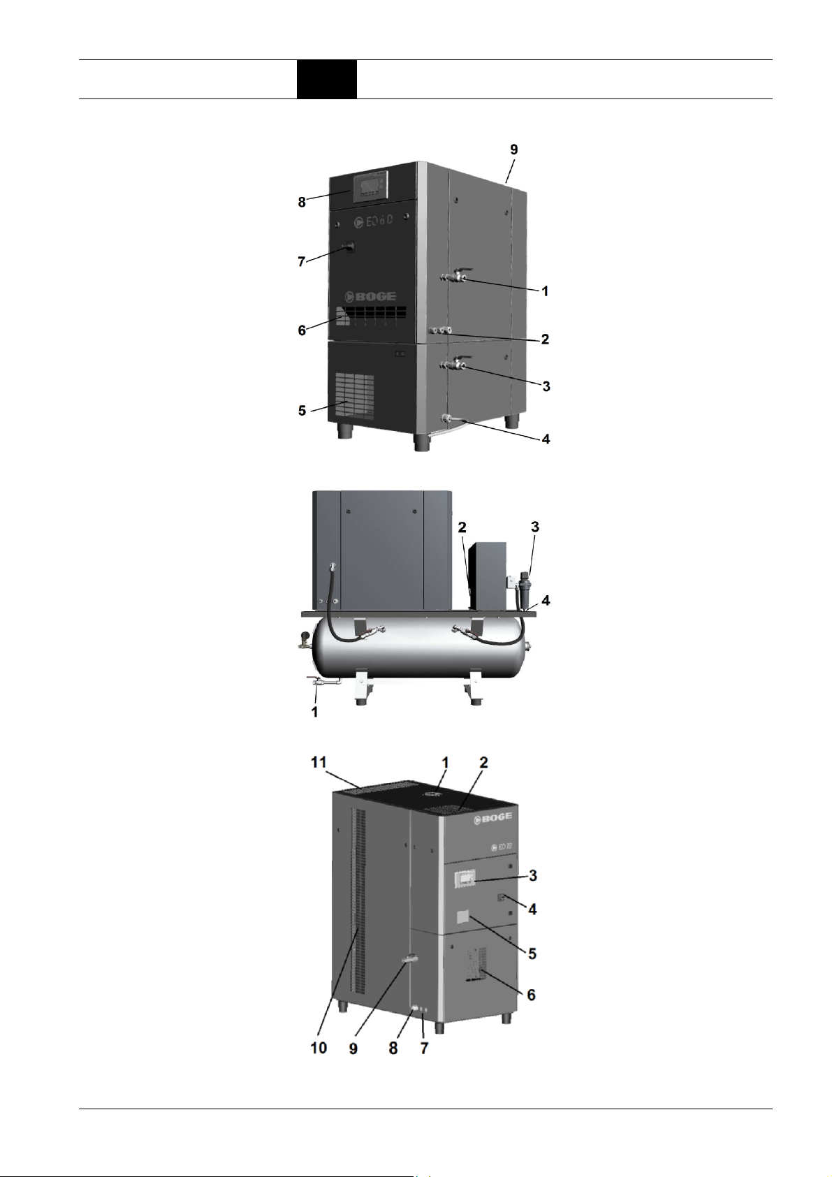
Installation 4.4 Establishing the connections
1 EO 6 G1/2“ compressed air
outlet
2 Electrical connection
3 EO 6 D G1/2“ compressed air
outlet
4 Condensate outlet (EO...D
only)
5 Supply air to dryer (EO...D
only)
6 Intake openings
7 Main switch (mains discon-
necting device)
8 Operating unit
9 Exhaust air outlet
Fig. 4.5: EO 6 D overall view
Fig. 4.6: EO 6 DR-270 rear view
1 Receiver condensate outlet
2 Dryer condensate drain (front)
3 Compressed air outlet G1/2“
4 Condensate outlet filter
1 Hood fan (EO 17...22 only)
2 Exhaust air outlet
3 Operating unit
4 Main switch (mains discon-
necting device)
5 Switch cabinet ventilation
6 Supply air to dryer (EO...D
only)
7 Condensate outlet (EO...D
only)
8 Electrical connection
9 Compressed air outlet G1"
10 Intake openings
11 Exhaust air outlet
Fig. 4.7: EO 11...EO 22 D external overall view
BOGE Operating instructions for scroll compressors, series EO 6...EO 22 D Page 39

Installation 4.4 Establishing the connections
Connecting the compressor to the compressed air network
1Establishing the electrical connection
Connect the compressed air outlet on the compressor to the compressed air
network or a compressed air receiver. Use a BOGE high-pressure hose for
this.
NOTE
Do not install a non-return valve in the pressure line.
The compressor is already equipped with a non-return valve.
DANGER
Danger of death due to electric current!
Coming into contact with live parts, defective insulation or components can
be fatal.
Ensure that all work on the electrical equipment of the compressor is only
carried out by skilled electricians.
When connecting to the mains, observe the national and international regulations in force (e.g. VDE regulations, DIN / EN standards) and the local safety
regulations.
Also observe the regulations of your local electricity utility company regarding the loading capacity of the mains.
Prior to all work:
1. Disconnect all power infeeds using the mains disconnecting device.
2. Take precautions to prevent them being switched back on again.
3. Check that all system components are de-energised.
4. Earth and short circuit.
5. Cover or enclose adjoining live parts.
Mains disconnecting device
Every compressor unit must be fitted with a mains disconnecting device in accordance with EN 60204-1. The main switch installed as standard complies
with this requirement.
Rated voltage
The data of your mains (operating voltage, control voltage, current type, frequency, etc.) must be identical to the data on the rating plate on the switch
cabinet. In the event of deviations, please contact BOGE service or your supplier.
Refer to the "Technical data" section regarding the design of the fuse protection.
Page 40 BOGE Operating instructions for scroll compressors, series EO 6...EO 22 D

Installation 4.4 Establishing the connections
Connecting the supply lines
– Check all terminals in the switch cabinet are firmly secured.
If necessary, retighten the screw connections.
– Guide the power supply cable through the threaded cable connection.
– Connect leads L1, L2, L3, N, PE (PEN) firmly to the supply terminal.
A clockwise rotating field must be created.
Retighten the electrical connections after the first 50 operating hours.
Condensate outlet connection (EO...D, EO...DR)
Scroll compressors with dryers are equipped ex works with automatic condensate drains.
NOTE
The refrigerant dryer separates water from the compressed air. Contaminants from the environment may be found in the condensate.
Î Ensure the condensate is disposed of correctly.
Î When disposing of the collected condensate, the wastewater regulations
of the local water authority must be observed. Observe water protection
regulations.
EO 6 DR, EO 17 D, EO 22 D: A minimum pressure of 2 bar is required to
ensure that the automatic condensate drain functions correctly.
ATTENTION
Risk of injury due to condensate discharge at operating pressure!
Î Install the condensate outlet in such a way that no persons or objects
can be affected by the emerging condensate.
1 from condensate drain
2 to waster water drain
The condensate drain pipe (3) should
be laid on the wall with an upward
rise of max. 5 m. This increases the
minimum operating pressure by 0.1 bar
per meter. Lay the manifold (4) min. ½"
with 1% downward gradient. Guide the
drain pipe (3) into the manifold from
above.
BOGE Operating instructions for scroll compressors, series EO 6...EO 22 D Page 41


Commissioning 5.1 Commissioning the compressor
Part 5: Commissioning 5.1 Commissioning the compressor
Checking the installation conditions
Installation location: Date of installation location inspection:
Product name:
EO 6...EO 22 D
Category Inspection parts
Installation
location
Electricity Miscellane-
Installation
area
Installation
location
Servicing Is there sufficient space for maintenance
ous
Distribution
system
Is there sufficient space to operate the
machine?
Does the installation location meet all the
criteria specified in these instructions?
Are the machine's intake air and exhaust
air outlets free?
and repair work?
Is there a stable power supply?
Are the capacity of the circuit breaker and
power cable sufficient?
Distance of the circuit breaker to the
installation location
Result
(Y)
□
□
□
□
□
□
Compressed
air
Condensate
(EO...D only)
Environment Installation
Table 5.1: Checking installations
Compressed
air outlet
Outlet Is the condensate drain pipe intact?
surface
Intake / cooling air
Are the connecting leads suitable
(operating conditions observed, compensation considered if necessary)?
Is there a shut-off device?
There are no external vibrations
Is the installation surface secure, level
and even enough for the load?
Is the ambient air free from dust?
Is the ambient air dry?
Does the intake air meet the required
conditions (temperature, quality, contaminant content)?
□
□
□
□
□
□
□
□
BOGE Operating instructions for scroll compressors, series EO 6...EO 22 D Page 43

Commissioning 5.1 Commissioning the compressor
WARNING
Risk of injury due to mechanical hazards, e.g. moving parts or sharp
edges!
The compressor should only be connected by duly authorised and experience skilled personnel.
Î Wear PPE.
Checking the pressure settings
Checking the rotation direction of the drive and fan motors
Read the supplied operating instructions for the compressor control.
Always check the respective motor's rotation direction is correct prior to initial
commissioning or after replacing the motor.
ATTENTION
Danger of property damage!
Even brief operation in the wrong rotation direction (for more than 5 seconds)
can cause significant property damage.
Î Always check the drive and fan motors' rotation direction prior to initial
commissioning.
Î Record the test result on the commissioning report.
Ensure that the rotation direction matches the arrow on the compressor stage
and the fan.
1. Close the mains disconnecting device.
2. Switch the compressor on and immediately off again to check the rotation
direction.
Changing the rotation direction
DANGER
Danger of death due to electric current!
Coming into contact with live parts, defective insulation or components can
be fatal.
Î Ensure that all work on the electrical equipment of the compressor is only
carried out by skilled electricians.
Î Open the mains disconnecting device and secure against accidental
switching on again using a padlock.
– Swap two phases (L1, L2 or L3) in the power cable.
Page 44 BOGE Operating instructions for scroll compressors, series EO 6...EO 22 D

Commissioning 5.1 Commissioning the compressor
Checking the leak
tightness of the compressed air pipes
WARNING
Risk of injury due to overpressure!
In the event of damage, malfunctioning or incorrect use, fluids under high
pressure can escape from pipes or individual components and cause severe
injuries.
Î Any work on the compressed air system must only be carried out by duly
authorised and experienced personnel.
Î Wear personal protective equipment, such as protective clothing and
protective goggles.
Î The leak tightness of the compressed air outlet connection must be
checked immediately after switching on the machine.
Î Make sure to maintain a safe distance during the inspection.
1. Close the mains disconnecting device.
2. Switch the compressor on and check the leak tightness of the compressed
air outlet.
3. Switch off the compressor.
Opening the shut-off valves
Conducting a test run
CAUTION
Risk of injury due to moving parts or sharp edges!
Î Open the mains disconnecting device and secure against accidental
switching on again using a padlock.
4. If required: have leaks repaired by experienced skilled personnel.
Record the test results.
Open the ball valve on the compressor outlet.
1. Close the mains disconnecting device.
2. Switch on the compressor using the ON button on the compressor control.
Æ The compressor starts.
Æ The compressor switches off automatically once the pre-set switch-off
pressure has been reached.
3. Check the net pressure on the control display.
4. If required, adjust the operating pressure (pressure setpoint).
Æ The compressor is ready for operation.
Æ For the control function see the control display.
5. Switch off the compressor after a several-hour test run at maximum operating load.
Record the test results.
BOGE Operating instructions for scroll compressors, series EO 6...EO 22 D Page 45

Commissioning 5.2 Shutting down / recommissioning the compressor
5.2 Shutting down / recommissioning the compressor
CAUTION
Risk of injury due to moving parts, thermal or pressure-related hazards!
Î Open the mains disconnecting device and secure against accidental
switching on again using a padlock.
Î Depressurise or block pressurised pipelines. Check that all pressurised
components are fully depressurised.
Shutting down the compressor for prolonged
periods
Recommissioning the compressor after a prolonged period of inactivity
Refrigerant compressed air dryer
1. Slacken off the V-belts.
2. Do not cover the system so that it is airtight, otherwise the corrosion of
various parts will be increased.
Compressor systems that have been switched off, inactive or in storage for
longer than three months should not be recommissioned until the measures
described below have been carried out.
To recommission the compressor after a prolonged period of inactivity proceed as follows:
1. Turn the scroll compressor manually in the rotation direction several times.
2. Tension the V-belt.
3. Connect the system: See "Commissioning the compressor" on page 43.
4. Commission the system.
NOTE
When handling used refrigerant, pay particular attention to the general safety
rules in these operating instructions.
Page 46 BOGE Operating instructions for scroll compressors, series EO 6...EO 22 D

Commissioning 5.3 Operating the DRL 6-2 DL dryer
5.3 Operating the DRL 6-2 DL dryer
The integrated DL dryer is switched on and off via the compressed air compressor.
ATTENTION
Danger of property damage!
Î Wait for approx. 5 minutes between switching the DL dryer off and on to
allow the pressure in the refrigeration system to equalise.
Condensate
After a few hours of operation with compressed air flowing, it should be
checked whether condensate is accumulating and being drained.
Pressure dew point display
The pressure dew point display
shows the pressure dew point
reached by the DL dryer.
1 Blue field: pressure dew point too low
2 Green field: pressure dew point OK
3 Red field: pressure dew point too high
Fig. 5.1: Pressure dew point display
BOGE Operating instructions for scroll compressors, series EO 6...EO 22 D Page 47


Servicing and maintenance 6.1
Basic information on servicing
Part 6: Servicing and maintenance
Servicing safety information
6.1 Basic information on servicing
Your compressor has an integrated monitoring system in the form of the compressor control, which informs you in good time about the most important maintenance work via a maintenance warning.
The basic servicing intervals for the compressor are set by BOGE Service personnel via the control during commissioning depending on the ambient conditions.
This enables the most important maintenance work to be performed regularly
and, over the long-term, to keep compressor wear to a minimum and to guarantee the machine has a long service life.
You should also observe the information in the supplied operating instructions
for accessories and optional equipment.
WARNING
Risk of injury due to mechanical hazards, e.g. moving parts or sharp
edges!
WARNING
Hot surfaces.
Risk of burns from thermal hazards!
WARNING
Pressurised components.
Risk of injury due to overpressure!
CAUTION
Risk of injury due to contact with hazardous substances, e.g. from
inhalation!
BOGE Operating instructions for scroll compressors, series EO 6...EO 22 D Page 49

Servicing and maintenance 6.1
In all circumstances:
Ensure that maintenance work is only carried out by duly authorised and
qualified personnel or appropriately trained personnel.
Î Wear personal protective equipment.
Î Prior to starting any maintenance work, always stop the compressor as
described in these operating instructions before removing any cladding
or safety devices. Refit the cladding or safety devices immediately upon
completion of the maintenance work.
Î Heavy components may only be lifted by multiple persons in accordance
with the local industrial safety regulations.
Î Only use original spare parts and operating materials approved by BOGE
for the maintenance and service work.
Î When the automatic restart (Auto-Restart) is activated, the compressor
will start automatically following a power failure. Prerequisite: the net
pressure is lower than the set switch-on pressure.
Basic information on servicing
Page 50 BOGE Operating instructions for scroll compressors, series EO 6...EO 22 D

Servicing and maintenance 6.1
DANGER
Danger of death due to electric current!
Coming into contact with live parts, defective insulation or components can
be fatal.
Ensure that all work on the electrical equipment of the compressor is only
carried out by authorised skilled electricians.
Always adhere to the procedure described below for all maintenance work.
Never omit a single safety step. Otherwise, you will risk injuries due to restarting, electric shock or self-releasing parts.
Prior to all maintenance work:
1. Switch off the compressor using the OFF button.
2. Open the mains disconnecting device and secure against accidental
switching on again using a padlock.
3. After switching off the power supply, wait until the fan comes to a stop
and all indicator lights go out.
4. Fix a warning sign to the control and fill in the name of the person who
is authorised to switch the machine back on.
5. Check that all system components are definitely de-energised.
6. Allow all hot compressor components to cool to 50°C before starting any
work.
7. Disconnect the compressor from the compressed air network. To do so,
close the ball valve on the compressed air outlet.
8. Depressurise the compressor completely. One possible method is to
vent the safety valves on the scroll units:
– Turn the knurled nut anti-clockwise until you feel resistance from
– Turn the knurled nut a little more. Any residual air escapes.
– Once all the residual air has escaped from the system, retighten
9. Remove all the safety claddings necessary for maintenance work.
Basic information on servicing
the spring.
the knurled nut.
After the maintenance work has been completed:
10. Refit all removed safety claddings.
11. Open the ball valve on the compressed air outlet.
12. Prior to switching on again, ensure that nobody else is still working on
the compressor.
13. Only then may the warning sign be removed and the mains disconnecting device switched back on again.
BOGE Operating instructions for scroll compressors, series EO 6...EO 22 D Page 51

Servicing and maintenance 6.1
Basic information on servicing
Servicing by BOGE customer service recommended
Servicing overviews
Arrange for BOGE Service to fully check and service your compressor after
every 3,000 operating hours or annually.
NOTE
Maintenance contract.
Enter into a maintenance contract with BOGE.
BOGE Service will carry out the proper maintenance on your compressor at
regular intervals. As well as adhering to the warranty claim conditions, this
guarantees maximum safety and reliability of your compressed air supply.
Overview with internal view of machine (EO 6 D)
Fig. 6.1: Maintenance work on EO 6, EO 6 D
1 Check main switch (mains disconnecting device) / emergency stop func-
tion
2 Check / replace suction filter
3 Clean the secondary cooler
4 EO 6 D: check function of condensate drain
5 EO 6 D: cyclone separator servicing
6 EO 6 D: DRL 6-2 refrigerant dryer servicing
7 Cooling air fan on scroll unit
8 Clean primary cooler (rear of compressor)
Page 52 BOGE Operating instructions for scroll compressors, series EO 6...EO 22 D

Servicing and maintenance 6.1
Additional maintenance work for compressed air systems and compressor stations
Overview of machine (EO 6 DR)
Basic information on servicing
Fig. 6.2: Overview of additional maintenance work on the compressor unit or
station
1 Check receiver safety valve for proper functioning
2 Drain condensate from receiver
3 EO 6 DR: DS dryer servicing incl. condensate drain and cyclone sepa-
rator
4 EO 6 DR: filter servicing
BOGE Operating instructions for scroll compressors, series EO 6...EO 22 D Page 53

Servicing and maintenance 6.1
Overview with internal view of machine (EO 11)
Fig. 6.3: Maintenance work on EO 11...16
1 Clean the secondary cooler
2 Check / replace suction filter
3 Clean the primary cooler
4 Cooling air fan on scroll unit
5 Check main switch (mains disconnecting device) / emergency stop function
6 Check / replace supply air filter for switch cabinet ventilation
Basic information on servicing
Overview with internal view of machine (EO 22 D)
Fig. 6.4: Maintenance work on EO 17...22 D
1 Clean the secondary cooler
2 Check / replace suction filter
3 Clean the primary cooler
4 Cooling air fan on scroll unit
5 EO...D: DS refrigerant dryer servicing
6 EO...D: check function of condensate drain
7 EO...D: cyclone separator servicing
8 Check / replace supply air filter for switch cabinet ventilation
9 Check main switch (mains disconnecting device) / emergency stop function
Page 54 BOGE Operating instructions for scroll compressors, series EO 6...EO 22 D

Servicing and maintenance 6.1
Overview of scroll unit
Fig. 6.5: Maintenance work on scroll unit EO 6 (left) and EO 11...22
1 Tension / replace the V-belt
2 Drive motor: bearing with permanent lubrication
3 Check / replace suction filter
4 Check / replace pressure hose
5 Check / replace non-return valve
6 Clean cooling air outlet
7 Clean cooling air fan on scroll unit
8 Check safety valve for proper functioning
Basic information on servicing
BOGE Operating instructions for scroll compressors, series EO 6...EO 22 D Page 55

Servicing and maintenance 6.1
Basic information on servicing
Maintenance Intervals
The servicing intervals specified in the following tables are based on average
operating and ambient conditions.
Extreme conditions may require shorter servicing intervals.
The first table contains servicing and maintenance work to be carried out by
the customer at regular intervals in between the annual BOGE Service maintenance work.
BOGE recommends having the servicing and maintenance work listed in the
second table performed by BOGE Service to ensure the warranty claim conditions are adhered to.
NOTE
Note down all maintenance work in the table on the final pages. This will
facilitate troubleshooting for BOGE Service.
Maintenance work between fixed servicing intervals
The following servicing and maintenance work must be carried out by authorised and qualified personnel and will ensure your compressor functions flawlessly between fixed servicing intervals.
Maintenance work Page
Weekly:
Check compressor / air system for leaks –
Check final compression temperature (max. 250°C) Control
Monthly:
Check / clean suction filter on scroll compressor 60
Check main switch (mains disconnecting device) / emergency stop function
Control panel /
control
Check operating pressure, adjust if necessary Control
For EO 11...22 D only: Check supply air filter for switch cabinet, replace if necessary 60
Check screw connections on the compressor are tightened properly –
Every 1,500 operating hours
1)
(or six-monthly):
Check that electrical connections have been tightened properly –
Clean the coolers (primary and secondary coolers) 61
Every 3,000 operating hours
1)
(or annually):
Replace suction filter 60
Every 5,000 operating hours
1)
(or every 2 years):
Clean cooling air fan on scroll compressor (10 bar) 63
Every 10,000 operating hours
1)
(or every 4 years):
Clean cooling air fan on scroll compressor (8 bar) 63
1)
If the compressor is not used frequently, servicing must be carried out after the specified interval regardless of the number of operating hours.
Table 6.1: Maintenance work between servicing intervals
Page 56 BOGE Operating instructions for scroll compressors, series EO 6...EO 22 D

Servicing and maintenance 6.1
Basic information on servicing
Maintenance work at fixed servicing intervals
To ensure the warranty claim conditions are adhered to, BOGE recommends
having the following servicing and maintenance work carried out by certified
BOGE Service personnel using original spare parts.
ATTENTION
Compressor damage caused by improper servicing!
The compressor may be damaged or destroyed if maintenance work is
omitted or carried out incorrectly.
Î Have the following maintenance work carried out by authorised BOGE
Service personnel only.
Î Only use original spare parts.
Maintenance work (BOGE Service personnel) Page
1)
Every 3,000 operating hours
(or annually):
Check safety valve(s) for proper functioning 65
Check compressor for leaks –
Check V-belts 66
Check non-return valves 66
Every 5,000 operating hours
1)
(or every 2 years):
Replace "Tip Seal" sealant on scroll compressor (10 bar) 66
Service / lubricate scroll compressor bearing (10 bar) 66
Clean cooling fins on scroll compressor (10 bar) 66
Every 10,000 operating hours
1)
(or every 4 years):
Replace "Tip Seal" sealant on scroll compressor (8 bar) 66
Service / lubricate scroll compressor bearing (8 bar) 66
Clean cooling fins on scroll compressor (8 bar) 66
Replacing the V-belt 66
Replace non-return valves –
Every 15,000 operating hours
1)
(or every 6 years):
Replace scroll compressor (10 bar) 68
Every 20,000 operating hours
1)
(or every 8 years):
Replace scroll compressor (8 bar) 68
Special servicing intervals:
Lubricate drive motor bearing 68
1)
If the compressor is not used frequently, servicing must be carried out after the specified interval regardless of the number of operating hours.
Table 6.2: Maintenance work at fixed servicing intervals carried out by BOGE Service personnel
BOGE Operating instructions for scroll compressors, series EO 6...EO 22 D Page 57

Servicing and maintenance 6.1
Basic information on servicing
Maintenance work on the dryer (EO...D)
EO 6 DR, EO 17 D, EO 22 D: Also observe the instructions supplied with the
DS refrigerant dryer.
EO 6 D, EO 11 D: See "Maintenance work on the DRL DL dryer 6-2" on
page 68.
Maintenance work
Daily:
For DRL 6-2 only: check pressure dew point
Weekly:
Check condensate outlet
Every 4 months:
For DS only: clean condenser fins
Check power consumption
Annually:
Condensate drain servicing*
Cyclone separator servicing*
For DS filter servicing only*: replace filter elements, check float drain
General information on lubricants and refrigerants
* Follow the supplied operating instructions.
Table 6.3: Maintenance work on the dryer
CAUTION
Risk of injury due to contact with hazardous substances!
Lubricants and refrigerants can pose a potential danger to health and the
environment.
Î Avoid contact with skin and eyes. Always wear protective gloves made
of resistant plastic.
Î Observe the information on the relevant safety data sheets.
Page 58 BOGE Operating instructions for scroll compressors, series EO 6...EO 22 D

Servicing and maintenance 6.1
Basic information on servicing
Disposing of used operating materials and condensates
Pressure hoses
EO...D only: the air taken in contains water in the form of vapour, which turns
into condensate during compression.
ATTENTION
Danger of environmental damage!
Hazardous substances, e.g. lubricants and cleaning agents, must be handled and disposed of in accordance with legal provisions.
Î Ensure these substances are disposed of correctly.
Î When disposing of the collected condensate, the wastewater regulations
of the local water authority must be adhered to. Observe the water protection law.
WARNING
Possible sudden discharge of fluid.
Risk of injury from material failure if unsuitable pressure hoses are
used!
Unsuitable, e.g. old pressure hoses, cannot withstand the operating loads
and may burst, causing serious injuries.
Î Do not re-use pressure hoses.
Î Defective or leaking pressure hoses must never be repaired; they must
always be replaced immediately.
Î Do not use pressure hoses beyond their permissible service life. The
manufacturing date is printed on the hose. BOGE recommends replacing pressure hoses after a usage period of max. five years (including
storage time).
Î Replace pressure hoses with original spare parts approved by BOGE
only.
Spare and wearing parts
CAUTION
Risk of injury when using unsuitable materials and components, e.g.
as a result of mechanical failure!
Danger of property damage!
Only use original spare parts and operating materials approved by BOGE
during repair or maintenance work.
Î BOGE accepts no liability for damage caused by the use of other spare
parts and operating materials.
BOGE Operating instructions for scroll compressors, series EO 6...EO 22 D Page 59

Servicing and maintenance 6.2
6.2 Performing maintenance work between fixed servicing intervals
Performing maintenance work between fixed servicing intervals
Monthly: Check / replace supply air filter for switch cabinet ventilation
Type EO 11...EO 22 D only.
Check the function of the supply air filter mats in the switch cabinet:
– Once per month, however at least every 500 operating hours.
– Reduce interval if the air taken in is heavily polluted.
Replace the supply air filter mats:
– When dirt becomes encrusted on the filter mats, or at least once a year.
NOTE
Always keep a sufficient stock filter mats as replacements.
Replacing the supply air filter mat on the switch cabinet
1. Switch off the compressor using the OFF button.
DANGER
Danger of death due to electric current!
Coming into contact with live parts, defective insulation or components can
be fatal.
Prior to all work on the switch cabinet:
Î Open the mains disconnecting device and secure against accidental
switching on again using a padlock.
Monthly: checking / cleaning the suction filter
2. Remove the cladding, see Figure 6.1.
3. Take the filter out of the cartridge.
4. Fit the new filter.
5. Re-fit the cladding.
Clean:
– Once per month, however at least every 500 operating hours.
– Reduce interval if the air taken in is heavily polluted.
Change:
– If damaged.
– After it has been cleaned twice.
Page 60 BOGE Operating instructions for scroll compressors, series EO 6...EO 22 D

Servicing and maintenance 6.2
1. Switch off the compressor using the OFF button.
CAUTION
Risk of injury due to sharp edges and exposure to dust!
This maintenance work should only be carried out by authorised and qualified personnel.
Î Wear PPE.
Prior to the maintenance work:
2. Open the mains disconnecting device and secure against accidental
switching on again using a padlock.
Removing the filter cartridge
3. Open the compressor housing at the front.
4. Remove the filter housing lid (1).
5. Take out the filter cartridge (2).
Cleaning the filter cartridge
Performing maintenance work between fixed servicing intervals
Every 1,500 operating hours: Cleaning the cooler
ATTENTION
Danger of property damage!
Do not clean the filter cartridge in liquids.
Î Do not use hard objects for cleaning as doing so will damage the filter
paper.
Replace the filter cartridge if it is damaged or has been cleaned twice.
6. Tap the filter cartridge with your hand to knock out coarse dust.
7. Blow out fine dust using dry compressed air (maximum pressure 5 bar)
from the inside to the outside.
8. Clean the sealing surfaces of the filter cartridge.
Fitting the filter cartridge
9. Insert the filter cartridge into the filter case.
10. Attach the lid of the filter case.
Clean:
– After 1,500 operating hours but no less than every six months.
NOTE
The service life of the primary and secondary coolers depends on the degree
of soiling in the intake cooling air. Heavy external soiling of the coolers leads
to an excessively high temperature in the air system.
BOGE Operating instructions for scroll compressors, series EO 6...EO 22 D Page 61

Servicing and maintenance 6.2
1. Switch off the compressor using the OFF button..
WARNING
Risk of injury due to sharp edges, hot surfaces and exposure to dust!
This maintenance work should only be carried out by authorised and qualified personnel.
Î Wear PPE.
Prior to the maintenance work:
2. Open the mains disconnecting device and secure it to prevent it being
switched on again.
3. Allow all hot compressor components to cool to 50°C.
Performing maintenance work between fixed servicing intervals
Fig. 6.6: Clean Type EO 6...EO 6 TR secondary cooler
Fig. 6.7: Clean Type EO 11...EO 22 secondary cooler
Page 62 BOGE Operating instructions for scroll compressors, series EO 6...EO 22 D

Servicing and maintenance 6.2
4. Remove all the safety claddings necessary for maintenance work.
5. Open the respective housing panel. Secondary cooler: remove the housing panel above the operating elements / control.
ATTENTION
Danger of property damage!
Î Do not use sharp objects to clean the cooler. They may damage the
cooler.
6. Clean off the accumulated soiling with a fibre brush.
7. Primary cooler: suck out any dirt from the system in the same direction
as the normal flow of cooling air. Do not under any circumstances blow
the dirt into the system using compressed air.
Secondary cooler: blow out any dirt with compressed air (1) in the opposite direction to the normal flow of cooling air (see fig. 6.6 and 6.7).
8. Suck up the blown out dirt using an industrial vacuum cleaner (2) (see fig.
6.6 and 6.7).
After the maintenance work has been completed:
9. Secondary cooler: screw the side panels back onto the airflow box.
10. Refit all removed safety claddings and housing panels.
11. Prior to switching on again, ensure that nobody else is still working on the
compressor.
12. Only then may the warning sign be removed and the mains disconnecting
device switched back on again.
Performing maintenance work between fixed servicing intervals
Every 5,000 or 10,000 operating hours: Cleaning the fan
NOTE
If a cooler is very heavily soiled (cleaning with compressed air is no longer
possible), it must be dismantled and cleaned by BOGE customer service.
Clean the cooling air fan on the scroll unit:
– After 5,000 operating hours (or 2 years) for a 10-bar machine or 10,000
operating hours (or 4 years) for an 8-bar machine.
NOTE
The service life of the fans depends on the degree of soiling in the intake
cooling air.
BOGE Operating instructions for scroll compressors, series EO 6...EO 22 D Page 63

Servicing and maintenance 6.2
Fig. 6.8: View of the right side of the EO 6 (left) and EO 11...22 scroll unit housing
1 Fan cover
2 V-belt
3 Protective equipment
Performing maintenance work between fixed servicing intervals
1. Switch off the compressor using the OFF button.
WARNING
Risk of injury due to sharp edges, hot surfaces, overpressure and
exposure to dust!
This maintenance work should only be carried out by authorised and qualified personnel.
Î Wear PPE.
Prior to the maintenance work:
2. Open the mains disconnecting device and secure it to prevent it being
switched on again.
3. Allow all hot compressor components to cool to 50°C.
4. Depressurise the system.
5. Remove the right side panel of the housing and the isolating protective
equipment (3).
6. Remove the V-belts (2).
7. Loosen the screws on the scroll compressor fan covers (1) and remove
the covers.
8. Check the fans and clean if necessary.
After the maintenance work has been completed:
9. Refit all removed safety claddings, covers and housing panels.
10. Prior to switching on again, ensure that nobody else is still working on the
compressor.
11. Only then may the warning sign be removed and the mains disconnecting
device switched back on again.
Page 64 BOGE Operating instructions for scroll compressors, series EO 6...EO 22 D

Servicing and maintenance 6.3
6.3 Having maintenance work performed at fixed servicing intervals
Having maintenance work performed at fixed servicing intervals
Every 3,000 operating hours: Changing the suction filter cartridge
Change the suction filter cartridge:
– If damaged.
– After it has been cleaned twice.
– Depending on soiling, also after 3,000 operating hours or annually at serv-
icing intervals.
Changing the filter cartridge
1. Switch off the compressor using the OFF button.
WARNING
Risk of injury due to sharp edges, hot surfaces, overpressure and
exposure to dust!
This maintenance work should only be carried out by authorised and qualified personnel.
Î Wear PPE.
Prior to the maintenance work:
2. Open the mains disconnecting device and secure it to prevent it being
switched on again.
3. Allow all hot compressor components to cool to 50°C.
4. Depressurise the system.
Every 3,000 operating hours / annually: Function check of the safety valves
5. Remove the old filter cartridge (see “Removing the filter cartridge” on
page 61).
6. Insert the new filter cartridge (see “Fitting the filter cartridge” on page 61).
WARNING
Risk of injury from flying parts caused by overpressure, e.g. pressurised components bursting or detonating!
Risk of injury due to sudden discharge of hot compressed air!
It is forbidden to operate the compressor without the installed safety devices.
A safety valve prevents inadmissible overpressure.
Î The specified final compression pressure must not be exceeded.
Î Observe the statutory regulations applicable in the installation location
for operating safety devices against overpressure.
BOGE Operating instructions for scroll compressors, series EO 6...EO 22 D Page 65

Servicing and maintenance 6.3
Have the function of the safety valve checked exclusively by BOGE Service
personnel.
Interval: After approx. 3,000 operating hours but at least once a year.
Having maintenance work performed at fixed servicing intervals
Every 3,000 operating hours / annually: Checking the V-belts
Every 3,000 operating hours / annually: Checking the non-return valves
Every 5,000 / 10,000 operating hours: Scroll compressor servicing
Every 10,000 operating hours: Replacing the V-belts
Check the V-belts:
– After approx. 3,000 operating hours but at least once a year for damage,
correct tension and alignment.
Check the function of the non-return valves on the scroll units:
– After 3,000 operating hours but at least once a year.
10 bar compressor: After 5,000 operating hours but after two years at the
latest. 8 bar compressor: After 10,000 operating hours but after four years at
the latest.
Have the following maintenance work on the scroll compressors carried out
exclusively by BOGE Service personnel.
The following work must be carried out:
– Replace "Tip Seal" sealant on scroll compressor
– Service / lubricate scroll compressor bearing
– Clean cooling fins on scroll compressor
Replace the V-belts:
– If visibly damaged.
– After 10,000 operating hours.
Replacing the V-belts:
1. Switch off the compressor using the OFF button.
WARNING
Risk of injury due to sharp edges, hot surfaces, overpressure and
exposure to dust!
This maintenance work should only be carried out by authorised and qualified personnel.
Î Wear PPE.
Prior to the maintenance work:
2. Open the mains disconnecting device and secure it to prevent it being
switched on again.
3. Allow all hot compressor components to cool to 50°C.
4. Depressurise the system.
5. Remove the service side cladding.
Page 66 BOGE Operating instructions for scroll compressors, series EO 6...EO 22 D

Servicing and maintenance 6.3
6. Remove the belt protection.
To slacken off the V-belts:
Fig. 6.9: Replacing the EO 6...EO 6 TR V-belts
Having maintenance work performed at fixed servicing intervals
7. Loosen all four motor fastening screws (2).
8. Turn the belt tensioning
screw (1) anti-clockwise.
9. Move the motor in the
direction of the arrow until
the V-belts are fully slackened.
7. Loosen all four motor fastening screws (2).
8. Turn the belt tensioning
screw (1) anti-clockwise.
9. Move the motor in the
direction of the arrow until
the V-belts are fully slackened.
Fig. 6.10: Replacing the EO 11...EO 22 D
10. Remove the relieved V-belt from the pulley.
11. Position the new V-belt on the pulley on the motor and compressor.
To tension the new V-belts:
12. Turn the belt tensioning screw (1) clockwise until the belt is correctly
tensioned.
NOTE
The new V-belts must be exactly the same length. Always replace the V-belts
as an entire set.
The belt tension is correct when the belts can be pressed in approx. 8 – 9 mm
in the middle between the two pulleys with a weight of 2.5 kg.
13. Reattach the motor fastening screws.
14. Fit the belt protection.
15. Refit the service side cladding.
BOGE Operating instructions for scroll compressors, series EO 6...EO 22 D Page 67

Servicing and maintenance 6.4
Special maintenance work
Every 15,000 / 20,000 operating hours: Replacing the scroll compressor
Drive motors with permanent lubrication
Heavily loaded scroll compressors should be replaced once a specific service
life has expired.
Intervals:
10 bar compressor: after 15,000 operating hours but after six years at the
latest.
8 bar compressor: After 20,000 operating hours but after eight years at the
latest.
Have the scroll compressor replaced exclusively by BOGE Service personnel.
6.4 Special maintenance work
The bearings of the drive motors used have maintenance-free permanent
lubrication.
Under normal operating conditions (ambient temperature max. 40°C, continuous operation) the bearings are maintenance-free within their service lives.
Higher or lower thermal loads (due to a higher or lower ambient temperature)
can change the service life of the bearings.
Daily checks
Weekly maintenance
Annual maintenance
6.5 Maintenance work on the DRL DL dryer 6-2
ATTENTION
Risk of injury from incorrectly performed work!
Î Observe all the safety rules for electrical systems and equipment before
commencing any maintenance work (see chapter “General safety information” on page 7).
NOTE
As the servicing intervals depend heavily on the respective operating and
installation conditions, only approximate values can be given here.
Monitor the pressure dew point.
Check and if necessary clean the condensate drainage system.
Condensate drain: replace the set of wearing parts.
For more information, please refer to the separate operating instructions for
the condensate drain.
Page 68 BOGE Operating instructions for scroll compressors, series EO 6...EO 22 D

Servicing and maintenance 6.6
ATTENTION
Danger from overpressure!
Risk of injury due to the sudden discharge of fluids.
Î Maintenance work may only be carried out on the condensate drain when
it is in a depressurised state.
6.6 Disposal after dismantling or replacement of
parts
DANGER
Danger of death due to electric current!
Coming into contact with live parts, defective insulation or components can
be fatal.
Work on the electrical equipment of the compressor may only be carried out
by an authorised and qualified electrician.
Prior to all work on the switch cabinet:
Î Open the mains disconnecting device and secure against accidental
switching on again using a padlock.
Disposal after dismantling or replacement of parts
WARNING
Risk of injury due to sharp edges, hot surfaces, overpressure and
hazardous substances!
Î Dismantling of the compressor should only be carried out by duly author-
ised and qualified personnel.
Î Also note all information on safe dismantling of the refrigerant dryer and
safe disposal of the refrigerant in the supplied operating instructions for
the Type DS dryer and in the safety data sheet for the refrigerant.
NOTE
Dispose of all system parts in such a way that health and environmental
damage is avoided.
Should you have any questions about this product, please contact
Technical Support on:
Telephone: +49 5206 601-140
BOGE Operating instructions for scroll compressors, series EO 6...EO 22 D Page 69

Servicing and maintenance 6.7
The following electronic components must always be disposed of separately:
– Displays, display devices
– Electrical power supply
– Controls
– Circuit boards with electronic components
Hazardous substances such as refrigerant and lubricants, as well as contaminated components if applicable, must be disposed of separately.
6.7 Spare parts and additional equipment
Spare parts and additional equipment
List of spare and wearing parts (for maintenance)
Spare parts for the DRL 6-2 DL dryer
Spare parts for the DS dryer
Name
Suction filter cartridge
Supply air filter mat on the switch cabinet
Compressor service kit incl. grease
V-belts
NOTE!
The spare parts inventory is continuously updated by BOGE. Should you
require spare parts for the integrated DRL 6-2 compressed air dryer, please
contact BOGE Technical Support:
Telephone: +49 5206 601-140
A list of available spare parts can be found in the separate operating instructions for the DS dryer.
List of available
Name
additional equipment
Additional equipment for treating compressed air
Automatic condensate drain
Attention!
Please always specify the following information on the type plate when
ordering:
– Type
– Year of manufacture
– Machine number
Page 70 BOGE Operating instructions for scroll compressors, series EO 6...EO 22 D
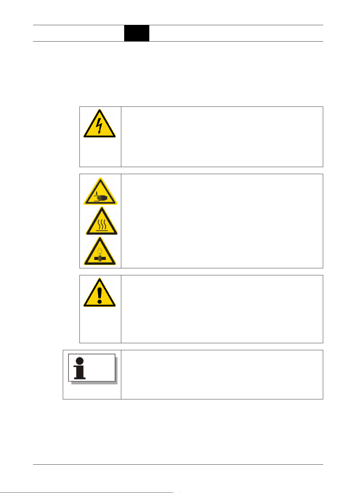
Remedying faults 7.1 Basic information on remedying faults
Part 7: Remedying faults
7.1 Basic information on remedying faults
The tables on the following pages give information on the possible causes of
operating faults and measures for their rectification (please also refer to the
operating instructions for the compressor control).
DANGER
Danger of death due to electric current!
Coming into contact with live parts, defective insulation or components can
be fatal.
Prior to any work required to remedy faults:
Î Open the mains disconnecting device and secure against accidental
switching on again using a padlock.
WARNING
Risk of injury due to mechanical hazards, e.g. moving parts, hot surfaces or overpressure!
Î Ensure that any work required to remedy faults is only carried out by
trained personnel or specialists.
Î Ensure that components which have a safety function are only set,
repaired or exchanged by BOGE Service personnel.
CAUTION
Risk of compressor damage!
If fault and problem rectification (incl. maintenance and repair work) is carried
out by unauthorised or unqualified personnel, this can damage or destroy
the compressor.
Î Faults and problems may only be rectified by authorised and skilled
personnel or BOGE Service personnel.
Î If in doubt, contact BOGE Service.
Should you have any questions about this product,
please contact Technical Support on:
Telephone: +49 5206 601-140
If you require Service assistance, please contact BOGE Service on:
Telephone: +49 5206 601-100
BOGE Operating instructions for scroll compressors, series EO 6...EO 22 D Page 71

Remedying faults 7.1 Basic information on remedying faults
Compressor faults
Fault Possible cause Rectification
No or low free air
delivery, no pressure
build-up
Compressor system
does not start
Safety valve blows off Operating pressure setpoint has
System components in the
compressor are leaking
Scroll compressor seals are
worn out
Suction filter soiled Clean suction filter
Torn V-belt Install new V-belt(s)
No power to compressor Check electrical connection
Fuses are faulty Check mains and control fuses and replace if necessary
Power fluctuations in the electrical supply network
changed
The information provided in the following table refers to the compressor system or an individual scroll unit. Depending on the machine type, several scroll
units may be installed.
Check the compressed air pipes inside the compressor;
retighten or reseal the screw connections if necessary
Replace seals
Ensure there is constant voltage in accordance with IEC 38
Set the operating pressure to the maximum permitted pressure
of the scroll compressor
Safety valve is faulty Replace safety valve
Control switches off as
temperature too high
Running unsteady V-belt tension incorrect Check belt tension
Table 7.1: List of possible faults
Critical ambient conditions Check installation conditions
Incorrect operating parameters
set
Cooler / fan operation faulty Check cooler and fan functions, clean or replace components if
Sensor system faulty Check sensor system, replace if necessary
V-belts are not the same length Replace with an identical belt set
Loose screw connections on
drive side
Change settings on the control
necessary
Check screw connections
Page 72 BOGE Operating instructions for scroll compressors, series EO 6...EO 22 D

Remedying faults 7.1 Basic information on remedying faults
Refrigerant dryer and treatment faults (EO...D)
fault Possible cause Rectification
Function Power supply is faulty – Check the power supply.
Water in compressed air
network
DRL 6-2 DL dryer
switches off during
operation
Faulty condensate drain
(blocked drain pipe,
minimum operating pressure
not reached)
DL dryer is being switched off
by the installed electrical
start-up and protective equipment due to overload
Condenser is dirty Clean the condenser.
Observe the information in the supplied operating instructions for the Type DS
dryer, condensate drain and cyclone separator.
– If the power supply is OK, contact BOGE Service or send the
DL dryer to the manufacturer.
Clean condensate drain with a neutral cleaning agent
– Rectify the cause of the fault.
– The DL dryer will switch back on automatically once the pro-
tective equipment has cooled down.
Note: the device may not switch back on immediately,
as the protective equipment needs a certain amount of time
to cool down to an acceptable operating temperature.
High pressure difference
on the compressed air
side
Features:
– Pressure difference on
the compressed air side
is increasing.
– Volume flow is decreas-
ing.
Table 7.2: List of possible faults on the dryer
DL dryer is freezing Switch off the device and continue to allow compressed air to flow.
After approx. After approx. 1/2 h, the pressure difference will return
to the normal value.
Switch the device back on. If the device freezes again, contact
BOGE Service.
BOGE Operating instructions for scroll compressors, series EO 6...EO 22 D Page 73


Appendix 8.1 Guidelines and standards
Part 8: Appendix 8.1 Guidelines and standards
The compressor conforms to the following guidelines and standards:
Guidelines and directives
– Machinery Directive 2006/42/EC
– EMC Directive 2014/30/EU
In addition, the compressor complies with the protection objectives in the
following directives:
– Pressure Equipment Directive 2014/68/EU
– Simple Pressure Vessels Directive 2014/29/EU
– Low Voltage Directive 2014/35/EU
Applied harmonised standards
– EN 1012-1
– EN ISO 12100
– EN 60204-1
– EN 61000-6-2
– EN 61000-6-4
Scope
8.2 Application of the Pressure Equipment Directive
This section covers the application of the Pressure Equipment Directive (PED)
to the specified compressor series and their pressurised components.
List of machines (8 and 10 bar max. operating pressure for each type):
–EO 6
–EO 6 D
–EO 6 R
–EO 6 DR
–EO 6 TR
–EO 11
– EO 11 D
– EO 16
–EO 17
– EO 17 D
–EO 22
– EO 22 D
BOGE Operating instructions for scroll compressors, series EO 6...EO 22 D Page 75

Appendix 8.3 Pneumatic circuit diagrams
Classification and
assessment of pressurised components
Compressor / compressed air systems and compressor stations are assemblies according to the PED. The classification of an assembly according to the
PED is based on the highest category of the individual components.
Compressor components
Pipelines
(compressed air pipe
system, cooler, hoses)
Safety equipment *
(safety valves)
Compressed air receiver Ps * V > 3000
Compressor / compressor
block
Optional equipment
(e.g. filter, dryer,
condensate drain,
cyclone separator)
Pressure volume
product Ps*V
Pressure nominal width
product Ps*DN
Ps * DN < 1000 Art. 4, 3 PED
n.a.
n.a.
misc. Art. 4, 3 PED
Classification / assessment according to PED
Category IV according to
Art. 2,4 (not taken into
consideration for assembly
assessment according to
Art. 14)
Excluded from scope
according to Art. 1, 2.c
Excluded from scope
according to Art. 1, 2.j
Conformity assessment
procedure to be applied
according to directive...
PED
Simple Pressure Vessels
Directive
Machinery Directive
Outcome of the assessment
Installation in compressed air systems
Every aspect of the assembly of the pressurised compressor components
mentioned above is excluded from the scope of the Pressure Equipment
Directive (PED).
Justification: According to Art. 1, 2.f of the PED, assemblies which in their
entirety would fall into Category 1 at the highest are excluded from the scope
of the PED if they are covered by the Machinery Directive.
The installation of the assemblies mentioned above in a compressed air system does not constitute a new assembly in the sense of the PED, provided
that the integrated components are excluded from the scope of the PED.
8.3 Pneumatic circuit diagrams
The following pages contain the individual pneumatic circuit diagrams for the
different machine types.
Page 76 BOGE Operating instructions for scroll compressors, series EO 6...EO 22 D

Appendix 8.3 Pneumatic circuit diagrams
Pneumatic circuit diagram for EO 6, air-cooled
101 Intake air INLET
102 Compressed air OUTLET
1 Intake air temperature *
2 Suction filter
3Unit
4 Final compression temperature
5Safety valve
6 Non-return valve
7 Primary cooler
8 Secondary cooler
9 Net pressure
10 Ball valve (option)
11 Cyclone separator (option)
12 Condensate drain (option)
* with focus control 2.0
BOGE Operating instructions for scroll compressors, series EO 6...EO 22 D Page 77

Appendix 8.3 Pneumatic circuit diagrams
Pneumatic circuit diagram for EO 6 D, air-cooled
101 Intake air INLET
102 Compressed air OUTLET
1 Intake air temperature *
2 Suction filter
3Unit
4 Final compression temperature
5 Safety valve
6 Non-return valve
7 Primary cooler
8 Secondary cooler
9 Net pressure
10 Cyclone separator
11 Refrigerant dryer
12 Condensate drain
13 Ball valve
14 Hose
* with focus control 2.0
Page 78 BOGE Operating instructions for scroll compressors, series EO 6...EO 22 D

Appendix 8.3 Pneumatic circuit diagrams
Pneumatic circuit diagram for EO 6 R, air-cooled
101 Intake air INLET
102 Compressed air OUTLET
1 Intake air temperature *
2 Suction filter
3Unit
4 Final compression temperature
5Safety valve
6 Non-return valve
7 Primary cooler
8 Secondary cooler
9 Net pressure
10 Ball valve
11 Receiver
12 Pressure indicator
13 Receiver safety valve
14 Condensate drain
15 Hose
16 Receiver condensate drain (option)
* with focus control 2.0
BOGE Operating instructions for scroll compressors, series EO 6...EO 22 D Page 79

Appendix 8.3 Pneumatic circuit diagrams
Pneumatic circuit diagram for EO 6 DR, air-cooled
101 Intake air INLET
102 Compressed air OUTLET
1 Intake air temperature *
2 Suction filter
3Unit
4 Final compression temperature
5 Safety valve
6 Non-return valve
7 Primary cooler
8 Secondary cooler
9 Net pressure
10 Ball valve
11 Receiver
12 Pressure indicator
13 Receiver safety valve
14 Dryer
15 Bypass line
16 Filter (option)
17 Receiver condensate drain (option)
18 Hose
* with focus control 2.0
Page 80 BOGE Operating instructions for scroll compressors, series EO 6...EO 22 D

Appendix 8.3 Pneumatic circuit diagrams
Pneumatic circuit diagram for EO 6 TR, air-cooled
101 Intake air INLET
102 Compressed air OUTLET
1 Intake air temperature *
2 Suction filter
3Unit
4 Final compression temperature
5Safety valve
6 Non-return valve
7 Primary cooler
8 Secondary cooler
9 Net pressure
10 Ball valve
11 Receiver
12 Pressure indicator
13 Receiver safety valve
14 Receiver condensate drain (option)
15 Hose
* with focus control 2.0
BOGE Operating instructions for scroll compressors, series EO 6...EO 22 D Page 81

Appendix 8.3 Pneumatic circuit diagrams
Pneumatic circuit diagram for EO 11 (D), air-cooled
101 Intake air INLET
102 Compressed air OUTLET
1 Intake air temperature
2 Suction filter
3 Scroll unit 1, 2
4 Final compression temperature
5 Safety valve
6 Non-return valve
7 Compressed air primary cooler
8 Compressed air secondary cooler
9 Net pressure
10 Cyclone separator (EO 17 D)
11 Refrigerant dryer (EO 17 D)
12 Condensate drain (EO 17 D)
13 Compressed air outlet temperature
14 Shut-off valve compressed air outlet
Page 82 BOGE Operating instructions for scroll compressors, series EO 6...EO 22 D

Appendix 8.3 Pneumatic circuit diagrams
Pneumatic circuit diagram for EO 16, air-cooled
101 Intake air INLET
102 Compressed air OUTLET
1 Intake air temperature
2 Suction filter
3 Scroll unit 1,2,3
4 Final compression temperature
5Safety valve
6 Non-return valve
7 Compressed air primary cooler
8 Compressed air secondary cooler
9 Net pressure
10 Compressed air outlet temperature
11 Shut-off valve compressed air outlet
BOGE Operating instructions for scroll compressors, series EO 6...EO 22 D Page 83

Appendix 8.3 Pneumatic circuit diagrams
Pneumatic circuit diagram for EO 17 (D), air-cooled
101 Intake air INLET
102 Compressed air OUTLET
1 Intake air temperature
2 Suction filter
3 Scroll unit 1,2,3
4 Final compression temperature
5 Safety valve
6 Non-return valve
7 Compressed air primary cooler
8 Compressed air secondary cooler
9 Net pressure
10 Cyclone separator (EO 17 D)
11 Refrigerant dryer (EO 17 D)
12 Condensate drain (EO 17 D)
13 Compressed air outlet temperature
14 Shut-off valve compressed air outlet
Page 84 BOGE Operating instructions for scroll compressors, series EO 6...EO 22 D

Appendix 8.3 Pneumatic circuit diagrams
Pneumatic circuit diagram for EO 22 (D), air-cooled
101 Intake air INLET
102 Compressed air OUTLET
1 Intake air temperature
2 Suction filter
3 Scroll unit 1,2,3,4
4 Final compression temperature
5Safety valve
6 Non-return valve
7 Compressed air primary cooler
8 Compressed air secondary cooler
9 Net pressure
10 Cyclone separator (EO 17 D)
11 Refrigerant dryer (EO 17 D)
12 Condensate drain (EO 17 D)
13 Compressed air outlet temperature
14 Shut-off valve compressed air outlet
BOGE Operating instructions for scroll compressors, series EO 6...EO 22 D Page 85

Appendix 8.4 List of maintenance work performed
8.4 List of maintenance work performed
Servicing of the
refrigerant dryer,
cyclone separator
condensate drain,
scroll unit
Servicing of the
Function check
of safety valves
Please record the maintenance work you have completed in the relevant column
Check / clean
Check / set net /
Check / clean /
Check final
Check / replace
cooler
operating
replace
compression
supply air filter
pressure
suction filter
temperature
ventilation
for switch cabinet
hours
Operating
Date
Page 86 BOGE Operating instructions for scroll compressors, series EO 6...EO 22 D


 Loading...