


M-line
GB
M2(W) / M3(W) / M6W
Operator’s Manual
0404-02-01-14 V15

M2(W) / M3(W) / M6W
1
CONTENTS
SUBJECT
Page
OVERVIEW ……………………………………..
2
TECHNICAL SPECIFICATIONS ……………………………………..
3
STANDARD EQUIPMENT ……………………………………..
4
OPTIONAL EQUIPMENT ……………………………………..
4
MAINTENANCE AND CARE
Normal maintenance………………….. 5
Special maintenance……………………. 6
Lubrication………………………………. 7
Generally…………………………………. 7
Spreading vanes…………………………. 7
……………………………………..
5
GUARANTEE / RESPONSIBILITY ……………………………………..
8
GENERALLY ……………………………………..
8
SAFETY and PROTECTION AGAINST ACCIDENT ……………………………………..
8
SPREADING SYSTEM ……………………………………..
9
SETTING SYSTEM ……………………………………..
10
FUNCTION – How to do ……………………………………..
11
MACHINE SETTINGS / Normal and late application
PTO- speed…………………………… 13
TILT ANGLE…………………………….. 14
HEIGHT,
incl. late application….... 14
SETTING OF QUANTITY……………….. 16
VANE / SPREAD WIDHT…………….. 17
FUNCTION SPREADING VANE…….. 18
Trend SYSTEM…………………………… 19
……………………………………..
13
NORMAL spreading
Practical test………………………………. 21
Test with test trays……………………… 22
Examples of NORMAL spread patterns... 24
…………………………………..…
21
HEADLAND spreading TO BORDER
Practical test………………………………. 28
Test with test trays……………………… 28
Ex. of HEADLAND spread patterns….. 29
……………………………………..
26
HEADLAND spreading FROM BORDER
Ex. of HEADLAND spread patterns.. 31
……………………………………..
30
REDUCED SPREAD WIDTH …………………………………..…
32
TURNING AT THE HEADLANDS …………………………………..…
33
SPREADING ON NON-RECTANGULAR FIELDS ……………………………………..
34
CHECK THE TRACTOR – before use ……………………………………..
35
CHECK THE SPREADER – before use ……………………………………..
35
PRACTICAL HINTS ……………………………………..
36
M2W/M3W – special ……………………………………..
37
USE OF CALIBRATION RATE CHECK KIT
REST EMPTYING……………………….. 38
……………………………………..
38
EC-Declaration of Conformity ……………………………………..
43
PICTOGRAM ……………………………………..
44
NOTES ……………………………………..
45
NB ! Fitting instruction for different options – are supplied with the options.
M2(W) / M3(W) / M6W
2
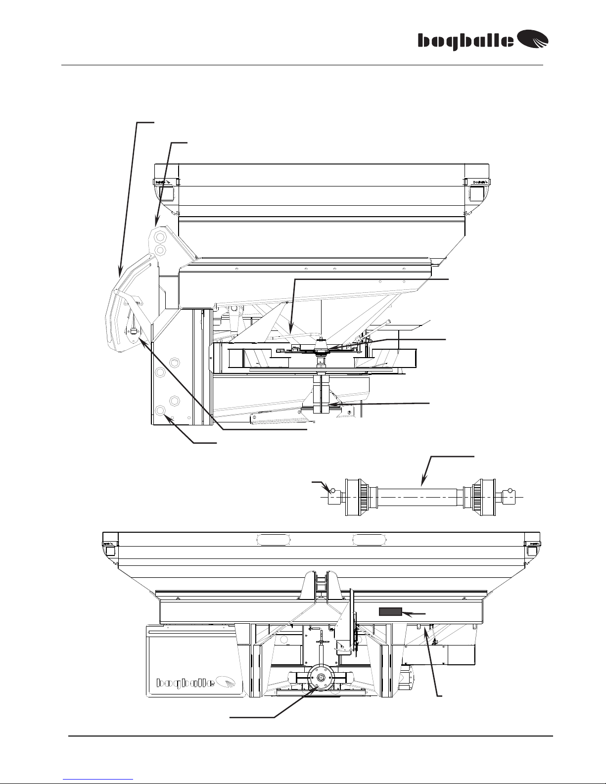
OVERVIEW – M3 illustration
F) Setting pointer
Degree meter
Top link fixture
J) Link pins
I) Angle transmission
G) Connection rod
D
)
Shutter
A) Cardan joint
B) Telescope
Serial No. plate
E) Setting axle

M2(W) / M3(W) / M6W
3
TECHNICAL SPECIFICATIONS, general
•
M2(W) Hopper volume :
base
1.250 – 2.350
Litres
•
M2(W) Hopper volume :
plus
1.800 – 3.000
Litres
•
M3(W) Hopper capacity :
plus
1.800 – 4.050
Litres
•
M6W Hopper capacity :
plus
4.050 – 5.550
Litres
•
M2(W) Hopper capacity :
base
Max. 2.500
Kg.
•
M2(W) Hopper capacity :
plus
Max. 3.000
Kg.
•
M3(W) Hopper capacity :
plus
Max. 4.000
Kg.
•
M6W Hopper capacity :
Plus
Max. 6.000
Kg.
•
Spread width :
12 – 42
Metres
•
Spreading capacity :
Ca. 0,35 – 400
Kg/min.
•
3-point linkage :
M2/M3
M6W
Cat. II / ISO 730/I
Cat. III / ISO730/I
TECHNICAL SPECIFICATIONS, specific
The volume of the M2/M2W base machine can be increased in steps of 550 litres by
mounting modules (max. 2 modules).
The volume of the M2/M2W plus machine can be increased in steps of respectively 450
litres and/or 750 litres by mounting modules.
The volume of the M3/M3W and M6W plus machine can be increased in steps of 750 litres
by mounting modules (M3/M3W max. 3 modules – M6W max. 5 modules).
SPECIFICATION M2base
1.250
M2
base
1.800
M2base
2.350
M2
plus
1.800
M2plus
2.550
M2
plus
3.000
M3plus
1.800
M3
plus
2.550
M3plus
3.300
M3
plus
4.050
M6Wplus
5.550
Load height
cm. 102 120 140 110 130 141 110 130 148 167 204
Hopper volume
Litres 1250 1800 2350 1800 2550 3000 1800 2550 3300 4050 5.550
Hopper capacity
Kg. 1375 1980 2500 1980 2500 3000 1980 2.800 3630 4000 6.000
Hopper width
cm. 240 240 240 290 290 290 290 290 290 290 290
Hopper depth
cm. 125 125 125 140 140 140 140 140 140 140 140
Fill opening
cm.
234 x 116 234 x 116 234 x 116 284 x 131284 x 131 284 x 131284 x 131 284 x 131 284 x 131 284 x 131
284 x 131
Outside b x l
cm.
240 x 137 240 x 137 240 x 137 290 x 144290 x 144 290 x 144290 x 164 290 x 164 290 x 164 290 x 164
290 x 164
Outside “W”
cm.
240 x 137 240 x 137 240 x 137 290 x 144290 x 144 290 x 144290 x 172 290 x 172 290 x 172 290 x 172
290 x 172
Net weight
Kg. 406 435 464 450 492 518 510 552 594 636
Net weight “W”
Kg. 490 519 548 534 576 602 660 702 744 786 1.044
Total weight
Kg. 1496 2125 2754 2430 2992 3518 2490 3352 4224 4636
Total weight “W”
Kg. 1580 2209 2838 2514 3076 3602 2640 3502 4374 4786 7.044
The hopper capacity is made from hopper volume in litres multiplied with a specific weight of 1,1 Kg/litres.
NB! Max. hopper capacity: M2(W)base : 2.500 Kg
M2(W)plus : 3.000 Kg
M3(W)plus : 4.000 Kg
M6W plus : 6.000 Kg

M2(W) / M3(W) / M6W
4
STANDARD EQUIPMENT
The M() / M()W machine is from factory supplied with all necessary standard equipment.
• PTO shaft with free wheeling
• Headland spreading TO BORDER, Trend with manually reversible transmission.
• Agitators, Excentric free- and slow rotating.
• Screens to open, 2 units with cones.
• Closing of only one outlet, choose right or left.
• Reduction outlet for micro granules, without use of tools.
• System for late application, link pins can be mounted in 2 heights.
• Degree meter, for setting the tilt angle of the machine.
• Transmission, with reversible gear and friction clutch / overload coupling.
• Mud guards
• TREND shift
(only M2W, M3W and M6W)
• Traffic Lights
OPTIONAL EQUIPMENT
The following options can be supplied for the machine:
COMPONENT DESCRIPTION DIMENSION ART. NO.
Module, base
M2(W) 550 litres
240 x 125
cm
6920-01
Module, plus
M2(W) 450 litres
290 x 140
cm
6930-17
Module, plus
M() / M()W 750 litres
290 x 140
cm
6930-10
Hydraulic control M(), Incl. tube with valve
6381-01
Cable control M(), Only between 0 and 250 Kg/min.
6380-01
CALIBRATOR ZURF M(), Electric operating system
6386-01
TREND kit, FROM BORDER M() / M()W, fixtures FROM BORDER 6395-10
BORDER-kit,
Manual, DOUBLE SHIFT
M() / M()W, Fittings
TO and FROM BORDER
6395-20
TREND, SHIFT M2 / M3, Electric shift
6390-30
TREND, DOUBLE SHIFT M() / M()W, Electric shift
6395-40+30
Cable kit, HEADLAND spreading M(), Operation from drivers seat 280
cm
4690-28
do. M(), Operation from drivers seat 380
cm
4690-38
do. M(), Operation from drivers seat 480
cm
4690-48
Hydraulic motor M() / M()W, Incl. tubes and valves
6932-50
Hopper cover, base M2(W), Foldable w/full opening 240 x 125
cm
6921-45
Hopper cover, plus M() / M()W, Foldable w/full opening 290 x 140
cm
6931-45
Transport wheels M() / M()W, 4 Ø110 mm plastic wheels
6930-50
Connection system M(), +40% / -40%
6381-23
do. M()W, +40% / -40%
6381-29
Ladder
M2 / M2W
6932-70
Ladder Extension
M() / M()W, only with M-Trail
6932-85
Set of screens f/wide tyres
M2/ M2W
6930-90
M2-Trail M2(W), Chassis Kit
1800-55
M3-Trail M3(W), Chassis Kit
1830-03
Trend Vanes, complete M() / M()W, System E1-T (L/R) 12 – 18
metres
4650-12
do. M() / M()W, System E2-T (L/R) 20 – 24
metres
4650-20
do. M() / M()W, System E6-T (L/R) 28 – 36
metres
4650-28
do. M() / M()W, System E8-T (L/R) – 42
metres
4650-36
do. M() / M()W, System U1-T (L/R) 12 – 18
metres
4650-50
All BOGBALLE products are subject to a continuous development. Therefore the list might not always be up-to-date.
M2(W) / M3(W) / M6W
5
MAINTENANCE AND CARE
NORMAL MAINTENANCE
The BOGBALLE machine is manufactured in such a way that it requires a minimum
of maintenance.
In the construction it is considered that cleaning and lubrication can be completed
quickly and thoroughly – without taking apart the machine.
The surface treatment consists of a robust powder paint – in addition all essential
wear parts and bolt assemblings are made of stainless steel.
Many of the components of the machine are greased once and need no extra
maintenance, for instance the central and angle gears of the transmission.
The maintenance mentioned below is absolutely necessary!
”If the machine is maintained – it will still be new - in 5 years!”
”If the machine is not maintained – it will be old – next year!”
The machine must always be thoroughly cleaned after use. The cleaning
should be done with water perhaps with soap in it. When using a highpressure cleaner only use low pressure and do not clean direct on the axle
seals of the transmission.
Do not use grease-removing cleaning liquid – without giving the
machine – just after drying – an application of anti corrosion oil.
It is strongly recommended to grease the machine - BEFORE using it
first time. Remember always to grease all of the machine in a
corrosion protecting liquid (for instance oil). It is not sufficient just to wash
the machine.
• Without protection, rust might arise within a few hours in
areas, where the paint has been damaged – because fertiliser
salts hold acid and is therefore most corrosive.
Any paint damage should be cleaned and painted. A possibility could also be to treat
the damage by Tectyl or a similar product.
Please consider that cleaning products and corrosion protecting
liquids might include dissolvents that might dissolve the glue fixing the
transfers.
M2(W) / M3(W) / M6W
6
SPECIAL MAINTENANCE, Friction clutch
The transmission of the machine is equipped with friction/overload
clutch.
The friction clutch is a most important component protecting against
overload – and a damaged transmission / PTO- shaft.
The friction clutch protects especially the reversible gear system
of the Trend transmission. The Trend-system is based on an
inpact clutch.
The friction clutch must be maintained, and it must be checked,
that it is not corroded.
The friction clutch must ”slip” at START of the tractor PTO.
If the clutch does not slip – the transmission will be damaged.
The friction clutch ”slips” approx. 1-2 turns at START of the tractor PTO. This reduces
the load on the components of the transmission to approx. 1/10 of the load to which the
transmission is exposed, if the coupling is not able to ”slip”.
As principal rule the coupling must be separated and cleaned if
the machine has not been used for more than 6 months.
Alternatively minimum once a year.
It is always necessary to START the tractor PTO
”slowly / smoothly”!
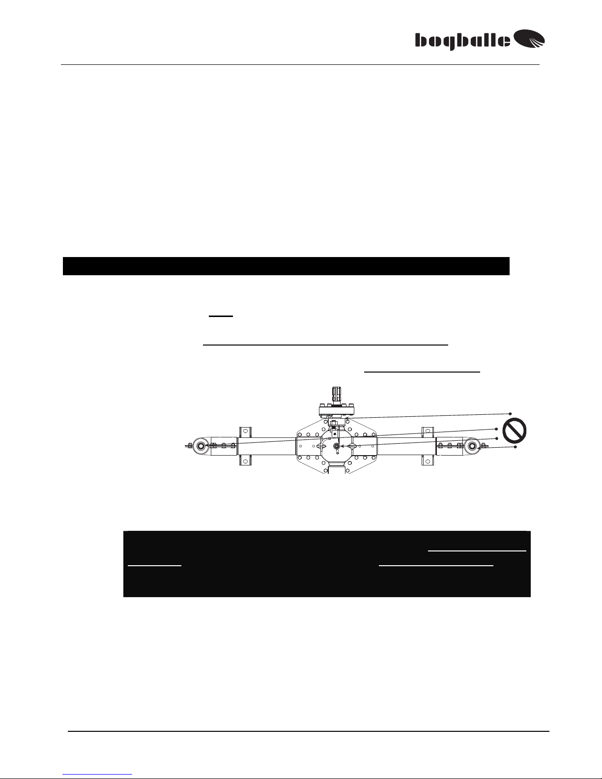
GUIDANCE ON HOW TO CLEAN THE FRICTION CLUTCH.
Demount the 6 bolts of the clutch – and the clutch is
separated.
Clean all the ”slip sur-
faces” for rust (perhaps
with a wire brush) – and
reassemble the bolts.
If needed replace the
clutch plates.
The clutch surfaces should not
be greased with oil/grease!
The friction clutch’s bolts are tightened by a torque wrench:
The splined axle has to slip at:
60 N/m
180 – 220 N/m
2 coupling plates
BOLTS
Splined axle

M2(W) / M3(W) / M6W
7
LUBRICATION
The components below must be greased according to below instruction.
See the explaining sketch in the paragraph ”OVERVIEW”.
LUBRICATION ONCE A DAY:
POS. COMPONENT INSTRUCTION
A
B
C
D
E
F
G
Cardan joint and lock of the PTO
Telescope axles of the PTO
Agitator R and L
(Under cone)
Setting and closing shutter (Bottom of hopper)
Adjustment axle (Cross axle w/ 4 bearings)
Setting handle
(Axle w/ 2 bearings)
Connection rods (Rods between axle and shutters)
Use grease
Use grease
Use grease
Use oil
Use oil
Use oil
Use oil
Note
C)
If the agitators are overgreased, a high pressure might restrict the rotation of the
agitator bearing. If this is the case the lubricator nipple must be demounted, which
will release the pressure. Grease sparingly – e.g. one pump/season.
PARTS GREASED ONCE:
The central and angle gears are filled with special grease and needs
no lubrication.
GENERAL
A new machine will always ”move” a little bit in all nuts +bolts.
Therefore all nuts and bolts of the machine must be retightened
- first time it is put into operation - after 5 to 8 hours’ operation.
Exception is the bolts in the central and angle gears – these are
locked with lock-tite.
Be aware that stainless nuts + bolts might ”weld together” When
mounting such bolts – the thread must be greased with cutting
lubricant or copper grease !
SPREADING VANES
The spreading vanes are manufactured of high quality manganese
steel, MN12.
(MN 12 has a hardness corresponding to 3 times the hardness of
stainless steel)
.
But still the vanes will be worn due to modern and abrasive fertilisers.
Therefore the vanes must be considered a wear part – that must be
exchanged dependent on the quantity / type of fertiliser.
Always clean contact surfaces of the vanes and the spreading
disc for dust etc – before mounting and tightening the vane !
IF HOLES ARE WORN IN THE VANES THEY MUST BE
EXCHANGED AT ONCE!

M2(W) / M3(W) / M6W
8
GUARANTEE / RESPONSIBILITY
• Claim conditions are according to Danish legislation. Service and repair are
made free of cost within 12 months from date of purchase on the following
conditions:
• That the failure is due to construction or material faults
(Normal wear, missing maintenance and misuse not included).
• That the failure is not due to not original components / equipments.
• That persons with no technical knowledge to the machine have not tried to repair.
• Compensation for person or crop injury do not fall on the supplier.
GENERALLY
This machine is intended for spreading all common types of fertiliser.
Spreading of other flowing materials might also be possible. If so we draw the
attention to data list of the material concerned in order to determine possible safety
or health measures to be taken.
If the machine is used for spreading material which is not defined in the spread
charts for the spreader, the manufacturer of the machine can never be held
responsible.
SAFETY and PROTECTION
The transmission system of the machine:
PTO shaft, friction clutch and spreading discs w/vanes – must be considered”as
dangerous”, and absolute care must be taken with these machine parts, especially
in connection with rotation of the tractor PTO system.
DO NOT LEAVE THE TRACTOR CABIN – WITHOUT STOPPING THE PTO
SYSTEM OF THE TRACTOR!
Except when you have to calibrate the machine.
• Never go behind the machine – with rotating spreading discs.
• Never go under the machine – with rotating spreading discs.
• Never clean the machine - with rotating spreading discs.
• Never put hand/object into the hopper – with rotating spreading discs.
• Always check that the spreading vanes are correctly fixed.
• Check that the protection tubes of the PTO are intact.
• Check that the security chain of the PTO is fixed.
• Check that top link and top link pins are intact and secured by lynch pin.
• Check that lift arms and link pins are secured by lynch pin.

M2(W) / M3(W) / M6W
9
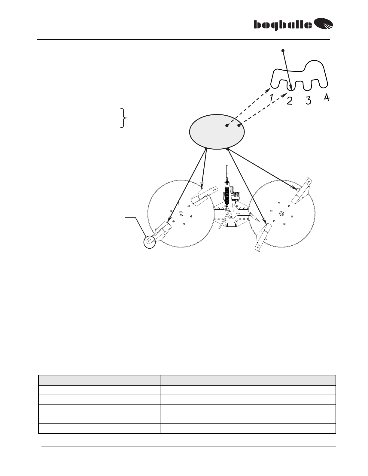
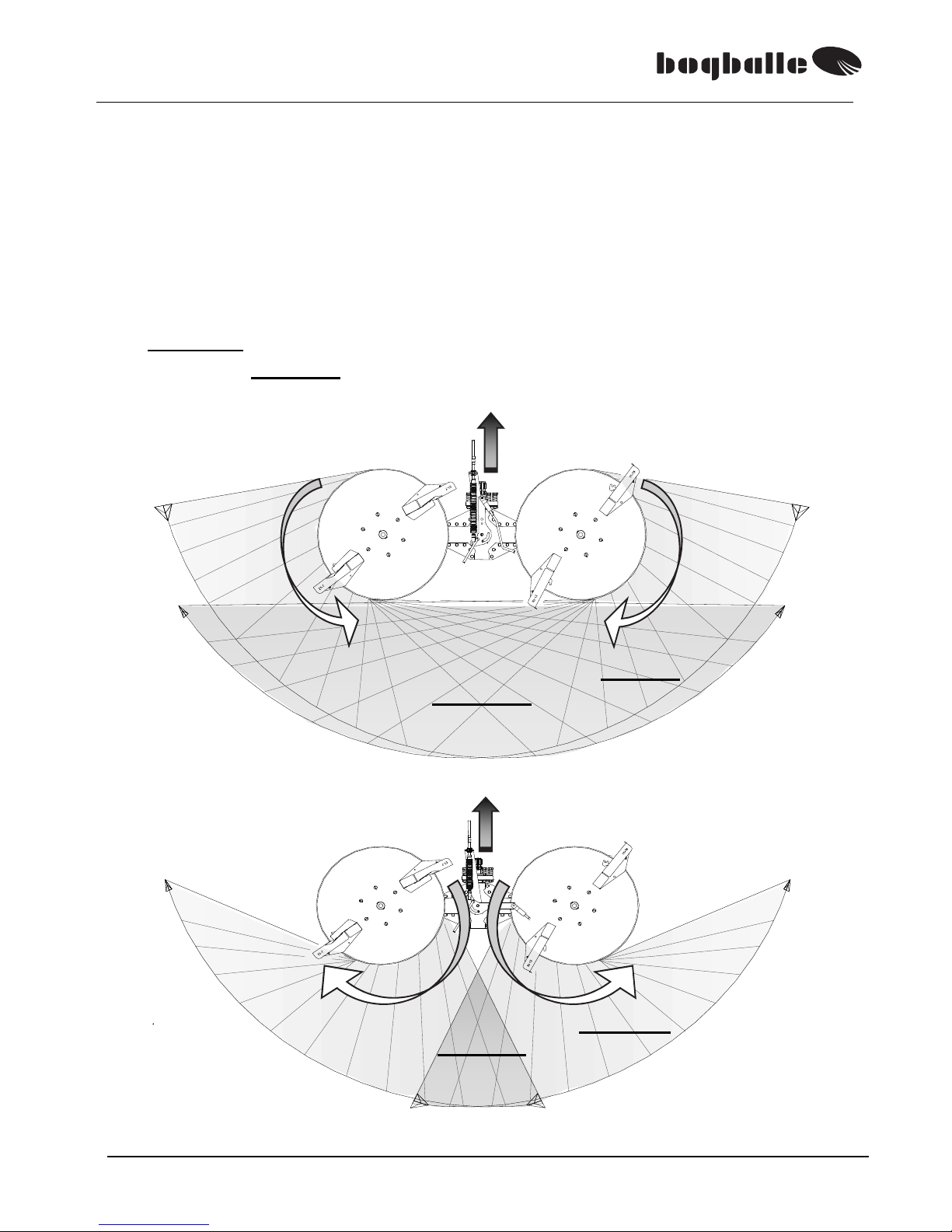
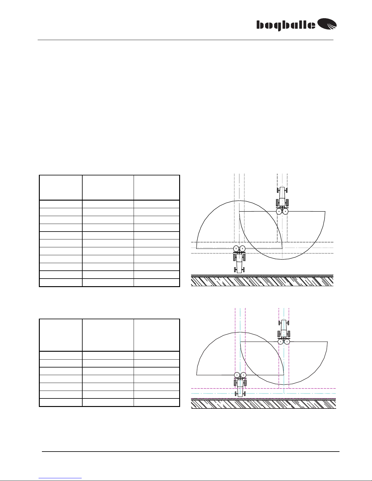
SPREADING SYSTEM
The BOGBALLE spreading system is base on an Integrated Center System – ICS,
where the spreading discs of the machine during NORMAL spreading – rotate
against each other – and spread in an angle on 180°, with full overlap.
The spreading system can with optimum fertilisers manage full overlap, on spread
width up to 28 metres.
This means in practice that right and left spreading disc form two opposite spread
patterns – overlapping each other.
Each spreading disc spreads the full spreading width. That means that the fertiliser
from the two spreading discs A and B – overlap each other. The spread width is
with good fertilisers - twice as wide as the distance between the tramlines - up to
28 metres.
This way you achieve a 4-double overlap – which ensures a most even distribution
of the fertiliser.
As shown in the diagram the spreading is made from the
present tramline – to the middle of the next two tramlines.
The spreading system is developed in such a way that
you are able to spread the fertiliser with a minimum of
machine setting.
This means in practice that you get a uniform distribution – no matter
which type of fertiliser and without special settings.
The BOGBALLE machine is therefore only equipped with one setting
handle – for setting the quantity.
+=
M2(W) / M3(W) / M6W
10
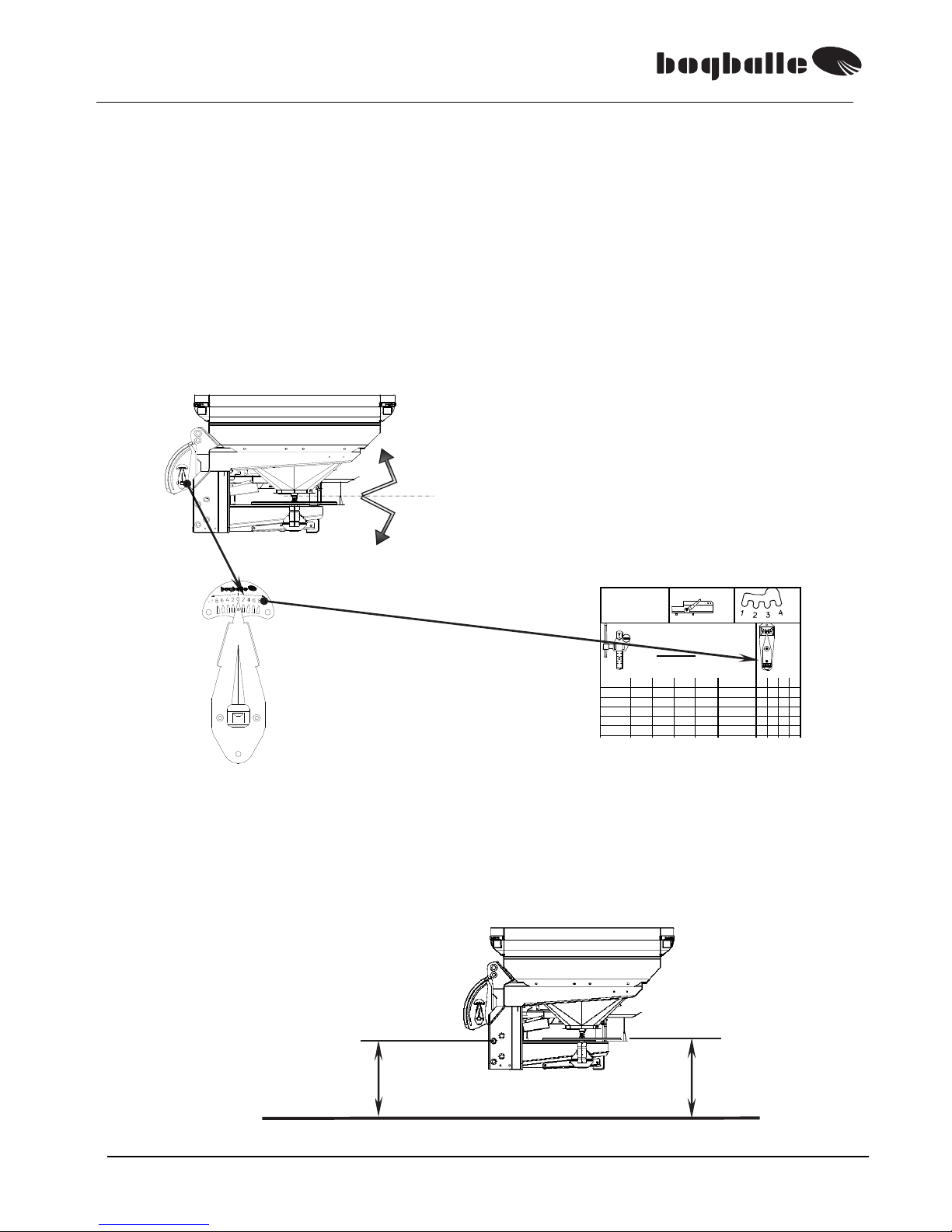
SETTING SYSTEM
The setting system consists of a scale pointer, different connection rods and
outlet shutters.
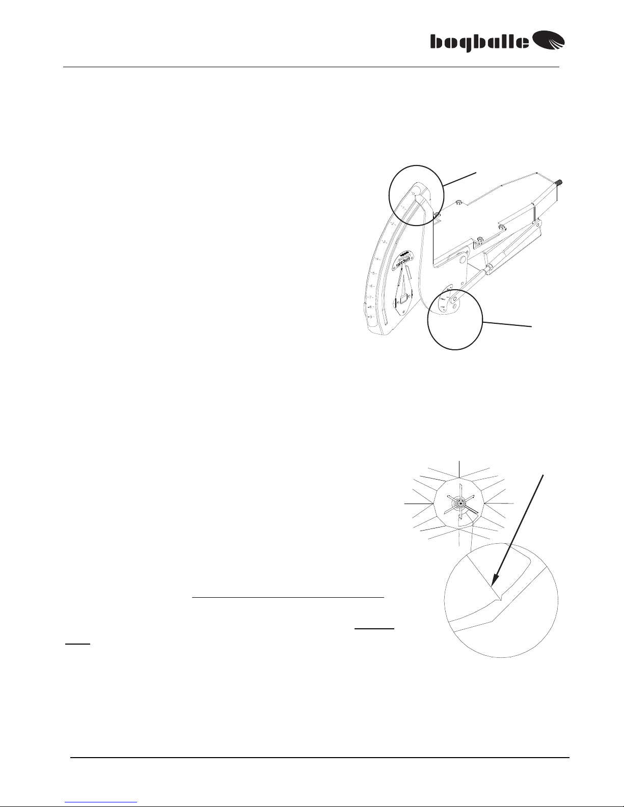
SETTING POINTER,
Hydraulic / CALIBRATOR.
➊& ➋
The connection rod of the setting pointer must
be mounted / adjusted in such a way, that the
shutters of the spreader are closed - when the
setting pointer is placed on the scale ciffer ”0”.
(approx. 0,5 mm. opening)
The adjustment is made on the connection rod.
➌
As standard the connection rod is mounted in position
(Ø10 mm.)
In case very large quantities being used on 28 - 42 metres' spread width, a +40% /
-40% connection rod
(Ø12 mm.) can be used as option.
Same connection rod is used for very small quantities (Ø8 mm.).
ADJUSTMENT SHUTTERS
The shutters in the adjustment system are factory set so
that the machine distributes the fertiliser symmetrically.
That means that the fertiliser is shared in equal quantities
to each side of the machine.
The adjustment shutters must be adjusted so that the
shutters close exactly in the middle of the V-mark of
the bottom plate.
Normally you should not adjust the 4 connection rods
connecting the adjustment axle of the machine and the
shutters of the machine. These connection rods should
only be adjusted in case the system has been
dismantled and therefore misadjusted.
The setting is of great importance for the symmetry of the spread pattern.
Be aware that the adjustment shutters do not open equally in comparison to the Vmark. This assymmetric function ensures automatic adjustment of the feed point
for precise spreading.
➊
➌
➋

M2(W) / M3(W) / M6W
11
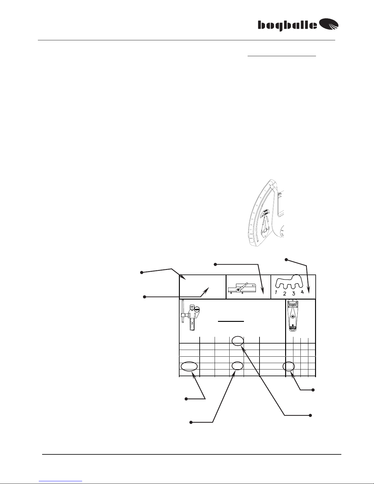
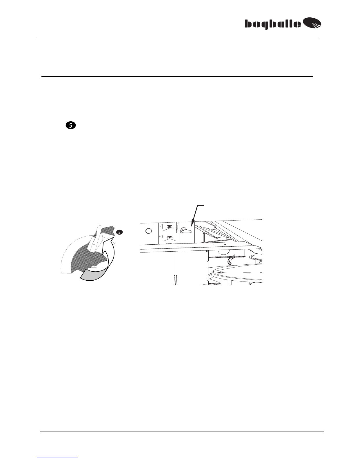
OUTLET SHUTTERS
The machine’s hopper bottom is equipped with a turnable outlet shutter for right
and left side respectively.
The outlet shutter can be locked in three different positions.
0 Closed outlet
(Calibration / rest emptying)
1 Normal outlet
(For fertiliser)
2 Reduced outlet (For micro granules)
”2” .is only used if stated in the contents page of the spread chart.
The outlet shutters are set by pressing the handle
(A) against the hopper – and at the same time turn
the outlet shutter to the required position. The
handle locks the shutter in the U- cut.
FUNCTION
• The Trend sytem gives distribution of fertiliser a totally new dimension, where
PRECISION, USER FRIENDLINESS and RELIABILITY, are the three main
areas in which BOGBALLE M() / M()W – differs most essentially from the other
products in the market.
• The Trend system is the only transmission in the market with
reversible rotation direction.
The reversible rotation direction gives the optimum result for use of the
rotation direction, … towards the centre is most suitable for spreading on
the main area on the field, NORMAL spreading – and the reverse rotation
direction is most suitable for HEADLAND spreading at field borders.
…..high PRECISION is achieved, no matter which type of
spreading !
2
0
1
A
U- cut

M2(W) / M3(W) / M6W
12
• The Trend system ensures an optimum result, with a minimum of setting.
• The transmission of the machine with reversible rotation direction
together with the double function of the spreading vane ensure that the
spreader can be transformed from NORMAL spreading to HEADLAND
speading – by making only one change.
• The full 180° overlap is the key reason for achieving an optimum
NORMAL spread pattern – without other setting of the machine.
Therefore neither the length or the angle of the vane must be adjusted.
Also no side adjustmnet is necessary.
• The feed point of the machine is automatically shifted in comparison to
the quantity of fertiliser spread. This means that the feed point need
not be set.
…..high USER FRIENDLINESS is achieved, no matter which spreading!
• The design of the machine ensures maximum flexibility – without
making compromises.
• The slow rotating agitators of the machine prevents ”crushing” of the
fertiliser. The agitators are mounted directly on the axles of the
spreading discs, which means that the rotation is directly transferred –
and not through chains, belts etc. The agitators are not ”driven forcibly”
and the excentric movement means that the ”efficiency / function” of
the agitator is automatically adapted to the character of the fertiliser, so
that you will always have an even quantity – no matter how fastrunning
the fertilsier is, no matter how much fertiliser is in the hopper an no
matter in which angle the spreader is tilted
(the angle of the spreader in
comparison to horizontal)
.
• The spreading discs of the machine have a diameter of 600 mm, which
ensures together with the shape of the vanes that one and same
machine is able to spread from 12 to 42 metres, with quantities from
0,35 to 400 kg/min.
• All the ”key parts” of the machine are made of stainless steel. This
includes also the parts that are painted
(for instance the bottom of the hopper).
An exception is the spreading vanes which are for wear resistance
made of manganese steel
(MN12).
• All the components of the machine are powder painted – before
assembly – and only stainless steel bolts are used.
…..high RELIABILITY, in all circumstances!

M2(W) / M3(W) / M6W
13
MACHINE SETTINGS
GENERAL GUIDANCE FOR MACHINE SETTINGS
PTO- speed, NORMAL spreading 540 rpm.
TILT- angle See chart (°)
WORKING HEIGHT, Standard 75 cm
WORKING HEIGHT, Late application Max. cm
WORKING HEIGHT, Chassis kit 100 cm
QUANTITY SETTING See chart Kg/Ha
VANE / SPREAD WIDTH, Position POS. 1-2
In the following you will find a more thorough explanation for the different
settings.
PTO- SPEED
When spreading fertilisers with low grain strength (< 2,0
kg), the PTO speed is lowered to 450 rpm.
In such cases the PTO speed will be indicated in the
spread chart for the fertiliser in question.
The machine has however at spread widths lower than 24 metres and when
spreading granular fertilisers, so much ”power surplus”, that deviations of ± 5 %
(between 515 and 565 rpm.) will have no serious influence on the spreading result.
REMEMBER !
Consider a ”slow / smooth” START of the tractor PTO - with the tractor
idling!
ALWAYS STOP THE TRACTOR PTO – WHEN CHANGING THE
ROTATION DIRECTION !
Check that the PTO has a correct length in order not to damage the
transmission
Check that the PTO has a correct length!
– in order not to damage the transmission!
540 rpm.
NORMAL spreading
Excl. HEADLAND spreading:
540 rpm.
HEADLAND spreading:
See instruction conc.
”HEADLAND SPREADING”
M2(W) / M3(W) / M6W
14
24 – 305
E-2
1-2
Kg/ Ha
Km/ h
Kg/mi n
±
cm
8101214
1,0
24 19 16 14 7,7 3 4
1,5
53 42 35 30 16,9 3 4
2,0
94 75 63 54 30,1 3 4
2,5
147 118 98 84 47,1 3 4
3,0
206 1 65 1 37 1 18 66 ,0 2 3
TILT ANGLE
The machine must be ”tilted” as indicated in the spread chart. The tilt angle
is important for the spread width and is – besides the quantity setting – in
reality the only setting to be done on the machine.
Setting the tilt angle optimizes of the spread pattern – which means in
practice that a minimum variation coefficient (Vk) is achieved.
(See ”Examples of NORMALspread patterns”)
If you doubt, it is better to tilt the machine TOO MUCH – than too little!
In case the fertiliser quantity is changed (± Kg/Ha, for instance with CALIBRATOR or cable
control) – it will not influence the spread pattern seriously.
WORKING HEIGHT–STANDARD
Mount the spreader horizontally – or tilted
according to the statement in the spread
chart in question.
The tilt angle is adjusted on the top link of
the tractor and the present angle is seen
on the degree meter of the spreader.
+ °
- °
Alternatively:
Distance from the upper
side of the spreading
disc – in horizontal
position – to the top of
the crop: 75 cm.
Distance from the centre of
the upper link pins – to the
top of the crop: 73 cm.
Spread chart
The pointer of the degree meter is set
to the tilt angle stated in the spread
chart.
Afterwards the machine is tilted by
adjusting the top link of the tractor –
until the level of the degree meter is in
the centre.
The setting is done with the tractor
parked on level ground.
It is recommended to check the setting of the degree meter by placing a level on the spinding discs of the machine.
75 cm
73 cm
Top of crop
M2(W) / M3(W) / M6W
15
WORKING HEIGHT – LATE APPLICATION
The spreader must be tilted when used for late application – dependant on
the distance between the crop top and the spreading discs:
A
The chart below indicates the correction to be made – in relation to the tilt
angle of the spreader for NORMALspreading, and according to the chart.
Spread width
A = 15 – 35 cm.
Tilt addition (°)
A = 35 – 55 cm.
Tilt addition (°)
15 - -
12
42
metres
metres
+ 4°
+ 3°
+ 3°
+ 2°
Example:
Tilt angle during NORMALspreading (15-42 metres) according to spread chart = +2°
Hight above crop (A) = 45 cm
Tilt angle during LATE APPLICATION = ( +2° +2° ) = + 4°
WORKING HEIGHT – CHASSIS KIT
See the manual of the chassis kit.
Options are not necessary for
late application in high crops.
• The link pins of the spreader
are moved to the lowest
position in order to lift the
machine as much as possible.
This will minimize the risk of
damage to the crop.
A
Crop top
Link pins
M2(W) / M3(W) / M6W
16
24 – 305
E-2
1-2
Kg/ Ha
Km/ h
Kg/min
±
cm
8101214
1,0
24 19 16 14 7,7 3 4
1,5
53 42 35 30 16,9 3 4
2,0
94 75 63 54 30,1 3 4
2,5
147 118 98 84 47,1 3 4
3,0
206 165 137 118 66,0 2 3
Såtabel
QUANTITY SETTING, Spread chart / Internet: www.bogballe.com
The spread chart for M() is identical to the EX chart.
Spread chart for M()(+40%) is identical with EX(2)-chart. (Quantity + 40%).
If case the machine is not equipped with CALIBRATOR, the quantity setting is made
on the basis of the instructions in the spread chart.
It must be noted that the spread chart is only a guide, because the quantity spread
depends on the exactness of the driving speed and the tramline distance, but also
of the quality of the fertiliser in question.
The fertiliser will change character according to temperature, air humidity and often
varies with each delivery.
If an exact quantity is required (Kg/Ha), it is recommended to CALIBRATE the
machine by use of the BOGBALLE rate check kit.
(See the paragraph ”USE OF RATE
CHECK KIT”)
Refer to the appropriate chart for the material to be spread for the settings required.
Spread chart
Vane type
Scale
setting
Vane
position
Tilt
angle (°)
Kg/Ha
Km/h
NB !
Vane type:
E-1
corresponds to E1 T (L/R)
E-2 corresponds to E2 T (L/R)
E-6 corresponds to E6 T (L/R)
E-8 corresponds to E8 T (L/R)
U-1 corresponds to U1 T (L/R)
The quantity (Kg/Ha) is set by the scale pointer of the
machine.
The setting system is equipped with a scale and a scale
stop with stepless movement – and fixed in the inverval
from 0 to 9 and with ”marks” for each 0,25 scale step.
The example shows the scale stop set to ”0”, corresponding
to a closed outlet of the machine.
Example: 12 Km/h
Scale = 2,5
98 Kg/Ha
=
°
Kg/min
Chart
number
Spread
width
24-305
±cm
M2(W) / M3(W) / M6W
17
VANE / SPREAD WIDTH Setting
U- cut
The spreading vanes are made in such a way that they are mounted in POS. 1-2, no
matter which type of fertiliser is used – and no matter which quantity is spread. This
means in practice that the spreading vane should only be ”moved / demounted” in case
a calibration or emptying of the hopper is made.
Take care that the vanes are mounted and fixed correctly !
The vanes are TYPE- MARKED respectively:
”R” (Right) For right spreading disc – seen from behind
”L” (Left) For left speading disc – seen from behind
E( )T-R
E( )T-L
The vane TYPE is chosen in relation to the required spread width and/or fertiliser type.
Below is shown spread width / vane type for the main fertiliser types in the market.
If there are deviations from this it will appear on the spread chart in question.
VANE TYPE SPREAD WIDTH MARK
Trend (Normal / headland vane) E1T 12 – 18 metres
E1T
R or L respectively
Trend (Normal / headland vane) E2T 20 – 24 metres
E2T
R or L respectively
Trend (Normal / headland vane) E6T 28 – 36 metres
E6T
R or L respectively
Trend (Normal / headland vane) E8T – 42 metres
E8T
R or L respectively
Trend (Normal / headland vane) U1T 12 – 18 metres
U1T
R or L respectively
The vanes are mounted as standard in POS. 1-2
When mounting the fixing bolt must be pulled fully out
into the U-shaped cut before tightening the nut.
If in special cases it is
necessary to mount
the vanes in an
alternative position –
this will appear from
the spread chart in
question.
POS.- guidance is
shown on a label
fixed to the machine.
POS. 1 - 2
H (R)
V (L)
Vane ”TYPE”
One vane in POS. 1
One vane in POS. 2
On each spreading disc

M2(W) / M3(W) / M6W
18
FUNCTION OF SPREADING VANE
The spreading vane is a key part of the machine – for which reason it is ver
y
important to mount the vanes correctly – and that they are intact.
The Trend system is using both sides of the spreading vanes with: FRONT
SIDE for NORMAL- spreading – and in connection with reversing the rotation
direction the BACK SIDE is used for HEADLAND- spreading.
NORMALspreading
• The very special shape of the vane ensures that at NORMAL spreading –
the fertiliser is following the total vane length – and 180° overlap is
achieved.
HEADLAND spreading
At HEADLAND spreading the fertiliser stream passes through the vane –
which reduces the fertiliser speed – therefore the spread width towards
headland is reduced – and adapted to the distance between tramlines and
border with 110° overlap.
It is very important that the spreading vanes are intact. This means that the
vanes should not be deformed and that no ”holes” are worn.
If there is rust/paint on the surface of the vanes – it will influence the spread
pattern. The fertiliser will grind away the rust – after spreading 100 – 200 Kg.
NORMALspreading is made with
the FRONT SIDE
– of the
spreading vane – and with the
spreading discs rotating towards
eachother.
(
See next page)
HEADLAND spreading is made with the
BACK SIDE
of the spreading vane-
and with the rotation of the spreading
discs away from each other.
(See next page)
M2(W) / M3(W) / M6W
19
The Trend SYSTEM….. will basically:
”Use the rotation direction which is most suitable for NORMAL spreading
……and HEADLAND spreading respectively.”
This means in practice that the system ensures with NORMAL rotation direction,
full overlap at NORMAL spreading on the main area of the field ……and a limited
spread pattern with single overlap towards the border at headland spreading – with
reversed rotation direction.
ALWAYS STOP PTO – WHEN CHANGING THE ROTATION DIRECTION !
ALWAYS START PTO SLOWLY / SMOOTHLY !
NORMAL spreading
HEADLAND spreading
The spreading discs rotating towards
eachother
4 –double overlap
The spreading discs rotating away from
eachother
Single overlap
M2(W) / M3(W) / M6W
20
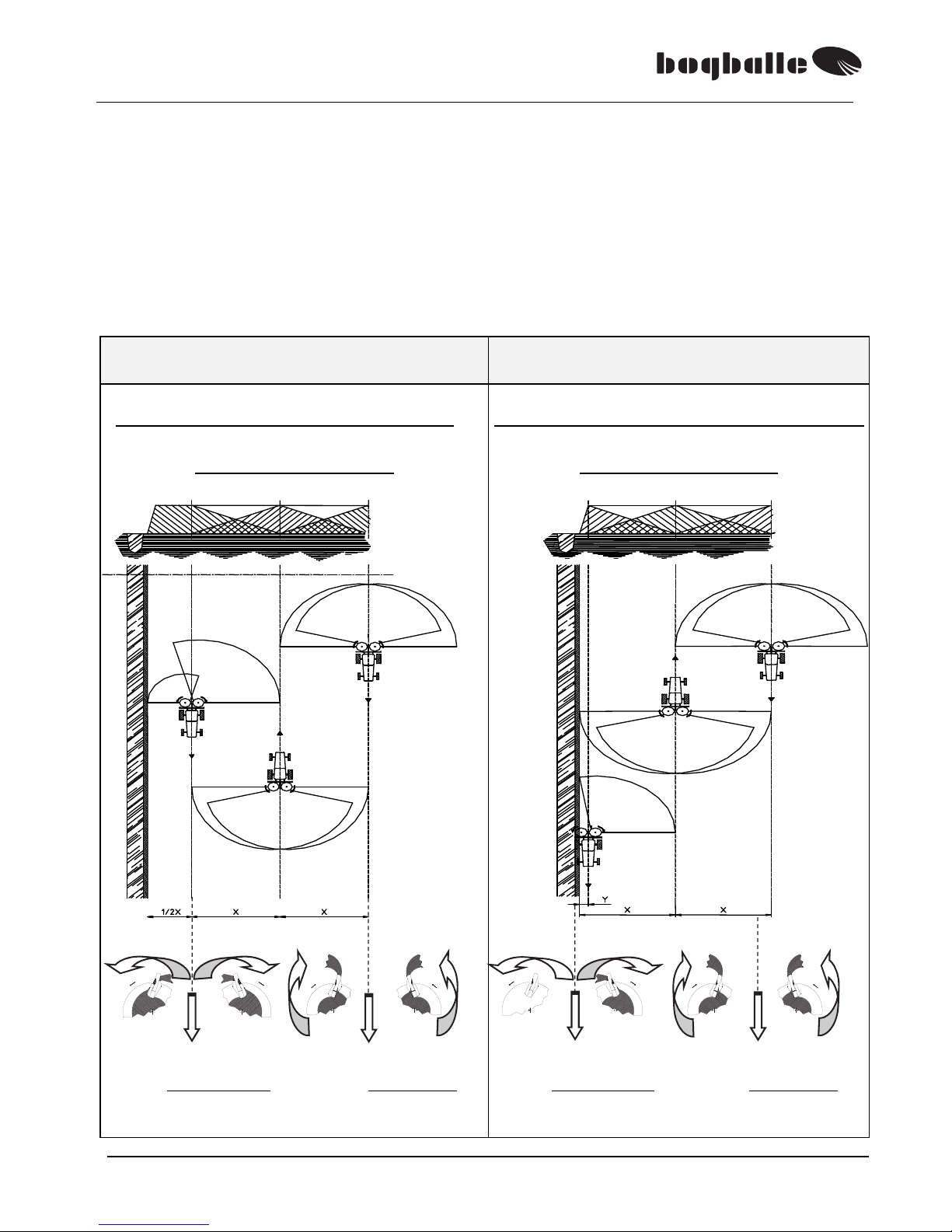
The spreading can be divided into two systems.
• A system for NORMAL spreading on the NORMAL area of the field.
• A system for HEADLAND spreading along the BORDER of the field.
The HEADLAND- spreading can again be divided into two systems, say:
• HEADLAND spreading TO BORDER – where distance from border to 1st
tramline is equal to ½ of the spread width.
• HEADLAND spreading FROM BORDER – where 1
st
tramline is placed close
to the border.
TO BORDER / NORMAL spreading FROM BORDER / NORMAL spreading
1st tramline: ½ of spread width from border 1st tramline: Along the border
HEADLAND spreading TO BORDER is
made with the spreading discs rotating –
away from eachother.
HEADLAND spreading FROM BORDER
is made with the spreading discs rotating –
away from eachother.
TO BORDER
Rotation away from centre
Spreading w/ R and L disc
NORMAL spreading
Rotation towards centre
Spreading w/ R and L disc
FROM BORDER
Rotation away from centre
Spreading w/ L disc
Right outlet closed
NORMAL spreading
Rotation towards centre
Spreading w/ R and L disc

M2(W) / M3(W) / M6W
21
NORMAL spreading
At the NORMAL spreading the machine is set as
stated under the paragraphs:
PTO-SPEED
TILT ANGLE
WORKING HEIGHT
QUANTITY SETTING
VANE/SPREAD WIDTH
The machine setting is based on spread tests made in BOGBALLE’s test hall. The
spreading abilities of the fertiliser in question may vary in comparison to the abilities
of the fertiliser which was tested at BOGBALLE – which formed the basis for the
spread chart.
The 4-double overlap of the machine, and the ”power suplus” of the spreading system – in
such cases gives extra tolerance for achieving a good spreading result – normally without
making corrections to the recommended setting.
The only correction that can be made is – change of the TILT-ANGLE of the machine.
Under normal conditions the machine settings recommended in the Operator’s Manual
and the Spread Charts of the spreader should not be changed – unless the fertiliser in
question is not stated in the spread chart or that the nature/quality deviates from ”what
you should expect”! For possible corrections see "PRACTICAL TEST".
PRACTICAL TEST
In case you want to make a practical test in the field, it is possible to place test trays
.
A such test must be carried out very carefully – and the test may if it is not done
correctly – be misleading.
Guidance is found under ”TEST WITH TEST TRAYS”.
Are not sold by BOGBALLE – information can be obtained from your dealer.
The test has the primary purpose – by adjustment of the TILT angle of the
machine – to ensure a correct spread width and thus a optimum overlap (see
examples of spread pattern on the following pages).
The 4-double overlap means that no kind of side adjustment is necessary.
As main rule the spread width will:
Be increased by approx. +1 metre for + 1° tilt.
Be reduced by approx. - 1 metre for - 1° tilt.
In case you have no test trays available the spread width can be checked by ensuring that
fertiliser is spread – as a minimum to the middle of the next tramline.
NORMAL
Shift handle in
inner position

M2(W) / M3(W) / M6W
22
TEST WITH TEST TRAYS
For a practical test in the field it is possible to use test trays in order to ensure a
correct spread width and thus an optimum overlap.
The tray test must be made with great care as wrong placement of the test trays
may result in faulty measuring and faulty setting of the machine.
BOGBALLE recommends normally only to use test trays in case the fertiliser type
spread is not found in the spread chart or in case you are not sure about the quality
of the fertiliser.
On the Internet you will find the latest spread charts updates on our home page:
www.bogballe.com
Included with the test trays you will find a description how to use them. Below you
will find a short description with an example of an 18 metres system where 7 test
trays are used and where the result is measured by means of 7 measuring tubes:
• Place the test trays in an even line across the driving direction.
• It is essential that the trays are placed HORIZONTALLY. (Use level).
SPREAD WIDTH
(metres)
TRAY DISTANCE
(metres)
12 1,5
15-16 2,0
18 2,5
20-21 3,0
24 3,5
27-28 4,0
30 4,5
32-33 5,0
36 5,5
42 6,5
For each 3 metres spread width – the
distance between the single trays is
increased by 0,5 metre.
• Start spreading minimum 10
metres before the row of trays.
• Stop spreading minimum 35
metres after the row of trays.
• Spread in 3 tramlines.
• Empty contents of each tray
down in each a measuring tube
and see the result.
Spread width
Tray distance

M2(W) / M3(W) / M6W
23
The contents of the test trays will indicate the distribution in the field.
The optimum setting is achieved – and a good variation coefficient is achieved.
The setting of the spreader gives an insufficient overlap. Insufficient overlap
means that an inadequate quantity is spread between the tramlines – and the
tilt angle of the machine must be adjusted in steps of +2°. Repeat the test.
The setting of the spreader gives a too large overlap. This means that a too
large quantity is given between the tramlines – and the tilt angle of the machine
must be adjusted in steps of -2°. Repeat the test.
Because the test tray system is not able to assemble all of the spread quantity –
because some grains will ”jump” out of the trays – you will have fluctuations of 1015% (See example
)
The test has as purpose to show a tendency in direction of:
Too SMALL overlap: TILT-angle is increased +2°, until tendency is
or
Too LARGE overlap: TILT-angle is decreased -2°, until tendency is
FOR THE SAKE OF GOOD ORDER…it is recommended to check as follows:
• Is the PTO speed correct?
• Is the distance between the tramlines correct?
• Is the spreading vanes mounted / set correctly?
• Are the spreading vanes intact?
• Is it a spread width or a fertiliser type, for which another vane type is necessary?
• Is the height of the spreader over the crop correct?
• Are the test trays correctly placed?
Example of the result if the test trays are not placed correctly.
5
°
misplacement makes a large difference of amount collected in the trays!
Optimum overlap
Too SMALL spread width/overlap
Tilt angle must be increased
Too LARGE spread width/overlap
Tilt angle must be decreased
Less collected
More collected
M2(W) / M3(W) / M6W
24
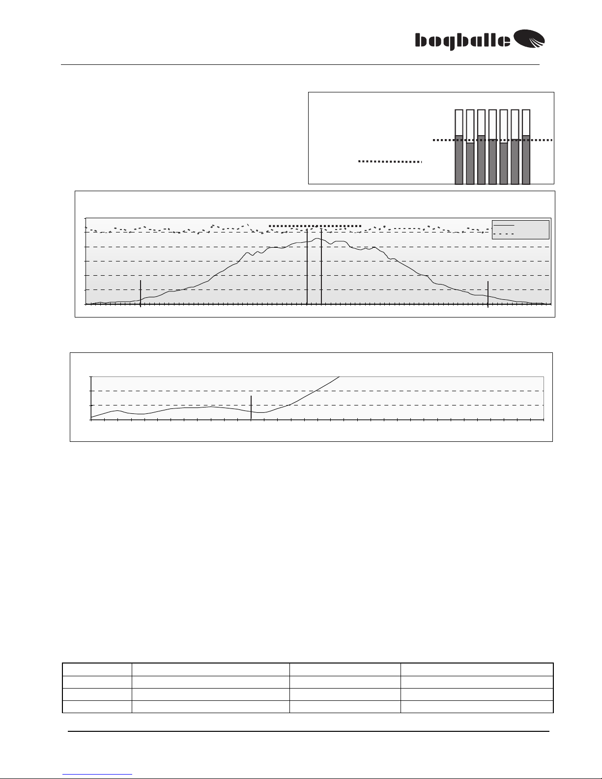
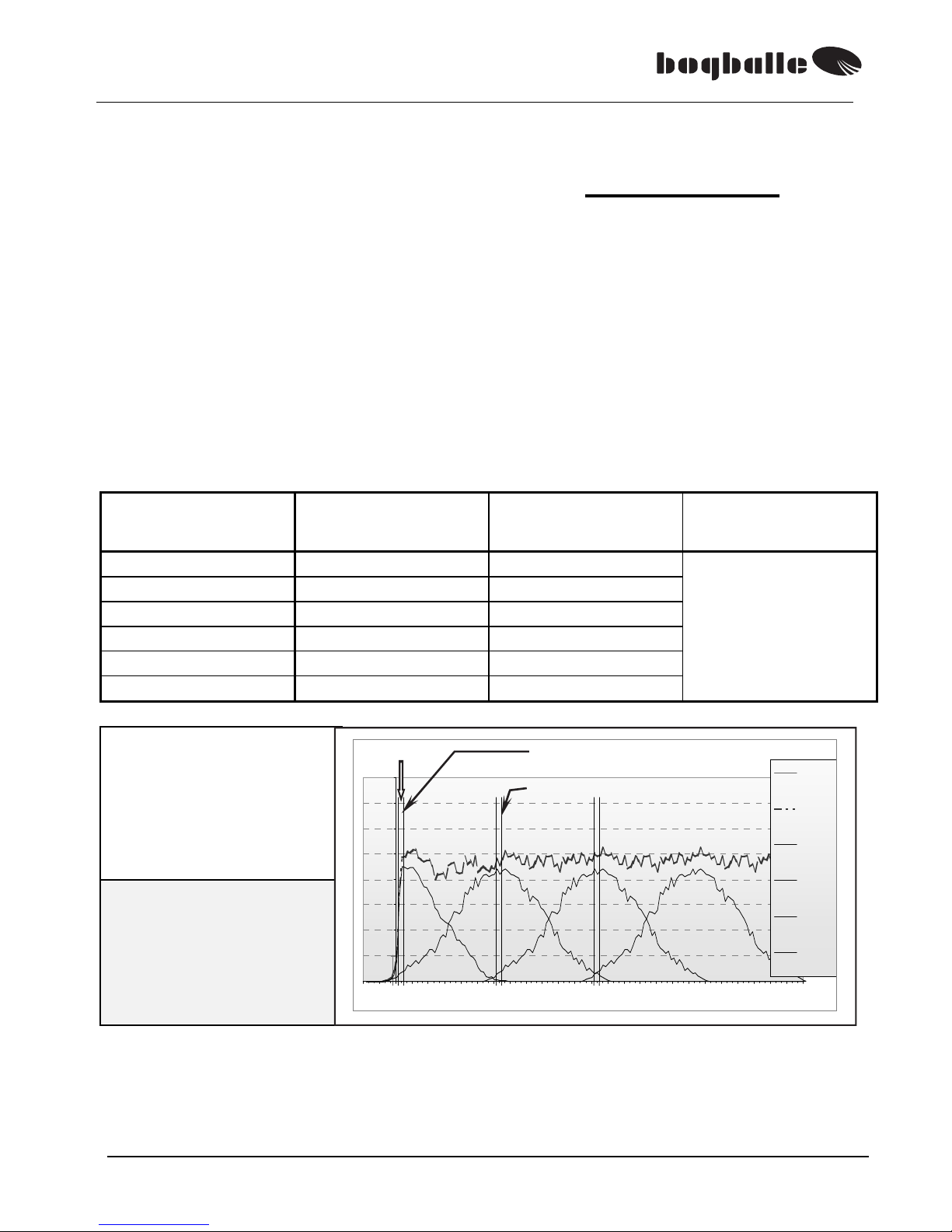
Examples for NORMAL spread patterns.
Spread width : 18 metres
Quantity : 250 Kg/Ha
Test with test trays
OPTIMUM spread pattern
TILT ANGLE: +3°
Tendency
Optimum overlap
From the tramline in which you drive the spread pattern forms a ”TRIANGLE”, ensuring a correct overlap.
The fertiliser in this example is as a minimum spread to next tramline – often wider.
The variation coefficient (Vk) is an expression of the ”quality” of the spread pattern.
In this example the VK is of optimum size at 18 metres – with a Vk of 2,9 %
The variation coefficient indicates the ability of the spreader to distribute the
fertiliser evenly over the field. If the spread width is either too large
(large overlap), or
too small (small overlap) – it will influence negatively the Vk and thus the fertiliser
distribution.
One of the big BOGBALLE strengths is that the 4-double overlap of the machine
ensures a good flexibility – say a minimum Vk – over a very very large spectrum.
(In this example from 6 to 21 metres).
This means in practice that the machine is able to absorb deviations in the distance
of tramlines, deviations in PTO speed and to a certain degree – deviations from tilt
angle, without influencing the distribution of the fertiliser (Vk).
As main rule the below scale is used internationally as evaluation basis:
Vk < 5 % Very good
Vk > 5 % < 10 % Good
Vk > 10 % < 15 % Acceptable
Vk > 15% < 20% Not acceptable
>20 might be visible in the crop
Sprede- og overlapningskurve
0
5
10
15
20
25
30
24 19 14 9 4 4 9 14 19 24
Meter
Gram
Spredekurve
Overlap 18m
Variationskoefficient
2,9%
0,0%
5,0%
10,0%
15,0%
6 7 8 9 10 11 12 13 14 15 16 17 18 19 20 21 22 23 24 25 26 27 28 29 30 31 32 33 34 35 36 37 38 39 40
Afstand mellem kørespor
Spread- and Overlap pattern
Variation Coefficient
Distance between tramlines

M2(W) / M3(W) / M6W
25
Spread width : 18 meter
Quantity : 250 Kg/Ha
Test with test trays
TILT- angle too SMALL
TILT ANGLE: 0°
Tendency
Too SMALL overlap
The ”DOWN BOW” of the spead pattern shows that there is not sufficient overlap between the tramlines.
The TILT- angle is increased in steps of + 2°
In this example the Vk is optimum at 15 metres – with a Vk of 4,5 %
Spread width : 18 metres
Quantity : 250 Kg/Ha
Test with test trays
TILT- angle too LARGE
TILT ANGLE: +6°
Tendency
Too BIG overlap
The ”UP BOW” of the spread pattern shows that there is too large overlap between the tramlines.
The TILT angle is decreased in steps of - 2°
In this example the Vk optimum at 21 metres – with a Vk of 4,0 % - and 18 metres with a Vk of 5,4%
If you doubt, it is better to tilt the machine TOO MUCH – than too little.
0
5
10
15
20
25
30
35
24 19 14 9 4 4 9 14 19 24
Meter
Gram
Spredekurve
Overlap 18m
Variationskoefficient
0,0%
5,0%
10,0%
15,0%
6 7 8 9 10111213141516171819202122232425262728293031323334353637383940
Afstand mellem kørespor
Sprede- og overlapningskurve
0
5
10
15
20
25
30
35
24 19 14 9 4 4 9 14 19 24
Meter
Gram
Spredekurve
Overlap 18m
Variationskoefficient
5,4%
0,0%
5,0%
10,0%
15,0%
6 7 8 9 10 11 12 13 14 15 16 17 18 19 20 21 22 23 24 25 26 27 28 29 30 31 32 33 34 35 36 37 38 39 40
Afstand mellem kørespor
Variation Coefficient
Spread and Overlap pattern
V
ariation Coefficient
Spread and Overlap pattern
Distance between tramlines
Distance between tramlines
M2(W) / M3(W) / M6W
26
HEADLAND spreading, TO BORDER, with border to the right in the driving direction.
The BOGBALLE machine can optionally
…..be changed to HEADLAND spreading – without leaving the tractor cab.
This way you have a very user friendly system – which ensures at the same time
optimum headland spreading.
While spreading on HEADLAND the NORMAL settings of the machine are
retained – except:
THE ROTATION DIRECTION OF THE SPREADING DISCS
The back side of the vane is used
ALWAYS STOP PTO when changing the rotation direction!
PTO- SPEED
QUANTITY SETTING / SPEED
(Only at spread widths from 12 to 18 metres).
At spread widths from 19 to 42 metres the quantity is NOT reduced.
• It must be considered that the fertiliser when spreading on HEADLAND – will to a
higher extent than in NORMALspreading – be thrown forwards in the driving direction.
The rotation direction is changed so that the spreading discs rotate ”away from
centre”. (See FUNCTION OF SPREADING VANE / Trend SYSTEM) Is done manually or by
cable.
The PTO speed is reduced in order to limit the spread width.
There is a direct connection between the PTO speed and the HEADLAND
spread width.
The higher PTO speed – the wider HEADLAND spread width.
This means in practice that it is possible to ”choose” the required
HEADLAND
spread width – depending on the wish of spreading FULL quantity TO
BORDER, or if a REDUCED quantity TO BORDER is required.
(See examples
of HEADLAND spread patterns , og ).
The quantity is reduced either by reducing the outlet (setting system) or by
increasing the forward speed. The quantity is changed in comparison to the
PTO speed.
(Only at spread widths from 12-18 m).
HEADLAND
Shift handle in outmost position

M2(W) / M3(W) / M6W
27
HEADLAND-spread width can be mentioned as 3 categories:
Rate reduction
MINIMUM
Minimum quantity over border
- - 20 %
MEDIUM
Medium quantity 25-70% at border
- - 10 %
MAXIMUM
Maximum quantity to border
- - 0 %
So it is possible by the PTO-speed to decide the character of the HEADLAND spreading
(See HEADLAND spread patterns TO BORDER , and ).
SPREAD WIDTH
[Metres]
MINIMUM
-20%
PTO-(rpm.)
MEDIUM
-10%
PTO-(rpm.)
MAXIMUM
PTO-(rpm.)
12 metres 200 rpm. 250 rpm. 300 rpm.
15-16 metres 250 rpm. 300 rpm. 350 rpm.
18 metres 300 rpm. 350 rpm. 400 rpm.
21 metres 350 rpm. 400 rpm. 450 rpm.
24 metres 400 rpm. 450 rpm. 500 rpm.
28 metres
See the instruction included with the E6-T & E8-T vanes.
32 metres
36 metres
42 metres
If full coverage must be achieved to border up to 24 metres, it is possible to increase
MAXIMUM PTO rpm. by 50 rpm.
When reducing the PTO speed – and thus reduction of the spread width – the
application rate must be reduced accordingly in order to achieve a constant rate
(Kg/Ha):
The quantity can be reduced either by:
• reducing the application rate direct by the % adjustment of the CALIBRATOR - or
• increasing the forward speed according to the following chart.
If the application rate is reduced by increasing the forward speed, the below chart can be followed.
Forward speed
HEADLAND spreading
+ 20%
Forward speed
HEADLAND spreading
+ 10%
Forward speed
HEADLAND spreading
+ 0%
Forward speed
NORMAL spreading
MINIMUM
MEDIUM
MAXIMUM
8,0 Km/h
9,6 Km/h 8,8 Km/h 8,0 Km/h
10,0 Km/h
12,0 Km/h 11,0 Km/h 10,0 Km/h
12,0 Km/h
14,4 Km/h 13,2 Km/h 12,0 Km/h
14,0 Km/h
16,8 Km/h 15,4 Km/h 14,0 Km/h
Example: Required pattern is the MEDIUM HEADLAND spread pattern
Forward speed for NORMAL spreading is 8,0 Km/h
Forward speed for HEADLAND spreading must be increased to 8,8 Km/h

M2(W) / M3(W) / M6W
28
PRACTICAL TEST
In case you want to make a practical test in the field it is possible to place test trays in the
field
. Such a test must be done very carefully - and the test can if it is not correct - be
misleading.
Not sold by BOGBALLE - information available from your dealer.
The test has a primary purpose - by adjusting the PTO rotations on the machine, to ensure
the required spreading to BORDER
(see examples of HEADLAND spread patterns to border on the next pages).
As main rule the HEADLAND spread width will:
Be increased by approx. +1 meter for each + 50 rpm.
Be decreased by approx. -1 meter for each – 50 rpm.
If the PTO-rotations are changed in relation to the three categories, respectively:
Minimum, Medium and Maximum - the quantity also has to be changed,
respectively:
+50 rpm / +10% and -50 rpm. / –10%
TEST WITH TEST TRAYS
• The test trays are placed as shown on the sketch and with the distance stated in the
table.
• The purpose of the test is to determine how large a quantity is landing AT
BORDER - in proportion to the GENERAL AREA of the field.
• The machine is adjusted in such way a MEDIUM- headland spreading is
achieved, with 25 – 70 % of the quantity of the GENERAL area AT BORDER.
SPREAD WIDTH (m) TRAY DISTANCE (m)
12 1,0
15-16 1,5
18 2,0
20-21 2,5
24 3,0
27-30 3,5
32-33 4,0
36 4,5
42 5,5
MEDIUM : 25 to 70 % at border / (0,25 – 0,70)
MINIMUM : -50 rpm. / - 10 %
MAXIMUM :
+50 rpm. / +10%
MEASURING and CALCULATION
• Quantity AT BORDER:
The contents in the 3 trays AT BORDER is
added and the quantity is divided by 3.
• Quantity OVER GENERAL AREA:
The contents in the 4 trays in GENERAL AREA
is added and the quantity is divided by 4.
Quantity AT BORDER is divided with
QUANTITY IN GENERAL AREA.
Is the result between 0,25 and 0,70 the spread
pattern on headland corrsponds a MEDIUM
pattern.
Is the result not between 0,25 and 0,70 the
machine is set respectively ±50 rpm. / ±10%,
until a MEDIUM pattern is achieved.
MINIMUM / MAXIMUM is achieved by
changing PTO by ± 50 rpm and change the
q
uantity by ± 10% respectively.
Tray distance
Tra
y 1,
2 and 3
3 2 1

M2(W) / M3(W) / M6W
29
Examples of HEADLAND spread patterns – TO BORDER.
Spread width : 18 metres
NORMAL quantity :250 Kg/Ha
HEADLAND qty. : 200 Kg/Ha
PTO speed : 300 rpm.
Speed increased from: 8,0Km/h
+ 20% 9,6 Km/h
PTO 300 rpm.
HEADLAND- result:
• Full quantity achieved app.
2,5 metres into the field
• Approx. 1,5 meter is spread
outside border.
Spread width : 18 metres
NORMAL quantity :250 Kg/Ha
HEADLAND qty. : 225 Kg/Ha
PTO speed : 350 rpm.
Speed increased from:
8,0
Km/h
+ 10% 8,8 Km/h
PTO 350 rpm.
HEADLAND result:
• Full quantity achieved app.
2 metres into the field.
• Approx. 2,5 metres are
spread outside border.
Spread width : 18 metres
NORMAL quantity 250 Kg/Ha
HEADLAND qty. : 250 Kg/Ha
PTO speed : 400 rpm.
Speed increased from:8,0 Km/h
+ 0% 8,0 Km/h
PTO 400 rpm.
HEADLAND result:
• Full quantity achieved app.
1 metre into the field
• Approx. 3,5 metres are
spread outside border.
0
5
10
15
20
25
30
35
40
45
-6 -3 0 3 6 9 12151821242730333639424548515457606366697275
Gødningsgrænse
Sum curve
Sum kurve
1 st. Tramline
1. Kør espor
2 nd. Tramline
2. Kør espor
3 rd. Tramline
3. Kør espor
Tra mlines
Kør es p or
0
5
10
15
20
25
30
35
40
45
-6-3036912151821242730333639424548515457606366697275
Gødningsgrænse
Sum curve
Sum kurve
1 st. Tramline
1. Kørespor
2 nd. Tr amline
2. Kørespor
3 rd. Tramline
3. Kørespor
Tra mlines
Kørespor
0
5
10
15
20
25
30
35
40
45
-6 - 3 0 3 6 9 12 15 18 21 24 27 30 33 36 39 42 45 48 51 54 57 60 63 66 69 72 75
Gødningsgræns e
Sum curve
Sum kurv e
1 st . Tramline
1. Kørespor
2 nd. Tramline
2. Kørespor
3 rd. Tramline
3. Kørespor
Tr a mlines
Kørespor
MINIMUM
MEDIUM
MAXIMUM

M2(W) / M3(W) / M6W
30
HEADLAND spreading, FROM BORDER, with border to the right in the
driving direction
(Option)
The BOGBALLE machine can be changed to HEADLAND spreading – without
leaving the tractor cabin.
While spreading on HEADLAND the NORMAL settings of the machine are retained except:
THE ROTATION DIRECTION OF THE SPREADING DISCS
Deflector is tilted down
Close right outlet of the spreader
The right agitator is stopped
The back side of the vane is used
ALWAYS STOP PTO when changing the rotation direction!
PTO- SPEED
• It must be considered that the fertiliser when spreading on HEADLAND – will to a
higher extent than at NORMAL spreading – be thrown forwards in the driving direction.
All above ”switches” are made in one ”switch” – via link arms
– and at the same time the rotation direction of the spreading discs is reversed
The rotation direction of the spreading discs is changed so that the spreading
discs rotate ”away from center”. (See FUNCTION OF SPREADING VANE / Trend
SYSTEM) Is done manually or by cable.
The PTO- speed is reduced in comparison to the NORMAL spread width.
HEADLAND
rotation direction
Made by one shift
M2(W) / M3(W) / M6W
31
The HEADLAND pattern FROM BORDER will only to a limited degree
be changed when changing the PTO rpms.
Examples of HEADLAND spread pattern, FROM BORDER.
The HEADLAND spreading system FROM BORDER, is developed for spread
widths from 12 – 28 metres. In case spread widths larger than 28 metres are
required – it will not be suitable to use this system – the system TO BORDER must
be used.
The HEADLAND spreading system FROM BORDER, is developed so that the
PTO– speed is reduced in comparison to the spread width.
• The ”power surplus” of the spreader means that the spread pattern overlaps
the tramlines closest to the tramline in which the spreading is made. This
means that fertiliser from 2
nd
tramline will be thrown outside the border –
unless the PTO speed is reduced in 2
nd
tramline. The reduction
corresponds to the PTO- speed FROM BORDER (See chart).
SPREAD WIDTH
[Metres]
PTO- speed
FROM BORDER
PTO- speed
2nd tramline
PTO- speed
Rest
12 metres 350 rpm. 350 rpm.
540
rpm.
15-16 metres 400 rpm. 400 rpm.
18 metres 450 rpm. 450 rpm.
21 metres 500 rpm. 450 rpm.
24 metres 540 rpm. 540 rpm.
28 metres 540 rpm. 540 rpm
Spread width : 18 metres
NORMAL rate : 250 Kg/Ha
HEADLAND rate : 250 Kg/Ha
PTO speed : 450 rpm.
Forward speed : 8,0 Km/h
PTO 450 rpm.
HEADLAND- result:
• Full quantity achieved app.
0,5 meter into the field.
• Approx. 0,5 meter is spread
outside border.
From the pattern it must be considered that the full quantity is not spread absolutely
out to the border but that the fertiliser quantity is increasing from 0% in border and
up to 100% approx. 0,5 – 1 metre into the field. This depends on how close the
tractor is driven to the border.
The closer to the border – the closer the full rate to border.
0
5
10
15
20
25
30
35
40
-6 - 3 0 3 6 9 12 15 18 21 24 27 30 33 3 6 39 4 2 45 48 51 54 57 60 63 66 69 72 7 5
Gød ni ngsg r ænse
Sum curve
Sum kurv e
1 st. Tramline
1. Køres por
2 nd. Tramlin
e
2. Køres por
3 rd. Tramline
3. Køres por
Tr a mlines
Kør e s p o r
HEADLAND, FROM BORDER
2ndtramline, reduced PTO.
M2(W) / M3(W) / M6W
32
The HEADLAND spreading system, FROM BORDER, is developed
for considering the environment as much as possible – and
considering at the same time the demands for optimum yield.
• Please consider that the distance between the tramlines must be equal to the
spread width.
• If first tramline is placed 1 metre from border – the distance from border
to next tramline must be equal to the spread width + 1 metre.
See the above pattern: First tramline = 1 metre from border.
Second tramline = (18 + 1) = 19 metres from border.
REDUCED SPREAD WIDTH
In case it is necessary to reduce the spread width, for instance when spreading on
a narrower final bout in the field, or in connection with non rectangular parts in the
field – the spread width can be limited by either tilting the spreader negatively or by
reducing the PTO- rpms.
REDUCED PTO- speed:
• When reducing by 75 rpm. the NORMAL spread width is reduced by 2 metres.
• At the same time the quantity must be reduced to the relation between the
NORMAL spread widht and the REDUCED spread width.
• The reduction of quantity can be adjusted by increasing the driving speed
respectively, if this is easier.
Example:
NORMAL
Spread Width
REDUCED
Spread Width
PTO rpm.
NORMALspreading
PTO = 540 rpm.
Speed
Example:
Speed = 10,0 Km/h
Quantity
Reduction
12 metres 10 metres (540 – 75) = 465 (12/10) x 10,0 = 12,0 - 17 %
15 metres 13 metres (540 – 75) = 465 (15/13) x 10,0 = 11,5 - 13 %
18 metres 16 metres (540 – 75) = 465 (18/16) x 10,0 = 11,3 - 11 %
18 metres 14 metres (540 – 150) = 390 (18/14) x 10,0 = 12,9 - 22 %
REDUCED TILT- angle:
• If the tractor is equipped with hydraulic top link a reduction of the tilt-angle of
-2° will reduce the NORMAL spread width with 2 metres.
• At the same time the quantity must be reduced according to the above
instruction.
-2˚
M2(W) / M3(W) / M6W
33
TURNINGS AT THE HEADLANDS
When turning at the headlands, the below OPEN / CLOSE instructions should be
followed.
• If the instructions are followed the result will be full overlap to the end of the
field and no fertiliser is spread outside the field.
• The OPEN / CLOSE distance from TRAMLINE depends on the spread
width.
Please note that the OPEN / CLOSE distance for the NORMAL spreading, are not
identical in connection with HEADLAND spreading TO BORDER and FROM
BORDER resp.
TO BORDER / NORMAL spreading
SPREAD-
WIDTH
OPEN
Distance from
TRAMLINE
CLOSE
Distance to
TRAMLINE
12 metres 8 metres 6 metres
15 metres 13 metres 6 metres
16 metres 14 metres 6 metres
18 metres 15 metres 6 metres
20 metres 16 metres 6 metres
24 metres 18 metres 6 metres
28 metres 20 metres 6 metres
32 metres 22 metres 7 metres
36 metres 24 metres 8 metres
42 metres 27 metres 11 metres
45 metres 29 metres 12 metres
FROM BORDER / NORMAL spreading
SPREAD-
WIDTH
OPEN
Distance from
TRAMLINE
CLOSE
Distance
from
HEADLAND
12 metres 8 metres minimum
15 metres 13 metres minimum
16 metres 14 metres minimum
18 metres 15 metres minimum
20 metres 16 metres minimum
24 metres 18 metres minimum
28 metres 20 metres minimum
CLOSE as close to BORDER as possible. (”minimum”)
M2(W) / M3(W) / M6W
34
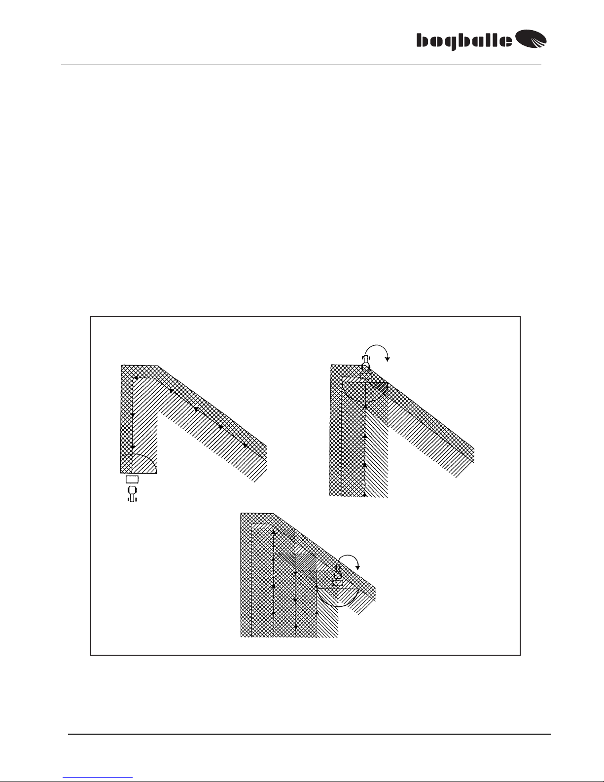
SPREADING ON NON RECTANGULAR FIELDS
When spreading in non rectangular fields, it is often the opinion that one side of the
maschine should be closed in order to achieve a good result. Closing one side of
the machine results in sharp overlaps in the areas where the closing is done.
Spreaders where the spreading discs are rotating towards eachother ensures ”soft
overlaps” when spreading in non rectangular areas of the field – and one side of
the machine should not be closed.
• At first the HEADLAND spreading is made.
• Afterwards you spread in normal way – in the tramlines. (See sketch)
• The OPEN / CLOSE time depends on the angle of the field and OPENING /
CLOSING must be done in comparison to the spread width.
Opening and closing of the spreader outlets is made as shown on the sketch.
It may be necessary in narrow angled areas to spread with REDUCED SPREAD WIDTH.
Example for spreading on non-rectangular fields

M2(W) / M3(W) / M6W
35
CHECKS OF TRACTOR – before use
It is important that the lift arms of the tractor are set horizontally.
If this is not the case the spreader will ”tilt” and the fertiliser will not
spread equally to both sides of the spreader.
Result: Asymmetric spread pattern.
The spread width depends on the rotation speed of the spreading
discs. Therefore the PTO- rotations should be kept constant at 540
rpm.There are often differences in the tractor meter. Therefore make
it a rule to check the rotation speed of the PTO from time to time.
The quantity in [Kg/Ha] is directly dependant on the forward speed.
Therefore the speed [Km/h] must be kept constant.
There are often differences in the tractor meter. Therefore make it a
rule to check the driving speed from time to time.
CHECK OF SPREADER- before use.
The adjustment and closing shutters must be easy to move. Never
use force. If the system is not easy to move – the reason is often lack
of lubrication of the moving part of the setting system.
The spreading discs must turn easily when the PTO is not mounted.
• Agitators must turn easily.
• Turnable outlet must be easy to turn.
• Regulating outlets must be easy to turn.
• The speading vanes must be intact and correctly fixed.
The PTO shaft must be of correct length, with suitable overlap
of the axle ends (min. 50 mm.). If the overlap is too long or too
short it will result in a serious damage of the transmission axle.
• DO NOT lift the spreader higher than working height.
If the shaft is not of correct length –
and if the transmission is damaged, it
will clearly appear from ”press marks
” on the splined axle.
A such damage is of course not under
warranty.
•
In case the spreader ”leaks” fertiliser – when
the outlets are closed – this is due to the
distance between tighteneing part and
hopper bottom being more than 0,5 mm.
Loosen the tightening part and press towards
hopper bottom so that the distance is 0,5 mm.

M2(W) / M3(W) / M6W
36
PRACTICAL HINTS
• Prevent ”packing” the fertiliser by driving over long distances on uneven ground
with a full hopper. If the fertiliser is “packing” in the bottom of the hopper it might
mean damage to the agitator of the machine.
• The spreading discs should not rotate for long periods when the shutters are
closed. The fertiliser will pack and thus cause squeezing between shutter and
agitator. The ”fingers” of the agitator might be damaged and in worst case
”break”.
• When spreading ”dusty” fertiliser, it is necessary to regularly clean the base of
each side of the hopper to prevent build up of fine material which could pack
thus causing squeezing between shutter and agitator. The ”fingers” of the
agitator might be damaged and in worst case ”break”.
• The machine should not be used without cone (over the agitator).
• Do not fill fertiliser into a wet hopper. The humidity will make it difficult for the
fertiliser to fall down and thus reduce the quantity. Take care particularly when
calibrating manually. If the hopper is wet (water or oil), more calibration tests
must be made before having a correct calibration quantity.
• Be aware that in the transmission, there is a gearing of 1:1,39. The number of
PTO- rotations is therefore not corresponding to the number of rotations on the
spreading discs.
• PTO = 540 rpm.
• Spreading discs = 750 rpm.
• When driving in wet field and at high speed, mud, stones or may be water may
be thrown up into the hopper from the rear wheels of the tractor. In such cases
it is recommended to use the BOGBALLE hopper cover.
• When driving in wet field and at high speed, mud, stones or similar might be
thrown up into the spreading system. That means collision with the spreading
vanes – which means again defect / bended vanes. In such cases it is
recommended to use BOGBALLE mud guards.
MOUNTING OF OPTIONAL EQUIPMENTS
Mounting and operation instructions are included with the options from the
factory. Ask the dealer to let you have the instructions – after mounting.
It is strongly recommended to grease all of the machine in oil
or a similar corrosion protection liquid – BEFORE the
machine is used first time.
This way the assemblings of the machine and also the areas, in which
there is later not sufficiant cleaning, are corrosion protected.
Repeat greasing each time the machine was cleaned.

M2(W) / M3(W) / M6W
37
M()W – special
BOGBALLE M()W ……….the ultimative solution!
The M2W and M3W machine is respectively equipped with one and two parallel
mounted 6 tons stainless load cells, which makes it possible together with
CALIBRATOR – to have complete control during the field work.
The weighing system is so constructed that the parallel mounted hopper and
spreading system is carried through 2 blade springs and 2 bearings.
• The parallel construction ensures that the weight is always correct and stable
– no matter where in the hopper the load is placed. This way a maximum
precision is ensured independent of load circumstances.
• The parallel construction ensures moreover that the precision in the weighing
result ist within ± 1%, even in case it goes uphill or downhill with gradients of
7-8% (6°-7°).
M2W has a capacity of max. 2.500 kg, and the max. capacity of the M3W machine is 4.000 kg. Example
(M3W):Together with the weight of the machine it makes a total load of approx. 4.750 kg. In case the
ground is very uneven it means that the weighing system is up against loads of 2 x the total load – say
2 x 4.750 kg = 9.500 kg.
The M()W machine will ”settle”
after spreading 5 – 10 tonnes of
fertiliser.
This means that the 0- point can
be moved.
Is this the case make a
calibration / 0-setting of the
system.
(See Operator’s Manual for the
CALIBRATOR)
The blade springs must always
be horizontal in comparison to
the chassis tube. If this is not the
case – adjust the system by the
adjustment bolt.
After adjustment the system
must always be calibrated.
The bearing should not be
washed directly with water – and
special care must be taken when
cleaning the load
cell.
Possible defects due to water, are
not under warranty.
Blade spring
Load cell
Adjustment bolt
Bearing

M2(W) / M3(W) / M6W
38
How to use the quadro calibration system
BOGBALLE M-line is as standard equipped with the quadro calibration system
which is used for adjusting the spreader’s quantity and for rest emptying (see the
enclosed quadro folder).
The system is used for stationary calibration in order to precisely adjust the
spreader according to the fertiliser’s condition - as the temperature, air humidity
and other climate conditions might influence on the fertiliser flow.
Please notice that the fertiliser’s condition can vary from each delivery. It’s
advised to carry out a new calibration for each delivery.
If the hopper is moist on the inside the moisture will prevent the fertiliser from
gliding. In these cases it’s advised to carry out a minimum of three calibrations
– the last calibration value being the one that counts.
PROCEDURE:
(We also refer to the quadro folder which illustrates the practical usage)
1. The scale stop is fixed at 4,5 on the spreader’s scale
2. Let the PTO-shaft rotate at 200-250 rpm.
(The spreader’s flow is constant with PTO rotations between 200-540 rpm.)
3. A calibration test is performed for exactly 30 sec.
(The spreader’s outlet is opened for 30 sec.).
4. The calibration value is weighed
5. The fertiliser’s Flow Factor is calculated cf. the below formula:
Quantity [Kg/Ha] x Spread width [M] x Speed [Km/h]
Calibration value [Kg/
30 sec.
]
6. In the Flow Factor list on the next page you can find the Flow Factor closest to
the calculated Flow Factor – read off the scale figure or use the Flow Factor
directly and adjust the spreader’s scale.
Symbol explanation:
[Kg/Ha]
: The wanted quantity
[M]
: Spread width
[Km/h]
: Speed
: Calibration value after 30 sec. at scale figure 4,5
: Scale 0-9, Flow Factor 645-6575
M2(W) / M3(W) / M6W
39
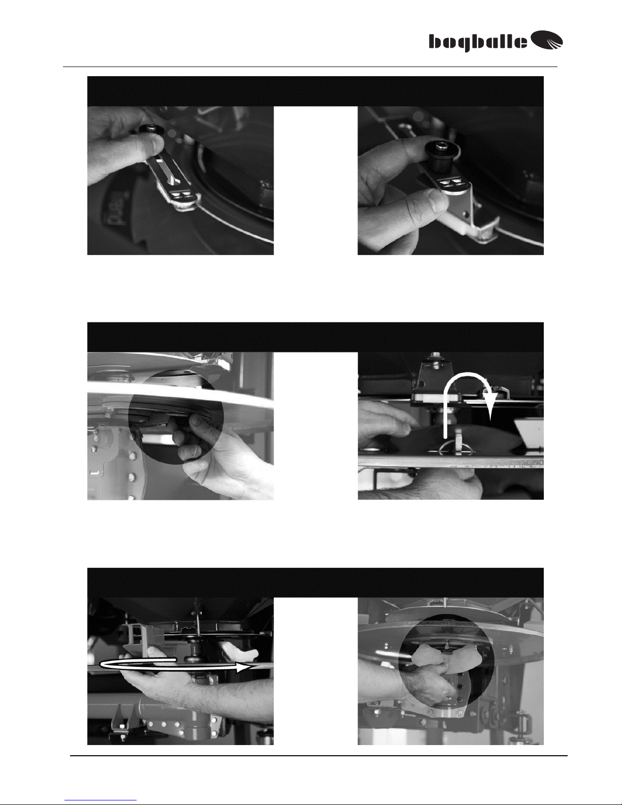
A: Lift up
B: Move
C: Remove handwheel D: Remove lid
E: Turn disc F: Lock
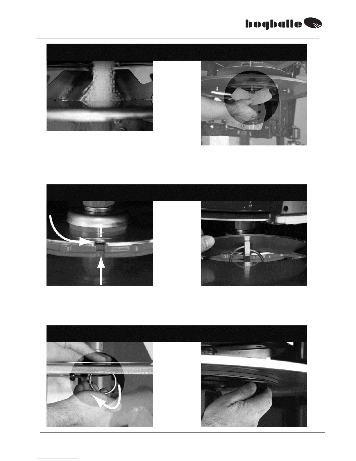
M2(W) / M3(W) / M6W
40
PTO = 200-250 rpm.
30 sek.
G: Calibrate 30 sec.
H: Remove lid
I: Turn hubs in position J: Insert lid
K: Lock L: Fasten handwheel

M2(W) / M3(W) / M6W
41
M: Lift up
N: Move back
O: Weigh (kg) P: Make calculation
E: Turn disc F: Lock
M2(W) / M3(W) / M6W
42
Flow Factor Calculation
4,5
PTO
250 rpm
[Kg/Ha] x [M] x [Km/h]
[ Kg]
=
Flow Factor
[Kg/Ha] [M] [Km/t]
Kg
Flow
Factor
NPK 21-3-10 : 300 X 24 X 12 / 25,7 = 3362 ► 5,2
: X X / =
►
: X X / =
►
: X X / =
►
: X X / =
►
: X X / =
►
: X X / =
►
: X X / =
►
: X X / =
►
: X X / =
►
Flow
Factor
Flow
Factor
+40%
Flow
Factor
-40%
Flow
Factor
F
L
O
W
F
A
C
T
O
R
0,0 1380 3,0 4080 6,0 3875 6,0 0 0,0
0,1 1470 3,1 4170 6,1 3940 6,1 15 0,1
0,2 1560 3,2 4260 6,2 4005 6,2 30 0,2
0,3 1650 3,3 4350 6,3 4070 6,3 45 0,3
0,4 1740 3,4 4440 6,4 4135 6,4 60 0,4
0,5 1830 3,5 4530 6,5 4200 6,5 75 0,5
0,6 1920 3,6 4620 6,6 4265 6,6 90 0,6
0,7 2010 3,7 4710 6,7 4330 6,7 105 0,7
0,8 2100 3,8 4800 6,8 4405 6,8 120 0,8
0,9 2190 3,9 4890 6,9 4480 6,9 140 0,9
1,0 2280 4,0 4980 7,0 4555 7,0 160 1,0
1,1 2370 4,1 5065 7,1 4630 7,1 190 1,1
1,2 2460 4,2 5150 7,2 4705 7,2 230 1,2
1,3 2550 4,3 5235 7,3 4775 7,3 270 1,3
1,4 2640 4,4 5320 7,4 4845 7,4 330 1,4
1,5 2730 4,5 5405 7,5 4915 7,5 390 1,5
1,6 2820 4,6 5490 7,6 4985 7,6 450 1,6
1,7 2910 4,7 5575 7,7 5055 7,7 510 1,7
1,8 3000 4,8 5655 7,8 5125 7,8 570 1,8
1,9 3090 4,9 5735 7,9 5195 7,9 630 1,9
645 2,0 3180 5,0 5815 8,0 5265 8,0 690 2,0
715 2,1 3270 5,1 5895 8,1 5335 8,1 760 2,1
785 2,2 3360 ►5,2 5975 8,2 5405 8,2 830 2,2
855 2,3 3450 5,3 6050 8,3 5475 8,3 900 2,3
930 2,4 3540 5,4 6125 8,4 5545 8,4 970 2,4
1005 2,5 3630 5,5 6200 8,5 5615 8,5 1040 2,5
1080 2,6 3720 5,6 6275 8,6 5675 8,6 1115 2,6
1155 2,7 3810 5,7 6350 8,7 5735 8,7 1190 2,7
1230 2,8 3900 5,8 6425 8,8 5795 8,8 1265 2,8
1305 2,9 3990 5,9 6500 8,9 5855 8,9 1340 2,9
Note: Below scale 2,0 or Flow Factor 645 use a higher speed.
Do not use the FLOW FACTOR, spreading fine granulated material.
By means of reduction outlet, do use the respective spread chart!
Option: ±40% needs the connection
rod no. 6381-23 or 6381-29.
Note: Do not use the Flow Factor
±40% directly on the scale. Do use
upper listed factor, then read scale
figure to adjust the scale on the
machine.
►
►
30 sec.

M2(W) / M3(W) / M6W
43
EC-Declaration of Conformity
Manufacturer:
BOGBALLE A/S
Bogballe · DK-7171 Uldum
Phone +45 7589 3266 Fax +45 7589 3766
Declares that machine:
Centrifugal fertiliser spreader:
M2(W) / M3(W)
Is made in conformity with:
directive of 17th May 2006 conc. mutual approximation of the laws of the member states on
machines (2006/42/EØF), with special reference to the enclosure II, A and enclosure I of the
directive, conc. essential safety and health claims in connection with construction and
manufacture of machines.
International/national standards:
DS/EN ISO 12100-1 og DS/EN ISO 12100-2
DS/EN ISO 13857
1st edition – 2008.03.26
DS/EN 349
DS/EN 14017 + A2
3rd edition – 2009.07.17
ISO 500,
1st edition – 2004.02.01
DS/EN ISO 4254-1 :2008
When mounted with CALIBRATOR:
Is made in conformity with:
directive of 15th December 2004 conc. mutual approximation of the laws of the member states on
electromagnetic compatibility (2004/108/EØF)
International/national standards:
DS/EN ISO 14982 :2009
DS/EN 61000-6-3 :2007
DS/EN 61000-6-4 :2007
Bogballe, 2013-09-01
Nils Jørn Laursen

M2(W) / M3(W) / M6W
44
Pictogram
Read Operator’s Manual and safety rules before
starting.
Stay under the machine is prohibited.
Safety distance for flying material must be
observed.
Avoid contact with rotating parts.
Avoid contact as long as parts are moving.
Do not spray water in this area.
< 70 dB (A)
Noise level of the machine is below 70 dB (A)
1: YEAR / 2002
2: NET. Kg standard machine / Total: See
manual

M2(W) / M3(W) / M6W
45
NOTES:
____________________________________
____________________________________
____________________________________
____________________________________
____________________________________
____________________________________
____________________________________
____________________________________
____________________________________
____________________________________
____________________________________
____________________________________
____________________________________
____________________________________
____________________________________
____________________________________
____________________________________
____________________________________
____________________________________
____________________________________

M2(W) / M3(W) / M6W
46
NOTES:
____________________________________
____________________________________
____________________________________
____________________________________
____________________________________
____________________________________
____________________________________
____________________________________
____________________________________
____________________________________
____________________________________
____________________________________
____________________________________
____________________________________
____________________________________
____________________________________
____________________________________
____________________________________
____________________________________
____________________________________

M2(W) / M3(W) / M6W
47
NOTES:
____________________________________
____________________________________
____________________________________
____________________________________
____________________________________
____________________________________
____________________________________
____________________________________
____________________________________
____________________________________
____________________________________
____________________________________
____________________________________
____________________________________
____________________________________
____________________________________
____________________________________
____________________________________
____________________________________
____________________________________
 Loading...