

Page 1
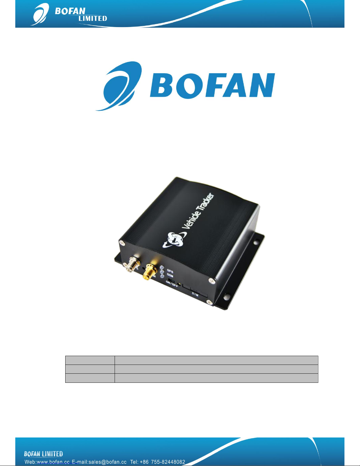
PT600X User Manual
Document Title
PT600X User Manual
Version
1.42.6
Date
2014-01-01
Page 2

Contents
1. Introduction .......................................................................................................................... 1
1.1 Attention ......................................................................................................................... 1
1.2 Instructions of safety .................................................................................................... 1
1.3 Terminology ................................................................................................................... 2
2. Basic Description ................................................................................................................ 2
2.1 Standard Package ........................................................................................................ 2
2.2 Basic Structure .............................................................................................................. 3
2.3 Specification .................................................................................................................. 3
2.4 Features ......................................................................................................................... 4
2.5 Application ..................................................................................................................... 5
3. Installation and Operation .................................................................................................. 5
4. Start Tracking ....................................................................................................................... 7
4.1 Tracking by mobile: ...................................................................................................... 7
4.2 Tracking by FMS platform ........................................................................................... 9
4.2.1 Add New Tracker in FMS ......................................................................................... 9
4.2.2 Set Tracker ID by SMS ........................................................................................... 10
4.2.3 Set Tracker SIM card APN by SMS ...................................................................... 10
4.2.4 Set FMS server and tracker port by SMS ............................................................ 11
4.2.5 Set Time Interval by SMS ...................................................................................... 11
5. Accessories ........................................................................................................................ 12
5.1 Optional accessories .................................................................................................. 12
5.2 Accessories connection ............................................................................................. 13
5.3 Accessories operation ................................................................................................ 14
6. SMS Commands List ........................................................................................................ 16
7. Trouble Shooting ............................................................................................................... 22
Page 3
1
1. Introduction
1.1 Attention
Please do not touch the tracker before unplugging the power supply, if the tracker is
damaged, the power supply cables are not isolated or the isolation is damaged.
The tracker must be installed and operated only by qualified personnel.
The tracker is susceptible to water and humidity.
Any installation and/or handling during a lightning storm are prohibited.
Use original parts, qualified batteries and peripheral equipments to avoid damages.
BOFAN is not responsible for any harm caused by using wrong parts or cables.
BOFAN shall not be liable to any responsibility for accidents caused by customers using
the products.
1.2 Instructions of safety
This chapter contains information on how to operate BOFAN tracker safely. By following these requirements
and recommendations, you will avoid dangerous situations. Please must read these instructions vehicle fully
and follow them strictly before operating the tracker!
To avoid mechanical damage, it is advised to transport the BOFAN tracker in an impact-proof package. Before
usage, the tracker should be placed so that its LED indicators are visible, which show the status of operation the
tracker is in.
When connecting the connection cables to the vehicle, please turn off the vehicle.
The tracker meets the requirements of standard as below:
EN 301 489-1 V1.9.2 (2011-09)
CISPR 25-2008
ISO 7637.2-2011
EN 60950-1:2006+A11:2009+A1:2010+A12:2011
Page 4
2
EN 301 511 V9.0.2 (2003-03)
ETSI TS 151 010-1 V9.8.0 (2012-04)
1.3 Terminology
Acronyms and terminologies used in this manual:
GPRS – General Packet Radio Service
GPS – Global Positioning System
GSM – Global System for Mobile Communications
SMS – Short Message Service
FMS – BOFAN tracking platform full managed server service include LiveGTS and dedicate server
AC/DC – Alternating Current/Direct Current
I/O – Input/Output.
AD – Analog Input
PC – Personal Computer
Geo-fence – a virtual geographic area of interest that can be defined by a radius or polygon for the location.
In this manual ―Geo-fence‖ is often used as functionality, which generates an event when crossing a defined
area.
2. Basic Description
PT600X is an improved version based on PT600, it is a GPS/GSM/GPRS tracking tracker which is specially
developed and designed for vehicle real-time tracking and security. With superior GPS and GSM modules,
PT600X has good sensitivity and stable performance. Especially, PT600X is well designed to work with FMS,
which is suitable for a company to establish their own tracking platform to provide real-time tracking service to
their customers or manage their fleets.
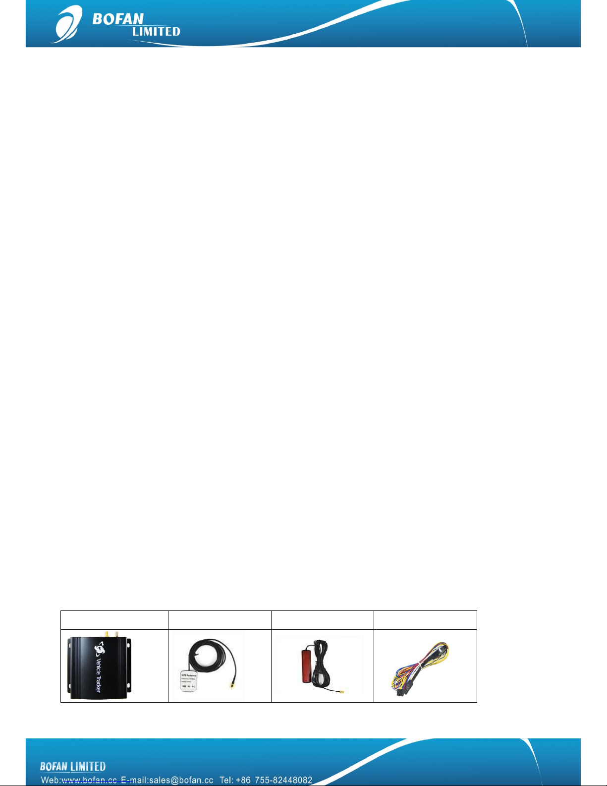
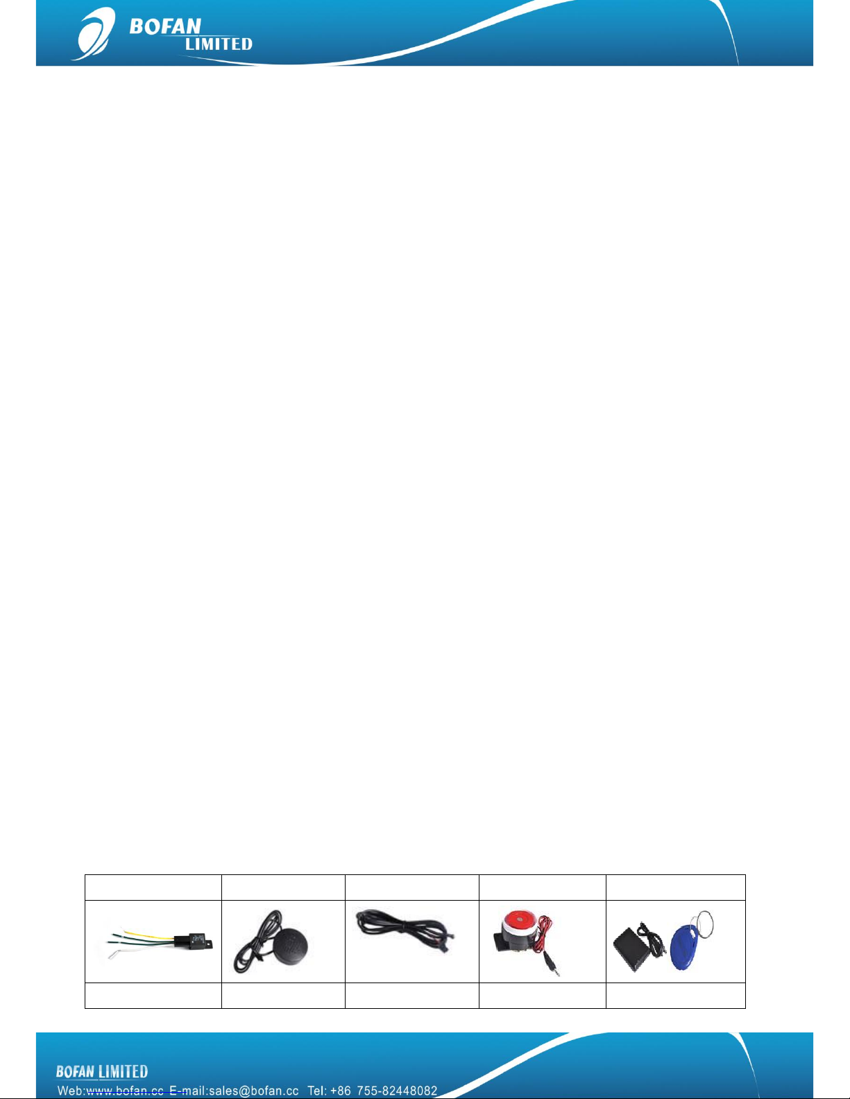
2.1 Standard Package
Main Unit
GPS Antenna
GSM Antenna
Plug-in power Wires
Page 5
3
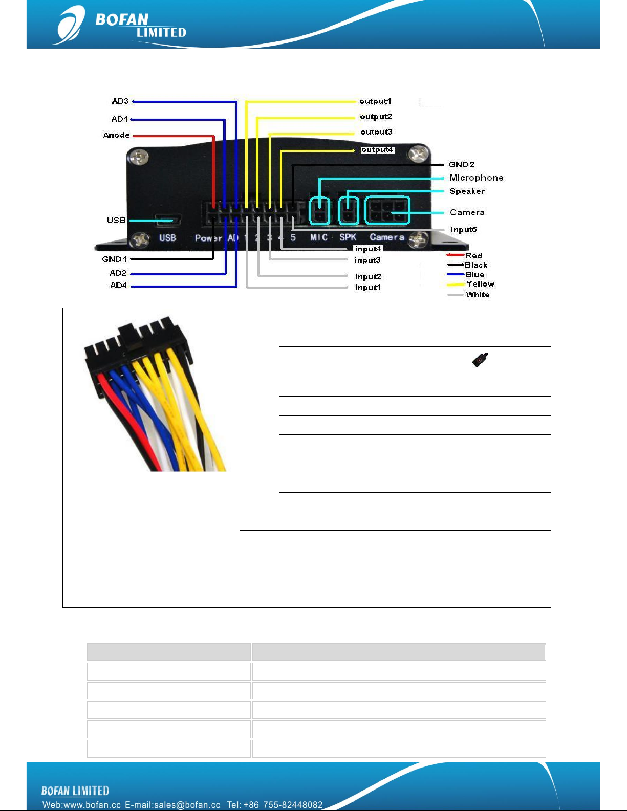
2.2 Basic Structure
Red
Anode
Ext. Power(+)
Black
GND1
Ext. Power(-) / GND
GND2
Be connected to SOS button
Blue
AD1
Can connect to fuel sensor
AD2
Can connect to temperature sensor
AD3
Can connect to alcohol sensor
AD4
Can connect to any other analog input sensor
Yellow
Output1
Can connect to relay
Output2
Can connect to buzzer
Output3/4
Can connect to any other OC output control
accessories
White
Input1
Be connected to SOS button
Input2/3
Low frequency electric effective
Input4
Must be connected to vehicle ignition
Input5
High frequency electric effective
2.3 Specification
Items
Specifications
Weight
0.23KG (only for main tracker, without accessories)
Dimensions
88(L)x 83(W) x 35(H) mm
Input Voltage
DC 9V~36V/1.5A
Back-up Battery
600mAh/3.7v
Power Consumption
50mA standby current
Page 6
4
Operating Temperature Range
-10°C to +60°C
Storage Temperature Range
-20°C to +70°C
Humidity
Up to 75% non-condensing
Back-up Battery work time
8~24 hours depends on preset report interval
GSM Frequency
GSM 850/900/1800/1900MHz
GPRS
Multi-slot Class 8(4Rx, 1Tx, 5 slot Max.)
Support all 4 coding schemes(CS-1, CS-2, CS-3 and CS-4)
·Maximum download speed is 85.6kbps
·Maximum upload speed is 21.4kbps
GPS Chip
SIRF III
GPS Sensitivity
-159dBm
GPS Channels
4 channels 20 parallel
Cold Start
35 sec
Warm Start
35 sec
Hot Start
1 sec
Positioning Accuracy
10meters at 2D RMS
GPS Antenna
External
GSM Antenna
External
LED
3 LED lights to show GPS,GSM and Power status
Memory
Save 15,000+ blind data
Motion sensor
YES
I/O
5 digital inputs,3 negative and 2 positive triggering;4 outputs
AD
4ch*12Bits
Certificates
CE, FCC, RoHS
2.4 Features
Manually tracking via SMS or automatically location update via SMS
Get Google Map link for current location by SMS request
Real-time online tracking in FMS platform via GPRS
Update position online via time interval, distance, angle, move ratio and ACC ratio
SOS alarm (available to preset 3 SOS number)
External power cut alarm and low battery alarm
Speed alarm, Geo-fence alarm, shake alarm,
Stop Vehicle remotely via relay (Stop Engine)
Engine On/Off alarm, engine on hours report
Position logging capacity up to 15,000+ waypoints if no GPRS signal
Take photo automatically at a preset time interval
Page 7

5
Take photo automatically when SOS or Geo-fence or any other alarm triggered
Update door open/close status, available to control open/close vehicle door by SMS or platform
Available to set different alarm notification ways, such as via SMS, call or email
Synchronous record vehicle mileage
Available to send mileage alarm to remind vehicle maintenance
Automatically stop vehicle or activate buzzer/siren when Geo-fence, speed alarm or any other alarm trigger
Support taking photo by extra camera (max 4pcs cameras), 6KB for each photo
Support voice monitoring and two way conversation via extra speaker and microphone
Support driver identification and students taking school bus management by extra RFID sets
Support fuel / temperature and alcohol sensor
I/O: 5 digital inputs, 3 negative and 2 positive triggering; 4 outputs.
Analog Input: 4*10bits resolution analog inputs
2.5 Application
This tracker can be used for fleet management, vehicle rental tracking, taxi management, transportation,
vehicle Insurance, and school bus etc. More details for each solution, please contact your sales representative.
3. Installation and Operation
Note:
When test tracker in office, please charge the tracker via 12V external power charger for 3 hours at
least before following below steps, once you connect the tracker power wire (red/black) to external
power supply wire directly, it is in charging.
The SIM card must support GPRS service, support calling and SMS service, can display caller’s ID.
It is a GSM card not CDMA card. And please disable the SIM card PIN code.
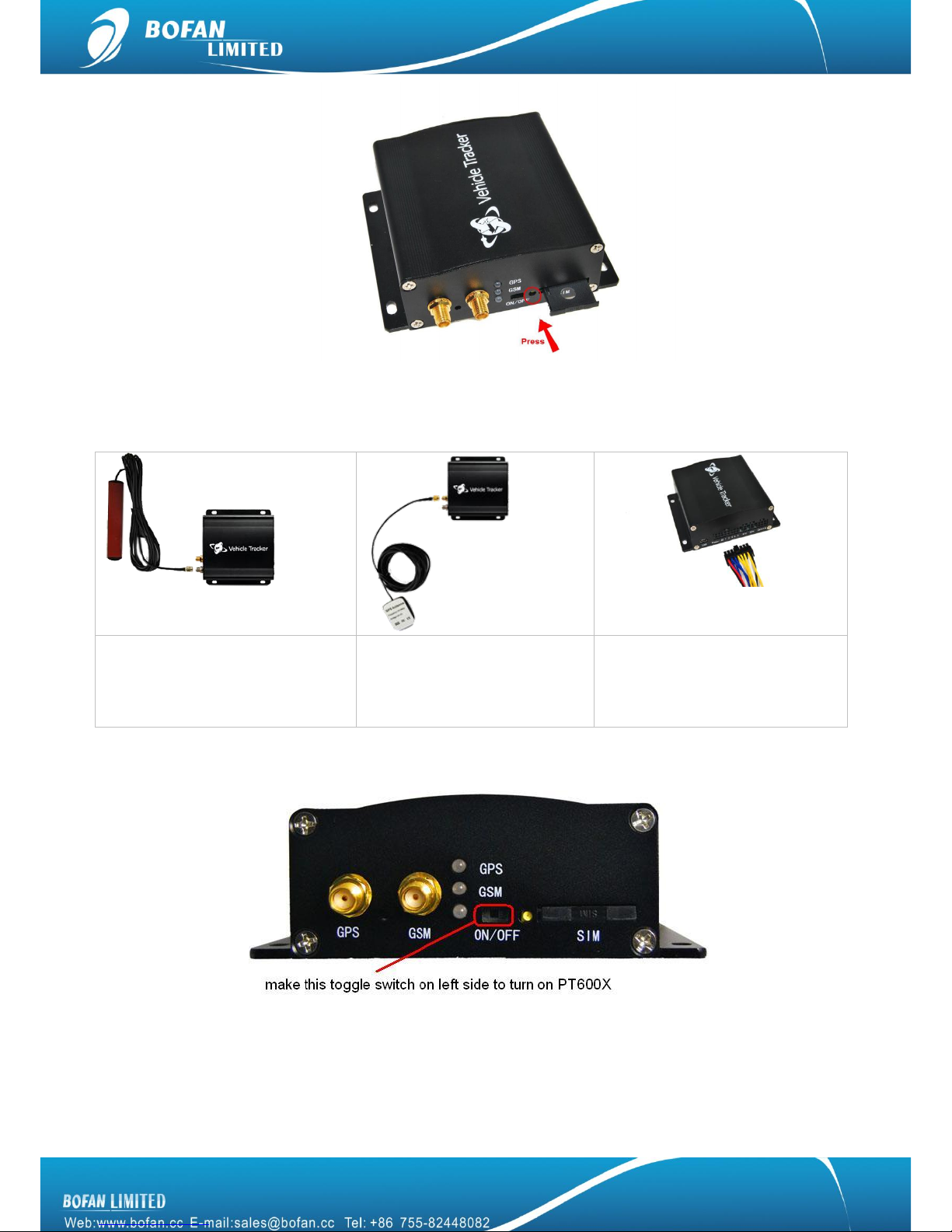
First step, install the SIM card
Press the yellow button to eject the SIM card Holder, Push it back after SIM card inserted.
Page 8
6
Second step, connection
Basic connection as the following table is NEEDED:
Connect the GSM Antenna
Connect the GPS Antenna, put
the GPS antenna black side
upside face the sky
Connect the wires to tracker, and
also connect red wire to vehicle
battery (+), black wire to vehicle
battery (-).
Third step, turn on the tracker
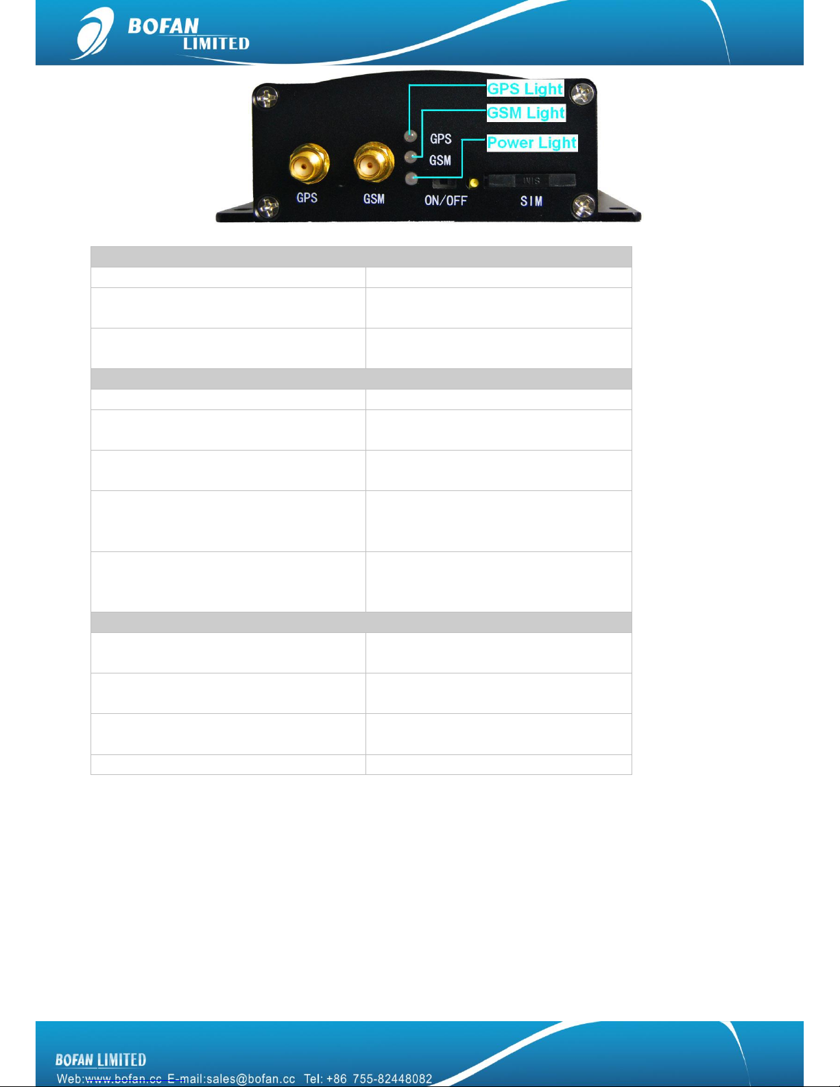
After turn on the tracker, please refer to the signal light functionality.
Page 9
7
GPS signal Light - indicating GPS signal status
RED light Flashing fast
The unit is being Initialized
RED light Flashing
( on for 2 seconds and off for 2 seconds)
Initialization succeed but GPS signal does
not fix
Green light Flashing
(on for 0.1 second and off for 2.9 seconds)
PT600X has GPS signal
GSM signal Light - indicating GSM signal status
RED light Flashing fast
The unit is being Initialized
RED light Flashing
( on for 2 seconds and off for 2 seconds)
Initialization succeed but GSM signal
does not fix
RED light Flashing
(on for 0.1 second and off for 2.9 seconds)
PT600X is connected to the GSM network
Green light Flashing
( on for 2 seconds and off for 2 seconds)
PT600X does not connect to server
successfully after making GPRS
communication settings
Green light Flashing
( on for 0.1 second and off for 2 seconds)
PT600X connects to server successfully
after making GPRS communication
settings
Power Light - indicating Power status
Green Light keep on bright
PT600X is connected with external power
source
Green Light keep on flashing
PT600X is not connected with external
power source but has sufficient power
Red Light keep on flashing
PT600X is not connected with external
power source and has no sufficient power
RED Light Flashing fast
No power, please charge immediately
4. Start Tracking
You can start to track your vehicle or test the tracker after GSM and GPS light work normally. There are two
ways to track the vehicle, one is by mobile and the other one is by FMS platform.
4.1 Tracking by mobile:
To get position by calling
1. Call the SIM card number in tracker from your mobile.
Page 10

8
2. Tracker will hang up automatically after several rings, then replies a position SMS to your mobile phone.
Note: if you don’t like the tracker reply a message after calling, you can send command 000000OPT0 to close
this function, if you want to restore this function later, you can send command 000000OPT1 to activate this
function again.
To get position by SMS command
Note: The tracker default password is 000000, if you already changed it, please use the new one in all SMS
command. Tracker only replies command from a user which uses the correct password. Commands with wrong
Password will be ignored.
Send SMS command to SIM card number in tracker from your mobile, command format: <password>RCP
For example: you edit the SMS command 000000RCP and send it, after a few seconds, you will get a SMS
reply similar with below contents:
Latitude = 22.5632 Longitude = 114.0940, Speed = 2.6854Km/h, Odometer = 10.98KM GPRS: OFF, EXPW: ON,
Time: 2010-12-07 08:47:45
Explanation:
GPRS means tracker connection FMS platform status
ON: means tracker connect FMS platform ok
OFF: means tracker connect FMS platform not ok
Fail: means tracker connect FMS platform fail
EXPW means external power connection status:
ON: means tracker already connect to external power
OFF: means tracker does not connect to external power
Note: when tracker doesn’t get GPS signal, it will reply a SMS starts with ―Last‖, which means this data is for
the last place where the tracker got GPS signal successfully.
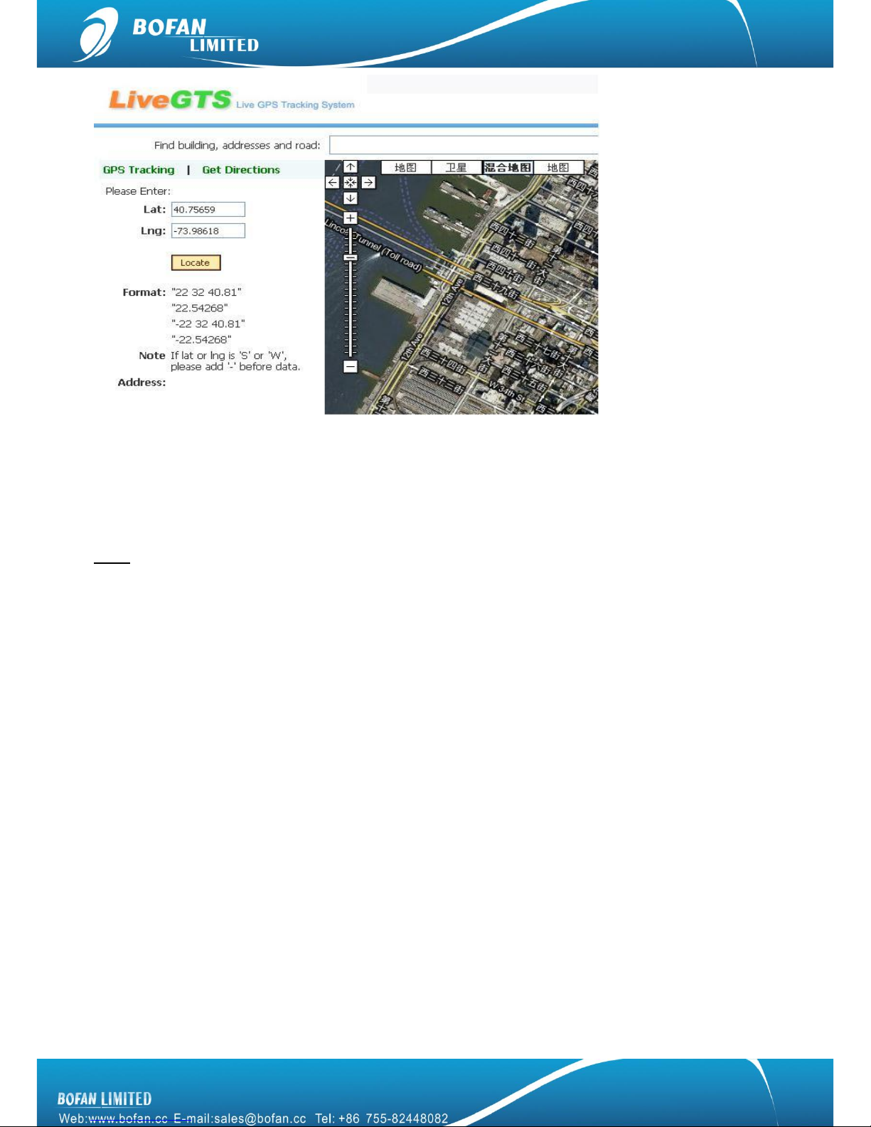
Above two methods just got coordinate for position, you can locate this position in your FMS or
http://demo.livegts.com which includes the Google map, manually input the latitude and longitude what you get
from this reply SMS and click the "Locate" button. It will display the place on map. Please refer to following
picture:
Page 11
9
To get position in Google Map link
Send SMS command to SIM card number in tracker from your mobile, command format: <password>RCM
For example: you edit the SMS command 000000RCM and send it, after a few seconds, you will get a SMS
reply with a position link, you can click this link directly and locate it on your mobile.
Note: it will cause GPRS cost for your mobile.
4.2 Tracking by FMS platform
Please ensure that your SIM card in PT600X supports GPRS connection.
If you want to do live tracking on platform, you need strictly to add new tracker, set tracker ID, tracker SIM card
APN, FMS server, tracker Port and time interval as below steps 4.2.1~4.2.5.
4.2.1 Add New Tracker in FMS
Login FMS: open your FMS website by IE and login with your account
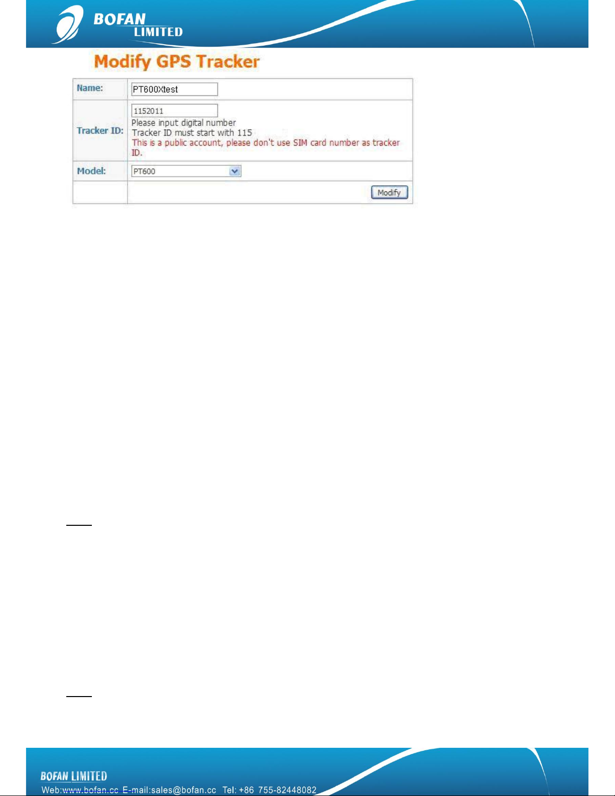
Go to ―Manage‖ -> ―Tracker Config‖ -> click ―Add New Tracker‖, please fill in name and tracker ID, select
correct tracker Model, and finally click ‖Modify‖ to add this tracker successfully.
Page 12
10
Name: can be any name for your tracker.
Tracker ID: Tracker ID can be any digit numbers, but must start with the fixed three numbers which display
in your FMS (here the tracker ID starts with 115 just for example), and total numbers should less than 10.
Model: must select the correct model number PT600. (No PT600X option, just select PT600.)
Please remember to click ― Modify‖ button after you input all information.
Now, please use your mobile to send below SMS commands to tracker and configure it to work with FMS
platform, after you do all below setting, you can get back to FMS real-time to monitor your tracker online.
4.2.2 Set Tracker ID by SMS
SMS Command format : <password>GID<ID>
Example: Sending SMS command 000000GID1152011 to set the tracker ID what you just added in FMS.
Tracker will reply with an SMS ―SET OK, ID=1152011‖.
Note: 1152011 just for example at here, please use your correct complete tracker ID what you added in your
FMS.
4.2.3 Set Tracker SIM card APN by SMS
SMS Command format : <password >APN<APN>, <User>, <Pass>
Example: Sending SMS command 000000APNCMNET to set the tracker SIM card APN.
PT600X will reply with an SMS ―SET OK, APN: CMNET, USER: PASS : ‖.
Note: CMNET is China mobile’s APN, no username & password for it. You can ask your GSM operator for their
SIM card GPRS connection APN, username and password, if it has user name and password; you just add the
user name and password after APN and use ―,‖ between each other, the complete command is
Page 13

11
000000APN<APN data>, <User name>, <Password>
4.2.4 Set FMS server and tracker port by SMS
SMS Command format : <password> SVR<FMS domain>, <Port>
Example: Sending SMS command 000000SVRDEMO.LIVEGTS.COM,8600 to set the FMS domain and tracker
port number.
PT600X will reply with an SMS ―SET OK, IP: DEMO.LIVEGTS.COM,8600‖.
Note: Please use your FMS complete domain name in capital in SVR command, DEMO.LIVEGTS.COM just for
example at here. PT600X’s port number always is 8600.
4.2.5 Set Time Interval by SMS
It is for automatically update tracker position in FMS
SMS Command format : <password>GTI<time seconds>
SMS Example: Sending SMS command 000000GTI30 to set the time interval.
PT600X will reply with a SMS ―Set GPRS Time Interval=30 OK‖.
Note:
If you want to save GPRS cost for SIM card in tracker
You can set the tracker using longer time interval when vehicle ignition is off. In this case, please connect
the PT600X’s input4 to vehicle ignition wire, and send SMS command 000000GTI30,0,0,0,240 to tracker,
and then PT600X will update position to FMS very 30 seconds when vehicle ignition is ON, and every 2
hours when vehicle ignition is OFF (30seconds x 240=7200seconds=2hours).
If your vehicle often runs on the curve road, for get better route display in FMS
You can set the tracker update position at each corner, the complete command for better route and saving
GPRS cost is 000000GTI30,0,30,0,240 to tracker, you also need to connect the PT600X’s input4 to vehicle
ignition wire, the tracker will update position to FMS once the vehicle turns bend for 30 degree or over 30
degree, and also update position very 30 seconds when vehicle ignition is ON, every 2 hours when vehicle
ignition is OFF (30secondsx240=7200seconds=2hours).
Note: Refer above 4.2.2 ~ 4.2.5 steps commands, also can be set via debug tool on your PC, please refer to
―BOFAN Device Online Configuration User Manual‖
Page 14
12
After done all above settings, please login your FMS to track it online now.
If it still show ―NO DATA‖ in FMS after few minutes, please send below four SMS commands to tracker for
confirming tracker’s setting:
1st command: 000000ASKGID
Tracker will reply you ―Query Parameter OK, GIDXXXXX‖, please check if it is the correct tracker ID
number what you added in FMS, if no, please send new command 0000000GID with correct ID number
again.
2nd command: 000000ASKAPN
Tracker will reply you ―Query Parameter OK, APNXXXXX‖, please check if it is the correct APN of your SIM
card in tracker, if no, please send new command 000000APN with correct APN contents again.
3rd command: 000000ASKSVR
Tracker will reply you ―Query Parameter OK, SVRXXXXX,XXXX‖, please check if it is the correct FMS
domain and tracker port number, if no, please send new command 000000SVR with correct FMS domain
and 8600 contents again.
4th command: 000000ASKGTI
Tracker will reply you ―Query Parameter OK, GTIXX‖, please check if it is 0, you need to send new
command 000000GTI30 again.
If you still need to get help from us, please kindly send your FMS login access and tracker’s full response of
above four SMS commands and 000000RCP to us by email.
5. Accessories
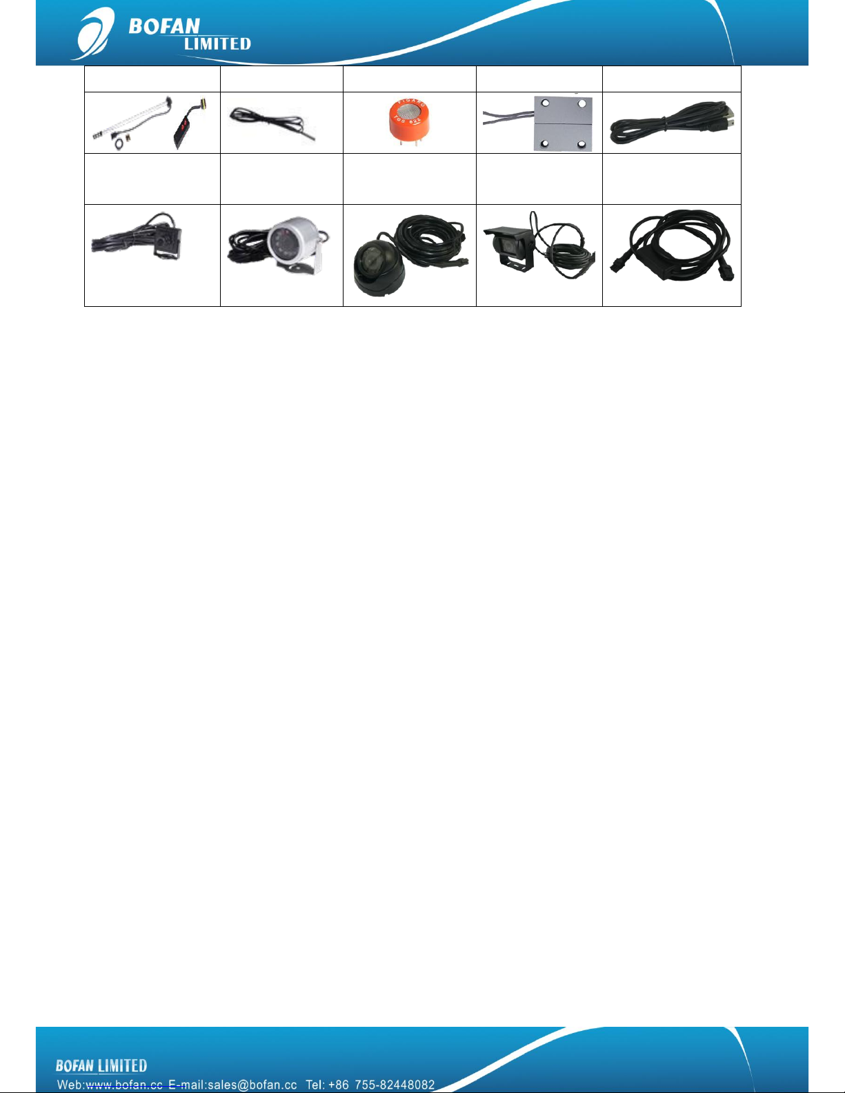
5.1 Optional accessories
Relay (12V & 24V)
Speaker
Microphone
Buzzer
RFID Sets
Fuel Sensor Sets
Temperature
Alcohol Sensor
Wired Door
USB PL2303
Page 15
13
Sensor
Sensor
Normal Camera
Circular Camera
(Infrared)
Conch Camera
(Infrared)
Rectangular
Camera (Infrared)
Camera Conversion
Cable
5.2 Accessories connection
Microphone: plug-in tracker interface where marked MIC
Speaker: plug-in tracker interface where marked SPK
Normal camera: plug-in tracker interface where marked Camera
Circular camera: plug-in tracker interface where marked Camera
Conch and Rectangular camera: Connect ―camera conversion cable‖ to tracker interface where
marked Camera.
Buzzer: red wire of buzzer connect to tracker’s red wire for power supply directly, black wire of buzzer
connect to tracker’s output2
Door sensor: one wire of door sensor connect to tracker black wire, the other wire of door sensor
connect to tracker input2
RFID sets: using the RFID USB cable connect it between tracker and RFID reader, tracker must get
external power supply when using RFID sets.
Fuel sensor: it should be connected to AD1, please refer to fuel sensor user manual for more details
Temperature sensor: if you bought temperature sensor, it already be connected to AD2
Alcohol sensor: if you bought alcohol sensor, it already be connected to AD3
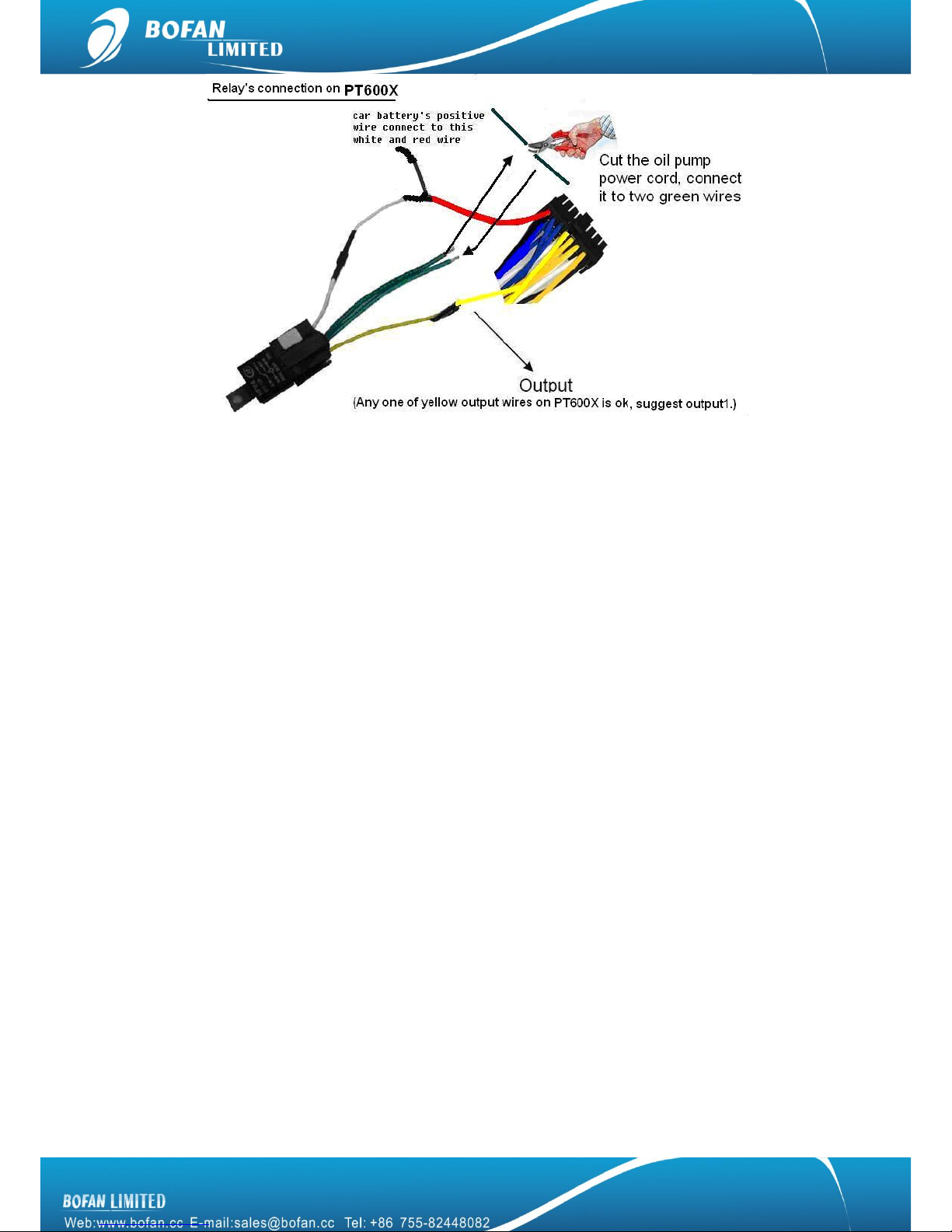
Relay: as below picture, suggest connect to output1
Page 16
14
5.3 Accessories operation
SOS: sending SMS command 000000SOS,13112374567 to set phone number for receiving SOS
alarm by SMS and call. Once you press the SOS button (black button in plug-in wires), will get SOS
alarm on phone 13112374567.
Microphone: Voice monitoring
Sending SMS command 000000TEN to tracker, tracker will call you back soon, and then you can
hear the voice around the microphone in vehicle.
Sending SMS command 000000TEM1 to tracker, you can call the tracker SIM card number directly
to enter voice monitoring mode and listen the voice around the microphone in vehicle. But this voice
monitoring mode will close after hung the call.
Sending SMS command 000000TEM3 to tracker, it activate the voice monitoring mode, any phone
can call the SIM card number in tracker to enter voice monitoring mode at any time, it never close
until you send above two commands to change it.
Speaker: Two-way communication; must connect microphone too.
Sending SMS command 000000TEL to tracker, tracker will call you back soon, and then you can
talk to driver.
Sending SMS command 000000TEM2 to tracker, you can call the tracker SIM card number directly
to enter two-way communication mode and talk to driver. But this two-way communication mode will
close after hung the call.
Sending SMS command 000000TEM4 to tracker, it activate the two-way communication mode, any
phone can call the SIM card number in tracker to enter two-way communication mode at any time, it
never close until you send above two commands to change it.
Page 17

15
Single Camera: tracker must working in FMS very well
Sending command 000000PHO to tracker to take one picture, the picture will be transferred to FMS
and display in real-time and photo report page.
Sending command 000000PTI300 to tracker for setting tracker automatically take picture each 300
seconds, the picture will be transferred to FMS and display in real-time and photo report page.
Click ―take photo‖ button in real-time page in FMS to take one picture, you will see it in real-time and
photo report page.
Multiple Cameras: each camera with one ID, they will work in sequence, each camera takes 2
minutes to take photo and transfer it to FMS.
Sending command 000000PHO1 to tracker to take one picture by No.1 camera, the picture will be
transferred to FMS and display in real-time and photo report page.
Sending command 000000PHO to tracker to take one picture by each camera, the picture will be
transferred to FMS and display in real-time and photo report page.
Sending command 000000PTI720 to tracker for setting tracker automatically take picture by each
camera each 12 minutes, the picture will be transferred to FMS and display in real-time and photo
report page. More cameras you connected, more minutes request in this command.
Click ―take photo‖ button in real-time page in FMS to take one picture by each camera, you will see it
in real-time and photo report page.
Relay: stop vehicle remotely
Sending SMS command 000000OPC1,1 to tracker, vehicle will be stopped immediately.
Sending SMS command 000000OPC1,1,1 to tracker, vehicle only be stopped after its speed lower
than 20km/h.
Sending SMS command 000000OPC1,0 to tracker to restore the vehicle before you driving it.
Click ―Stop Engine‖ button in real-time in FMS, select tracker, select output1, choose ―Yes‖ after
―Safe Mode‖, select ―Stop Engine‖ after ―Action, finally click ―Submit to tracker‖, when you want to
restore it, just select ―Restore Engine‖ after ―Action‖, safe mode can be ignored when restore
engine.
Please don’t use this feature while car/vehicle with high-speed driving, and we suggest connect relay with
fuel control line in your car, Bofan is not liable for any traffic accidents.
Buzzer:
Sending SMS command 000000OPC2,1 to tracker to trigger buzzer for one time
It also can be set to automatically triggered by other alarms
For example, Speed Alarm Buzzer keep working for 10 seconds,
Page 18
16
First you need to set Speed Alarm (both are ok by SMS or in FMS)
Second sending two SMS commands 000000AN1'#OPC2,1,',10,'#OPC2,0' and
000000SALSPD10001 to tracker.
Note: the fifth parameter in SALSPD is for the AN command number, AN1 1 at fifth parameter, AN2 2
at fifth parameter, parameter 1st to 4th details, please refer to command list.
Wired Door Sensor: once two parts away from each other, it will send you key2 alarm, you can
rename this key2alarm to ―door open alarm‖ in system config in FMS.
RFID sets: it can be used for driver identification and students & school bus management, more
details please refer to RFID user manual.
About Fuel Sensor, Temperature Sensor and Alcohol Sensor operation details, please refer to its
own separate user manual.
6. SMS Commands List
Note: the device password is 000000 as default
Get tracker firmware version
Command
<password>VER
Remarks
VER=Version
Get current location
Command
<password>RCP
Remarks
Get current location’s latitude and longitude of PT600X
Two-way communication
Command
<password>TEL
Remarks
PT600X SIM card will call your mobile phone after you send the command, once you answer the
phone, two way communication begins
NOTE
Please install speaker and microphone on PT600X before using this function
Extending use of two-way communication
Command
<password>TEM2
Remarks
If you want to save credit of SIM card number in PT600X, you can send this command, then dial out
from your mobile phone to PT600X’s SIM card number for two way communication
Voice Monitoring
Command
<password>TEN
Remarks
PT600X SIM card will call your mobile after you send the command to PT600X, you can answer
this call and start to listen the voice around microphone
NOTE
Please install microphone on PT600X before you use this function
Extending use of Voice Monitoring
Page 19
17
Command
<password>TEM1
Remarks
If you want to save credit of SIM card number in PT600X, you can send this command to PT600,
later call PT600X’s SIM card number from your phone to monitor voice
Get Google map link by SMS request
Command
<password>RCM
Remarks
This command is still valid even don’t configure PT600X’s GPRS connecting
Change password
Command
<password>PWD<new password>
Remarks
PWD=Password (must be 6 digits)
Reset password when the previous password is forgotten
Command
000000RPW<new password>
Remarks
Please long press the SOS button when you send this command to PT600X
(new password must be 6 digits)
Set preset phone number for SOS button
Command
<password>SOS,<SOSNumber1>,<SOSNumber2>,<SOSNumber3>
Remarks
SOS Number: Preset phone number to receive phone call or SMS from PT600X. Max 16
digits. Maximum 3 SOS numbers can be set.
If only set the 1st number, PT600X will send SMS and then call to this first number after
pressing SOS button.
If set the 2nd or 3rd numbers too, PT600X will send SMS to all 3 numbers, only call to the 1st
number after press SOS button.
Note: <password>SOS, command is for cancel all pre set numbers.
Set Over Speed Alert
Command
<password>SPD<Max Speed>
Remarks
Max Speed (the preset speed value)
=0 to turn off this function
=[0,500](unit: Km/h)
Example: 000000SPD80 it will send alert when it is over 80Km/h
NOTE
When car speed is higher than the preset value, PT600X will send an alert SMS to the preset SOS
number.
Set Geo-fence Alert
Command
<password>GOF<Type>,<SWLat>,<SWLng>,<NELat>,<NELng>
Remarks
Type =1, alert when out of range
Type=2, alert when enter this range
SW=South-West
NE=North-East
Example:000000GOF0, to turn off this function
NOTE
When car leaves out or enters a preset scope, PT600X will send one Geo-fence SMS to the preset
SOS number.
Set Mileage Alert
Command
<password>MLA<base mileage>,<increment>
NOTE
This Mileage Alert can be sent to your mobile by SMS if you set your mobile number as SOS
number into this tracker installed in car and it also can be sent to your email address if you set your
email address in software successfully.
Example
000000MLA100000,50000
This example means, if the tracker records the car driving more than 10000km, tracker will send
Page 20
18
one Mileage Alert for each 5000km mileage increments.
Set Odometer
Command
<password>SOD
Remarks
unit: 100 meters
Example
000000SOD or 000000SOD0: it is to set the tracker’s odometer to be ―0‖
000000SOD100: it is to set the tracker’s odometer to be 10km. (100*100meter=10000m=10km)
000000SOD5000: it is to set the tracker’s odometer to be 500km.(5000*100=500000m=500km)
Set time zone for tracker
Command
<password>TMZ<Time>
Remarks
Time from -13 to 13
Example
000000TMZ8 for set China time zone
NOTE
After setting time zone into tracker, you can get your local time in tracker reply message.
Restart
Command
<password>RST<Type>
Remarks
Type=0 or null, to reboot PT600X
Type=1 to reboot GPS
Type=2 to reboot GSM
Reset PT600X to default
Command
<password>DFT
Remarks
DFT=Default
Request Power
Command
<password>RPO
Remarks
RPO=Request Power Voltage
Cut Power Alarm
Command
<password>CPA<Value>
Remarks
Value=0 to disable Cut Power Alarm
Value=1 to enable Cut Power Alarm
Default set: 000000CPA1
Get IMEI
Command
<password>IME
Remarks
To get tracker’s IMEI number
Note: IMEI number can’t be tracker ID number.
Output Control
Command
<password>OPC<Index>,<Action>
Remarks
Index
=1 means Out1
=2 means Out2
=3 means Out3
=4 means Out4
Action
=0 to close the output
=1 to open the output
Take photo at a preset time interval
Command
<password>PTI<time interval>
Page 21
19
Remarks
Time Interval =0 to turn off this function
Time Interval =[120-65535] (unit: second)
Example: 000000PTI300, PT600X will take photos every 300 seconds
NOTE
This feature is valid when PT600X’s firmware version is 1.40 above
Set Alarm Action
Command
<password>AN<Index1>’#<Index2>,’,<Index3>,’#<Index4>’
Remarks
Index1= 1 mean NO.1 Action. (it can be 1-5)
Index2=OPC2,1 means trigger output 2 on
OPC3,1 means trigger output 3 on
TEL13112345678 means trigger this TEL command to call 13112345678
NOTE: any other command can be used at index2
Index3=Time (Unit: second)
NOTE: If you want to automatically close the above alarm or trigger another alarm in few
seconds, please input the time at index3, and also set below index4.
Index4=OPC2,0 means close output 2
OPC3,0 means close output 3
TEL13012345678 means trigger this TEL command to call 13012345678
NOTE: Any other command can be used at index4
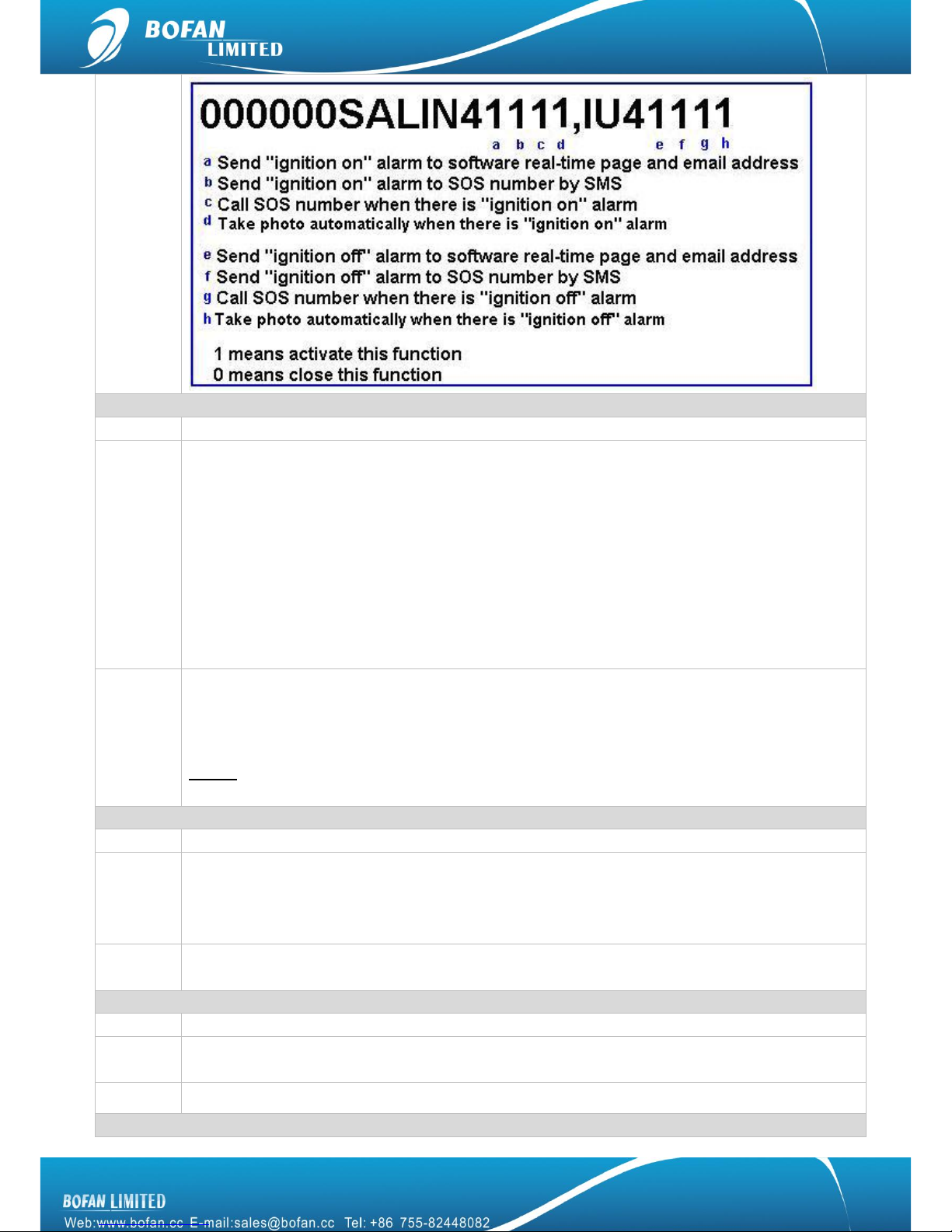
Set Alarm
Command
<password>SAL<Alarm type><Index1><Index2><Index3><Index4><Index5>
Remarks
Alarm type =IN1/IN2/IN/IN4/IN5/SPD/GEO/MLA/SKA/LPA/IU1/IU2/IU3/IU4/IU5
Index1=1, to alert on platform
=0, do not alert on platform
Index2=1, to send alert SMS
=0, do not send alert SMS
Index3=1, to call the preset SOS phone number
=0, do not call the preset SOS phone number
Index4=1, to take photo
=0, do not take photo
Index5=Action No.
you set in Index1 in above AN command
Default Setting:
000000SALIN11110
000000SALIN21110
000000SALIN31110
000000SALIN40000
000000SALIN50000
Example
000000SALIN11110
That means, when input 1(SOS key) is pressed, PT600X will send SOS alarm on platform, send
alarm SMS to SOS number, call to SOS number, but do not take photo
Page 22
20
AD alarm
Command
<password>AD<index1><index2><Parameter>,<alarm name>,<index3>
Remarks
Index1 =1—4 means AD1—AD4
Index 2 =[</>]
Parameter=[0~100] (unit: %)
Alarm name = default is AD1 alarm, if you use ―fuel alarm‖ at here, you will get alarm fuel alarm
SMS contents.
Index3 = 1 means input1
2 means input2
3 means input3
4 means input4
5 means input5
Example
000000AD1<10,Fuel Low,4
After you connect fuel sensor to PT600X AD1 wire, PT600X will send Fuel Low alarm SMS to SOS
number when tracker get AD1 data <10%, but this alarm is effective only when input4 on (if you
connect input4 to car ignition, then it means car ignition on).
NOTE: if your fuel sensor keep working even when car ignition off, you don’t need to set index3 as
input4 here.
Set Analog Voltage
Command
<password>AV<AD Port><min voltage of sensor>,<max voltage of sensor>,24
Remarks
AD Port=1—4 means AD1—AD4
Min voltage of sensor=input your sensor min voltage at here
Max voltage of sensor=input your sensor max voltage at here, it can’t be over the max voltage of
tracker support.
NOTE
If your analog sensor max voltage is not 6V, then you need to do this setting, to let tracker know
what is your sensor voltage specification
Shake Alarm(or Move Alarm)
Command
<password>SKA<index>
Remarks
Index = 1, to send shake alarm SMS to SOS number when PT600X shakes
= 0, not to send shake alarm SMS to SOS number when PT600X shakes.
NOTE
PT600X with built-in motion sensor to support this function.
Define motion sensor sensitivity
Page 23
21
Command
<password>MSS<value>
Remarks
Value= number range is 1-15. Default set: 000000MSS3(The larger value, the lower sensitivity).
Set char for alert SMS contents
Command
<password>ACH<Alarm><Char>
Remarks
ACH=Alarm Char
Alarm=IN1/IN2/IN3/IN4/IN5/SPD/GEO/MLA/SKA, etc.
Clear Saved data
Command
<password>CSV
Remarks
CSV=Clear Saved data
Check previous command setting
Command
<password>ASK<Command>
Example
000000ASKSVR, to check the server & port what you set at before
000000ASKGID, to check the tracker ID what you set at before
Set ID
Command
<password>GID<ID>
Remarks
Tracker ID can’t exceed 10 digit
Set APN
Command
<password >APN<APN>,<Username>,<Password>
Remarks
If your APN doesn’t have username and password, type APN only;
(Please get the correct APN of SIM card in tracker from your SIM card provider)
Set Server
Command
<password>SVR<domain>,<Port>
Remarks
Domain: the tracking platform domain name
Port: 8600, fixed for PT600X
Set Time Interval
Command
<password>GTI<Time Interval>,<Distant Interval>, <Angle>,<Move Ratio>,<ACC Ratio>
Remarks
Time Interval =[5-65535] (unit: second); 0,to turn off this function
Distant Interval =[100-65535],(unit: meter, suggest Distant Interval >500); 0, to turn off this
function
Angle= [15-360], (unit: degree, suggest Angle > 30 ); 0, to turn off this function
Move Ratio≧1 only integer; 0, to turn off this function
ACC Ratio≧1 only integer; 0, to turn off this function
NOT suggest use all Distant Interval and Angle and Move Ratio and ACC Ratio if you don’t have
special needs.
Page 24
22
7. Trouble Shooting
Problem: Device can’t power on
Possible Cause:
Resolution:
Wiring was not connected properly
Check if wiring connection is in order.
Battery needs charging
Recharge battery
Problem: Device doesn’t respond to SMS
Possible Cause:
Resolution:
GSM antenna was not installed properly
Make PT600X in good GSM network coverage.
Low power
Connect power cable to car battery directly or
use 12V charger to charge it for 3hours at least
GSM Network is slow
Wait for SMS. Sometimes GSM network slows
down during peak time or base has problem.
Wrong password in your SMS or wrong
SMS format
Write correct password or SMS format
The SIM in PT600X runs out of credit
Recharge credit of the SIM card
No SIM card
Insert working SIM card. Check in phone that the
SIM can send SMS message.
SIM card has expired
Check in phone if the SIM card can send SMS
message. Replace SIM card if need.
SIM has PIN code set
Remove PIN code by inserting SIM card in your
phone and deleting the code.
SIM is warped or damaged
Inspect SIM card, clean the contacts. If
re-installing does not help, try another to check
Roaming not enabled
If you are in another country, your SIM card must
have roaming service enabled.
Problem: Reply SMS starts with ‘Last…’
Possible Cause:
Resolution:
PT600X does not have clear view of the sky
Move the antenna of the unit to a location where
the sky is visible.
PT600X is indoor
Make it work in an open area outside
Battery power is low
Recharge device
Problem: Can’t real-time tracking on platform
Possible Cause:
Resolution:
GPRS setting is not correct.
Please set each step strictly according to user
manual.
APN is wrong
Ask your GSM provider for the correct APN,
username and password if it has, then set again.
Tracker ID set by SMS command is not
same as that one added in FMS
Check if the trackers ID you set into tracker is
same exactly as the one you write in FMS.
If your problem still can not be solved by above resolution, please using debug tool to read tracker log, and
send log to us for further analyze. For using debug to read tracker log, please refer to ―Debug Read Tracker
Log‖ user manual.
 Loading...