

Page 1
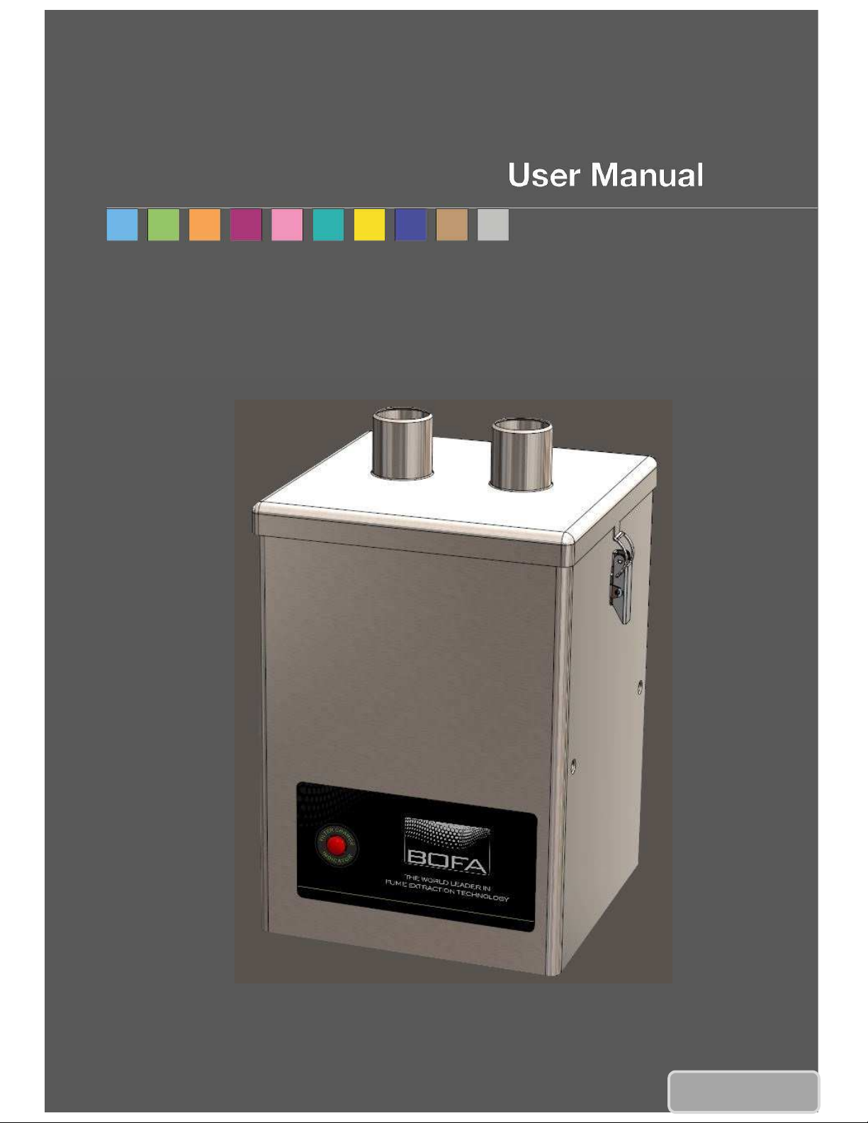
V250
V1 Feb 15
Page 2
Page 3
Overview
01
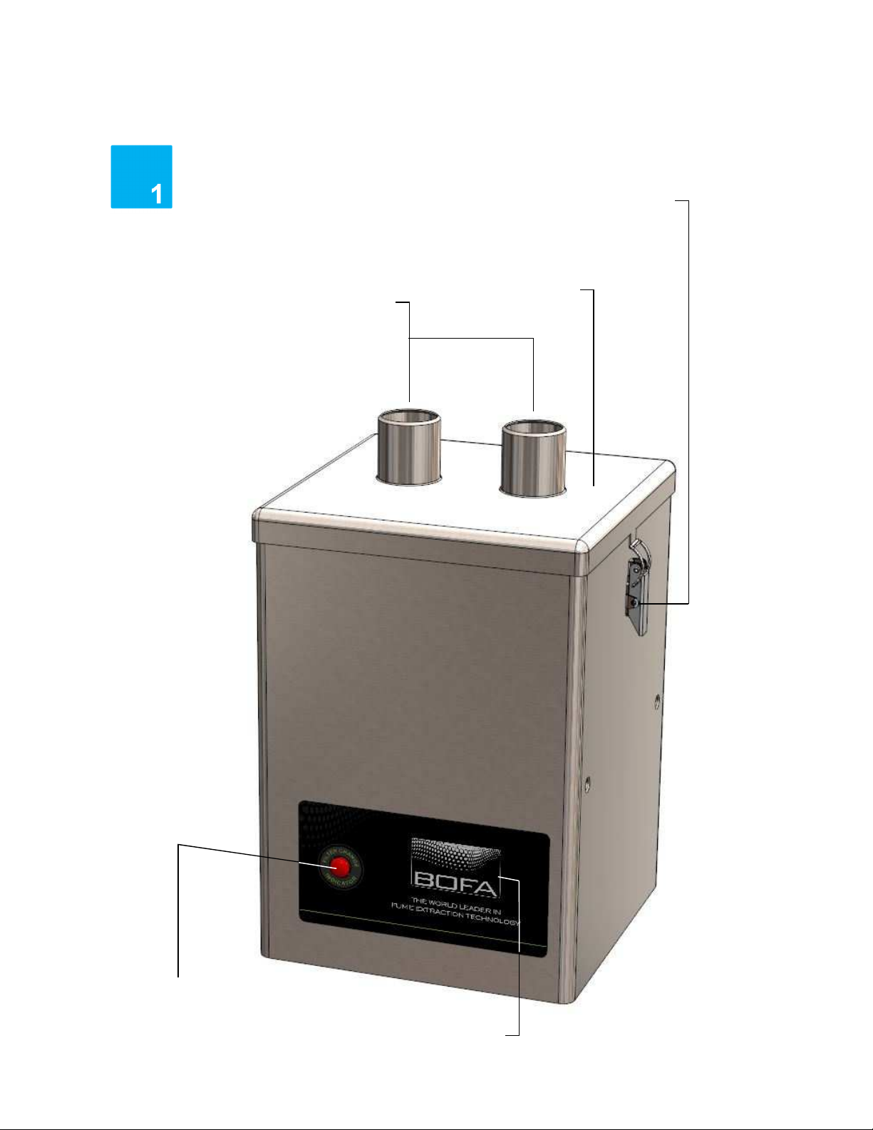
Lid
Clips
Air Inlets
Filter Condition
Light
Company Branding
Page 4
Overview
02
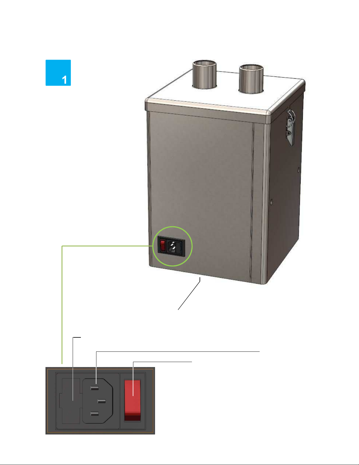
Air Outlet/Motor
Fuse Compartment
Cooling
Main Isolation
Switch
Mains Inlet
Page 5
Safety Instructions
01
Important
To reduce the risk of fire, electric shock or injury:
Important safety notes
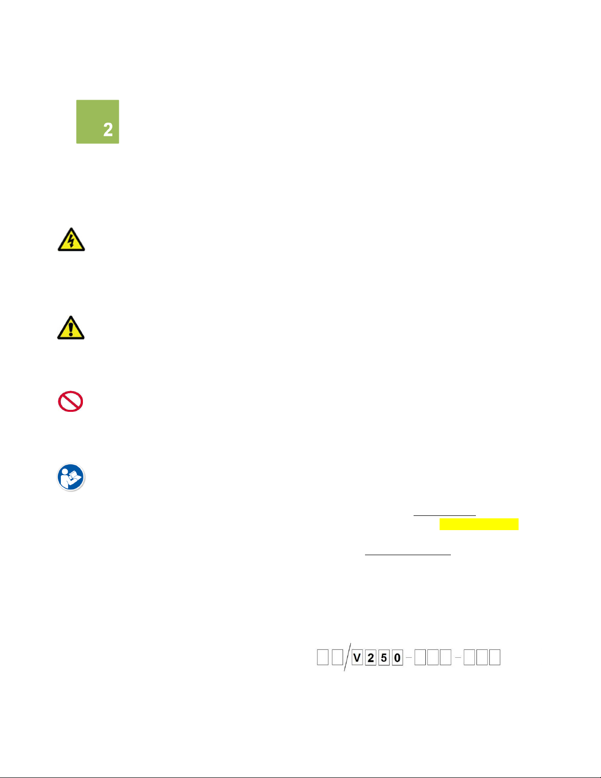
Concerning symbols used on the extraction unit and referred
to within this manual.
Danger
Refers to an immediately impending danger. If the danger is
not avoided, it could result in death or severe (crippling)
injury. Please consult the manual when this symbol is
displayed.
Warning
Refers to a possibly dangerous situation. If not avoided it
could result in death or severe injury. Please consult the
manual when this symbol is displayed.
Caution
Refers to a possibly harmful situation. If not avoided,
damage could be caused to the product or something in its
environment.
Important (Refer to manual)
Refers to handling tip and other particularly useful
information. This does not signify a dangerous or harmful
situation. Refer to manual when this symbol is displayed.
Electrical Safety
The V250 has been designed to meet the safety
requirements of the Low Voltage Directive 2006/95/EC
(previously numbered 73/23/EEC)
Warning
When working with the pump/motor housing open, Live
230/115 volt mains components are accessible. Ensure that
the rules and regulations for work on live components are
always observed.
1. Always isolate the system from the mains power
supply before removing the pump/motor access
panel.
2. Use only as described in this manual.
3. Connect the system to a properly grounded outlet.
Dangers to eyes, breathing and skin
Once used, the filter within the V250 system may contain a
mixture of particulates, some of which may be sub-micron
size. When the used filters are moved it may agitate some of
this particulate, which could get into the breathing zone and
eyes of the operative. Additionally, depending on the
materials being used, the particulate may be an irritant to
the skin.
This unit should not be used on processes with sparks of
flammable materials or with explosive dusts and gases,
without implementation of additional precautions.
Caution: When changing used filters always wear a mask,
safety shoes, goggles and gloves.
Carbon selection
Please note that the media within the filter fitted in the
V250 is capable of adsorbing a wide range of organic
compounds. However, it is the responsibility of the user to
ensure it is suitable for the particular application it is being
used on.
BOFA Technical Service
If problems arises with your V250 unit please contact us:
• Visit our website at www.bofa.co.uk for on-line help.
• Or contact the helpline on +44 (0) 1202 699444,
Mon-Fri, 9am-5pm.
Email: [email protected]
Serial Number
For future reference, fill in your system details in the space
provided. The serial number is on the rating label located on
the side/rear of the unit.
Serial Number:
Page 6
Safety Instructions
02
02
Warning and Information labels
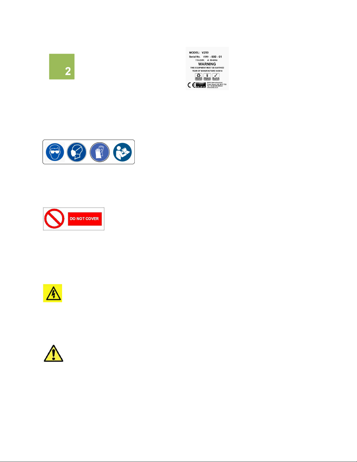
The following listing details labels used on your V250
extraction unit.
Goggles, Gloves & Mask Label
Location: Front face of filter.
Meaning: Goggles, Gloves and Masks should be worn while
handling used filters.
Do Not Cover Label
Location: Bottom panel.
Meaning: Do not cover any louvers or holes adjacent to the
label.
Electrical Danger
Location: Bottom Panel
Meaning: Removal of panels with this label attached will
allow access to potentially live components.
Warning Label
Serial Number Label
Location: Next to mains inlet.
Meaning: This label contains a variety of information about
the extraction unit, including.
• Company name, Address & Contact number
• Extractor model
• Unit serial number
• Operating voltage range
• Maximum current load
• Operating frequency
• Year of Manufacture
• Relevant approval markings/ logos
PLEASE NOTE: If the equipment is used in a manner not
specified by the manufacturer, the protection provided by
the equipment maybe compromised.
Fire Risk Warning
In the very rare event that a burning ember or spark is
drawn into the fume extraction unit, it may be possible that
the filters will ignite.
Whilst any resultant fire would typically be retained within
the fume extraction unit, the damage to the extractor
be significant. It is therefore essential to minimise the
possibility of this occurring by undertaking an appropriate
Risk assessment to determine:-
a). Whether additional fire protection equipment should be
installed.
b). Appropriate maintenance procedures to prevent the risk
of build-up of debris which could potentially combust.
could
Location: Next to release clips.
Meaning: Power should be isolated before the panel with
this label attached is opened/ removed.
This unit should not be used on processes where sparks
could occur, with explosive dusts and gases, or with
particulates which can be pyrophoric (can spontaneously
ignite), without implementation of additional precautions
It is essential that nozzles or other extraction/ fume capture
devices and hoses/pipework are cleaned regularly to prevent
the build-up of potentially ignitable debris
Page 7
Before installation
01
Packaging Removal & Unit Placement
Before installation, check the extraction unit for damage.
All packaging must be removed before the unit is connected
to the power supply.
Please read all instructions in this manual before using
this extractor.
1. Move the unit to the location where it is going to be
installed and remove the outer packaging. This unit should
be installed in a well-ventilated area.
Ensure that 500 mm space is available around any vented
panels on the extractor to ensure adequate airflow.
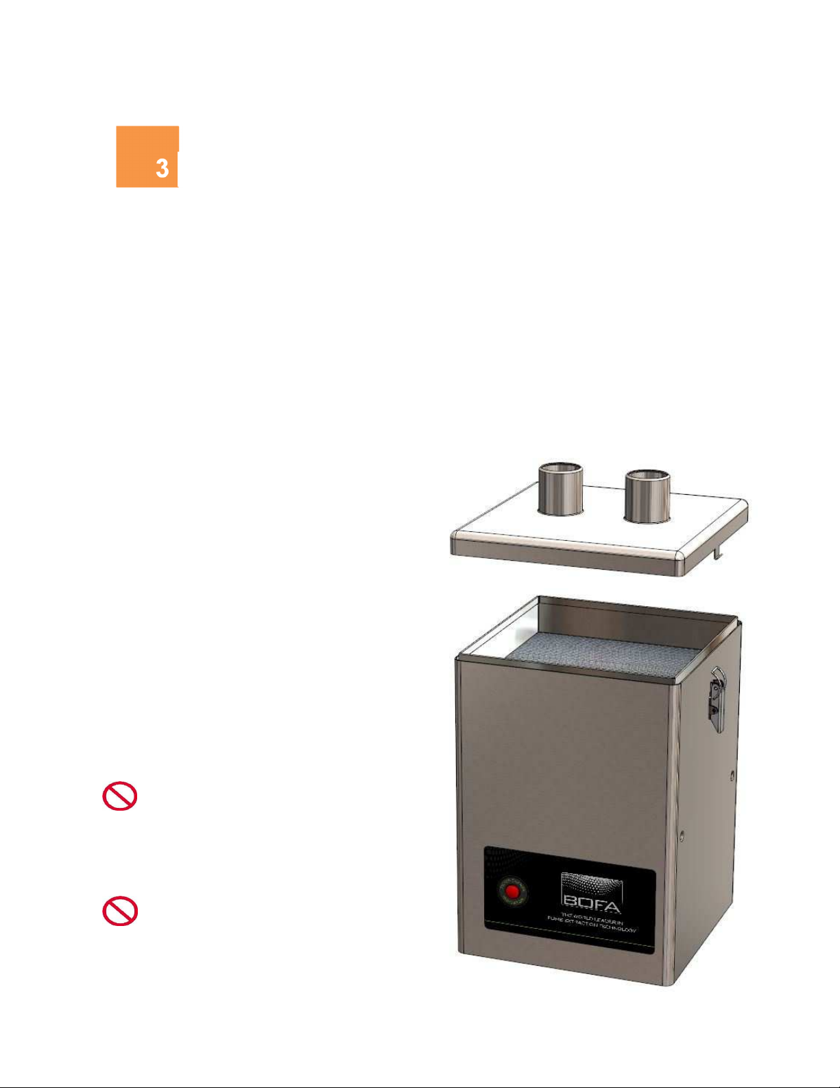
2. Check the filter is located in its correct position before
replacing the lid and securing the clips
Caution
Do not block or cover the airflow and motor
cooling ports on the unit, as this severely restricts airflow
and may cause damage to the unit.
Caution
Under no circumstances should the exhaust
outlet/s be covered as this will restrict the airflow and cause
overheating.
Page 8

Installation
01
Specification V250
Dimensions: Height 380mm Depth 260mm Width 260mm
Weight: 10kg (22lbs)
Voltage: 115-230V
Frequency: 50/60Hz
Full load current: 230V:1A 115V: 1.2A
Power: 140w
Capacity: 180m³h (106CFM)
Connection to Power Supply
Please follow the above specification when selecting the
power supply outlet for the extraction system, ensure the
power supply is suitable before connecting the V250
system.
Check the Integrity of the electrical power cable, if the
supply cord is damaged the extraction unit should not be
connected to the mains. The supply cord should only be
replaced by a BOFA engineer as an electrical safety test may
be required after replacement.
The extraction unit MUST be connected to a
properly earthed outlet.
If your extraction system was ordered with any
optional extras please read section 4.03 before
the power connection is made as additional connections
may be required before power is connected to the
extractor.
Connect the power cable to an isolated electrical supply.
The mains socket should be installed near the extractor it
should be easily accessible and able to be switched On/ Off.
The cable run should be arranged so as not to create a trip
hazard.
Page 9
Operation
01
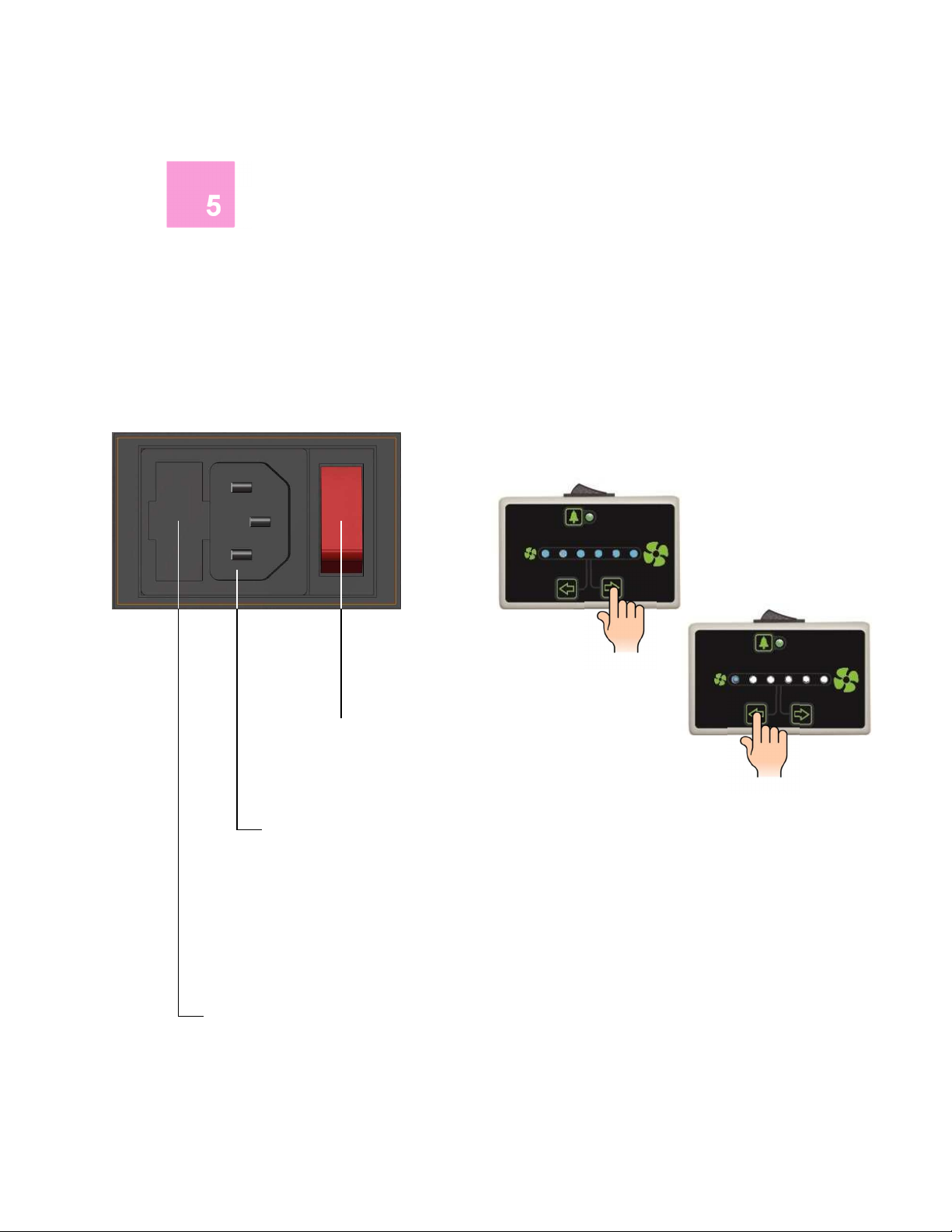
Fuse Compartment
Turning extraction unit On
The V250 features a fused IEC inlet for the mains cable as
well as a main isolation switch. The unit can be powered on
and off by pressing the red rocker switch to the right hand
side.
Main Isolation Switch
Mains Inlet
Remote Speed Control Optional Extra (230V ONLY)
A remote to control the motor speed can be purchased as
part of the V250 range at the ordering stage.
This allows the user to manually set the airflow from the
V250 system. Over time as the filters get blocked it is
advised that the motor speed be increased to ensure the
unit maintains good airflow.
To increase the airflow, press and hold the ‘up’ arrow. The
number of glowing blue LEDs will increase as the motor
speed is increased.
To decrease the airflow, press and hold the ‘down’ arrow. As
the motor speed slows down, the number of glowing blue
LEDs will decrease.
Page 10

Maintenance
01
Maintenance UK
It is a legal requirement, under regulation 9 of the COSHH
regulations that all local exhaust ventilation systems are
thoroughly examined and tested at least once every 14
months (typically carried out annually). The approved code
of practice recommends that a visual check should be
carried out at least once a week.
COSHH requires the annual inspection and testing to be
carried out by a competent person and specifies that
documentation results are recorded in a log.
Contact the seller for more information about inspection
and certification.
Maintenance General
User maintenance is limited to cleaning the unit and filter
replacement, only the manufacturers trained maintenance
technicians are authorised to carry out component testing
and replacement. Unauthorised work or the use of
unauthorised replacement filters may result in a potentially
dangerous situation and/or damage to the extractor unit
and will invalidate the manufacturer’s warranty.
Cleaning the unit
The powder coat finish can be cleaned with a damp cloth
and non-aggressive detergent, do not use an abrasive
cleaning product as this will damage the finish.
The cooling inlets and outlets should be cleaned once a year
to prevent build-up of dust and overheating of the unit.
Filter Information
A log of filter changes should be maintained by the user.
The filters require attention when the display shows the
configuration shown on the next page or when the extractor
no longer removes fume efficiently.
All filters are tested to BS3928. A certificate of conformity
for each filter is available on request.
It is recommended that a spare set of filters are kept on site
to avoid prolonged unit unavailability. Part numbers for
replacement filters can be found on the filters fitted in your
system.
To prevent overheating, units should not be run with a
blocked filter condition, or with dust obstruction of Inlets /
Outlets.
Fire Risk Warning
In the very rare event that a burning ember or spark is
drawn into the fume extraction unit, it may be possible that
the filters will ignite.
Whilst any resultant fire would typically be retained within
the fume extraction unit, the damage to the extractor
be significant.
It is therefore essential to minimise the possibility of this
occurring by undertaking an appropriate Risk assessment to
determine:-
a). Whether additional fire protection equipment should be
installed.
b). Appropriate maintenance procedures to prevent the risk
of build-up of debris which could potentially combust.
This unit should not be used on processes where sparks
could occur, with explosive dusts and gases, or with
particulates which can be pyrophoric (can spontaneously
ignite), without implementation of additional precautions
It is essential that nozzles or other extraction/ fume capture
devices and hoses/pipework are cleaned regularly to prevent
the build-up of potentially ignitable debris
could
Page 11
Maintenance
02
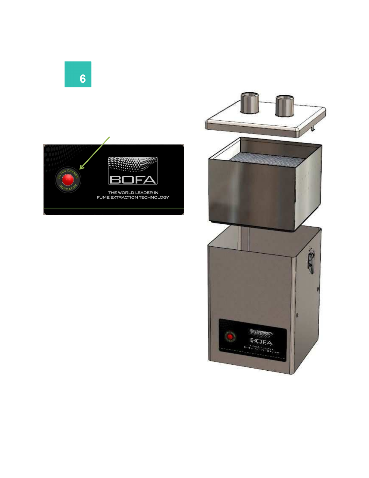
Filter Replacement
The V250 will alert the user when its filters needs to be
replaced. When the filter becomes full the red ‘Filter
Indicator ‘ light next on the left side of the label will glow.
To remove and replace the combined filter follow the
procedure detailed below.
1. Isolate the electrical supply to the extractor
2. Undo the clips on the sides of the unit and remove
the lid.
3. Lift the filter out of the unit. Once removed it is
recommend that the used filters are bagged and
sealed.
4. Lower the new filter into position.
Replace the lid, and fasten the clips.
To remove and replace the pre filter follow the procedure
detailed below.
1. Isolate the electrical supply to the extractor
2. Undo the clips on the sides of the unit and remove
the lid.
3. Lift the pre filter out of the combined filter. Once
removed it is recommend that the used filter is
bagged and sealed.
4. Lower the new filter into the top of the combined
filter.
5. Replace the lid, and fasten the clips.
Note: The filter MUST be fitted when the extractor is in
use.
Page 12
Replacement Parts
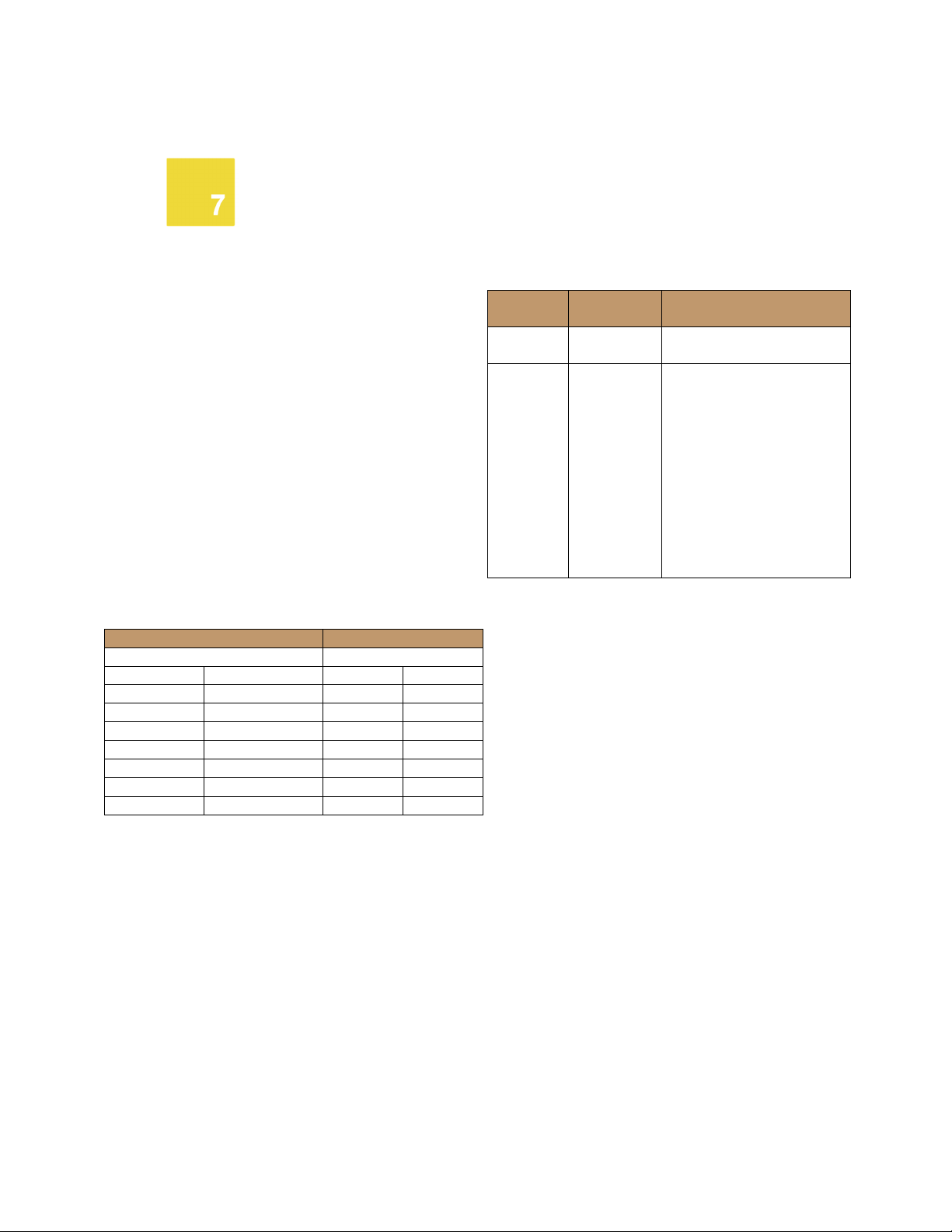
Unit Serial Number:
Date Engineer
Date Engineer
01
Consumable Spares
The V250 contains a pre filter and combined filter. These
should be replaced when instructed to do so by the V250
system (see section 6 for replacing the filters)
To maintain performance it is important that the filters are
replaced with identical BOFA filters. To re-order please refer
to the Filter number printed on the filter installed in your
extraction unit.
Maintenance Protocol
Users can record changes in filter change intervals on the
table below.
Pre Filter Combined Filter
Filter disposal
The combined filter is manufactured from non-toxic
materials. Filters are not re-usable, cleaning used filters is
not recommended. The method of disposal of the used
filters depends on the material deposited on them.
For your guidance
Deposit EWC
Listing*
Non
Hazardous
Hazardous 15 02 02M The type of hazard needs to
*European Waste Catalogue
15 02 03 Can be disposed of as non-
Comment
hazardous waste.
be identified and the
associated risks defined. The
thresholds for these risks
can then be compared with
the amount of material in
the filters to see if they fall
into the hazardous category,
if so, the filters will need to
be disposed of in line with
the local/national
regulations.
Page 13
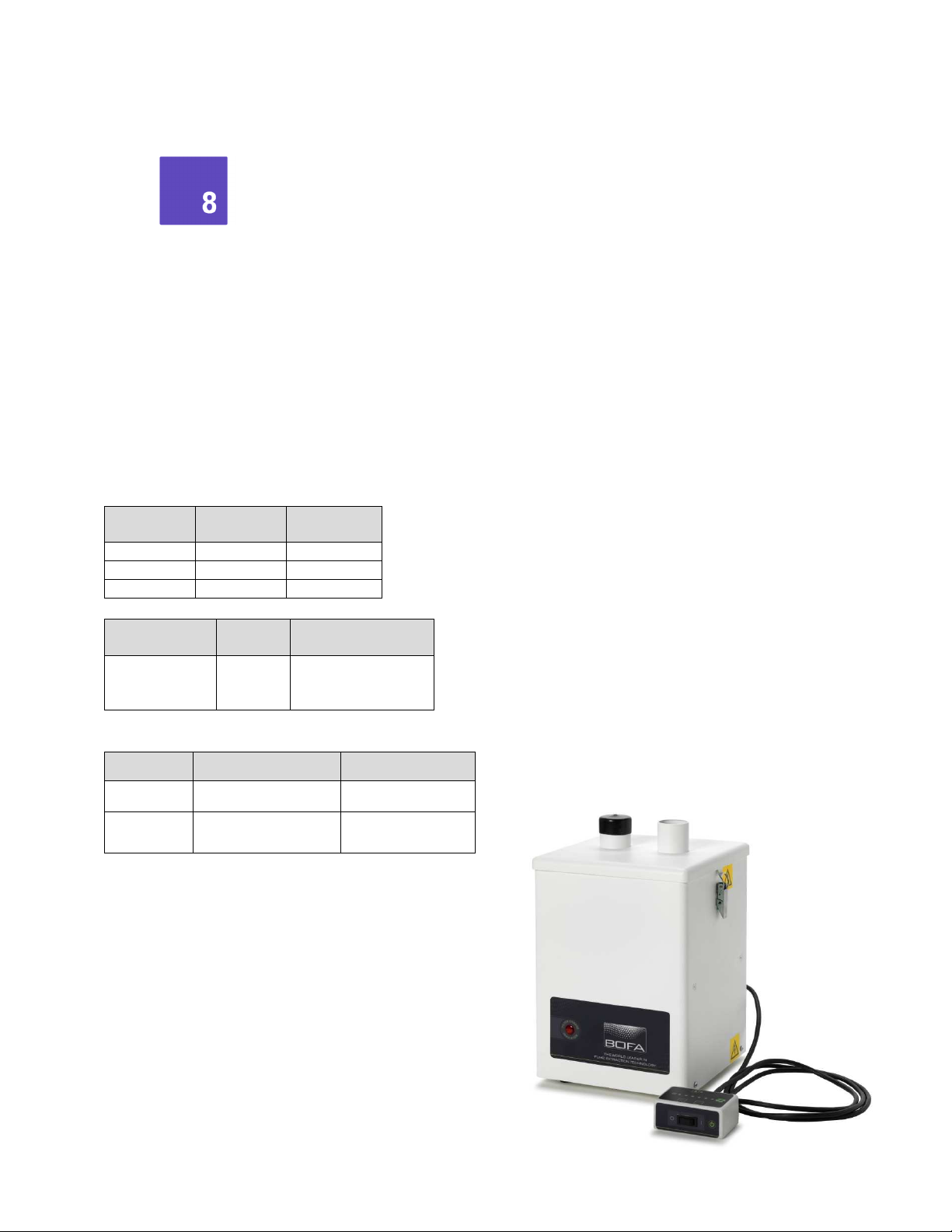
System Specifications
(mm)
(inches)
Depth
260 10.2
Type
01
Unit: V250
Capacity: 180 m³h (106 CFM)
Weight: 10kg (22lbs)
Motor: Centrifugal Fan
Output: 140w
Electrical supply: 115/230V
Hertz: 50/60Hz
Full Load Current: 230v: 1A 115v:1.2A
Noise Level: Below 55db (at typical operating speed)
Size:
Metric
Height 420 16.7
Width 260 10.2
Filter Type Carbon
Carbon filter
(combined
filter)
Filters:
Filter Type Construction Efficiency
Pre Filter Pad
Combined
Filter
Environmental operating range:
Temperature: +5oC to + 40oC
Humidity: Max 80% RH up to 31oC
Max 50% RH at 40oC
Activated
Carbon
Maxi Pleat Construction
Webbing Spacers
Imperial
Amount
with
F7 (96% @ 2 microns
99.997% @ 0.3
microns
)
Page 14

Contact Information
BOFA Headquarters
21-22 Balena Close
Creekmoor industrial Estate
Poole
Dorset
BH17 7DX
UK
Phone: +44 (0) 1202 699444
BOFA Americas
303 S.Madison Street
Staunton
Illnois
62088
USA
Phone: 001 (618) 205-5007
 Loading...