

Boekel 148007 User manual
INSTRUCTION
and
MAINTENANCE
MANUAL
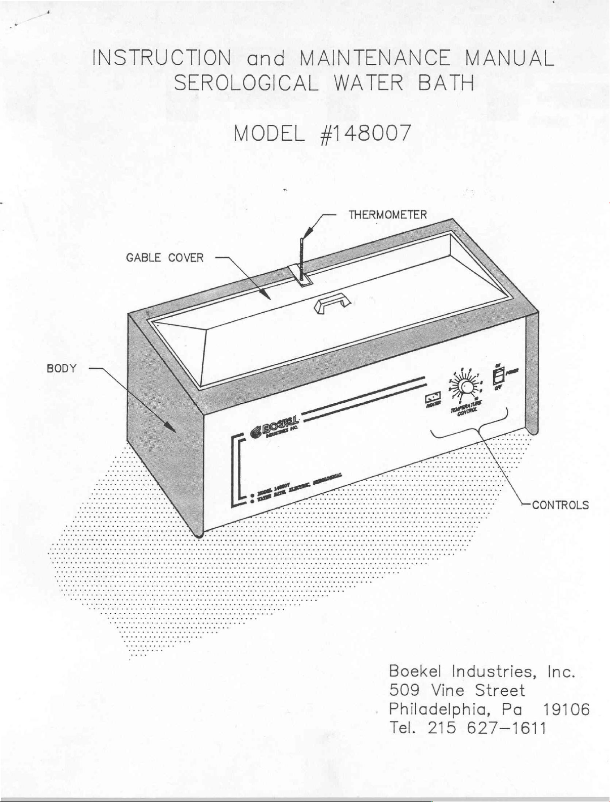
BODY
GABLE
SEROLOGICAL
MODEL
COVER
WATER
#148007
THERMOMETER
BATH
Boekel
509
Philadelphia,
Tel.
Industries,
Vine
215
Street
627-1611
Pa
CONTROLS
Inc.
19106
1.
Introduction
It
and
all
tempting
with
operation.
THIS
May
equipment
maintenance
EQUIPMENT.
create
is
important
operators
to
use
DO
a
failure.
SEROLOGICAL
CATALOG
that
acquainted
it.
NOT
Such
hazardous condition
Specific
requirements
-
UNDER
action
these
with
ANY
will
WATER
NO.
148001
instructions
the
precautions
to
insure
CIRCUMSTANCES
not
leading
BATH
units'
only
operation
will
safe
void
to
be
completely
be
noted
and
-
ALTER
the
operator
before
together
trouble-free
OR
MODIFY
warranty
injury
read
at-
but
or
This
serological
tions
It is
over
(with
55°C
2.
has
added
constructed
table
front
desired
is
terior
including
designed
an
gable
above
Equipment
The
been
measure
Temperature
hydraulic
panel
thermally
point.
type
bracket.
thermometer
indicate
water
bath.
water
procedures
operating
cover)
ambient
Description
water
painted,
of
of
is
temperature
insulated
cool
All
even
units
This
all
temperatures
bath
pharmaceutical,
to
maintain
bath
surface
stainless
control
thermostat.
the
range
or
with
body
both
only
within
is
an
to
when
are
provided
together
thermometer
intended
together
bath
from
upper
the
bath
is
constructed
to
enhance
protection.
steel.
is
achieved
A
adjustment
the
minimize
chamber
with
is
throughout
to
with
clinical
temperature
slightly
temperature
uncovered.
appearance
through
single
operating
control
required
heat
temperature
with
a
stainless
of
suitable
the
be
other
above
of
The
range.
loss
a
mercury
operating
used
laboratory
and
environmental
within
limit
stainless
water
the
knob
and
is
temperature
for
+0.5°C
ambient
of
and
chamber
use
mounted
for
The
to
at
filled
steel
a
variety
applica-
or
to
approximately
steel.
to
provide
is
of
an
adjus-
on
achieving
entire
keep
the
the
boiling
immersion
mounting
range
limits
of
of
work.
less
100°C
ТЕ
ап
also
the
any
unit
ex-
to
the
It
The use
minimizing
stainless
peratures.
to
provide
bracket.
is
recommended
of
this
power
steel
It
clearance
cover
consumption.
and has
also
has
for
that
will
a
a
cut-out
the
the
optimize
This
handle
thermometer
optional
temperature
gable
for
safe
at
the
gable
cover
handling
center
and
cover
control
is
constructed
of
the
thermometer
at
be
high
back
mounting
used.
while
of
tem-
edge
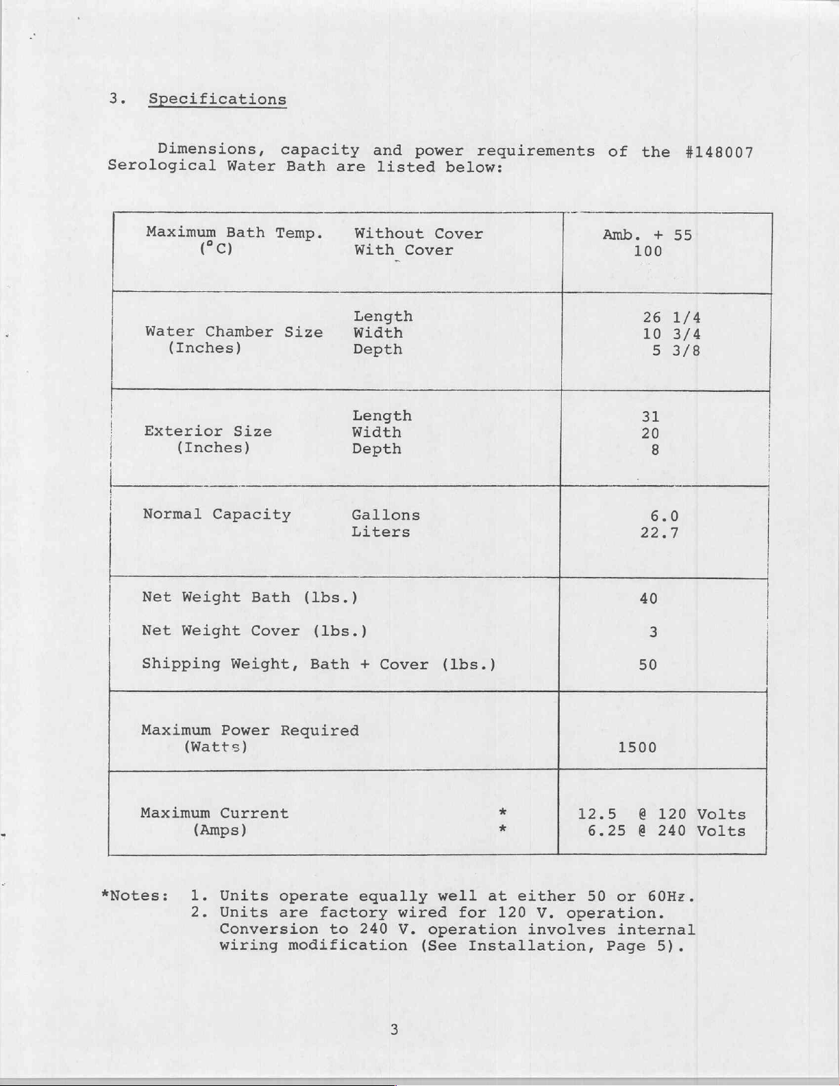
3.
Specifications
Dimensions,
Serological
Maximum
Water
(Inches)
|
Exterior
|
|
|
|
(Inches)
Normal
Water
Bath
(če)
Chamber
Size
Capacity
capacity
Bath
Temp.
Size
are
Without
With
Length
Width
Depth
Length
Width
Depth
Gallons
Liters
and
listed
Cover
power
below:
Cover
requirements
of
Amb.
the
+
100
26
10
513/8
31
20
8
6.0
22.7
#148007
55
1/4
3/4
|
|
i
Net
|
Net
Shipping
Maximum
Maximum
*Notes:
Weight
Weight
Power
(Watts)
Current
(Amps)
+
Units
Nr
eo
Units
Conversion
wiring
Bath
Cover
Weight,
(lbs.)
(lbs.)
Bath
Reguired
operate
are
factory
to
modification
Cover
+
equally
wired
240
V.
(lbs.)
well
for
operation
(See
Installation,
at
120
1500
12.5
6.25
either
V.
involves
50
or
operation.
internal
Page
40
8
50
@
120
@
240
60Hz.
5).
Volts
Volts
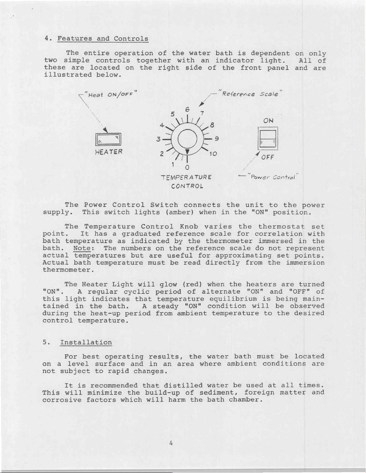
4.
Features
The
two
these
illustrated
simple
are
and
entire
controls
located
below.
Controls
operation
together
on
the
of
right
the
with
water
side
an
of
bath
indicator
is
the
dependent
front
light.
panel
on
All
and
only
of
are
s.
The
supply.
The
point.
bath
bath. Note:
actual
temperature
Actual
thermometer.
Power
This
Temperature
It
temperatures
bath
ON/oFF"
N
へ
>
N
HEATER
Control
switch
has
a
graduated
as
The
numbers
temperature
Switch
lights
Control
indicated
on
but
are
must
TEMPERATURE
CONTROL
connects
(amber)
Knob
reference
by
the
the
reference
useful
be
for
read
ノー
Reference
when
in
varies
scale
thermometer
approximating
directly
the
the
scale
—
the
for
Power
unit
from
Scale
ON
Il
|
A
OFF
Control”
to
"ON"
position.
thermostat
correlation
immersed
do
not
set
the
w
the
in
represent
points.
immersion
power
set
with
the
The
"ON".
this
tained
during
control
5.
on
not
light
in
the
Installation
For
a
level
subject
It is
This will
corrosive
Heater
A
regular
indicates
the
temperature.
best
bath.
heat-up
operating
surface
to
rapid
recommended
minimize
factors
Light
cyclic
period
which
will
that
A
and
changes.
that
the
glow
period
temperature
steady
from
results,
in
an
distilled
build-up
will
harm
(red)
of
"ON"
ambient
the
area
of
the
when
alternate
equilibrium
condition
temperature
water
where
water
ambient
sediment,
bath
the
heaters
"ON"
bath
be
used
foreign
chamber.
is
will
to
must
conditions
at
and
being
be
the
are
"OFF"
observed
desired
be
located
all
matter
turned
of
main-
are
times.
and
V.
power
supply,
be
performed
mance
The
with
A.
CAUTION:
SUPPLY
THE
water
supply.
a
wiring
the
Being
power
resting
protect
PROPER
bath
by
qualified
following
certain
source,
NEVER
UNLESS
has
If
change
on
a
its
YOU
VOLTAGE
been
it
is
is
detailed
that
turn
soft
finish.
CONNECT
ARE
AND
factory
desired
required.
service
the
it
surface
THE
CERTAIN
SUITABLY
to
personnel
instructions:
unit
upside
such
BATH
THAT
wired
operate
This
is
disconnected
down
as
TO
A
IT
GROUNDED.
for
operation
with
wiring
and
with
cardboard
POWER
IS
OF
change
in
strict
its
240
from
top
or
with
V.
power
should
confor-
any
surface
cloth
120
to
Remove
screw
Locate
at
the
the
fasteners
the
edge
in-line
Wiring
for
#1 - "А".
Wiring
#1
To
(1)
(2)
(3)
(4)
Replace
"B"
for
В".
change
Loosen
Remove
#1
and
Move wire
Re-tighten
wire
above.
bottom
terminal
with
120
240
from
screws
the
#3.
ends
bottom
of
the
V.
V.
short
from
all
are
plate
for
the
Heater
120
plate
later
block
internal
operation
operation
V.
to
on
terminals
jumper
terminal
terminal
fully
using
-
being
replacement.
which
partition
Light
is
is
240
V.
wire
#5
screws,
inserted.
same
sure
is
mounted
(See
Illustration
as
shown
as
shown
operation:
#1,
#3
between
to
terminal
screws
to
and
and
being
removed
retain
on
a
approximately
on
Illustration
on
Illustration
#5.
terminals
#3.
certain
the
bracket
#1).
that
in
step
Turn
from
unit
240
Volt
CAUTION:
CUT
THE
ADAPTER
right
OR
REMOVE
POWER
side
power
DO
CORD
PLUG.
up
source.
NOT,
THE
PLUG.
-
it
UNDER
THIRD
DO
is
now
ANY
(GROUND)
NOT USE
ready
CIRCUMSTANCES,
PRONG
A
TWO-PRONG
for
operation
FROM
 Loading...