

Page 1
1
Suzhou BOE CHATANI Electronics Co., LTD.
LCM APPROVAL
Part Name : LCM
MODEL NO : BOEV320WX1
Part Name : 2602802001
Effective Date : 2012.05.09
Suzhou BOE CHATANI Electronics Co.,LTD
APP CKECK APPV
Approved by:
APP/DATE CHECK/DATE APPV/DATE
PDF 文件使用 "pdfFactory Pro" 试用版本创建 www.fineprint.cn
Page 2
2
Revised record
Ver Date Revision content Page Revised
1.0 2012-05-09 First release all
Cheng
xiaoqing
PDF 文件使用 "pdfFactory Pro" 试用版本创建 www.fineprint.cn
Page 3
3
Contents
No.
1.0 GENERAL DESCRIPTION 4
2.0 ABSOLUTE MAXIMUM RATING 5
3.0 ELECTRICAL SPECIFICATIONS 6
4.0 OPTICAL SPECIFICATION 7
5.0 INTERFACE CONNECTION 9
6.0 SIGNAL TIMING SPECIFICATION 12
7.0 SIGNAL TIMING WAVEFORMS OF INTERFACE SIGNAL 12
8.0 INPUT SIGNALS, BASIC DISPLAY COLORS&GRAY SCALE OF COLORS 13
Item Page
9.0 POWER SEQUENCE 14
10.0 MECHANICAL CHARACTERISTICS 14
11.0 RELIABLITY TEST 16
12.0 HANDLING & CAUTIONS 16
13.0 OPTICAL CHARACTERISTICS 17
14.0 MECHANICAL CHARACTERTISTICS 19
15.0 PACKING 21
16.0 DEFINITION OF LABELS 21
PDF 文件使用 "pdfFactory Pro" 试用版本创建 www.fineprint.cn
Page 4
4
1.0 GENERAL DESCRIPTION
1.1 Introduction
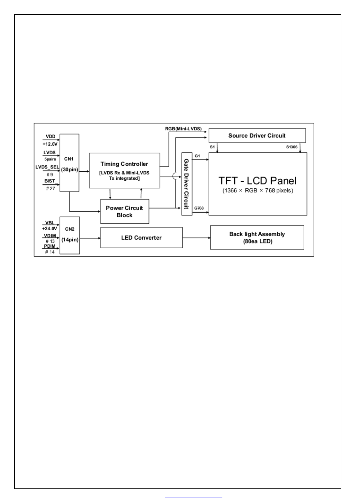
BOE320WX1 is a color active matrix TFT LCD module using amorphous silicon TFT's (Thin Film Transistors)
as an active switching devices. This module has a 31.5 inch diagonally measured active area with WXGA
resolutions (1366 horizontal by 768 vertical pixel array). Each pixel is divided into RED, GREEN, BLUE dots
which are arranged in vertical stripe and this module can display 16.7M colors. The TFT-LCD panel used for
this module is adapted for a low reflection and higher color type.
1.2 Features
●LVDS Interface with 1 pixel / clock
●High-speed response
●Low color shift image quality
●8-bit color depth, display 16. 7M colors
●High luminance and contrast ratio, low reflection and wide viewing angle
●DE (Data Enable) only
●AFFS technology is applied for high display qualify
●RoHS/Halogen Free
1.3 Application
●Home Alone Multimedia TFT-LCD TV
●Display Terminals for Control System
●High Definition TV(HD TV)
●AV application Products
1.4 General Specification
PDF 文件使用 "pdfFactory Pro" 试用版本创建 www.fineprint.cn
Page 5
5
The followings are general specifications at the model BOEV320WX1.
< Table 1,General Specifications >
Items Specifications Unit
Screen Diagonal 31.5 inch
Active Area 697.685(H) ×392.256(V) mm
Pixels H x V 1366(H)×768(V) pixels
Pixel Pitch 0.17025×RGB×0.51075 mm
Pixel Arrangement Pixels R.G.B. Vertical Stripe
White Luminance
350minimum,400typical
cd/m2 (LED@120mA Per Input Pin )
Display colors 16.7M(8bit-true) colors
Display mode Transmission mode,Normally Black
Outline Dimension 741.4 (W) x 435.8(H) x 15.2 (T) typical mm
Surface Treatment Haze 10%, 3H
Back-light Lower edge side, 2-LED Lighting Bar type Note 1
PD : 7.1 (max)
Power Consumption
PBL : 33.6W (max) Note 2
Ptotal : 40.7 (max)
Notes : 1. LED Lighting Bar (2*input pins)
2. PLED=Input pins* VPIN×IPIN
2.0 ABSOLUTE MAXIMUM RATINGS
The followings are maximum values which, if exceed, may cause faulty operation or damage to the unit. The
operational and non-operational maximum voltage and current values are listed in Table 2.
< Table 2. Absolute Maximum Ratings>
Item Symbol
Min. Max. Unit Conditions
Power Supply Voltage VDD VSS-0.3 13.2 V
Ta=25ºC
TOP 0 +50 ºC
Operating Temperature
TSUR 0 +60 ºC
Storage Temperature TST -20 +60 ºC
Note 1)
Operating Ambient Humidity Hop 10 80 %RH
Storage Humidity Hst 10 80 %RH
Item Symbol
*LED
Current IPIN - 120 mA
Channel
*LED
Voltage VPIN 58 70 V
Channel
Min. Max. Unit Conditions
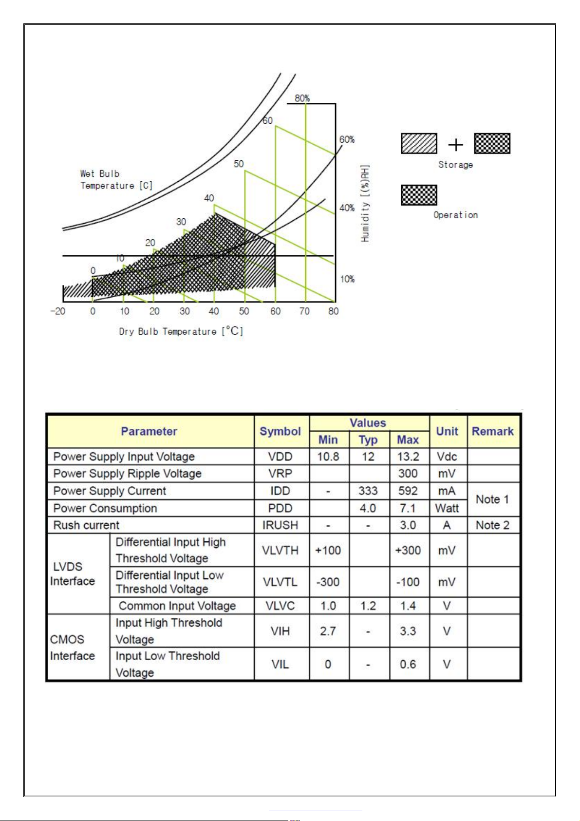
Note : 1) Temperature and relative humidity range are shown in the figure below.Wet bulb temperature should
be 39 °C max. and no condensation of water.
PDF 文件使用 "pdfFactory Pro" 试用版本创建 www.fineprint.cn
Page 6
6
3.0 ELECTRICAL SPECIFICATIONS
3.1 Electrical Specifications
< Table 3. Electrical specifications > [Ta=25±2 ℃]
Note 1 : The supply voltage is measured and specified at the interface connector of LCM.
The current draw and power consumption specified is for VDD=12.0V,
Frame rate fV=60Hz and Clock frequency = 75.4MHz.
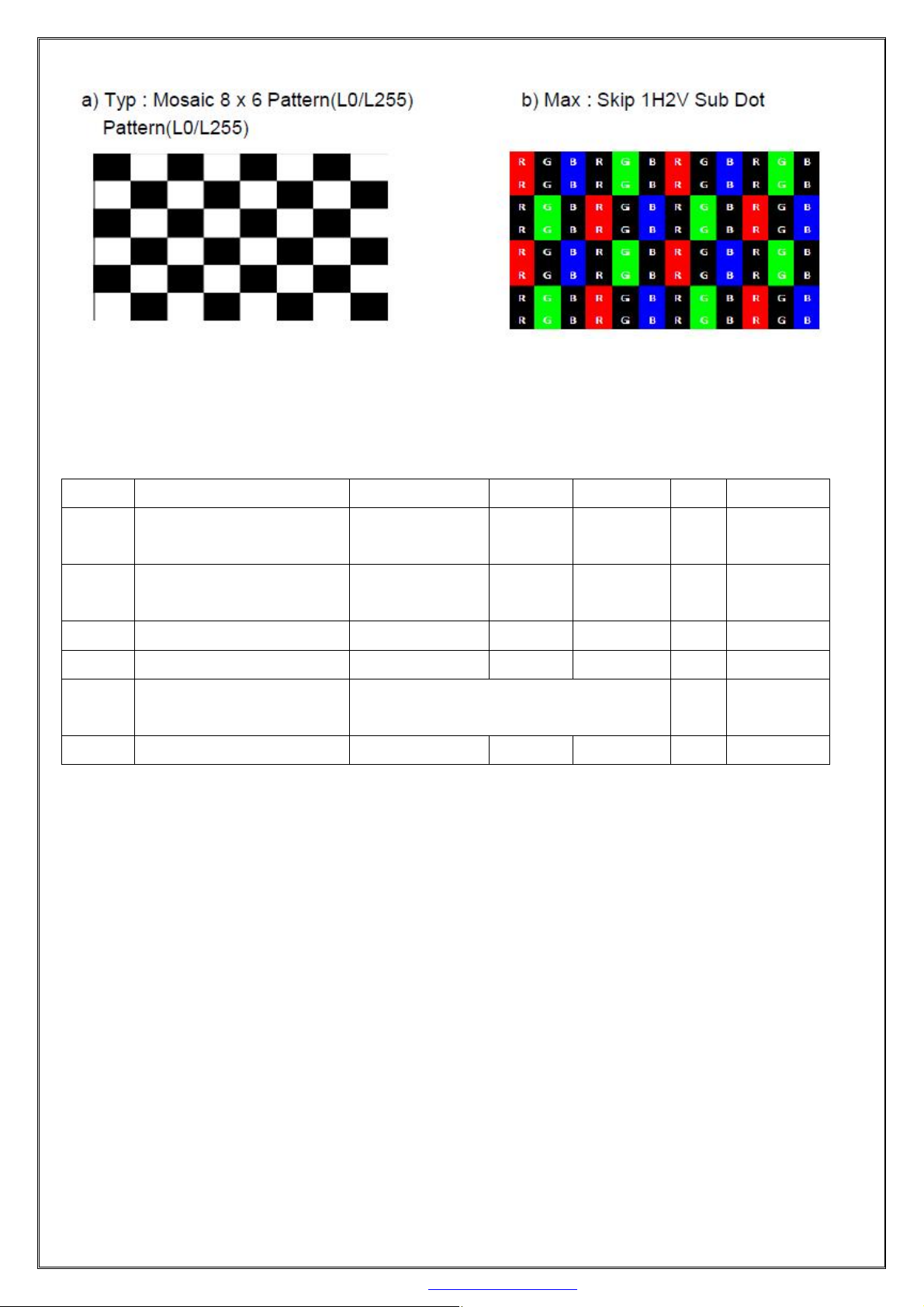
Test Pattern of power supply current
PDF 文件使用 "pdfFactory Pro" 试用版本创建 www.fineprint.cn
Page 7
7
Note 2 : The duration of rush current is about 2ms and rising time of Power Input is 1ms(min)
3.2 Backlight Unit
< Table 4. Backlight Unit >
Symbol
VPIN LED Light Bar Input Voltage
Per Input Pin
IPIN LED Light Bar Input Current
Per Input Pin
PBL LED Power Consumption - 30.72 - W Note3
- the single lm rank 30 - - lm
- LED color Rank 1C、1D、1E、1F、1G、1H\ABE、ABF、ABG、
- LED Life-Time 30,000 - - Hrs Note4
Parameter Min. Typ. Max. Units Condition
58 64 70 V
Duty 100%
- 120*4 - mA Note1,2
-
ABH、ABI、ABK、ABL、ABM、ABN
Note1: There are one light bar ,and the specified current is input LED chip 100% duty current
Note2: The sense current of each input pin is 120mA
Note3: PBL=4 Input pins*VPIN ×IPIN
Note4: The lifetime is determined as the time at which luminance of LED become 50% of the initial brightness
or not normal lighting at IPIN=120mA*4 on condition of continuous operating at 25 ±2 ℃
4.0 OPTICAL SPECIFICATION
4.1 Overview
The test of optical specifications shall be measured in a dark room (ambient luminance﹤1 lux
andtemperature=25±2℃) with the equipment of Luminance meter system (Goniometer system and PR730) and
test unit shall be located at an approximate distance 50cm from the LCD surface at a viewing angle of θ and Φ
equal to 0 . We refer to θØ=0(=θ3) as the 3 o‟clock direction (the “right”), θØ=90(= θ12) as the 12 o‟clock
direction (“upward”), θØ=180(= θ9) as the 9 o‟clock direction (“left”) and θØ=270(= θ6 ) as the 6 o‟clock
direction (“bottom”). While scanning θ and/or Ø, the center of the measuring spot on the Display surface shall
stay fixed. The measurement shall be executed after 30 minutes warm-up period. VDD shall be 12.0V +/-10%
at 25℃. Optimum viewing angle direction is 6 ‟clock.
PDF 文件使用 "pdfFactory Pro" 试用版本创建 www.fineprint.cn
Page 8

8
TYP.
TYP.
4.2 LCM Optical Specifications
Parameter Symbol Condition Min Typ Max Unit Remark
[VDD = 12.0V,Frame rate = 60Hz,, IBL = 120mA*4, Ta =25±2 ℃]
<Tabel 5.Optical Table>
Viewing Angel
Horizontal
Vertical
θ3
θ9
CR>10
θ12
θ6
89
89
89
89
Color Temperature - 9,000
Color Gamut - 72
Contrast ratio CR 900:1 1200:1
Luminance of White Yw 350 400 -
△Y 70 75
Wx 0.305
Reproduction
of color
White
Red
Green
Wy 0.315
Rx 0.630
Ry 0.340
Gx 0.300
θ=0°
(Center)Normal
Viewing Angel
-0.03
Gy 0.630
Bx 0.148
-
+0.03
Deg.
Deg.
Note1
Deg.
Deg.
K
%
Note2
2
cd/m
Note3
% Note4
Note5
Response Time
Gamma Scale 2.0
Blue
G to G Tg - 8 10 ms Note6
By
0.068
2.2
2.4 Note7
Note :
1. Viewing angle is the angle at which the contrast ratio is greater than 10. The viewing are determined for the
horizontal or 3, 9 o‟clock direction and the vertical or 6, 12 o‟clock direction with respect to the optical axis
which is normal to the LCD surface.
2. Contrast measurements shall be made at viewing angle of = 0 and at the center of the LCD surface.
Luminance shall be measured with all pixels in the view field set first to white, then to the dark (black) state.
(See Figure1 shown in Appendix) Luminance Contrast Ratio (CR) is defined mathematically.
3.Center Luminance of white is defined as the LCD surface. Luminace shall be measured with all pixels in the view field
set first to white. This measurement shall be taken at the locations shown in Figure 2 for a total of the measurement per
display。
4. The White luminance uniformity on LCD surface is then expressed as :
ΔY = ( Minimum Luminance of 5points / Maximum Luminance of 5points ) * 100 (See Figure 2 shown in
PDF 文件使用 "pdfFactory Pro" 试用版本创建 www.fineprint.cn
Page 9

9
Appendix).
5. The color chromaticity coordinates specified in Table 5.shall be calculated from the spectral data measured
with all pixels first in red, green, blue and white. Measurements shall be made at the center of the panel.
6. Response time Tg is the average time required for display transition by switching the input signal as below
table and is based on Frame rate fV =60Hz to optimize. Each time in below table is defined as Figure 2and shall
be measured by switching the input signal for “any level of gray(bright)”and “any level of gray(dark)”.
7. Definition of Transmittance (T%) :
Module is with white(L255) signal input
5.0 INTERFACE CONNECTION.
5.1 Electrical Interface Connection
5.1.1 LED Light Bar
< Table 6. LED Light Bar>
Pin No Symbol Description
1 IRLED1 Channel Current Feedback
2 IRLED2 Channe2 Current Feedback
3 VLED LED power supply
4 VLED LED power supply
5 IRLED3 Channe3 Current Feedback
6 IRLED4 Channe4 Current Feedback
CONNECTOR CI0106S0000
PDF 文件使用 "pdfFactory Pro" 试用版本创建 www.fineprint.cn
Page 10

10
5.1.2 Module Input Signal & Power
-Connector : IS100-L30B-C23(Manufactured by UJU) or Equivalent.
< Table 7. Open Cell Input Connector Pin Configuration >
Notes : 1. NC(Not Connected) : This pins are only used for BOE internal operations.
2.Input Level of LVDS signal is based on the IEA 664 Standard.
3. LVDS_SEL: This pin is used for selecting LVDS signal data format.
If this Pin : High (3.3V) or Open (NC) Normal NS LVDS format
Otherwise : Low(GND) JEIDA LVDS format
4. BIST : This pin is used for selecting display pattern mode when input DE or input CLOCK quits toggling.
If this Pin : Low (GND) or Open (NC)Free run mode(Black Pattern)
Otherwise : High( 3.3V) BIST mode(BIST Pattern)
Sequence : On = VDD ≥LVDS Option , BIST Option ≥Interface signal
PDF 文件使用 "pdfFactory Pro" 试用版本创建 www.fineprint.cn
Page 11

11
Off = Interface signal ≥ LVDS Option , BIST Option ≥ VDD
5.2 LVDS Interface
-LVDS Receiver : Timing Controller (LVDS Rx merged) / LVDS Data : Pixel Data
< Table 8. Open Cell Input Connector Pin Configuration >
PDF 文件使用 "pdfFactory Pro" 试用版本创建 www.fineprint.cn
Page 12

12
6.0 SIGNAL TIMING SPECIFICATION
6.1 Timing Parameters (DE only mode)
< Table 9. Timing Table >
Notes: This product is DE only mode. The input of Hsync & Vsync signal does not have an effect on normal
operation.
7.0 Signal Timing Waveform
PDF 文件使用 "pdfFactory Pro" 试用版本创建 www.fineprint.cn
Page 13

13
8.0 Input Signals, Basic Display Colors and Gray Scale of Colors
< Table 10. Input Signal and Display Color Table >
PDF 文件使用 "pdfFactory Pro" 试用版本创建 www.fineprint.cn
Page 14

14
9.0 POWER SEQUENCE
To prevent a latch-up or DC operation of the Open Cell, the power on/off sequence shall be as shown in
below
< Table 11. Sequence Table >
10.0 MECHANICAL CHARACTERISTICS
10.1 Dimensional Requirements
FIGURE 6 (located in Appendix) shows mechanical outlines for the opencell HV320WX2-201.Other parameters are
shown in Table 12.
<Table 12. Dimensional Parameters>
Item Min Typ Max Unit Note
Module
Size
Bezel
Active Area
Horizontal 740.8 741.4 742.0 mm
Vertical 435.3 435.8 436.3 mm
Thickness 14.9 15.2 15.5 mm
Horizontal - 705.4 - mm
Vertical - 399.8 - mm
Horizontal - 697.685 - mm
Vertical - 392.256 - mm
Weight 5700 g
D/B Wire length
- 550 - mm
PDF 文件使用 "pdfFactory Pro" 试用版本创建 www.fineprint.cn
Page 15

15
10.2 Mounting
See FIGURE 5. (shown in Appendix)
10.3 Anti-Glare and Polarizer Hardness.
The surface of the LCD has an anti-glare coating to minimize reflection and a coating to reduce scratching.
PDF 文件使用 "pdfFactory Pro" 试用版本创建 www.fineprint.cn
Page 16

16
10.4 Light Leakage
There shall not be visible light from the back-lighting system around the edges of the screen as seen from a
distance 50cm from the screen with an overhead light level of 300lux.
11.0 RELIABLITY TEST
The Reliability test items and its conditions are shown in below.
< Table 13. Reliability Test Condition >
12.0 HANDLING & CAUTIONS
(1) Cautions when taking out the module
●Pick the pouch only, when taking out module from a shipping package.
(2) Cautions for handling the module
●As the electrostatic discharges may break the LCD module, handle the LCD module with care. Peel a protection sheet
off from the LCD panel surface as slowly as possible.
●As the LCD panel and back - light element are made from fragile glass material,impulse and pressure to the LCD
module should be avoided.
●As the surface of the polarizer is very soft and easily scratched, use a soft dry cloth without chemicals for cleaning.
●Do not pull the interface connector in or out while the LCD module is operating.
PDF 文件使用 "pdfFactory Pro" 试用版本创建 www.fineprint.cn
Page 17

17
●Put the module display side down on a flat horizontal plane.
ity
Environment
Method
●Handle connectors and cables with care.
(3) Cautions for the operation
●When the module is operating, do not lose CLK, ENAB signals. If any one of these signals is lost, the LCD panel
would be damaged.
●Obey the supply voltage sequence. If wrong sequence is applied, the module would be damaged.
(4) Cautions for the atmosphere
●Dew drop atmosphere should be avoided.
●Do not store and/or operate the LCD module in a high temperature and/or humidity atmosphere. Storage in an
electro-conductive polymer packing pouch and under relatively low temperature atmosphere is recommended.
(5) Cautions for the module characteristics
●Do not apply fixed pattern data signal to the LCD module at product aging.
●Applying fixed pattern for a long time may cause image sticking.
(6) Other cautions
●Do not disassemble and/or re-assemble LCD module.
●Do not re-adjust variable resistor or switch etc.
●When returning the module for repair or etc., Please pack the module not to be broken. We recommend to use the
original shipping packages.
13.0 LCM Optical Characteristics
Item Symbol Min. Typ. Max. Unit Note
Luminance Of White (central) Lc
Brightness Uniformity
( 9 pts)
Central Chromaticity of White
Temperature 25±3℃
Humid
Test distance 50±3 cm □others( ____ cm )
Viewing cone □0.2° ▓others( 1° )
Test
Condit
ions
Electricity
(Max. luminance)
Test equipment
Measured Area LCM Module open lighting area
Lu 70 75 - % Note 1
x 0.275 0.305 0.335
y 0.285 0.315 0.345
65±20%
Under 10 Lux
□ Lamp Current mA
▓ LED Driving Current Per Input Pin 120 mA
▓ Power consumption 30.7 Watt
▓ BM-7 ▓others( _BM-7_ ) Corrective value for Brightness and Color (x ; y)
Should be added while using SR-3.
350 400
rms
nit
CIE 1931(x, y)
[Base On BM-7]
See attachment “ test detail-1, -2 “
Others Measurement should be done after lighting for at least 30 mins
Note :Brightness Uniformity = Lmin / Lmax × 100%
PDF 文件使用 "pdfFactory Pro" 试用版本创建 www.fineprint.cn
Page 18

18
The centre point should be the maximal brightness of 9 measuring points.
Note:
(1)Measurement Setup
The LCD module should be stabilized at 25℃ for 30 minutes to avoid abrupt
temperature change during measuring. In order to stabilize the luminance, the measurement should be executed after
lighting backlight for 30 minutes in a windless room.
Figure 10 Measurement Setup
□ flat ■ vertical
LCM Module
Insulation
plastics
Viewing cone
Equipment SR-3
BM-7
Distance
L=50±3cm
Wall
Insulation plastics
Table
Note: The BLU must be grounded.
Measurements are performed perpendicular to the display screen surface.
(2)Definition of Viewing Angle
Figure 11 Definition of Viewing Angle
LCM Module
Viewing cone
Vrewing cone
Vrewing cone
Distance L=50±3cm
Equipment
BM-7
(3)The position of measured points
PDF 文件使用 "pdfFactory Pro" 试用版本创建 www.fineprint.cn
Page 19

19
14.0 Mechanical Characteristics
TFT-LCD Module Outline Dimensions (Front view)
PDF 文件使用 "pdfFactory Pro" 试用版本创建 www.fineprint.cn
Page 20

20
Note (1) Please refer to the attached drawings for more information of front and back outline
dimensions.
PDF 文件使用 "pdfFactory Pro" 试用版本创建 www.fineprint.cn
Page 21

21
15.0 PACKING
15.1 CARTON
15.2 PALLET
Packed cartons will be placed on the pallet, each layer 4box, three horizontal and one vertical placed, each
pallet placed 3 layer. Pallet first use of stretch film packaging layer 3 to 5, then use the sealing belted with
#-shaped package.
16.0 DEFINITION OF LABELS
16.1 LOT NO. LABEL
PDF 文件使用 "pdfFactory Pro" 试用版本创建 www.fineprint.cn
Page 22

22
16.2 BOECT MODULE LABEL
16.3 CARTON LABEL
PDF 文件使用 "pdfFactory Pro" 试用版本创建 www.fineprint.cn
 Loading...