

BOE HR270WU3-300 Specification
Global LCD Panel Exchange Center
HR270WU3
300 Preliminary Product Specification
THIS SPECIFICATION IS THE PROPERTY OF BOE DT AND SHALL NOT BE
REPRODUCED OR COPIED WITHOUT THE WRITTEN PERMISSION OF BOE DT AND
MUST BE RETURNED TO BOE DT UPON ITS REQUEST
-
www.panelook.com
PROPRIETARY NOTE
BEIJING BOE Display TECHNOLOGY
SPEC. NUMBER
z
B2010-8002-O (1/3)
One step solution for LCD / PDP / OLED panel application: Datasheet, inventory and accessory!
PRODUCT GROUP
TFT-LCD
Rev.P0
ISSUE DATE
2013.03.26
PAGE
PAGE
X
OF 30
A4(210 X 297)
A4(210 X 297)
www.panelook.com
Global LCD Panel Exchange Center
REVISION HISTORY
www.panelook.com
PRODUCT GROUP
TFT- LCD PRODUCT Rev.P0 Mar. 26. 13’
REV. ECN No. DESCRIPTION OF CHANGES DATE PREPARED
Rev.P0 Initial Release Mar. 26. 13’ LJ.Xiao
REV
ISSUE DATE
SPEC. NUMBER
z
B2010-8002-O (2/3)
One step solution for LCD / PDP / OLED panel application: Datasheet, inventory and accessory!
SPEC. TITLE
HR270WU3-300 Product Specification_Rev.P0
PAGE
2
OF 30
A4(210 X 297)
www.panelook.com
Global LCD Panel Exchange Center
Content
7.0
Signal Timing Waveforms of Interface Signal
15
www.panelook.com
PRODUCT GROUP
TFT- LCD PRODUCT
REV
Rev.P0
ISSUE DATE
Mar. 26. 13’
s
No. Item Page
1.0 General Description 4
2.0 Absolute Maximum Ratings 6
3.0 Electrical Specifications 7
4.0 Optical Specifications 8
5.0 Interface Connection 10
6.0 Signal Timing Specifications 13
8.0 Input Signals, Display Colors & Gray Scale of Colors 17
9.0 Power Sequence 18
10.0 Mechanical Characteristics 19
11.0 Reliability Test 20
12.0 Handling& Cautions 21
13.0 Product Serial Number 22
14.0 Packing 23
15.0 Appendix 25
SPEC. NUMBER
S
B2010-8002-O (3/3)
One step solution for LCD / PDP / OLED panel application: Datasheet, inventory and accessory!
SPEC. TITLE
HR270WU3-300 Product Specification_Rev.P0
PAGE
Z
OF 30
A4(210 X 297)
www.panelook.com
Global LCD Panel Exchange Center
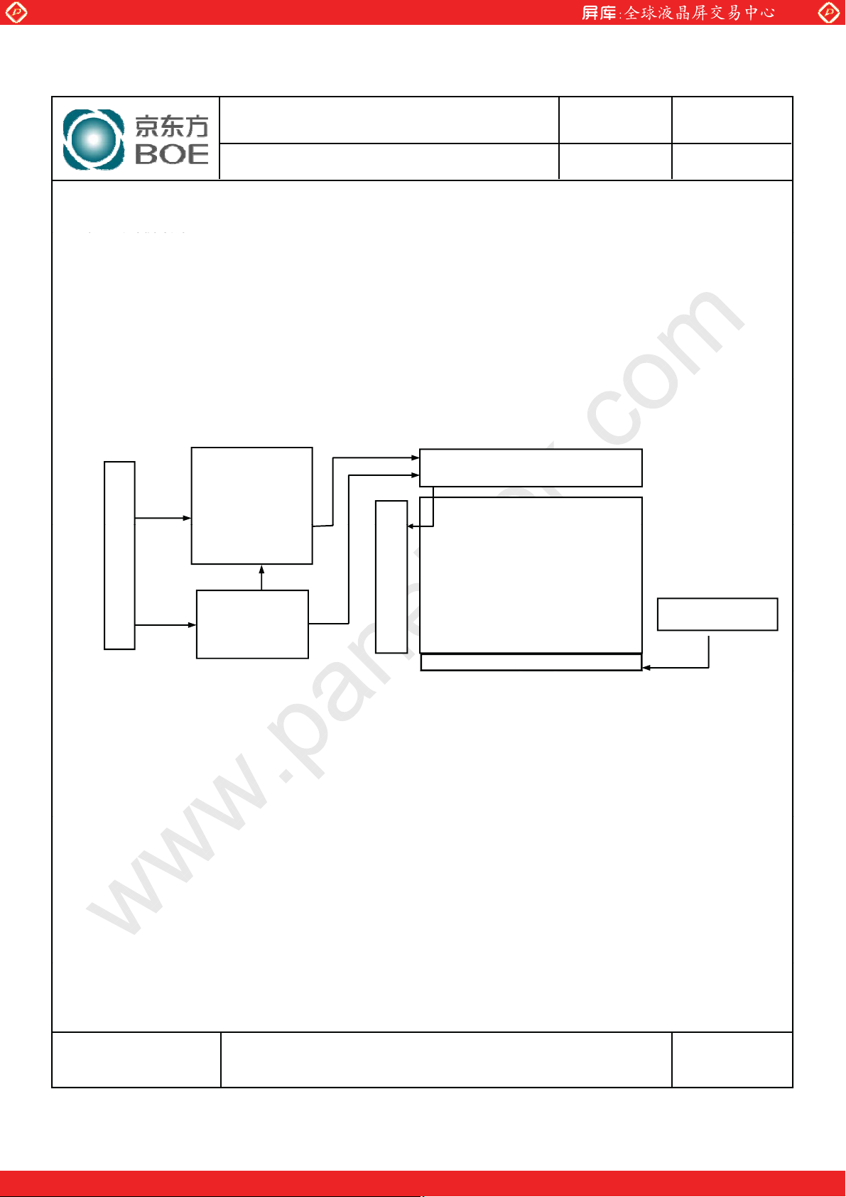
1.1 Introduction
Ý
+
gg
z
LV
DS Interface with 2 pixel / clock
www.panelook.com
PRODUCT GROUP
TFT- LCD PRODUCT
REV
Rev.P0
1.0 GENERAL DESCRIPTION
HR270WU3-300 is a color active matrix TFT LCD module using amorphous silicon TFT's
(Thin Film Transistors) as an active switching devices. This module has a 27.0 inch
diagonally measured active area with FHD resolutions (1920 horizontal by 1080 vertical
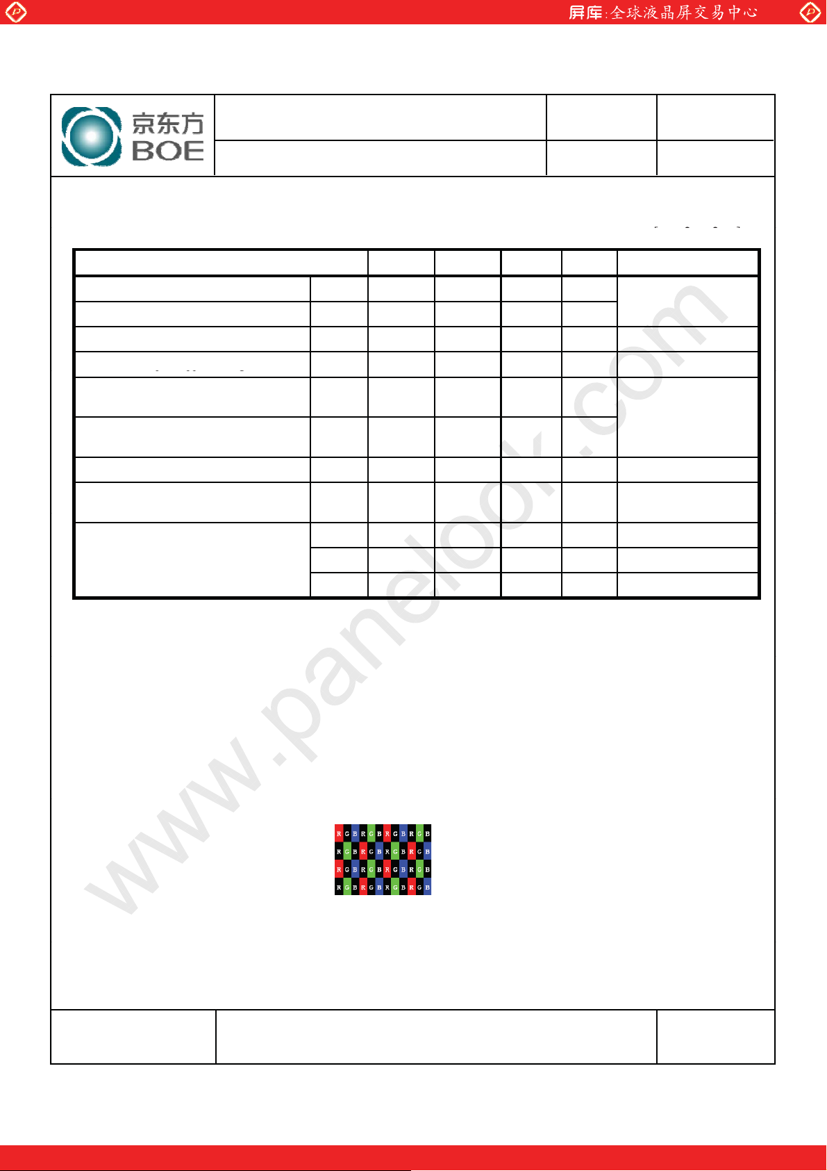
pixel array). Each pixel is divided into RED, GREEN, BLUE dots which are arranged in
vertical stripe and this module can display 16.7M colors. The TFT-LCD panel used for this
module is adapted for a low reflection and higher color type.
Connector (CN
LVDS
Input
Signal
LVDS Rx
+
T/CON
Gate Driver
Mini LVDS Tx
Source Driver
TFT LCD Panel
ISSUE DATE
Mar. 26. 13’
1920
VDD
1
)
1.2 Features
z High-speed response
z 8-bit (Real) color depth, display 16. 7M colors
z High luminance and contrast ratio, low reflection and wide viewing angle
z DE (Data Enable) only
z RoHS/Halogen Free
z Gamma Correction
DC/DC
Gamma
Vcom
LED Lighting Bar
1080
LED Connector
SPEC. NUMBER
S
B2010-8002-O (3/3)
One step solution for LCD / PDP / OLED panel application: Datasheet, inventory and accessory!
SPEC. TITLE
HR270WU3-300 Product Specification_Rev.P0
PAGE
[
OF 30
A4(210 X 297)
www.panelook.com
Global LCD Panel Exchange Center
Display colors
16.7M
colors
www.panelook.com
PRODUCT GROUP
TFT- LCD PRODUCT
1.3 Application
zDesktop Type of PC & Workstation Use
z Display Terminals for Control System
z Monitors for Process Controller
1.4 General Specification
The followings are general specifications at the model HR270WU3-300.
<Table 1. General Specifications>
Parameter Specification Unit
REV
Rev.P0
ISSUE DATE
Mar. 26. 13’
Remarks
Active area
Number of pixels
Pixel pitch
597.888(H) Ý 336.312(V)
1920(H) ശ1080(V)
0.3114(H) ശ0.3114(V)
mm
pixels
mm
Pixel arrangement RGB Vertical stripe
Display mode Normally Black
Open Cell
Transmittance
4.85 %
Weight TBD (Typ.) g
Surface Treatment
Power Consumption P
Haze 25%, 3H
: 7w (max)
D
At center
point with
BOE BLU
SPEC. NUMBER
S
SPEC. TITLE
HR270WU3-300 Product Specification_Rev.P0
B2010-8002-O (3/3)
One step solution for LCD / PDP / OLED panel application: Datasheet, inventory and accessory!
PAGE
\
OF 30
A4(210 X 297)
www.panelook.com
Global LCD Panel Exchange Center
The followi
ڑ ڋ
ړ ڋ
ڌ ڋ ڋ
ۈۄڿۄۏ۔ٻڃڀڭڣڄ
ڍ ڋ
ڏ ڋ
ڪ ۋ ۀ ۍڼ ۏۄۉ ۂٻڭ ڼ ۉ ۂ ۀ
ڮ ۏۊ ۍڼ ۂ ۀ ٻڭ ڼ ۉ ۂ ۀ
ڭۀۇڼۏۄۑۀٻڣ
ې
ڋ
ڍ ڋ ڏ ڋ ڑ ڋ ړ ڋڈڍ ڋ
گ ۀ ۈ ۋ ۀ ۍڼ ۏې ۍۀ ٻڃഴڞ ڄ
www.panelook.com
PRODUCT GROUP
TFT- LCD PRODUCT
REV
Rev.P0
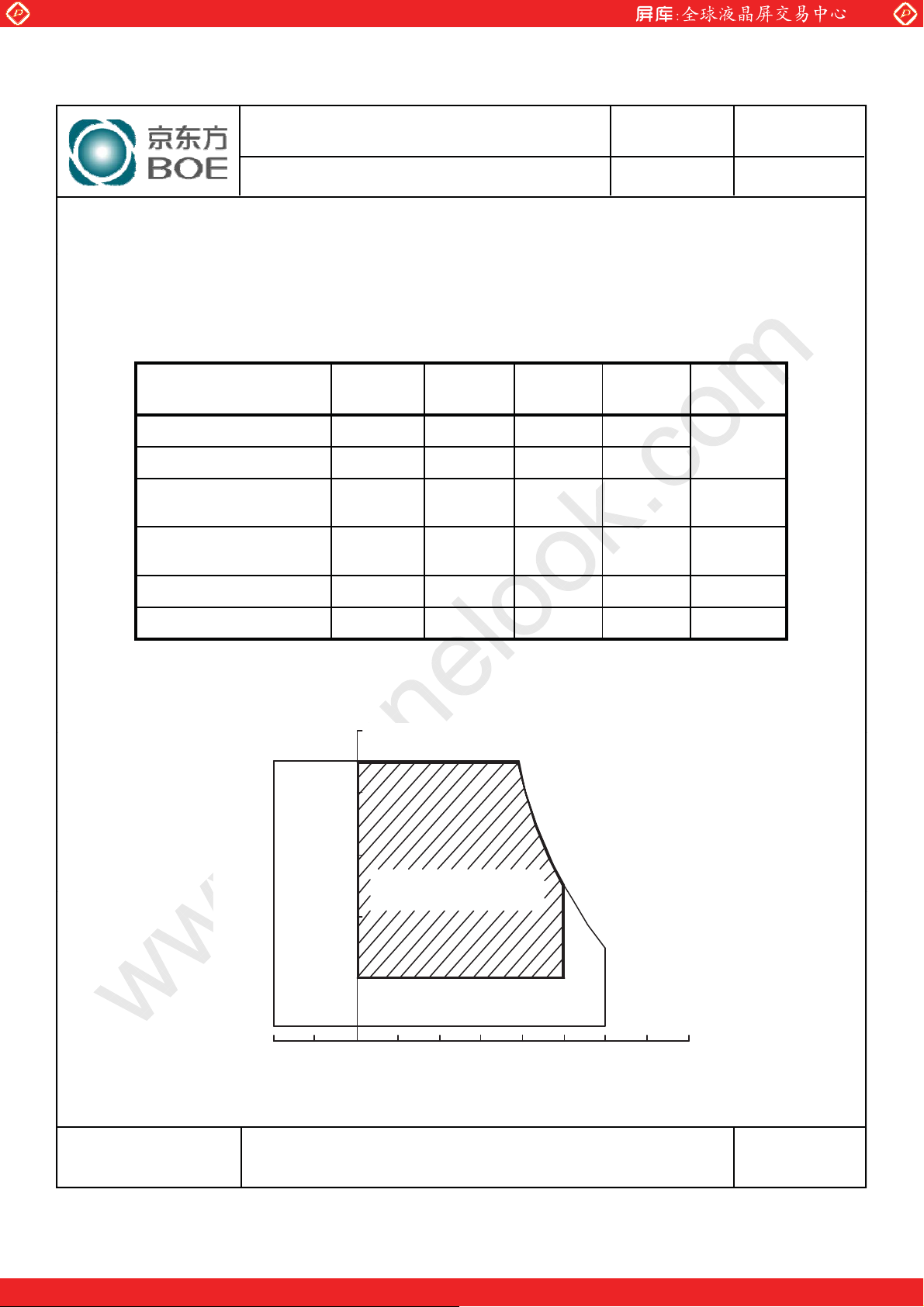
2.0 ABSOLUTE MAXIMUM RATINGS
ngs are maximum values which, if exceed, may cause faulty operation or
damage to the unit. The operational and non-operational maximum voltage and current
values are listed in Table 2.
< Table 2. Absolute Maximum Ratings>
Symbol Min. Max. Unit Remarks
Parameter
Power Supply Voltage V
Logic Supply Voltage V
LED Light Bar Current
Per Input Pin
LED Light Bar Voltage
Per Input Pin
IPIN - 105 mA
VPIN - 47.6 V
DD
IN
-0.3 6.0
VSS-0.3 VDD+0.3 V
[VSS=GND=0V]
V
ISSUE DATE
Mar. 26. 13’
Ta = 25 ć
Operating Temperature T
Storage Temperature T
OP
ST
0+50
-20 +60
ć
ć
Note : 1) Temperature and relative humidity range are shown in the figure below.
O
Wet bulb temperature should be 39
ڔڋ
ڐ
C max. and no condensation of water.
OZ`S`WP
O\WS\WP
O]WSZWP
1)
1)
SPEC. NUMBER
S
SPEC. TITLE
HR270WU3-300 Product Specification_Rev.P0
B2010-8002-O (3/3)
One step solution for LCD / PDP / OLED panel application: Datasheet, inventory and accessory!
PAGE
]
OF 30
A4(210 X 297)
www.panelook.com
Global LCD Panel Exchange Center
p
[
ധ
2
ć
]
ppp g
RF
DD
VIL100mV
Clock frequency =
MHz. Test Pattern of power supply current
www.panelook.com
PRODUCT GROUP
TFT- LCD PRODUCT
3.0 ELECTRICAL SPECIFICATIONS
3.1Electrical Specifications
< Table 3. Electrical specifications >
Parameter Min. Typ. Max. Unit Remarks
Power Supply Voltage V
Power Supply Current I
In-Rush Current I
Permissible In
High Level Differential Input
Threshold Voltage
Low Level Differential Input
Threshold Voltage
Differential input voltage |V
Differential input common mode voltage Vcm 1.0 1.2 1.5
ut Ripple VoltageV
DD
DD
RUSH
V
IH
V
IL
| 200 - 600 mV
ID
4.5 5.0 5.5 V
- 1000 1400 mA
- 2.0 3.0 A Note 2
- - 100 mV V
- - +100 mV
-100 - - mV
REV
Rev.P0
ISSUE DATE
Mar. 26. 13’
Ta =25
Note1
= 5.0V
V
=100mV,
IH
=-
Power Consumption
P
D
P
BL
P
total
-57W
- 18.8 20 W Note 3
- 23.8 27 W
Notes : 1. The supply voltage is measured and specified at the interface connector of LCM.
The current draw and power consumption specified is for VDD=5.0V, Frame rate=75Hz
92.9
a) Typ : Color Test
b) Max : Skip Subpixel255
2. Duration of rush current is about 2 ms and rising time of VDD is 520 s ρ 20 %
3. Calculated value for reference (Input pins*VPIN ശIPIN) excluding inverter loss.
SPEC. NUMBER
S
SPEC. TITLE
HR270WU3-300 Product Specification_Rev.P0
B2010-8002-O (3/3)
One step solution for LCD / PDP / OLED panel application: Datasheet, inventory and accessory!
PAGE
^
OF 30
A4(210 X 297)
www.panelook.com
Global LCD Panel Exchange Center
4.1O
r
www.panelook.com
PRODUCT GROUP
TFT- LCD PRODUCT
REV
Rev.P0
ISSUE DATE
Mar. 26. 13’
4.0 OPTICAL SPECIFICATION
verview
The test of Optical specifications shall be measured in a dark room (ambient luminance d 1 lux and temperature =
25r2ć) with the equipment of Luminance meter system (Goniometer system and TOPCONE BM-5) and test unit shall
be located at an approximate distance 50cm from the LCD surface at a viewing angle of and equal to 0q. We refer to
(=3) as the 3 o’clock direction (the “right”),
Ø=0
the 9 o’clock direction (“left”) and
(= 6 ) as the 6 o’clock direction (“bottom”). While scanning and/or Ø, the
Ø=270
center of the measuring spot on the Display surface shall stay fixed. The measurement shall be executed after 30
minutes warm-up period. VDD shall be 5.0V +/-10% at 25qC. Optimum viewing angle direction is 6 ’clock.
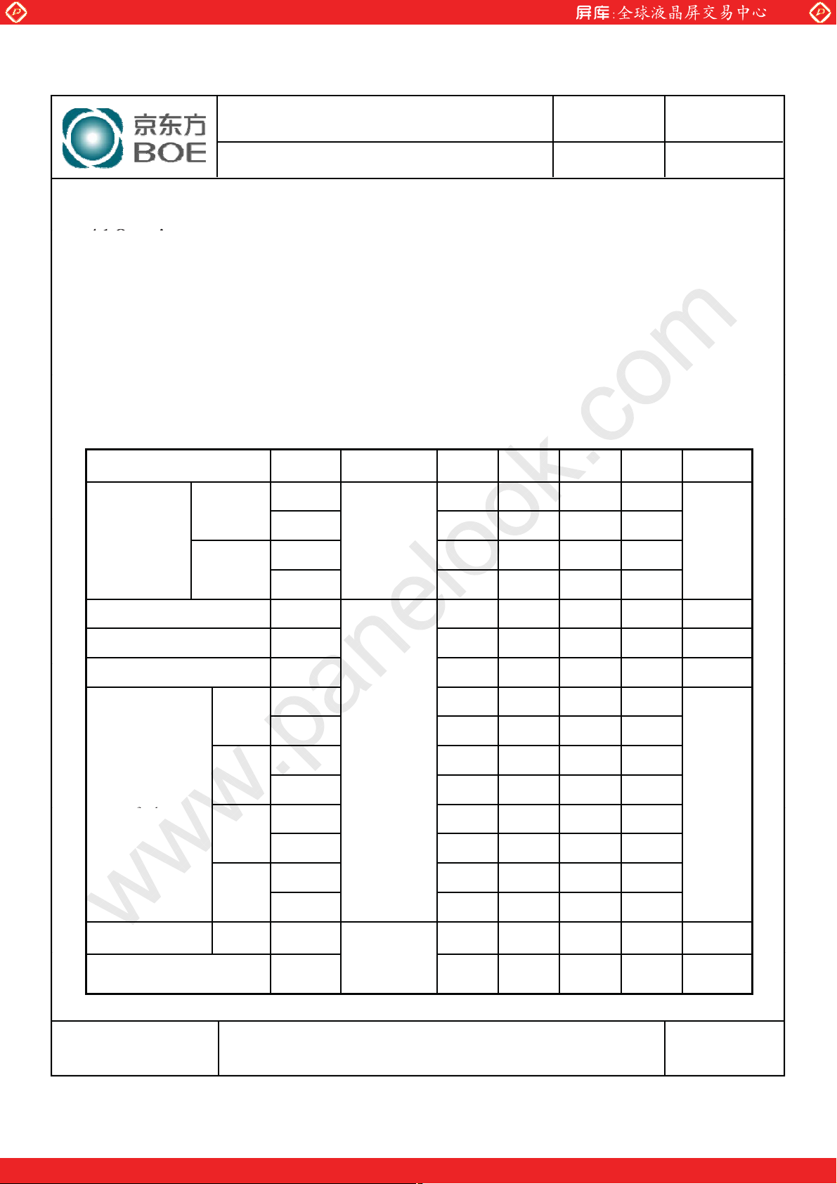
4.2 Optical Specifications
[VDD = 5.0V, Frame rate = 60Hz, Clock = 74.25MHz, IBL= 400mA, Ta =25ധ2 ć]
Parameter Symbol Condition Min. Typ. Max. Unit Remark
Horizontal
Viewing Angle
range
Vertical
3
9
12
6
(= 12) as the 12 o’clock direction (“upward”),
Ø=90
75 89 - Deg.
75 89 - Deg.
CR > 10 Note 1
70 89 - Deg.
70 89 - Deg.
Ø=180
(= 9) as
Luminance Contrast ratio CR 700 1000 Note 2
Transmittance 4.85% Note 3
White luminance uniformity Y 75 80 % Note 4
W
W
x
y
R
x
R
y
G
x
G
y
B
x
B
y
g
= 0q
(Center)
Normal
Viewing
Angle
White
Red
Reproduction
of colo
Green
Blue
Response
Time
Cross Talk CT - - 2.0 % Note 7
GTG T
0.283 0.313 0.343 -
0.299 0.329 0.359 -
0.615
0.298
0.273
0.588
0.118
0.030
0.645
0.328
0.303
0.618
0.148
0.060
14 20 ms Note 6
0.675 -
0.358 -
0.333 -
0.648 -
0.178 -
0.090 -
Note 5
(BOE BL)
SPEC. NUMBER
S
SPEC. TITLE
HR270WU3-300 Product Specification_Rev.P0
B2010-8002-O (3/3)
One step solution for LCD / PDP / OLED panel application: Datasheet, inventory and accessory!
PAGE
_
OF 30
A4(210 X 297)
www.panelook.com

Global LCD Panel Exchange Center
p
p,
y
y
ԩ
Y = ( Minimum Luminance of 9points / Maximum Luminance of 9points ) * 100
lumi
(Y
) of
ith all displ
www.panelook.com
PRODUCT GROUP
TFT- LCD PRODUCT
REV
Rev.P0
ISSUE DATE
Mar. 26. 13’
Note :
1. Viewing angle is the angle at which the contrast ratio is greater than 10. The viewing are
determined for the horizontal or 3, 9 o’clock direction and the vertical or 6, 12 o’clock
direction with respect to the optical axis which is normal to the LCD surface.
2. Contrast measurements shall be made at viewing angle of T= 0q and at the center of the LCD
surface. Luminance shall be measured with all
to the dark (black) state. (See FIGURE 1 shown in Appendix) Luminance Contrast Ratio (CR)
is defined mathematically.
CR =
Luminance when displaying a white raster
Luminance when displaying a black raster
3. Measurements shall be made at the center of the panel. The BLU is used b
Definition of Transmittance (T%) :
ixels in the view field set first to white, then
BOE.
Module is with white(L255) signal input
Luminance of LCD Module
Transmittance =
Luminance of BLU
Ý 100 %
4. The White luminance uniformity on LCD surface is then expressed as :
(See FIGURE 2 shown in Appendix).
5. The color chromaticity coordinates specified in Table 4. shall be calculated from the spectral
data measured with all pixels first in red, green, blue and white. Measurements shall be made
at the center of the panel.
6. Response time Tg is the average time required for display transition by switching the input
signal as below table and is based on Frame rate fV =60Hz to optimize.
Each time in below table is defined as Figure 3and shall be measured by switching the input
signal for “any level of gray(bright)”and “any level of gray(dark)”.
7. Cross-Talk of one area of the LCD surface by another shall be measured by comparing the
nance
luminance (Y
a 25mm diameter area, w
A
) of that same area when any adjacent area is driven dark. (See FIGURE 4
B
ay pixels set to a gray level, to the
shown in Appendix).
SPEC. NUMBER
S
SPEC. TITLE
HR270WU3-300 Product Specification_Rev.P0
B2010-8002-O (3/3)
One step solution for LCD / PDP / OLED panel application: Datasheet, inventory and accessory!
PAGE
`
OF 30
A4(210 X 297)
www.panelook.com
 Loading...