

BOE HR230WU1-100 Specification

PROPRIETARY NOTE
THIS SPECIFICATION IS THE PROPERTY OF BOE DTAND SHALL NOTBE
REPRODUCED OR COPIED WITHOUT THE WRITTEN PERMISSION OF BOE DTAND
MUST BE RETURNED TO BOE DTUPON ITS REQUEST
TITLE : HR230WU1-100
Preliminary ProductSpecification
Rev.P0
SPEC. NUMBER
S
B2010-8002-O(1/3)
BEIJING BOE Display TECHNOLOGY
PRODUCT GROUP
TFT-LCD
Rev.P0
ISSUE DATE
2012.5.23
PAGE
PAGE
1
OF 30
A4(210 X 297)
A4(210 X 297)
PRODUCT GROUP
TFT-LCD PRODUCT Rev.P0 May.23. 12’
REV
ISSUE DATE
REVISION HISTORY
REV. ECN No. DESCRIPTION OF CHANGES DATE PREPARED
Rev.P0 Initial Release May 23. 12’ TianChao
SPEC. NUMBER
S
B2010-8002-O(2/3)
SPEC. TITLE
HR230WU1-100 Preliminary Product Specification_Rev.P0
PAGE
2
OF 30
A4(210 X 297)
PRODUCT GROUP
REV
ISSUE DATE
TFT-LCD PRODUCT May. 23. 12’
Rev.P0
Contents
No. Item Page
1.0 General Description 4
2.0 Absolute Maximum Ratings 6
3.0 Electrical Specifications 7
4.0 Optical Specifications 8
5.0 Interface Connection 10
6.0 Signal Timing Specifications 13
7.0 Signal Timing Waveforms of Interface Signal 15
8.0 Input Signals, Display Colors & Gray Scale of Colors 17
9.0 Power Sequence 18
10.0 Mechanical Characteristics 19
11.0 Reliability Test 20
12.0 Handling& Cautions 21
13.0 Product Serial Number 22
14.0 Packing 23
15.0 Appendix 25
SPEC. NUMBER
S
B2010-8002-O(3/3)
SPEC. TITLE
HR230WU1-100 Preliminary Product Specification_Rev.P0
PAGE
3
OF 30
A4(210 X 297)
PRODUCT GROUP
Gate Driver
1920
×
1080
Connector (CN
Gate Driver
1920
×
1080
DC/DC
Connector (CN
REV
ISSUE DATE
TFT-LCD PRODUCT May. 23. 12’
Rev.P0
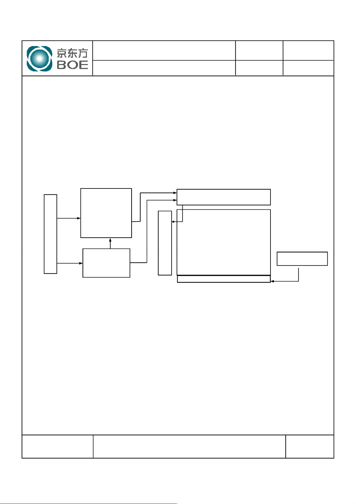
1.0 GENERAL DESCRIPTION
1.1 Introduction
HR230WU1-100 is a color active matrix TFT LCD module using amorphous silicon TFT's
(Thin Film Transistors) as an active switching devices. This module has a 23inch
diagonally measured active area with FHD resolutions (1920horizontal by 1080vertical
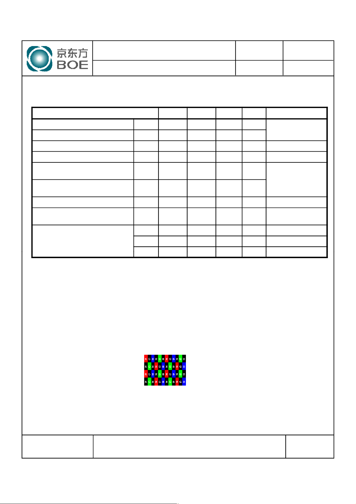
pixel array). Each pixel is divided into RED, GREEN, BLUE dots which are arranged in
vertical stripe and this module can display 16.7M colors. The TFT-LCD panel used for this
module is adapted for a low reflection and higher color type.
LVDS
Input
Signal
LVDS Rx
+
T/CON
+
Mini LVDSTx
Source Driver
TFT LCD Panel
VDD
1
)
1.2 Features
l LVDS Interface with 2 pixel / clock
l High-speed response
l 6-bit (Hi-FRC) color depth, display 16. 7Mcolors
l Incorporated edge type back-light (LED)
l sRGB
l High luminance and contrast ratio, low reflection and wide viewing angle
l DE (Data Enable) only
l RoHS/Halogen Free
l TCO 6.0 , E/S 6.0 compliant
l Gamma Correction
Gamma
Vcom
LED Lighting Bar
LED Connector
SPEC. NUMBER
S
B2010-8002-O(3/3)
SPEC. TITLE
HR230WU1-100 Preliminary Product Specification_Rev.P0
PAGE
4
OF 30
A4(210 X 297)
PRODUCT GROUP
REV
ISSUE DATE
TFT-LCD PRODUCT May. 23. 12’
1.3 Application
l Desktop Type of PC & Workstation Use
l Slim-Size Display for Stand-alone Monitor
l Display Terminals for Control System
l Monitors for Process Controller
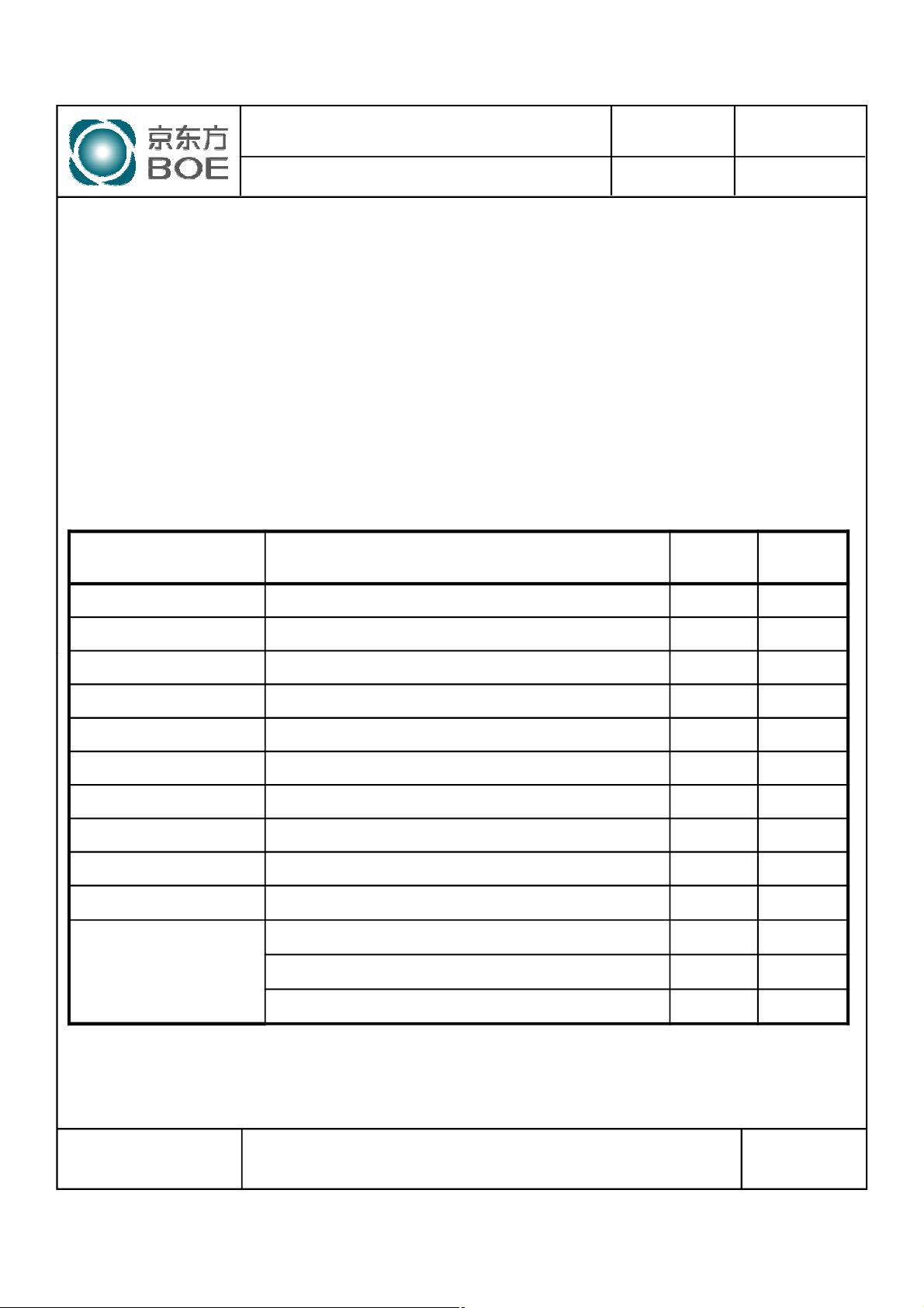
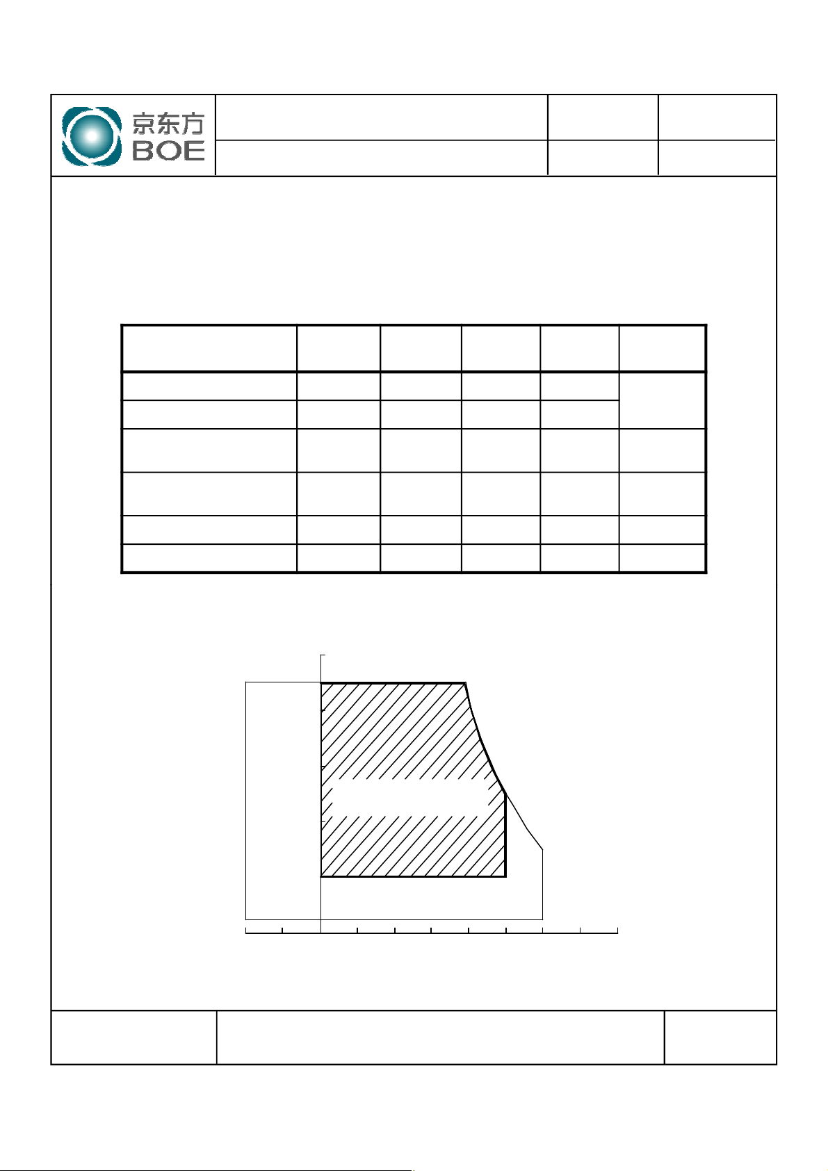
1.4 General Specification
The followings are general specifications at the model HR230WU1-100.
<Table 1. General Specifications>
Parameter Specification Unit
Active area
509.184(H) × 286.416(V)
Rev.P0
Remarks
mm
Number of pixels
Pixel pitch
Pixel arrangement RGB Vertical stripe
Display colors 16.7M colors
Display mode Normally Black
Dimensional outline
Weight TBD(Typ.) g
Surface Treatment
Back-light Lower edge side, 1-LED Lighting Bar type Note 1
Power Consumption
Notes : 1. LED Lighting Bar (4*input pins)
2. PLED=Input pins* VPIN×IPIN
1920(H) ×1080(V)
0.2652(H) ×0.2652(V)
533.2(H) × 312(V) × 10.5(D) typ.
Haze 25%, 3H
PD: 5.2W(max)
PBL: 16.3W (max) Note 2
P
:21.5(max)
total
pixels
mm
mm
SPEC. NUMBER
S
B2010-8002-O(3/3)
SPEC. TITLE
HR230WU1-100 Preliminary Product Specification_Rev.P0
PAGE
5
OF 30
A4(210 X 297)
PRODUCT GROUP
20
40
100
REV
ISSUE DATE
TFT-LCD PRODUCT May. 23. 12’
Rev.P0
2.0 ABSOLUTE MAXIMUM RATINGS
The followings are maximum values which, if exceed, may cause faulty operation or
damage to the unit. The operational and non-operational maximum voltage and current
values are listed in Table 2.
< Table 2. Absolute Maximum Ratings> [VSS=GND=0V]
Symbol Min. Max. Unit Remarks
Parameter
Power Supply Voltage V
Logic Supply Voltage V
LED Light Bar Current
Per Input Pin
LED Light Bar Voltage
Per Input Pin
Operating Temperature T
Storage Temperature T
IPIN - 80 mA
VPIN - 68 V
DD
IN
OP
ST
-0.3 6.0
VSS-0.3 VDD+0.3 V
0 +50
-20 +60
V
℃
℃
Ta = 25 ℃
1)
1)
Note : 1) Temperature and relative humidity range are shown in the figure below.
Wet bulb temperature should be 39 OCmax. and no condensation of water.
90
80
60
Operating Range
40
Relative Humidity (%RH)
20
Storage Range
5
0
Temperature (˚C)
(39,90)
(50,50)
(60,30)
60 80-20
SPEC. NUMBER
S
B2010-8002-O(3/3)
SPEC. TITLE
HR230WU1-100 Preliminary Product Specification_Rev.P0
PAGE
6
OF 30
A4(210 X 297)
PRODUCT GROUP
P
-
19.8
21.5
W
REV
ISSUE DATE
TFT-LCD PRODUCT May. 23. 12’
3.0 ELECTRICAL SPECIFICATIONS
3.1Electrical Specifications
< Table 3. Electrical specifications >
Parameter Min. Typ. Max. Unit Remarks
Power Supply Voltage V
Power Supply Current I
In-Rush Current I
Permissible Input Ripple Voltage V
High Level Differential Input
Threshold Voltage
Low Level Differential Input
Threshold Voltage
Differential input voltage |VID| 200 - 600 mV
Differential input common mode voltage Vcm 1.0 1.2 1.5
Power Consumption
DD
DD
RUSH
RF
V
IH
V
IL
P
D
P
BL
4.5 5.0 5.5 V
- 900 1100 mA
- 2.0 3.0 A Note 2
- - 100 mV VDD= 5.0V
- - +100 mV
-100 - - mV
- 4.5 5.2 W
- 15.3 16.3 W Note 3
Rev.P0
[Ta =25±2 ℃]
Note1
VIH=100mV,
VIL=-100mV
total
Notes : 1. The supply voltage is measured and specified at the interface connector of LCM.
The current draw and power consumption specified is for VDD=5.0V, Frame rate=75Hz
Clock frequency = 92.9 MHz. Test Pattern of power supply current
a) Typ : Color Test
b) Max : Skip Subpixel255
2. Duration of rush current is about 2 ms and rising time of VDD is 520 μs ± 20 %
3. Calculated value for reference (Input pins*VPIN ×IPIN) excluding inverter loss.
SPEC. NUMBER
S
B2010-8002-O(3/3)
SPEC. TITLE
HR230WU1-100 Preliminary Product Specification_Rev.P0
PAGE
7
OF 30
A4(210 X 297)
PRODUCT GROUP
25 ±2
℃
REV
ISSUE DATE
TFT-LCD PRODUCT May. 23. 12’
Rev.P0
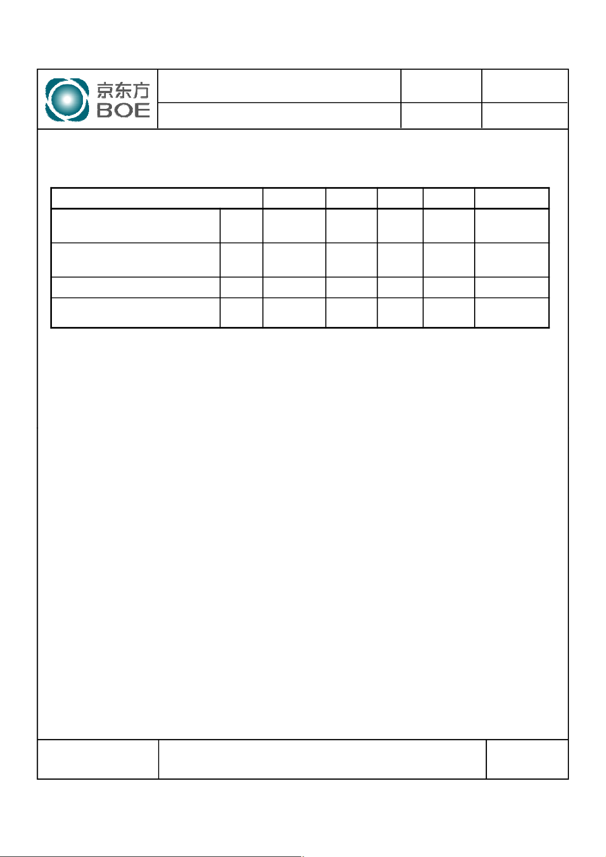
3.2 Backlight Unit
< Table 4. LED Backlight Unit >
Parameter Min. Typ. Max. Unit Remarks
LED Light Bar Input Voltage Per
Input Pin
LED Light Bar Input Current Per
Input Pin
LED Power Consumption P
LED Life-Time - 30,000 - Hrs Note 4
VPIN 60 64 68 V Duty 100%
IPIN - 60 - mA Note1,2,
BL
14.4
15.3 16.3
W Note 3
Note1: There are one light bar ,and the specified current is input LED chip 100% duty current
Note2: The sense current of each input pin is 60mA
Note3: PBL=4 Input pins*VPIN ×IPIN
Note4: The lifetime is determined as the time at which luminance of LED become 50% of the initial
brightness or not normal lighting at IPIN=60mA on condition of continuous operating at
SPEC. NUMBER
S
B2010-8002-O(3/3)
SPEC. TITLE
HR230WU1-100 Preliminary Product Specification_Rev.P0
PAGE
8
OF 30
A4(210 X 297)
PRODUCT GROUP
Θ
7089-
Deg.
Θ
6
7089-
Deg.
REV
ISSUE DATE
TFT-LCD PRODUCT May. 23. 12’
Rev.P0
4.0 OPTICAL SPECIFICATION
4.1 Overview
The test of Optical specifications shall be measured in a dark room (ambient luminance ≤ 1 lux andtemperature =
25±2℃) with the equipment of Luminance meter system (Goniometer system and TOPCONE BM-5) and test unit shall
be located at an approximate distance 50cm from the LCD surface at a viewing angle of θ and Φ equal to 0°. We refer to
θ
(=θ3) as the 3 o’clock direction (the “right”), θ
Ø=0
the 9 o’clock direction (“left”) and θ
(= θ6 ) as the 6 o’clock direction (“bottom”). While scanning θ and/or Ø, the
Ø=270
center of the measuring spot on the Display surface shall stay fixed. The measurement shall be executed after 30
minutes warm-up period. VDD shall be 5.0V +/-10% at 25°C. Optimum viewing angle direction is 6 ’clock.
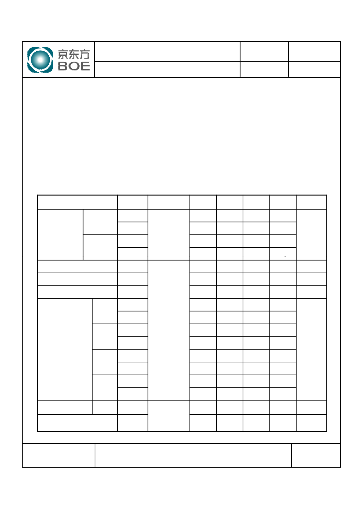
4.2 Optical Specifications
[VDD = 5.0V, Frame rate = 60Hz, Clock = 74.25MHz, IBL= = 200mA, Ta =25±2 ℃]
Parameter Symbol Condition Min. Typ. Max. Unit Remark
Θ
Horizontal
Viewing Angle
range
Vertical
3
Θ
9
Θ
12
(= θ12) as the 12 o’clock direction (“upward”), θ
Ø=90
75 89 - Deg.
75 89 - Deg.
CR > 10
70 89 - Deg.
Ø=180
(= θ9) as
Note 1
Luminance Contrast ratio CR
Luminance of White Y
White luminance uniformity ΔY 75 - % Note 4
White
Red
Reproduction
of color
Green
Blue
Response
Time
Cross Talk CT - - 2.0 % Note 7
GTG T
W
W
w
x
y
R
x
R
y
G
x
G
y
B
x
B
y
g
Θ = 0°
(Center)
Normal
Viewing
Angle
700 1000 Note 2
240 300 cd/m
0.283 0.313 0.343 -
0.299 0.329 0.359 -
TBD TBD TBD -
TBD TBD TBD -
TBD TBD TBD -
TBD TBD TBD -
TBD TBD TBD -
TBD TBD TBD -
14 20 ms Note 6
2
Note 3
Note 5
SPEC. NUMBER
S
B2010-8002-O(3/3)
SPEC. TITLE
HR230WU1-100 Preliminary Product Specification_Rev.P0
PAGE
9
OF 30
A4(210 X 297)
 Loading...