

Page 1

T100D
Z100 / Z300
Z500
Z700
v. 091709
Endurance® T100D Treadmill
User Manual
v. T100D-030513
Page 2

Table of Contents
I. REFERENCE DRAWINGS..............................
II. BEFORE YOU BEGIN.....................................
III. IMPORTANT SAFETY INSTRUCTIONS.........
IV. SAFETY GUIDELINES....................................
V. ASSEMBLY INSTRUCTIONS..........................
VI. ASSEMBLY STEPS........................................
VII. SETTING UP YOUR TREADMILL...................
VIII. OPERATING YOUR TREADMILL...................
IX. OPERATING THE CONSOLE.........................
X. PROGRAM FEATURES..................................
3
4
5
6 - 9
10 - 11
12 - 17
18
19
20 - 22
23 - 29
XI. TARGET HEART RATE ..................................
XII. CHEST STRAP OPERATION .........................
XIII. HEART RATE CONTROL OPERATION..........
XIV. GENERAL MAINTENANCE.............................
XV. TROUBLESHOOTING GUIDE........................
XVI. SETTING/SERVICE GUIDE............................
XVII. PARTS LIST....................................................
XVIII. EXPLODED VIEW DIAGRAM..........................
2
30 - 31
32
33
34 - 35
36
37 - 38
39 - 42
43
Page 3

Reference Drawings
Note: Due to continuing product improvements, specications and designs
are subject to change without notice.
Even though we have prepared this manual with extreme care, neither
the publisher nor the author can accept responsibility for any errors in,
or omission from, the information given.
3
Page 4
Before you Begin
Thank you for purchasing the Endurance T100 Treadmill.
To maximize your use of the equipment please study this Owner’s Manual thoroughly.
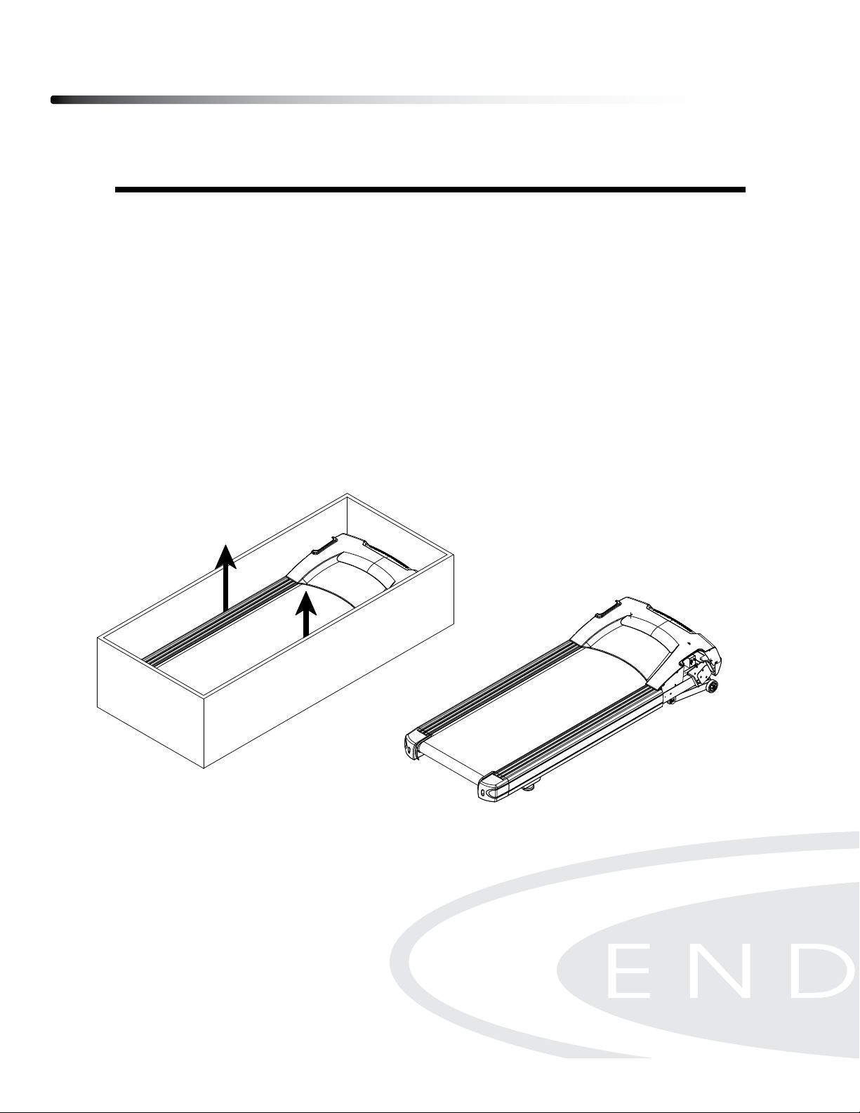
UNPACKING THE EQUIPMENT
The T100 is carefully tested and inspected before shipment. We have shipped the unit in
several pieces that require assembly. Ask for assistance during the assembly process.
CAUTION
Remove the Right and Left Uprights, Console and packing material carefully.
Hold the treadmill on each side and lift it out from the box carefully.
Position the treadmill on a at level surface.
Read the Owner’s Manual carefully before attempting to assemble the treadmill.
Endurance Equipment continually seeks ways to improve the performance, specications and product manuals in order to ensure that
only superior products are released from our factories. Please take the time to carefully read through this manual thoroughly.
Instructions contained in this document are not intended to cover all details or variations possible with Endurance Equipment, or to
cover every contingency that may be met in conjunction with installation, operation, maintenance or troubleshooting of the equipment.
Even though we have prepared this manual with extreme care, neither the publisher nor the author can accept responsibility for any
errors in, or omission from, the information given. Should additional information be required, or should situations arise that are not
covered by this manual, the matter should be directed to your local Endurance Equipment representative, or the Service Department
at Endurance Equipment in Forest Park, Illinois.
Any Questions?
Call (800) 556-3113
4
Page 5

Important Safety Instructions
Before beginning any tness program, you should obtain a complete physical examination
from your physician.
Il est conseille de subir un examen medical complet avant d’entreprendre tout programme d’exercise. Si vous
avez des etourdissements ou des faiblesses, arretez les exercices immediatement.
When using exercise equipment, you should always take basic precautions,
including the following:
Read all instructions before using the T100. These instructions are written to
ensure your safety and to protect the unit.
Do not allow children on or near the equipment.
Use the equipment only for its intended purpose as described in this guide.
Do not use accessory attachments that are not recommended by the manufacturer.
Such attachments might cause injuries.
Wear proper exercise clothing and shoes for your workout, no loose clothing.
Use care when getting on or off the unit.
Do not overexert yourself or work to exhaustion.
If you feel any pain or abnormal symptoms, stop your workout immediately and
consult your physician.
Never operate the unit after it has been dropped or damaged.
Return the equipment to a service center for examination and repair.
Never drop or insert objects into any opening in the equipment.
Always check the unit before each use.
Make sure that all fasteners are secure and in good working condition.
Do not use the equipment outdoors or near water.
PERSONAL SAFETY DURING ASSEMBLY
It is strongly recommended that a qualied dealer assemble the equipment.
Assistance is required.
Before beginning assembly, please take the time to read the instructions thoroughly.
Read each step in the assembly instructions and follow the steps in sequence.
Do not skip ahead. If you skip ahead, you may learn later that you have to
disassemble components and that you may have damaged the equipment.
Assemble and operate the T100 on a solid, level surface.
Locate the unit a few feet from the walls or furniture to provide easy access.
The T100 is designed for your enjoyment. By following these precautions and using common
sense, you will have many safe and pleasurable hours of healthful exercise with your
Endurance
After assembly, you should check all functions to ensure correct operation. If you experience
problems, rst recheck the assembly instructions to locate any possible errors made during
assembly. If you are unable to correct the problem, call the dealer from whom you purchased
the machine or call 1-800-556-3113 for the dealer nearest you.
T100.
5
Page 6

Safety Guidelines
Successful cardio training programs have one prominent feature in common...safety.
Cardio training has some inherent dangers, as do all physical activities.
The chance of injury can be greatly reduced or completely removed by using correct
running techniques, proper breathing, maintaining equipment in good working
condition, and by wearing the appropriate clothing.
any exercise program. This is especially important for individuals over the
age of 35, or persons with pre-existing health problems.
before you start. It is especially important to warm up the specic muscle
groups you are going to be using. This can be as simple as performing a
warm up set of high repetitions and light weight for each exercise.
Wearing comfortable athletic shoes with good support and loose tting,
breathable clothing will reduce the risk of injury.
importance for a safe cardio training program.
necessary that you familiarize yourself and all others with the proper
operation of this machine prior to use.
moving parts.
It is highly recommended that you consult your physician before beginning
Always warm up before starting a workout. Try to do a total body warm up
Always wear appropriate clothing and shoes when exercising.
Maintaining equipment in proper operating condition is of utmost
Read and study all warning labels on this machine. It is absolutely
Keep hands, limbs, loose clothing and long hair well out of the way of all
not allow the machine to be used until all parts are tightened or worn or
defective parts are repaired or replaced.
the treadmill on a at level surface with access to a 120VAC, 15Amp,
grounded outlet.
outlet on the end. the treadmill should be the only appliance in the electrical
circuit. do not attempt to disable the grounded plug by using improper
adapters, or in any way modify the cord set. a serious shock or re hazard
may result along with computer malfunctions.
Inspect the machine daily for loose or worn parts. If a problem is found do
To reduce the risk of burns, re, electric shock, or injury to persons, install
Do not use an extension cord unless it is 14awg or larger, with only one
6
Page 7
Safety Guidelines
ELECTRICAL SAFETY
WARNING!
NEVER use a RCD - Residual Current Device (U.S. ver.= GFCI) - wall outlet with this treadmill. As with
any appliance with a large motor, the RCD/GFCI will trip often. Route the power mains cord away from
any moving part of the treadmill including the elevation mechanism and transport wheels.
NEVER remove any cover without rst disconnecting AC power. If voltage varies by ten percent (10%)
or more, the performance of your treadmill may be affected. Such conditions are not covered under
your warranty. If you suspect the voltage is low, contact your local power company or a licensed
electrician for proper testing.
NEVER expose this treadmill to rain or moisture. This product is NOT designed for use outdoors, near
a pool or spa, or in any other high humidity environment. The temperature specication is 40 degrees
c, and humidity is 95%, non-condensing (no water drops forming on surfaces).
Circuit Breakers: Some circuit breakers used in homes are not rated for high inrush currents that can
occur when a treadmill is rst turned on or even during normal use. If your treadmill is tripping the circuit
breaker (even though it is the proper current rating and the treadmill is the only appliance on the circuit)
but the circuit breaker on the treadmill itself does not trip, you will need to replace the breaker with a
high inrush type. This is not a warranty defect. This is a condition we as a manufacture have no ability
to control. This part is available through most electrical supply stores
GROUNDING INSTRUCTION
This product must be grounded. If the treadmill’s electrical system should malfunction or breakdown
grounding provides a path of least resistance for electric current, reducing the risk of electric shock.
This product is equipped with a cord having an equipment-grounding plug. The plug must be plugged
into an appropriate outlet that is properly installed and grounded in accordance with all local codes and
ordinances.
DANGER - Improper connection of the equipment-grounding conductor can result in a risk of
electric shock. Check with a qualied electrician or serviceman if you are in doubt as to whether
the product is properly grounded. Do not modify the plug provided with the product if it will not
t the outlet; have a proper outlet installed by a qualied electrician.
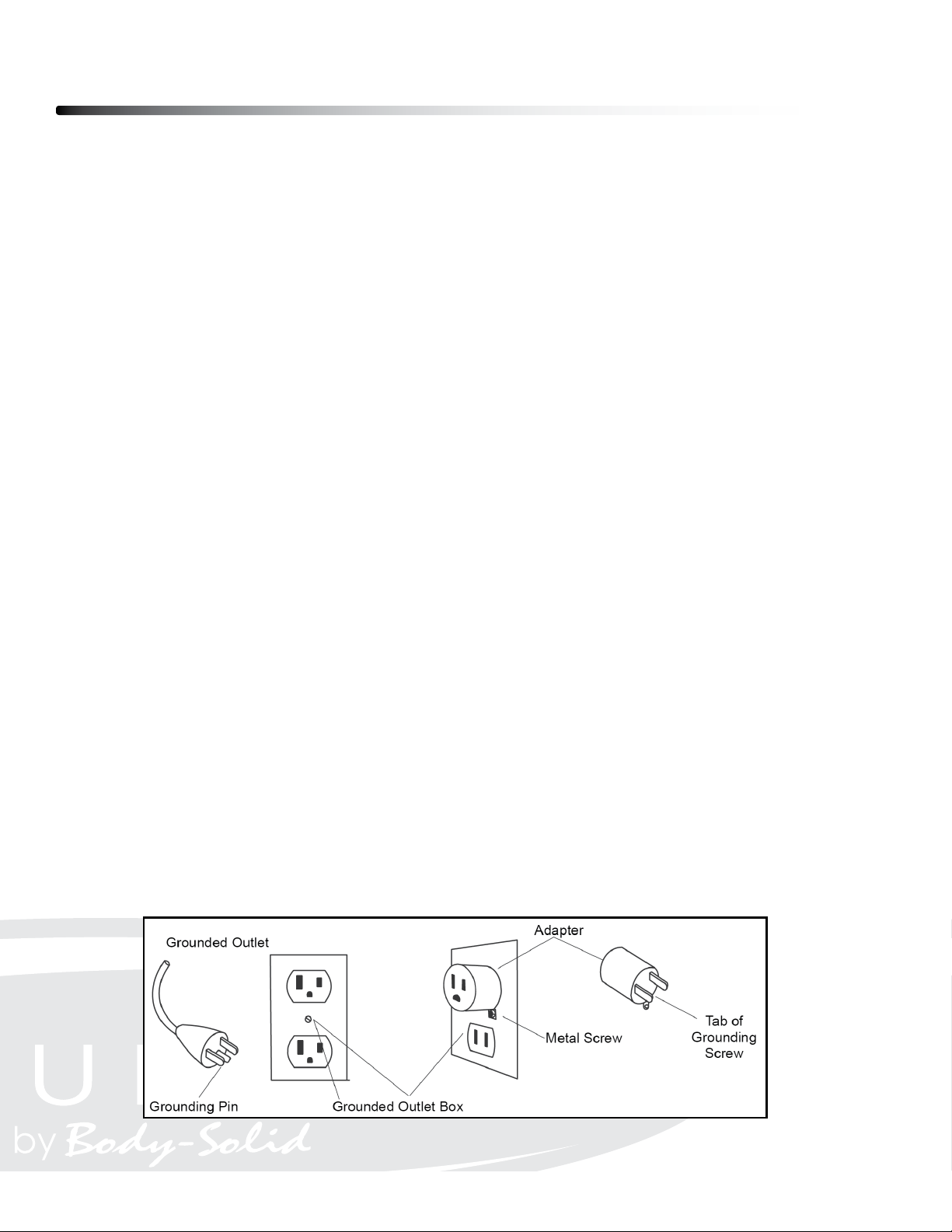
This product is for use on a nominal 120-volt circuit, and has a grounding plug that looks like the plug
illustrated below. A temporary adapter that looks like the adapter illustrated below may be used to
connect this plug to a 2-pole receptacle as shown below if a properly grounded outlet is not available.
The temporary adapter should be used only until a properly grounded outlet, (shown below) can be
installed by a qualied electrician. The green colored rigid ear-lug, or the like, extending from the
adapter, must be connected to a permanent ground such as a properly grounded outlet box cover.
Whenever the adapter is used, it must be held in place by a metal screw.
7
Page 8

Safety Guidelines
This exercise equipment is designed and built for optimum safety for home use.
However, certain precautions always apply whenever you operate any exercise
equipment.
Be sure to read the entire manual before assembly and operation of this machine.
Also, please note the following safety precautions.
MECHANICAL SAFETY
Inspect the equipment prior to exercising to ensure that all nuts and bolts are
fully tightened before each use.
Replace any defective components immediately and/or keep the equipment out
of use until repair.
Do not use attachments not recommended by the manufacturer.
Never drop or insert an object into any opening.
Only one person may use the treadmill at a time.
Never activate the treadmill when someone is standing on the belt.
APPROPRIATE ATTIRE
Always wear appropriate clothing.
Do not wear loose clothing that might catch on any part of this treadmill.
Always wear non-slippery shoes while working with the treadmill.
Do not wear shoes with heels or leather soles.
Check the soles of your shoes and remove any dirt and embedded stones.
CHILDREN AND PETS
Most exercise equipment is not recommended for small children.
Children should not use the equipment unless they are under strict adult supervision.
To ensure safety, keep young children off the treadmill at all times.
Exercise equipment has many moving parts.
In the interest of safety, keep others (especially children and pets) at a safe distance
while you exercise.
FCC WARNING - POSSIBLE RADIO/TELEVISION INTERFERENCE
NOTE: This equipment has been tested and found to comply with Part 15 of the FCC rules. These limits are designed to
provide reasonable protection against harmful interference in a residential installation. Any changes or modications not
expressly approved by the party responsible for the compliance could void the user’s authority to operate the equipment.
This equipment generates, uses and can radiate radio frequency energy and, if not installed and used in accordance
with the instructions, may cause harmful interference to radio communications. However, there is no guarantee that the
interference will not occur in a particular installation.
If this equipment does cause harmful radio interference to radio or television reception, which can be determined by
turning the equipment off and on, you are encouraged to try to correct the interference by one or more of the following
measures:
Class R (Residential): Private or non-commercial use
• Reorient or relocate the receiving antenna
• Increase space between the equipment
• Plug the equipment into two electrical outlet located on separate circuits
• Consult an exercise equipment dealer or an experienced radio/TV technician for help
8
Page 9

Safety Guidelines
IMPORTANT OPERATION INSTRUCTIONS
● NEVER operate this treadmill without reading and completely understanding the
results of any operational change you request from the computer.
● Understand that changes in speed and incline do not occur immediately. Set your
desired speed on the computer console and release the adjustment key. The
computer will obey the command gradually.
● NEVER use your treadmill during an electrical storm. Surges may occur in your
household power supply that could damage treadmill components.
● Use caution while participating in other activities while walking on your treadmill;
such as watching television, reading, etc. These distractions may cause you to lose
balance or stray from walking in the center of the belt; which may result in serious
injury.
● NEVER mount or dismount the treadmill while the belt is moving. treadmills start
with at a very low speed and it is unnecessary to straddle the belt during start up.
Simply standing on the belt during slow acceleration is proper after you have
learned to operate the unit.Always hold on to a handrail or hand bar while making
control changes (incline, speed, etc.).
Do not use excessive pressure on console control keys. They are precision set to
function properly with little nger pressure. Pushing harder is not going to make the
unit go faster or slower. If you feel the buttons are not functioning properly with
normal pressure contact your dealer.
SAFETY TETHER CORD
A safety tether cord is provided with this unit. It is a simple magnetic design that should be
used at all times. It is for your safety should you fall or move too far back on the tread-belt.
Pulling this safety tether cord will stop tread-belt movement.
To Use:
1. Place the magnet into position on the console control head. Your treadmill will not start
and operate without this.
2. Fasten the plastic clip onto your clothing securely to assure good holding power.
Note: The magnet has strong enough power to minimize accidental, unexpected
stopping. The clip should be attached securely to make certain it does not come off. Be
familiar with its function and limitations. The treadmill will stop, depending on speed, with a
one to two step coast anytime the magnet is pulled off the console. Use the red Stop / Pause
switch in normal operation.
9
Page 10
Assembly Instructions
Professional installers are highly recommended!
However, if you acquire the appropriate tools, obtain assistance, and follow the
assembly steps sequentially, the process will take time, but is fairly easy.
ASSEMBLY TIPS
Read all “NOTES” on each page before beginning each step.
While you may be able to assemble the T100 using the illustrations only, important safety
notes and other tips are included in the text.
Some pieces may have extra holes that you will not use. Use only those holes indicated in
the instructions and illustrations.
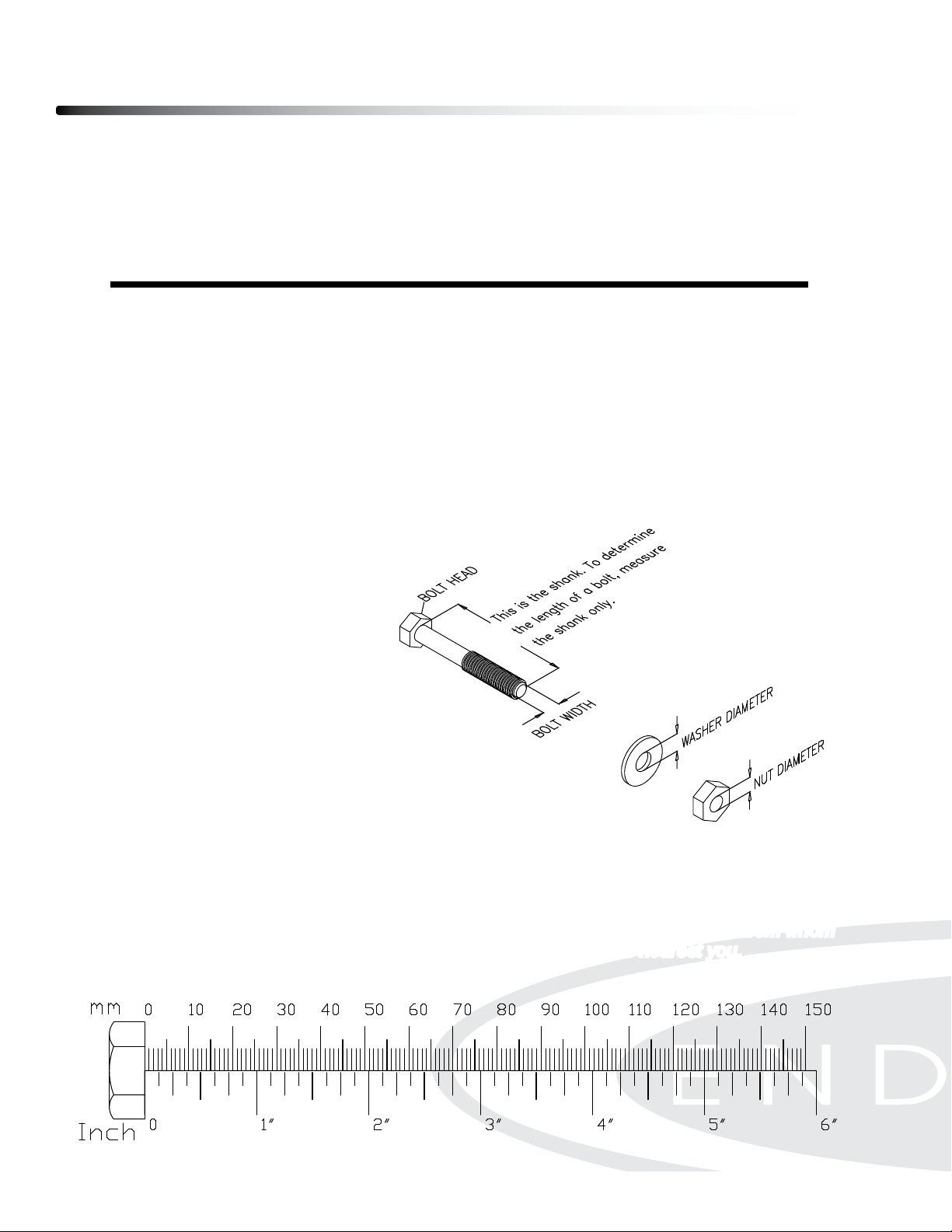
NOTE: To nd out the length of a particular bolt, measure its shank (the long, narrow part
beneath the head).
Refer to the following diagram:
Do not fully tighten bolts until instructed to do so.
NOTE: After assembly, you should check all functions to ensure correct operation. If you
experience problems, rst recheck the assembly instructions to locate any possible errors
made during assembly. If you are unable to correct the problem, call the dealer from whom
you purchased the machine or call 1-800-556-3113 for the dealer nearest you.
10
Page 11
Hardware Pack Check List
Assembly Pack Check List
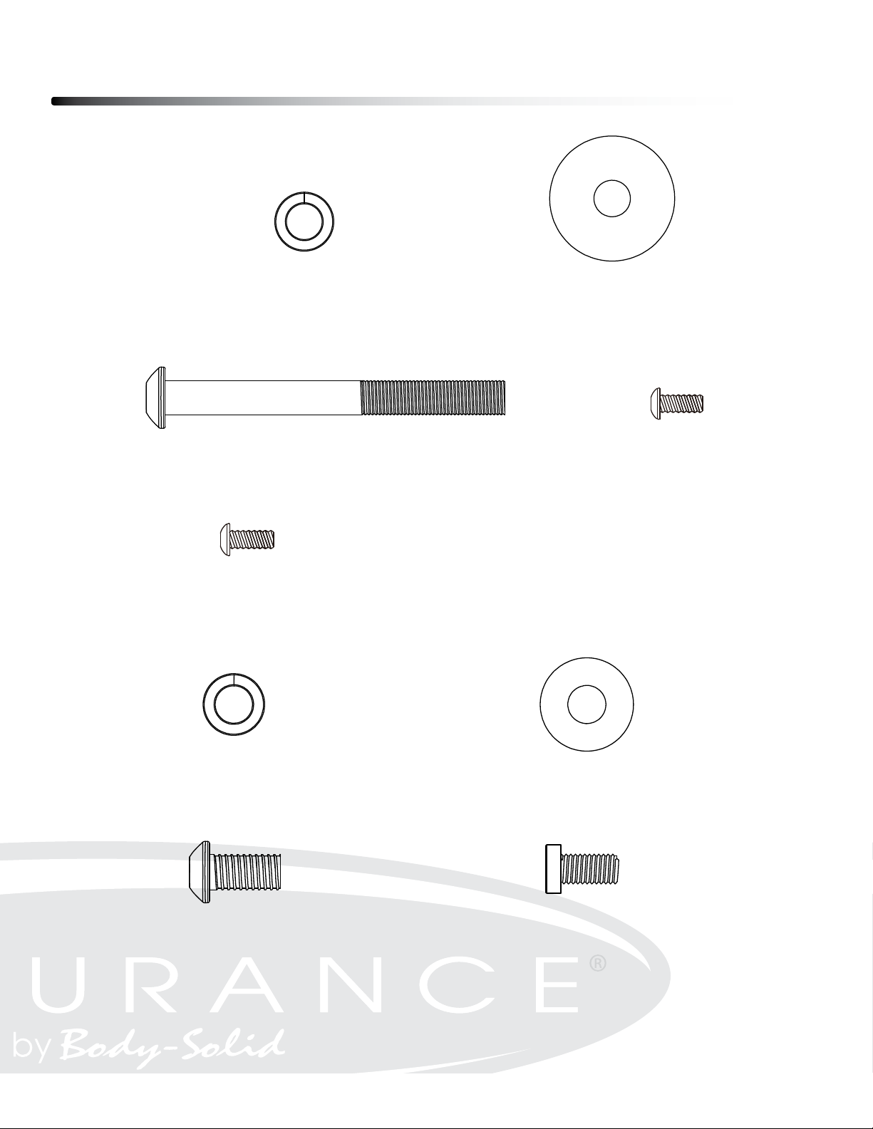
Step1
#117 - 3/8" x16.5 x2.0T x4H
Split Washer (6 pcs)
#116 -ψ3/8" x 35 x 2T
Flat Washer (6 pcs)
Step2
Step3
#144 - 3/8”-16 x 3”
Button Head Socket Bolt (6 pcs)
#134 - M5 x 12mm
Phillips Head Screw (4 pcs)
#117 - 3/8" x16.5 x2.0T x4H
Split Washer (6 pcs)
#134 - M5 x 12mm
Phillips Head Screw (4 pcs)
#125 -ψ3/8" x25 x2T
Flat Washer (6 pcs)
#145 – 3/8”-16 x3/4”
Button Head Socket Bolt (6 pcs)
#146 – M8 x1.25x12mm
Socket Head Cap Bolt (6 pcs)
11
Page 12

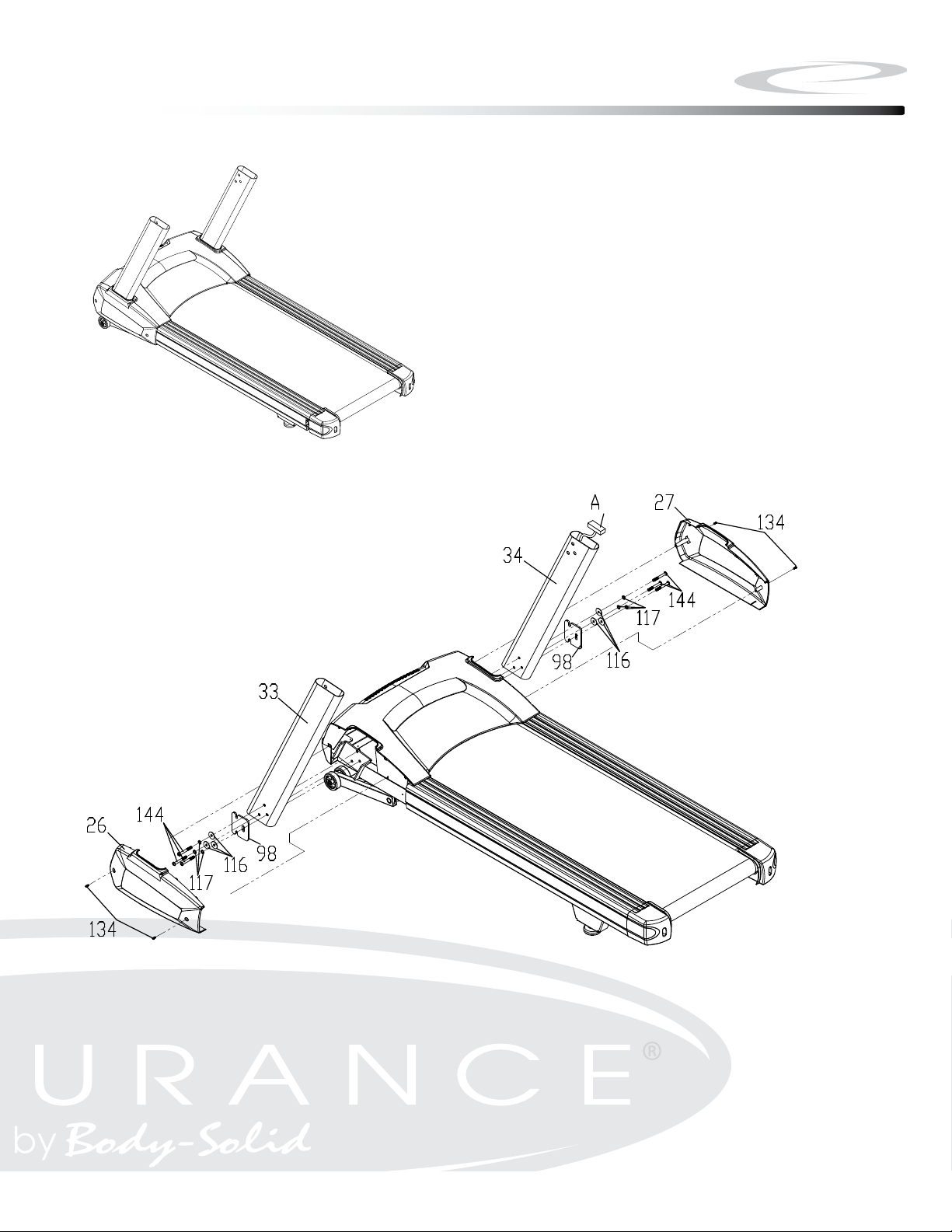
Step 1
Be careful to assemble all components
in the sequence they are presented.
A. Attach Right Upright (#34) to Frame Base using:
One Retaining Plate (#98)
Three 3/8”-16 x 3” Button Head Socket Bolts (#144)
Three 3/8” Lock Washers (#117)
Three 3/8” Flat Washers (#116)
Note: The right upright (34) is with preinstalled lower computer cable A. To install
uprights on the frame base, special care must be taken not to pinch the cable
between the upright and frame base.
B. Attach Left Upright (#33) to Frame Base using:
One Retaining Plate (#98)
Three 3/8”-16 x 3” Button Head Socket Bolts (#144)
Three 3/8” Lock Washers (#117)
Three 3/8” Flat Washers (#116)
C. Attach Motor Base Caps (#26 ) to Frame Base using
Four M5x12mm Phillips Head Screws (#134)
12
Page 13
Above shows STEP 1 assembled and completed.
Step 1
13
Page 14

Step 2
Be careful to assemble all components
in the sequence they are presented.
A. Connect Upper Computer Cable B (#41), Hand Pulse Assembly C & D (#37
& #38), Touch Pad/Backlit Cable E(#43) and Groud Wire F (#35) to the board on
on back of the console (#28)
B. Attach Console Assembly (#28) to Console Support (#5) using:
Four M5x12mm Phillips Head Screws (#134)
14
Page 15

Above shows STEP 2 assembled and completed.
Step 2
15
Page 16

Step 3
Be careful to assemble all components
in the sequence they are presented.
A. Attached the console to Mounting Brackets (#3 & #4) using:
Six M8x12mm Socket Head Cap Screws (#146)
B. Connect Upper Computer Cable F (#41) to Lower Computer Cable A (#42)
C. Attach the Mounting Brackets (#3 & #4) to the Uprights using:
Six 3/8”-16 x 3/4” Button Head Socket Bolts (#145)
Six 3/8” Lock Washer (#117)
Six 3/8” Flat Washer (#125)
16
Page 17

Above shows STEP 3 assembled and completed.
Step 3
17
Page 18

Setting up your Treadmill
PLACEMENT IN YOUR HOME
To make exercise a desirable daily activity for you, the treadmill should be placed in a
comfortable and attractive setting. This treadmill is designed to use minimal oor space and
to t nicely in your home.
Do not place or operate the treadmill outdoors.
Do not place the treadmill near water or in a high moisture content environment.
Make sure the power cord is not in the path of heavy trafc.
It is highly recommended to place a dedicated treadmill mat beneath your treadmill.
A dedicated mat provides superior stability and rmness for a proper workout.
Locate the treadmill at least 4 feet from walls or furniture.
Occasionally, after extended use, you will nd a ne black dust below your treadmill. This
is normal wear and DOES NOT mean there is anything wrong with your treadmill. This dust
can be easily removed with a vacuum cleaner. If you wish to prevent this dust from getting
on your oor or carpet, place a dedicated treadmill mat beneath your treadmill.
LEVELING THE BASE
It is important that you place the treadmill on a rm level surface. If the ground is uneven, you
may level the treadmill with levelers located under the deck. Make sure the back of the deck
is not higher than the front. If adjustments are to be made, check to see if the leverage feet,
as shown below, touch the ground rmly. If there is a gap, turn the leverage foot
counterclockwise to eliminate the gap.
Make sure the running deck is level to the ground. If the deck is positioned so that you are
running downhill, it will cause premature damage to the electronic system
18
Page 19

Operating your Treadmill
TURN POWER ON
The On/Off switch for the treadmill is located next to the power supply cord receptacle on the
front of the treadmill. Insert the power supply cord into the receptacle and ip the switch to
the “ON” position.
MOVING THE TREADMILL
This treadmill is easy to move around safely.
To move the treadmill:
1. Turn the power switch off.
2. Unplug the power cord.
3. Lift the rear of the treadmill to a comfortable angle.
4. Simply roll the treadmill on its front two wheels to the desired location.
5. Gently lower the rear of the treadmill to ground level.
STORE YOUR TREADMILL
Please follow these safety precautions, especially if you have children at home.
We suggest to take the following precautions when storing your treadmill.
1. When you nish your workout, turn the power switch to the off position.
2. Remove the plug from the outlet.
3. Remove the safety key.
It is imperative that the safety key is removed and kept away from children.
19
Page 20

Operating the Console
Getting familiar with the control panel
■ Console
Getting Started:
Power the treadmill on by plugging it into an appropriate wall outlet, then turn on the power
switch located at the front of the treadmill below the motor hood. Ensure that the safety key
is installed, as the treadmill will not power on without it.
When the power is turned on, all the lights on the display will light for a short time. Then the
Time and Distance windows will display Odometer readings for a short time. The Time win-
dow will show how many hours the treadmill has been in use and the Distance window will
show how many Kilometers (or Miles if the treadmill is set to English readings; see
maintenance for changing settings) the treadmill has gone. A message will be displayed
showing the current software version. The treadmill will then enter idle mode, which is the
starting point for operation.
20
Page 21

Operating the Console
Quick-Start Operation:
• Press and release the START key to begin belt movement at 0.5 mph/0.8 kph, then
adjust to the desired speed using the FAST keys.
• To slow tread-belt using the SLOW key to the desired speed.
• To stop the tread-belt press and release STOP key.
TREADMILL FEATURES:
Pause/Stop/Reset:
• When the treadmill is running the pause feature may be utilized by pressing the STOP
key once. This will slowly decelerate the tread-belt to a stop. The incline stays at that level
and Time, Distance and Calorie readings will hold while the unit is in the pause mode. After
5 minutes the display will reset and return to the start up screen.
• To resume your exercise with previous speed and incline settings when in Pause
mode, press the START key.
• Pressing the STOP key twice will end the program and a workout summary will be
displayed. If the STOP button is pressed a third time, the console will return to the idle mode
(start up) screen.
• If the STOP button is held down for more than 3 seconds the console will reset.
• When you are setting data, such as age and time, for a program pressing the STOP
key will allow you to go back one step for each key press.
Incline:
• Incline may be adjusted anytime after the belt starts moving.
• Press and hold the UP or DOWN keys to achieve desired level of effort.
Dot Matrix Center Display:
Ten rows of dots indicate each level of a workout in manual mode. The dots are only to show
an approximate level (speed/incline) of effort. They do not necessarily indicate a specic
value - only an approximate percent to compare levels of intensity. In Manual Operation the
Speed / Incline dot matrix window will build a prole “picture” as values are changed during
a workout. There are twenty-four columns, indicating time. The 24 columns are divided into
1/24th of the total time of the program. When the time is counting up from zero (as in quick
start) each column represents 1 minute.
21
Page 22

Operating the Console
Next to the Dot Matrix window are three LED lights labeled: Track, Speed and Incline,
along with a DISPLAY button. When the Track LED is lit the dot matrix displays the Track
prole, when the Speed LED is lit the Dot matrix displays the Speed prole and when the
Incline LED is lit the Dot Matrix displays the Incline prole. You may change the Dot Matrix
prole view by pressing the DISPLAY button. After scrolling through the three proles the
Dot matrix will automatically scroll through the three displays showing each one for four
seconds. The LED associated with each prole will blink while that view is displayed. One
more press of the DISPLAY button will return you to the Track prole.
1/4 Mile Track:
The 1/4 mile track (0.4km) will be displayed around the dot matrix window. The ashing dot
indicates your progress. In the center of the track there is a lap counter for reference.
Heart Rate Feature:
The Pulse (Heart Rate) window will display your current heart rate in beats per minute
during the workout. You must use both left and right stainless steel sensors to pick up your
pulse. Pulse values are displayed anytime the computer is receiving a Grip Pulse signal.
You may use the Grip Pulse feature while in Heart Rate Control. The TREADMILL will also
pick up wireless heart rate transmitters that are Polar compatible.
Heart Rate Bar Graph:
Displays a graphical representation of your heart rate as a percentage of your maximum
heart rate. When you enter your age during programming, the console will calculate your
maximum heart rate then light up the graph to show the percent of maximum heart rate
you are currently achieving.
Message Window Display:
Displays messages that help guide you through the programming process. During a program the message window displays your workout data.
To Turn Treadmill Off:
The display will automatically turn off (go to sleep) after 30 minutes of inactivity. This function is called sleep mode. In sleep mode, the treadmill will power down most everything except for a minimum of circuitry for detecting key presses and the safety key so it will start
up again if these are activated. There is only a tiny amount of current used in sleep mode
(about the same as your TV when it is turned off) and it is perfectly ne to leave the main
power switch on in sleep mode.
Of course you may also remove the safety key or turn off the main power switch to power
down the treadmill.
22
Page 23

Program Features
The New TREADMILL offers twelve preset programs, HILL, FAT BURN, CARDIO, CALORIE, INTERVAL, STRENGTH, 5K RUN, 10K RUN, HR 1, HR 2, CUSTOM, a Gerkin protocol
based Fitness Test and one Manual program.
Preset Features:
To choose and start preset program:
• Select a program then press the ENTER key to begin customizing the program with
your personal data, or just press the start key to begin the program with the
default settings.
• After selecting a program and pressing ENTER to set your personal data, the Time
window will blink with the default value of 20 minutes. You may use any of the
UP/ DOWN/ FAST/ SLOW keys to adjust the time. After adjusting the time, press ENTER.
(Note: Except for program CALORIE, You may press START at any time during the
programming to begin with only settings you have modied at that point).
• The INCLINE window will now be blinking a value indicating your Age. Entering the
correct Age will affect the Heart rate bar graph accuracy and also needed for the HR programs. Use the UP/ DOWN/ FAST/ SLOW keys to adjust, you can also use numeric keypads
0~9 on the console to make adjustments, and then press ENTER.
• The INCLINE window will now be blinking a value indicating your Bodyweight.
Entering your correct bodyweight affects the Kcal readout accuracy. Use UP/ DOWN/ FAST/
SLOW keys to adjust, you can also use numeric keypads 0~9 on the console to make adjustments, and then press ENTER.
• The SPEED window will now be blinking, showing the preset top speed of the selected
program. Use UP/ DOWN/ FAST/ SLOW keys or numeric keys to adjust, you can also use
numeric keypads 0~9 on the console to make adjustments, and then press ENTER. Each
program has various speed changes throughout; this allows you to limit the highest speed
the program will attain during your workout.
• Now press the START key to begin your workout.
23
Page 24

Program Features
Preset programs speed and incline settings
The preset program speed and incline levels are shown in the chart below. The Speed numbers shown in
the chart indicate a percentage of the top speed of the program. For instance, the first Speed setting for
P1 (Program 1, HILL) shows the number 20. This means that this segment of the program will have a
speed that is 20% of the top speed for the program (The user sets the top speed in the procedure above).
If the user sets the top speed to 10 mph, then the first segment will be 2 mph. You will notice that segment
12 shows 100 which means, the speed will be set to 100% of 10 mph or simply 10 mph.
30 40 50 60 60 70 70 70 80 70 70 80 80 60 70 80 80 70 70 70
30 40 50 60 60 70 80
30 40 50 50 60 80 90
30 40 50 60 60 70 70 80 80 90 90 90
• There will be a 3 minute warm-up to begin. You can press the START button to
bypass this and go straight to the workout. During the warm-up the clock will count down
from 3 minutes. ( 5K RUN, 10K RUN, HR 1, HR 2, CUSTOM and the manual program don’t
have a warm-up mode.)
Preset programs speed and incline settings
The preset program speed and incline levels are shown in the chart below. The Speed numbers shown in the chart indicate a percentage of the top speed of the program. For instance,
the rst Speed setting for P1 (Program 1, HILL) shows the number 20. This means that this
segment of the program will have a speed that is 20% of the top speed for the program
(The user sets the top speed in the procedure above). If the user sets the top speed to 10
mph, then the rst segment will be 2 mph. You will notice that segment 12 shows 100 which
means, the speed will be set to 100% of 10 mph or simply 10 mph.
Prog
P1
P2
P3
P4
P5
P6
SEG Warm up 1 2 3 4 5 6 7 8 9 10 11 12 13 14 15 16 17 18 19 20 21 22 23 24
2
Speed
Incline 0 0 0 0 1 2 3 3 4 3 3 4 4 5 3 3 4 3 3 4 4 5 4 3 1 1 0 0 0 0
Speed
Incline 0 0 0 0 1 2 3 3 3 4 5 3 3 4 4 3 3 2 2 3 4 5 6 4 2 1 0 0 0 0
Speed
Incline 0 0 0 0 1 1 1 2 2 3 2 2 3 3 1 2 3 3 2 2 4 4 2 3 1 1 0 0 0 0
Speed
Incline 0 0 0 0 1 2 3 5 6 2 3 5 6 7 2 3 7 2 3 8 2 3 5 4 3 1 0 0 0 0
Speed
Incline 0 0 0 0 0 0 0 0 0 0 0 0 0 0 0 0 0 0 0 0 0 0 0 0 0 0 0 0 0 0
Speed
Incline 0 0 0 1 1 1 4 4 4 4 4 4 5 5 5 5 5 5 5 5 3 3 3 3 3 1 1 0 0 0
30 40 50 60 60 70 70 70 80 80 70 80 80 100 100 70 80 80 70 70 80 80 70 60 60 50 40 30 20
0
2
30 40 50 60 60 70 80 100 100 100 100 100 100 100 100 100 100 100 100 100 100 100 80 70 60 50 40 30 20
0
2
0
2
0
2
0
2
0
100 60 60 70 80 100 60 70 100 60 70 100 60 70 80 70 60 60 50 40 30 20
100 70 100 70 100 70 100 70 100 70 100 70 100 90 80 70 60 50 50 40 30 20
100 100 100 100 100 100 100 100 100 100 90 80 60 50 40 30 20
100 70 80 60 60 50 40 30 20
P1= HILL P2= FAT BURN P3= CARDIO P4= INTERVAL P5 = CALORIE P6=STRENGTH
Cool
down
CALORIE Program:
• Press program button “CALORIE” to perform the program. The message window
shows ”PRESS ENTER TO MODIFY”
• .Press “ENTER” button, the message window shows ”ADJUST AGE THEN PRESS
ENTER” with the INCLINE window is blinking. After the age is set, press “ENTER” to con-
tinue.
24
Page 25

Program Features
• Message window is showing ”ADJUST BODY WEIGHT THEN PRESS ENTER” now
with INCLINE window is blinking. After the weight is set, press “ENTER” button to continue.
• Message window is showing ”ADJUST TARGET CALORIES BURN THEN PRESS
ENTER” and INCLINE window is blinking. After setting target CALORIE, press “ENTER”
button to continue.
• Message window now is showing ”ADJUST MAX. SPEED THEN PRESS ENTER”
with SPEED window is blinking. After max. speed is set, press “ENTER” button to continue.
• Message window now is showing . ”ADJUST MAX. INCLINE THEN PRESS ENTER”
and INCLINE window is blinking. After max. incline is set then press “ENTER” button,
message window shows ”PROGRAM TIME”. The console then automatically calculates the
time needed and shows it on TIME window.
• Now message window is showing ”PRESS START TO BEGIN WORKOUT OR
ENTER TO MODIFY”. Press “START” button to start the workout.
Custom Program:
• Selecting the Custom program button, the message window shows ”PRESS ENTER
TO MODIFY OR START TO BEGIN WORKOUT”. You can either press “ENTER” button or
press “START” button to begin the workout. When you press “ENTER” button, dot matrix
window will show U1 and ashing. In the mean time, the message window will show ”PRESS
1 OR 2 TO SELECT THEN PRESS ENTER”. You can choose U1 or U2 for setting by
pressing “1” or “2” button, then “ENTER” button. Note that the dot matrix display portion will
light a single row of dots at the bottom (Unless there is a previously saved program).
• After pressing “ENTER” button, the message window will show ”ADJUST TIME THEN
PRESS ENTER” with TIME window is blinking. Use the UP/DOWN/FAST/SLOW or numeric
keypads to adjust and set the program for the desired time. Press the ENTER key. This is a
must to continue even if the time is not adjusted.
• Now the message window is showing ”ADJUST AGE THEN PRESS ENTER”. The
Incline window will now be blinking a value indicating your Age. Entering the correct Age will
affect the Heart rate bar graph accuracy. Use UP/DOWN/FAST/SLOW keys or numeric keys
to adjust and then press ENTER key.
• Now the message window is showing ”ADJUST SPEED THEN PRESS ENTER”. The
rst speed setting column (segment) will now be blinking and SPEED is blinking too. To set
the speed value you want, use FAST / SLOW keys to adjust the speed to your desired
effort level for the rst segment then press ENTER. The second column will now be blinking.
Note that the previous segment value has been carried over to the new segment. Repeat the
above process until all segments have been programmed.
25
Page 26

Program Features
• Now the message window is showing ”ADJUST INCLINE THEN PRESS ENTER”.
The rst column will be blinking again and INCLINE window is blinking too. The console is
now ready for the incline settings. To set the incline value you want, Use UP/DOWN/FAST/
SLOW keysto adjust the incline to your desired effort level for the rst segment then press
“ENTER”.Repeat the same process used to set the speed values for programming the
segments for incline.
• When the setting is completed, the message window will show ”PRESS START TO
BEGIN WORKOUT OR ENTER TO MODIFY” .Press the START button to begin the workout and also save the program to memory.
5 Km and 10Km Run:
This program automatically sets a 5K or 10K (5 or 10 kilometer) distance as your goal. The
track display will show one loop that is the equivalent of 5 or 10 kilometers and the Distance window will also show 5K or 10K to start. When the program begins the Distance will
count down; once it reaches zero the program ends.
*Please note that the Speed readout is in MPH if the console is not set to Metric readings.
26
Page 27

Program Features
5 Km and 10Km Run:
This program automatically sets a 5K or 10K (5 or 10 kilometer) distance as your goal. The track
display will show one loop that is the equivalent of 5 or 10 kilometers and the Distance window will
also show 5K or 10K to start. When the program begins the Distance will count down; once it
reaches zero the program ends.
*Please note that the Speed readout is in MPH if the console is not set to Metric readings.
Fitness Test:
The fitness test is based on the Gerkin protocol, also known as the fireman’s protocol, and is a
submax Vo2 (volume of oxygen) test. The test will increase speed and elevation alternately until
you reach 85% of your Target heart rate (THR). THR=(220-AGE)x0.85 The time it takes for you to
reach THR determines the test score as shown in the chart below.
Fitness Test:
The tness test is based on the Gerkin protocol, also known as the reman’s protocol, and
is a submax Vo2 (volume of oxygen) test. The test will increase speed and elevation alternately until you reach 85% of your Target heart rate (THR). THR=(220-AGE)x0.85 The
time it takes for you to reach THR determines the test score as shown in the chart below.
Stage Time Speed Grade VO2 Max
1 0 to 1:00 4.5mph 0% 31.15
2.1 1:15 4.5mph 2% 32.55
2.2 1:30 4.5mph 2% 33.6
2.3 1:45 4.5mph 2% 34.65
2.4 2:00 4.5mph 2% 35.35
3.1 2:15 5.0mph 2% 37.45
3.2 2:30 5.0mph 2% 39.55
3.3 2:45 5.0mph 2% 41.3
3.4 3:00 5.0mph 2% 43.4
4.1 3:15 5.0mph 4% 44.1
4.2 3:30 5.0mph 4% 45.15
4.3 3:45 5.0mph 4% 46.2
4.4 4:00 5.0mph 4% 46.5
5.1 4:15 5.5mph 4% 48.6
5.2 4:30 5.5mph 4% 50
5.3 4:45 5.5mph 4% 51.4
5.4 5:00 5.5mph 4% 52.8
6.1 5:15 5.5mph 6% 53.9
6.2 5:30 5.5mph 6% 54.9
6.3 5:45 5.5mph 6% 56
6.4 6:00 5.5mph 6% 57
7.1 6:15 6.0mph 6% 57.7
7.2 6:30 6.0mph 6% 58.8
7.3 6:45 6.0mph 6% 60.2
7.4 7:00 6.0mph 6% 61.2
8.1 7:15 6.0mph 8% 62.3
8.2 7:30 6.0mph 8% 63.3
8.3 7:45 6.0mph 8% 64
8.4 8:00 6.0mph 8% 65
9.1 8:15 6.5mph 8% 66.5
9.2 8:30 6.5mph 8% 68.2
9.3 8:45 6.5mph 8% 69
9.4 9:00 6.5mph 8% 70.7
10.1 9:15 6.5mph 10% 72.1
10.2 9:30 6.5mph 10% 73.1
10.3 9:45 6.5mph 10% 73.8
10.4 10:00 6.5mph 10% 74.9
11.1 10:15 7.0mph 10% 76.3
11.2 10:30 7.0mph 10% 77.7
11.3 10:45 7.0mph 10% 79.1
11.4 11:00 7.0mph 10% 80
27
Page 28

Program Features
Before the test:
• Make sure you are in good health; check with your physician before performing any
exercise if you are over the age of 35 or persons with pre-existing health conditions.
• Make sure you have warmed up and stretched before taking the test.
• Do not take in caffeine before the test.
• If using the hand pulse sensors hold the hand grips gently, do not tense up.
Fitness test programming:
1. Press the Fitness-test button and press ENTER.
2. The message window will ask you to enter your Age. You may adjust the age setting
by using UP/ DOWN/ FAST/ SLOW keys or numeric keys, with the adjustment shown in
the Incline window, then press the ENTER key to accept the new number and proceed on
to the next screen.
3. You are now asked to enter your Weight. You may adjust the weight setting by using
UP/ DOWN/ FAST/ SLOW keys or numeric keys, with the adjustment shown in the INCLINE window, then press ENTER to continue.
4. Now press START to begin the test.
During the test:
• The console must be receiving a steady heart rate for the test to begin. You may
use the hand pulse sensors or wear a heart rate chest strap transmitter.
• The test will start with a 3 minute warm-up at 5kph (3mph) before the actual test
begins.
• The data shown during the test is:
a. Time indicates total elapsed time
b. Incline in percent grade
c. Distance in Miles or Kilometers depending on preset parameter.
d. Speed in MPH or KPH depending on preset parameter.
e. Target Heart Rate and Actual Heart Rate are shown in the message window.
After the test:
• Cool down for about one to three minutes.
• Take note of your score because the console will automatically return to the start-up
mode after a few minutes.
28
Page 29

Program Features
What your score means:
VO2max for male and fitted female
18-25 26-35 36-45 46-55 56-65 65+
years
excellent >60 >56 >51 >45 >41 >37
good 52-60 49-56 43-51 39-45 36-41 33-37
above
average 47-51
average 42-46 40-42 35-38 32-35 30-31 26-28
below
average 37-41
poor 30-36 30-34 26-30 25-28 22-25 20-21
very poor <30 <30 <26 <25 <22 <20
old
years
old
43-48 39-42 35-38 32-35 29-32
35-39 31-34 29-31 26-29 22-25
years
old
years
old
years
old
years
old
VO2max for female and non-fitted male
18-25 26-35 36-45 46-55 56-65 65+
years
excellent
good 47-56 45-52 38-45 34-40 32-37 28-32
above
average 42-46
average 38-41 35-38 31-33 28-30 25-27 22-24
below
average 33-37
poor 28-32 26-30 22-26 20-24 18-21 17-18
very poor <28 <26 <22 <20 <18 <17
old
56 52 45 40 37 32
years
old
39-44 34-37 31-33 28-31 25-27
31-34 27-30 25-27 22-24 19-22
years
old
years
old
years
old
years
old
29
Page 30

Target Heart Rate
To obtain the greatest cardiovascular benets from your exercise workout, it is important to
work within your target heart rate zone. The American Heart Association (AHA) denes this
target as 60% -75% percent of the Maximum Heart Rate.
The Maximum Heart Rate may be roughly calculated by subtracting the user’s age from
220.
The Maximum Heart Rate and aerobic capacity naturally decreases as the user ages. This
may vary from one person to another, but use this number to nd your approximate effective
target zone. For example, the Maximum Heart Rate for an average 40 year-old is 180 bpm.
The target heart rate zone is 60%-75% of 180 or 108-135 bpm. See the FITNESS SAFETY
section.
Before beginning a workout, check the normal resting heart rate. The user can place their
ngers lightly against the neck or wrist over the main artery. After nding the pulse, count the
number of beats in 10 seconds. Multiply the number of beats by six to determine your pulse
rate per minute. It is recommend to take a heart rate measurement at rest, after warming up,
during the workout and two minutes into cooling down after the workout, to accurately track
progress as it relates to better tness.
During your rst several months of exercising, the AHA recommends aiming for the lower
part of the target heart rate zone - 60%, then gradually progressing up to 75%. According to
the AHA, exercising above 75% of the Maximum Heart Rate may be too strenuous unless
the user is in top physical condition. Exercising below 60% of the maximum will result in
minimal cardiovascular conditioning.
CHECK YOUR PULSE RECOVERY RATE
If your pulse is over 100 bpm ve minutes after stopping exercising, or if it’s higher than normal the morning after exercising, the user’s exertion may have been too strenuous for their
current tness level. Rest and reduce the intensity next time.
CAUTION!
The target value used in HR-1 and HR-2 programs is a suggestion only for normal, healthy
individuals. Do not exceed your limits! You may not be able to obtain your chosen target. If
in question, enter a higher age value that will set a lower target goal.
30
Page 31

Target Heart Rate
Fitness saFety
The Heart Rate chart indicates average rate zones for dierent ages. A variety of
dierent factors (including medication, emotional state, temperature and other
conditions) can aect the target heart rate zone that is best for you. Your physician or
health care professional can help you determine the exercise intensity that is
appropriate for your age and condition.
(MHR) = Maximum Heart Rate
(THR) = Target Heart Rate
220 - Age = Maximum Heart Rate (MHZ)
MHZ x .60 = 60% of your Maximum Heart Rate.
MHZ x .75 = 75% of your Maximum Heart Rate.
For example, if you are 30 years old, your calculations will be as follows:
220 - 30 = 190
190 x .60 = 114 (Low End or 60% of MHZ)
190 x .75 = 142 (High End or 75% of MHZ)
30 Year-Old (THR) Target Heart Rate would be 114-142
Maximum Heart Rate (MHR) Calculation
Heart Rate Training Zone Chart
31
Page 32

Chest Strap Operation (Optional)
Your Endurance® T100 Treadmill has the capability to determine Heart Rate with the use
of a Heart Rate Chest Strap. It is available as an optional accessory for use with your unit
depending on the Endurance® model purchased. In all Heart Rate Control programs, the
console only accepts the heart rate signal from the chest strap transmitter while the pulse
grip heart rate function is disabled. The requirement to wear the chest strap is due to the
superior accuracy of a chest strap transmitter compared to the pulse grip sensors.
It is suggested for the Chest Strap Transmitter that you position the transmitter as close to
your heart as possible, against the skin, 1-2 inches below the pectoral muscles. For best
results, moisten the back of the transmitter for better contact.
SAFETY PRECAUTIONS AND TIPS FOR CHEST STRAP
1. It is the owner’s responsibility to ensure that all users of this unit have read the Owner’s
Manual and are familiar with warnings and safety precautions.
2. Do not place chest strap near devices that generate large magnetic elds. TV sets,
electric motors, radios, and high voltage power lines can affect the transmitter’s performance. These items can interfere with the heart rate signal and possibly affect the heart
rate readings on the console.
3. Handle the Chest Strap with care. Dropping the transmitter might cause damage that
could void the warranty.
4. Do not use the chest strap if you have a cardiac pacemaker or if your are taking medi-
cations for a heart condition. Medication or electrical pulses from the pacemaker can
interfere with accurate heart rate readings.
5. Do not bend the strips inside the chest strap. This can cause the chest strap to loose
conductivity.
6. The chest strap has batteries that need to be replaced periodically. A faulty battery can
cause inaccurate reading.
32
Page 33

Heart Rate Control Operation
How the Heart Rate Control Program Works:
Heart Rate Control (HRC) uses your treadmill’s incline system to adjust your heart rate. Increases and decreases in elevation affect heart rate much more efciently than changes in
speed alone. The HRC program automatically changes elevation gradually to achieve the
programmed target heart rate.
Selecting a Heart Rate Control Program:
You have the option, during the setup mode, to choose either the Weight Control (HR-1) program or the Cardiovascular (HR-2) program. The Weight Control program will maintain your
heart rate at 70% of your Maximum Heart Rate. The Cardiovascular program will maintain
your heart rate at 90% of your Maximum Heart Rate. Your Maximum Heart Rate is based
upon a formula that subtracts your age from a constant of 220. Your HR setting is automatically calculated during the setup mode when you enter your age.
Heart Rate Control Program
You must receive a strong / steady value in heart rate window or the program will not
start.
• Press Program HR button to enter heart rate control program.
• Now the window will show ”PRESS ENTER TO MODIFY OR START TO BEGIN
WORKOUT”. You can either press “ENTER” button for setting or press “START” button to
execute the program.
• .When “ENTER” button is pressed, the message window shows ”PRESS 1 OR 2 TO
SELECT THEN PRESS ENTER”. At the same time, the dot matrix window is showing “1”
and you can press numeric keypad 1 or 2 and then “ENTER” button..
• Now message window is showing ”ADJUST TIME THEN PRESS ENTER” with TIME
window is blinking. Use UP/DOWN/FAST/SLOW keys or numeric keys to adjust. After setting time, press “ENTER” button again.
• Now message window is showing ”ADJUST AGE THEN PRESS ENTER” with INCLINE window is blinking. Use UP/DOWN/FAST/SLOW keys or numeric keys to adjust.
Adjusting age will change THR value. (as the THR formula described above).After age is
set, press “ENTER” button again.
• Now message window is showing ”ADJUST BODY WEIGHT THEN PRESS ENTER”
with INCLINE window is blinking. Use UP/DOWN/FAST/SLOW keys or numeric keys to adjust. After the weight is set, press “ENTER” button again..
• Now message window is showing ”ADJUST HEART RATE THEN PRESS ENTER”
with SPEED window is blinking. Use UP/DOWN/FAST/SLOW keys or numeric keys to adjust. After the target heart rate value is set, Press “ENTER” button again.
• The message window is then showing ”PRESS START TO BEGIN WORKOUT OR
ENTER TO MODIFY”. .Press “START” button to begin the workout.
Note: When the message window is showing ”CHECK PULSE”, there is no pulse signal received and the program can not be performed. Please check and make sure that
Heart Rate strap functions normally.
33
Page 34

General Maintenace
Belt and Bed - Your treadmill uses a very high-efficient low-friction bed. Performance is
maximized when the bed is kept as clean as possible. Use a soft, damp cloth or paper towel to
wipe the edge of the belt and the area between the belt edge and frame. Also reach as far as
practical directly under the belt edge. This should be done once a month to extend belt and bed
life. Use water only - no cleaners or abrasives. A mild soap and water solution along with a nylon
scrub brush will clean the top of the textured belt. Allow the belt to dry before using.
Belt Dust - This occurs during normal break-in or until the belt stabilizes. Wiping excess off with
a damp cloth will minimize buildup.
General Cleaning - Dirt, dust, and pet hair can block air inlets and accumulate on the running
belt. On a monthly basis: vacuum underneath your treadmill to prevent buildup. Once a year, you
should remove the black motor hood and vacuum out dirt that may accumulate. UNPLUG
POWER CORD BEFORE THIS TASK.
BELT ADJUSTMENTS:
Tread-belt Tension Adjustment - Adjustment must be made from the rear roller. The
adjustment bolts are located at the end of the step rails in the end caps, as noted in diagram
below.
General Maintenance
Adjustment
Adjustment
Belt and Bed - Your treadmill uses a very high-efcient low-friction bed. Performance is
maximized when the bed is kept as clean as possible. Use a soft, damp cloth or paper
towel to wipe the edge of the belt and the area between the belt edge and frame. Also
reach as far as practical directly under the belt edge. This should be done once a month to
extend belt and bed life. Use water only - no cleaners or abrasives. A mild soap and water
solution along with a nylon scrub brush will clean the top of the textured belt. Allow the belt
to dry before using.
Belt Dust - This occurs during normal break-in or until the belt stabilizes. Wiping excess
off with a damp cloth will minimize buildup.
General Cleaning - Dirt, dust, and pet hair can block air inlets and accumulate on the running belt. On a monthly basis: vacuum underneath your treadmill to prevent buildup. Once
a year, you should remove the black motor hood and vacuum out dirt that may accumulate. UNPLUG POWER CORD BEFORE THIS TASK.
BELT ADJUSTMENTS:
Tread-belt Tension Adjustment - Adjustment must be made from the rear roller. The adjustment bolts are located at the end of the step rails in the end caps, as noted in diagram
below.
Tracking / Tension
Note: Adjustment is through small hole in the end cap.
Tighten the rear roller bolts only enough to prevent slippage at the front roller. Turn both
tread-belt tension adjustment bolts in increments of 1/4 turn each and inspect for proper
tension by walking on the belt at a low speed, making sure the belt does not slip. Keep
tensioning the bolts until the belt stops slipping.
• If you feel the belt is tight enough, but it still slips, the problem may be a
loose Motor drive belt under the front cover.
DO NOT OVERTIGHTEN – Over tightening will cause belt damage and premature bearing
failure.
Tracking / Tension
34
Page 35

General Maintenance
TREADBELT TRACKING ADJUSTMENT:
The performance of your treadmill is dependent on the frame running on a reasonably
level surface. If the frame is not level, the front and back roller cannot run parallel, and
constant belt adjustment may be necessary.
The treadmill is designed to keep the tread-belt reasonably centered while in use. It is
normal for some belts to drift near one side while the belt is running with no one on it. After
a few minutes of use, the tread-belt should have a tendency to center itself. If, during use,
the belt continues to move toward one side, adjustments are necessary.
TO SET TREADBELT TRACKING:
A 10 mm Allen wrench is provided to adjust the rear roller. Make tracking adjustments from
the left side only. Set belt speed at approximately 3 to 5 kph.
Remember, a small adjustment can make a dramatic difference!
Turn the bolt clockwise to move the belt to the right. Turn the bolt only a 1/4 turn and wait
a few minutes for the belt to adjust itself. Continue to make 1/4 rotation turns until the belt
stabilizes in the center of the running deck.
The belt may require periodic tracking adjustment depending on use and walking/running
characteristics. Some users will affect tracking differently. Expect to make adjustments as
required to center the tread-belt. Adjustments will become less of a maintenance concern
as the belt is used. Proper belt tracking is an owner responsibility common with all
treadmills.
ATTENTION:
DAMAGE TO THE RUNNING BELT RESULTING FROM IMPROPER TRACKING /
TENSION ADJUSTMENTS IS NOT COVERED UNDER THE WARRANTY.
35
Page 36

Troubleshooting Guide
Before contacting your dealer for aid, please review the following information. It may save you
both time and expense. This list includes common problems that may not be covered under the
treadmill’s warranty.
ore weight
from the belt
re on
moves, then the
Service Checklist - Diagnosis Guide
PROBLEM SOLUTION/CAUSE
Display does not light 1) Tether cord not in position.
2) Circuit breaker on front grill tripped. Push circuit breaker in
until it locks.
3) Plug is disconnected. Make sure plug is firmly pushed into
120 VAC wall outlet.
4) Breaker panel circuit breaker may be tripped.
5) Treadmill defect. Contact your dealer.
Tread-belt does not stay centered The user may be walking while favoring or putting m
on either the left or right foot. If this walking pattern is natural,
track the belt slightly off-center to the side opposite
movement.
Treadmill belt hesitates when walked/run on See General Maintenance section on Tread-belt Tension.
Motor drive belt may be loose.
Motor is not responsive after pressing start 1) If the belt moves, but stops after a short time and the
display shows “Low Speed”, run calibration (See procedu
next page).
2) If you press start and the belt never
display shows Low Speed, contact service.
Treadmill will only achieve approximately
7 mph but shows higher speed on display This indicates motor should be receiving power to
operate. Low AC voltage to treadmill. Do not use an extension
cord. If an extension cord is required it should be as short as
possible and heavy duty 16 gauge minimum. Low household
voltage. Contact an electrician or your dealer. A minimum of
100 volt AC current, 60 hz is required.
Treadmill trips on board 15 amp circuit High belt/deck friction. See General Maintenance section.
Computer shuts off when console is
touched (on a cold day) while walking/running Treadmill may not be grounded. Static electricity is “crashing”
the computer.
House circuit breaker trips, but not the Need to replace the house breaker with a “High
treadmill circuit breaker. inrush current” type breaker.
36
Page 37

Setting/Service Guide
Calibration procedure:
1) Remove the safety key
2) Press and hold down the INCLINE and SPEED buttons with one hand and replace
the safety key with the other. Continue to hold both keys until the window displays
“FACTORY SETTING”, then press the ENTER key.
3) You will now be able to set the display to show English or Metric settings. To do this,
press UP/DOWN or FAST/SLOW keys to show which you want, then press
ENTER.
4) Make sure the wheel size diameter is 2.98 then press ENTER.
5) Adjust the maximum speed (if needed) to 12.0mph or 20.0kph and then press
ENTER.
6) Adjust the minimum speed (if needed) to 0.5mph or 0.8kph and then press ENTER.
7) Message Windows will show “INCLINE STEPS “. Adjust the maximum elevation (if
needed) to 15 and then press ENTER.
8) Message Windows will show “CALIBRATION ON“. Press START to begin
calibration. The process is automatic; the speed will start up without warning, so do
not stand on the belt. After nishing calibration, it automatically returns to IDLE
MODE.
Adjusting the speed sensor:
If the calibration does not pass you may need to check the speed sensor alignment.
1) Release motor cover screws (screws are not necessarily taken apart) and remove
the motor cover hood.
2) The speed sensor is located on the left side of the frame, right next to the front roller
pulley (the pulley will have a belt around it that also goes to the motor). The speed
sensor is small and black square with a wire connected to it.
3) Make sure the sensor is as close as possible to the pulley without touching it. You
will see a magnet on the face of the pulley; make sure the sensor is aligned with
the magnet. There is a screw that holds the sensor in place that needs to be
loosened to adjust the sensor. Re-tighten the screw when nished.
Resetting cumulated distance and time (DIAGNOSTICS PROCESS):
1) Remove the safety key and press numeric key 0 and ENTER then return the safety
key to enter displaying the version of cumulated distance and time. Total time is
shown on window TIME while total mileage and software version on window MW.
2) To clear the value, press numeric keys 7 → 8 → 9 → 7 hen press ENTER key to
reset total mileage and time to zero.
3) Press STOP key to exit and return idle mode.
37
Page 38

Setting/Service Guide
Maintenance menu:
1) Remove the safety key and press SPEED and ENTER keys at the same time then return the safety key until “ENGINEERING MODE” is displayed, press ENTER again.
2) You can now scroll through the menu using the UP /DOWN or FAST/SLOW keys. Use
the ENTER key to run. Use the STOP key to return to previous menu selection. The menu
selections are:
1) Key Test – Press each key to verify it is functioning correctly. Press ENTER key to
run.
2) Display test - Lights all LED lights. Press ENTER key to run.
3) Functions (Press ENTER key into this function)
i. Sleep - Turns sleep mode on or off. When off, display is always lit.
ii. Pause - Turns pause mode on or off. When on, Pause lasts 5 minutes.
iii. Maintenance – Reset odometer reading.
iv. Units - Set display to English or Metric readings
v. Grade Return (GS Mode) - Returns the elevation to lowest setting when pause is
pressed
vi. Beep – Turns the speaker (beep sound) on or off.
4) Security – Sets the Child Lock function. This function locks out the keypad until a
pre-determined key sequence is pressed. When “Child Lock” is on, at the time
power is on and before idle mode, MW will displays “CONSOLE LOCKED” you
must press numeric key 0 and Enter at the same time to unlock console and return
to idle mode.
5) Press STOP key to exit and return idle mode.
Setting mileage lock:
1) Remove the safety key, press and hold numeric keys 1, 2, 3 at the same time then
return the safety key to enter setting function.
2) Message window will display “LOCK SETTING = ON/OFF”.
3) Press FAST/SLOW/UP/DOWN keys to set On or Off then press ENTER.
4) If Off is set, it returns to idle mode. If On is set, it enters code setting procedure.
5) Now message window will display “PASSWORD= XXXX”. Use numeric keys in
order to set a 4-digit security code. Press ENTER when complete.
6) Enter the code again to conrm. Press Enter when complete.
7) Now message window will show “MILEAGE XXX Km”. Use UP/DOWN or FAST/
SLOW keys to set the required mileage. Press ENTER when complete. Now
MW window will show “Lock Setting OK” and return to idle mode.
8) To unlock, press and hold numeric keys 1, 2, 3 at the same time to enter unlocking
function.
38
Page 39

Parts List
# Description QTY
1
2
3 Interface Mounting Bracket, Left 1
4 Interface Mounting Bracket, Right 1
5
6 Deck Cross Brace A 2
7 Deck Cross Brace B 1
8
9
10
11
12
13
14
15
16
17
18
19 Hall Sensor Mounting Bracket 1
20
21
22
23 Emergency Switch 1
24
25 Motor Top Cover 1
26
27
28
29
30
31
32
33
122 × 39 × 1390m/m_Aluminum Step Rail
125 × 29 × 1390m/m_Aluminum Step Rail
Front Roller Assembly W/Pulley
Rear Roller Assembly
Transportation Wheel
Console Bottom Cover
Main Frame
Incline Bracket
Console Support
Belt Guide Right
Belt Guide Left
Running Deck
Running Belt
Cushion A
Cushion B
Motor Drive Belt
Leveling Glide
Rubber Stop, Incline
Front Cover
Motor Base Cap (L)
Motor Base Cap (R)
Console Assembly
Console Top Cover
Beverage Holder (L)
Beverage Holder (R)
Left Upright
1
1
1
1
1
1
1
1
1
2
4
1
2
2
4
2
2
1
1
1
1
1
1
1
1
1
39
Page 40

Parts List
Handpulse Wire (Upper)
1
# Description QTY
34
35 Ground Wire 1
36 Touch-Pad-Button Board 1
37
38
39
40
41
42
43 700m/m_Pad/Backlit Cable 1
44 Toggle switch Key Board 1
45
46
47
48
49
50
51
52
53
54
55
56
59
60
63 Rear Roller End Cap, Left 1
64 Rear Roller End Cap, Right 1
65
66
67 Incline Carriage Spacer 4
68
900m/m_Handpulse W/Cable Assembly A
900m/m_Handpulse W/Cable Assembly B
Handpulse Wire (Lower)
700m/m_Computer Cable (Upper)
1700m/m_Computer Cable (Lower)
Step Down Transformer
300m/m_Connecting Wire, Black
Motor Compartment Fan
O ring for eliminate magnet
300m/m_Connecting Wire, White
450m/m_Connecting Wire, Black
200m/m_Motor Compartment Fan Wire, Black
200m/m_Motor Compartment Fan wire, White
25 × 50m/m_Square End Cap
Ø10 × Ø25 × 0.8T_Nylon Washer
Right Upright
Motor Assembly
PWM Motor Controller
Filter
A.C. Input Module
Incline Motor
Sensor W/Cable
Round End Cap
1
1
1
1
1
1
1
1
1
1
1
1
2
1
1
1
1
1
1
1
4
2
2
40
Page 41

Parts List
101
Ø18 × Ø19 × 41L_Carriage Bolt
2
102
M8 × 1.25 × 12L_Hex Head Bolt
2
2
# Description QTY
69
70
83
98
99
100 5 × 20m/m_Tapping Screw 21
103 3/8"-16 × 25L_Hex Head Bolt 4
104 Ø8.5 × 26 × 2.0T_Flat Washer
105 M10 × 65L Hex Head Bolt 1
106 M10 × 50LHex Head Bolt 1
107 Ø10 × 1.5T_Split Washer 6
108 Ø10 × Ø19 × 1.5T_Flat Washer 8
109
110
111 3/8"-16 × 1-1/2"_Socket Head Cap Bolt 4
112 3/8" × 2-1/2"_Hex Head Bolt 1
113 3/8"-16 × 2"_Socket Head Cap Bolt
114
115
116 Ø3/8" × 35 × 2T_Flat Washer 11
117 3/8'' × 16.5 × 2.0T × 4H_Lock Washer 17
118
119 M8 × 1.25 × 40L_Socket Head Cap Bolt 6
120 Ø8 × 1.5T_Lock Washer 22
121 Ø8 × 16 × 1T_Flat Washer 22
122 M8 × 1.25 × 90LSocket Head Cap Bolt 8
123 M8 × 1.25 × 55L_Hex Head Bolt 8
124 M8 × 1.25 × 6.5T_Nut 16
450m/m_Connecting Wire, White
M10 × 8.0T_Nylon Lock Nut
Ø10 × Ø24 × 2T_Nylon Washer
Ø10 × Ø14 × 14L_Isolation Bushing
13 × 35 × 5T_Nylon Washer
3/8" × 7T_Nylon Lock Nut
Sensor Rack
Motor Cover Anchor
Retaining Plate
Power Line Cord
1
2
1
2
1
2
2
1
5
9
2
41
Page 42

Parts List
# Description QTY
125 Ø3/8" × 25 × 2T_Flat Washer 10
126 M10 × 1.5 × 40L_Socket Head Cap Bolt 1
127 M10 × 1.5 × 80L_Socket Head Cap Bolt 1
128 M10 × 1.5 × 100L_Socket Head Cap Bolt 2
129
130 M8 × 1.25 × 35L_Flat Head Countersink Bolt 2
131 3 × 50L_Phillips Head Screw 4
132
133 M5 × 20L_Phillips Head Screw
134 M5 × 12L_Phillips Head Screw 15
135
136 3.5 × 12L_Tapping Screw 2
137 M5 × 1.5T_Tapping Screw 2
138 M5 × 1.5T_Split Washer 6
139
140 3 × 20L_Tapping Screw 4
141 M5 × 12L_Tapping Screw 6
142 3.5 × 12L_Sheet Metal Screw 19
144 3/8"-16 × 3"_Button Head Socket Bolt 6
145 3/8"-16 × 3/4"_Button Head Socket Bolt 6
146 M8 × 1.25 × 12L_Socket Head Cap Bolt 6
147
148
149
150
151
152
157 M5 × 12L_Phillips Head Screw 4
159 3 × 10L_Sheet Metal Screw 1
M8 × 1.25 × 55L_Flat Head Countersink Bolt
3 × 5T_Nylon Lock Nut
M5_Nylon Lock Nut
M5_Star Washer
Phillips Head Screw Driver
8m/m_L Allen Wrench
3/8" L Allen Wrench
Ending Tape
Isolation Pad
2.3 × 6L_Sheet Metal Screw
6
4
2
2
3
1
1
1
1
12
8
42
Page 43

Exploded View Diagram
43
Page 44

Serial Number is Located on the Frame
Model Name
Purchase Date
Serial Number
:
: _______________________________
: 008427-_______________________
T100D
Customer Tech Support Hotline
Toll Free: 1-800-556-3113
Hours: M-F 8:30-5:00 CST
E-Mail: service@bodysolid.com
Copyright 2009. Body-Solid. All rights reserved. Body-Solid reserves the right to change design and specications when we feel it will improve the product.
c
Body-Solid machines maintain several patented and patent pending features and designs. All rights reserved on all design patents and utility patents.
Phone: 1-708-427-3555
Fax: 1-708-427-3556
 Loading...