

Page 1
BODY-SOLID,Inc.
1900 S. Des Plaines Ave.
Forest Park, IL 60130 USA
Phone:(708)427-3555
Fax:(708)427-3556
www.bodysolid.com
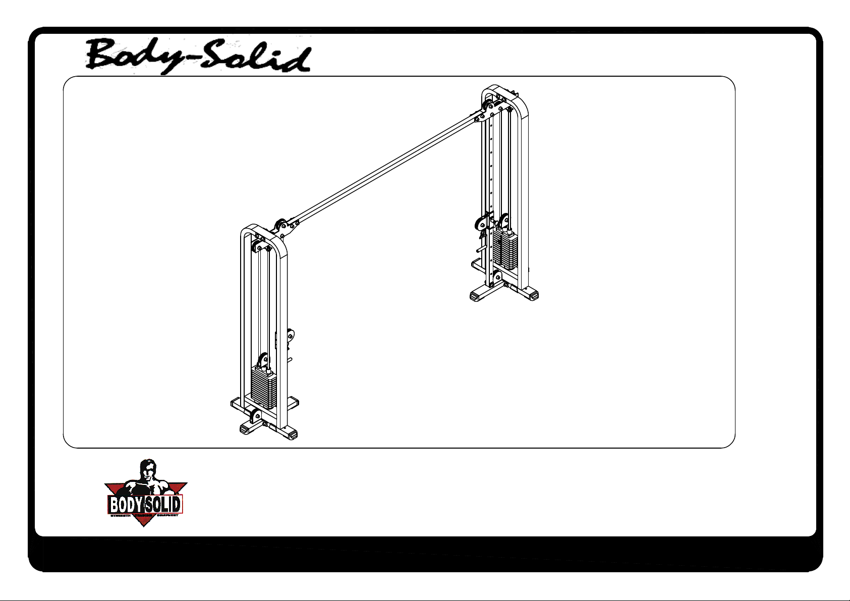
SCC-1200G
OWNER'S MANUAL
Page 2
SCC-1200G
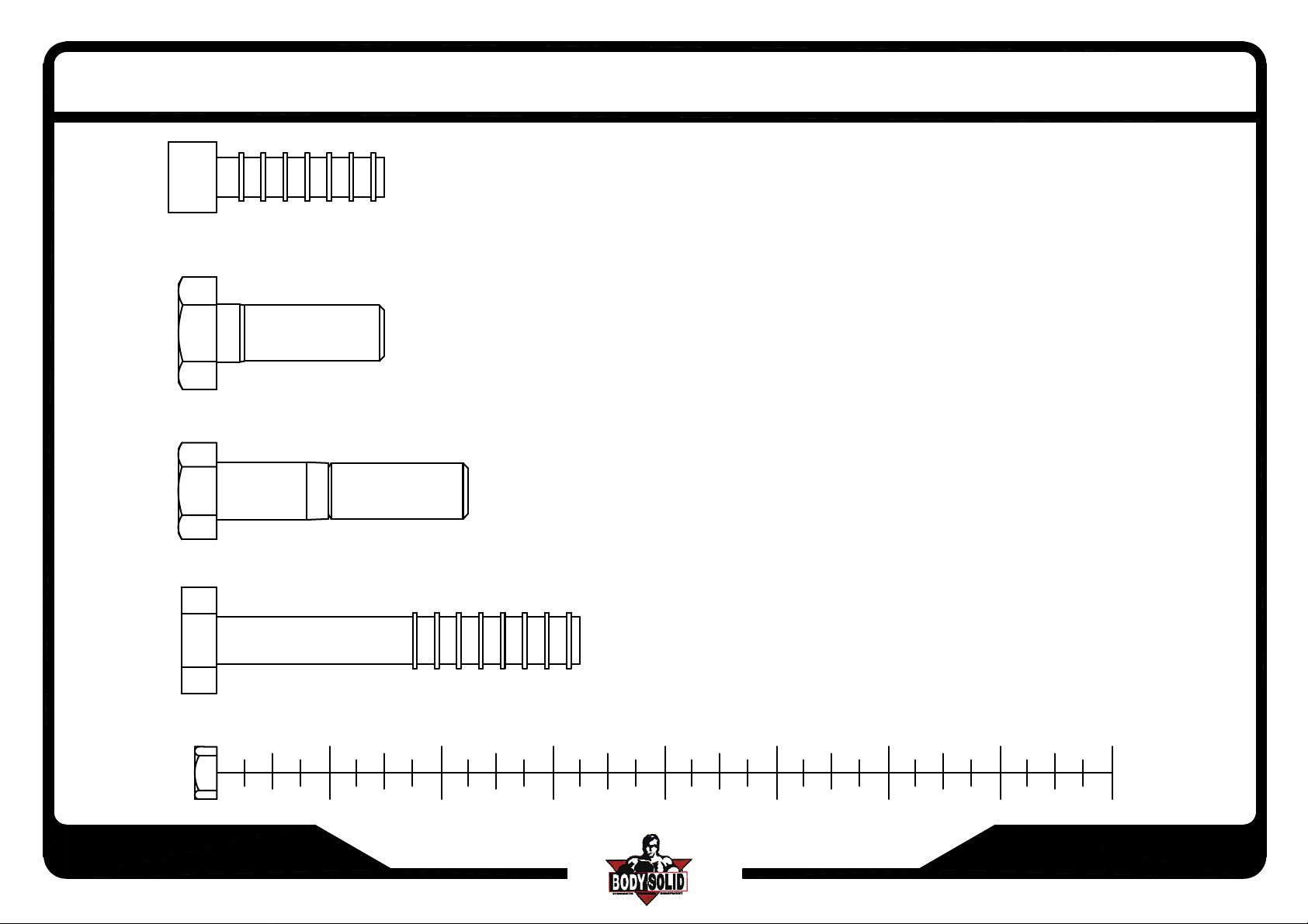
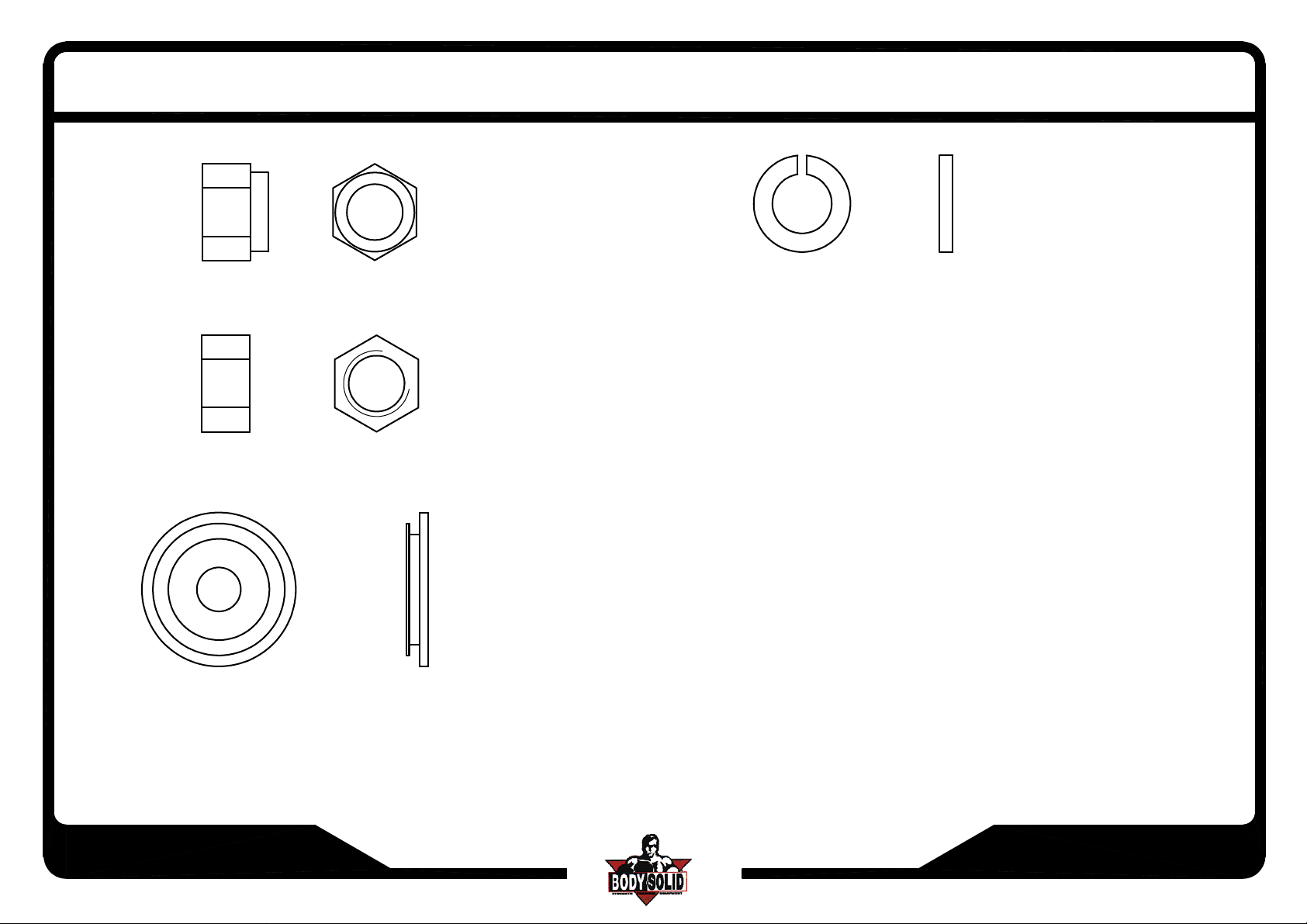
(A1)ROUND ALLEN HEAD 7/16"x1/2"L PARTIAL THREAD QTY.2
(A2)HEX BOLT 1/2"x1 1/2"L-13UNC PARTIAL THREAD QTY.2
ASSEMBLY INSTRUCTIONS
(A3)HEX BOLT 1/2"x2 1/4"L PARTIAL THREAD QTY.8
(A4)HEX BOLT 1/2"x3 1/4"L PARTIAL THREAD QTY.14
SCC1200G-082005
1
2
3
45
6
7
8
Page 1.1
Page 3
SCC-1200G
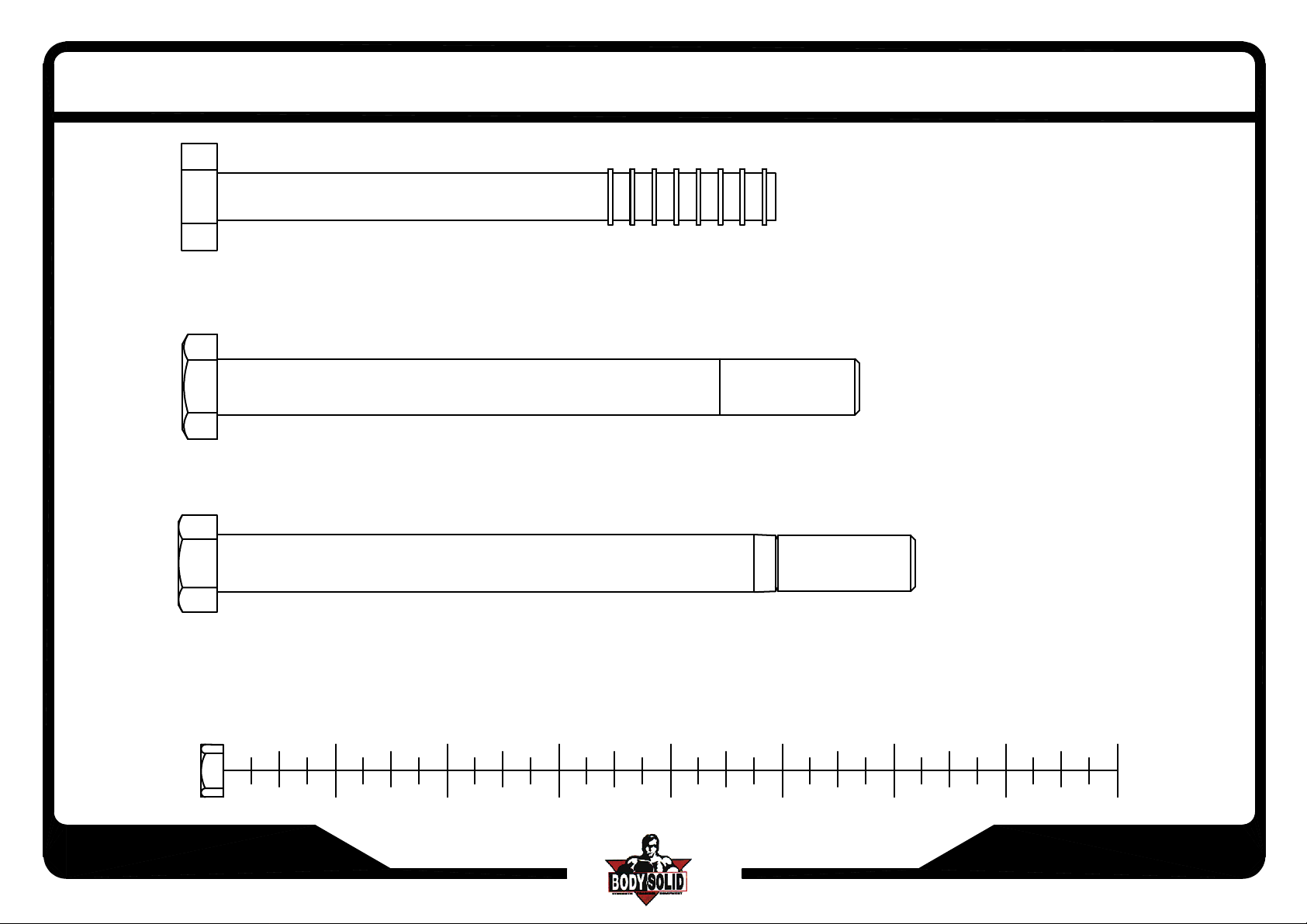
(A5)HEX BOLT 1/2"x5"L PARTIAL THREAD QTY.4
(A6)HEX BOLT 1/2"x5 3/4"L PARTIAL THREAD QTY.4
ASSEMBLY INSTRUCTIONS
(A7)HEX BOLT 1/2"x6 1/4"L PARTIAL THREAD QTY.2
SCC1200G-082005
1
2
3
45
6
7
8
Page 1.2
Page 4
SCC-1200G
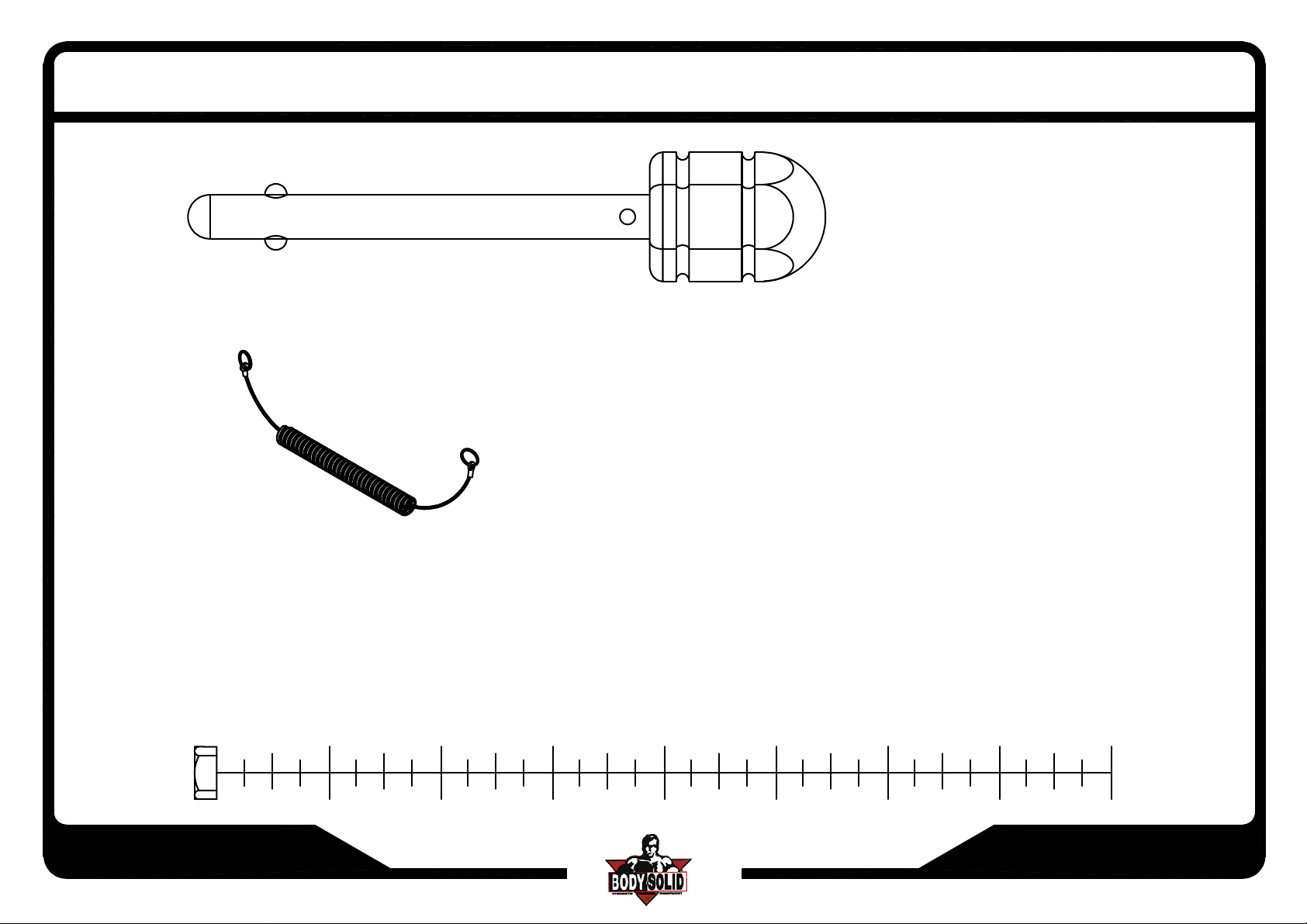
(A8)10LB PIN(8250-021) QTY.2
ASSEMBLY INSTRUCTIONS
(A9)ELASTIC BOLT QTY.2
SCC1200G-082005
1
2
3
45
6
7
8
Page 1.3
Page 5
SCC-1200G
ASSEMBLY INSTRUCTIONS
(B1)NYLON LOCK NUT 1/2" QTY.32
(B2)LOCK NUT 1/2"-13UNC QTY.2
(C1)1/2"(I.D.)ROUND END CAP WASHER QTY.60
(C2)1/2"(I.D.)SPRING WASHER QTY.2
SCC1200G-082005
Page 1.4
Page 6

SCC-1200G
ASSEMBLY INSTRUCTIONS
HARDWARE ILLUSTRATION
D1.1/2" BOLT CAP(9212-024)------------------------[60PCS]
D2.
n4 1/2" PULLEY(9213-010A)-----------------------[6PCS]
n4 1/2" PULLEY(9213-010B)-----------------------[8PCS]
D3.
D4.2"x4" FOOT CAP(9211-028)-------------------------[8PCS]
n4" RUBBER DOUNT(9310-017)-----------------[4PCS]
D5.
D6.STIRRUP HANDLE(8290-002)---------------------[2PCS]
D7.SPRING SNAP LINK(8810-001)--------------------[2PCS]
n3/4" SHAFT COLLAR(9211-050)----------------[4PCS]
D8.
D9.WEIGHT SELECTOR BAR(8220-061)-----------[2PCS]
D10.CHROME TOP PLATE(8400-002)---------------[2PCS]
D11.8300mm STEEL CABLE----------------------------[2PCS]
D12.60X50 NYLON BUSHING(9211-033)-----------[4PCS]
D13.
n5/8" ROUND END CAP(9211-015)-----------[4PCS]
D14.2"x4" RUBBER DOUNT(9212-009)-------------[4PCS]
D1 D2 D3
D4
D7
D10 D11
D5
D8
D6
D9
SCC1200G-082005
D12
D13
D14
Page 2
Page 7

SCC-1200G
ASSEMBLY INSTRUCTIONS
PARTS ILLUSTRATION SHEET
A[2PCS] WEIGHT STACK FRAME
B[2PCS]UPRIGHT PILLAR
C[1PCS] TOP CROSS SUPPORT
E[2PCS] BOTTOM PILLAR FRAME
F[2PCS] BOTTOM PULLEY FRAME
D[2PCS] TOP PULLEY FRAME
G[2PCS]
MIDDLE PULLEY HOLDER
SCC1200G-122010
Page 3
Page 8

SCC-1200G
ASSEMBLY INSTRUCTIONS
HARDWARE ILLUSTRATION
H[1PCS]
ADJUSTABLE CROSSOVER FRAME
I[4PCS]8280-004
CHROME GUIDE ROD
K[1PCS]
ADJUSTABLE CROSSOVER FRAME
J[2PCS]8323-014
TOP PLATE PULLEY FRAME
L[2PCS]9220-009
PROTECT PLABK
SCC1200G-122010
Page 4
Page 9

SCC-1200G
ASSEMBLY INSTRUCTIONS
Ax2
Above shows STEP 1
assembled and completed
SCC1200G-082005
D4x2
D4x2
Ex2
D1x4
D13x2
B1x4
D14x2
C1x4
Fx2
D14x2
D13x2
D4x2
D1x4
A6x4
C1x4
D4x2
Page 5
Page 10

SCC-1200G
Above shows STEP 2
assembled and completed
ASSEMBLY INSTRUCTIONS
D1x4
B1x4
C1x4
C1x4
A5x4
D1x4
Dx2
D8x2
Ix2
D8x2
*:Before the assembling of the weight stacks:
Finish (step 1) and adjust the distance between
the two bases to 3307mm(130in)
SCC1200G-082005
D10x2
D5x2
Ix2
D5x2
PAGE 1
)
n
i
30
1
(
m
m
7
30
3
t
u
bo
A
Page 6
Page 11

SCC-1200G
ASSEMBLY INSTRUCTIONS
D1x4
B1x4
D12
K
Above shows STEP 3
assembled and completed
D3
D1
B1
G
D1x2
B1x2
C1x2
C1x2
A4x2
D1
B1
D1x2
C1
C
D3
G
C1
A7
D12
H
A3
Bx2
D1
D12
B1
C1x4
C1x4
A4x4
D1x4
D1x2
B1x2
C1x2
C1x2
A4x2
D1x2
D12
D1
B1
SCC1200G-122010
C1
C1
A3
Page 7
Page 12

SCC-1200G
ASSEMBLY INSTRUCTIONS
D3
A2x2
Above shows STEP 4
assembled and completed
D1x2
B1x2
C1x2
A1x2
D1x2
B1x2
C1x2
D1x2
B1x2
C1x2
C1x2
A3x2
B2x2
C2x2
A
D1x2
Jx2
C1x2
A3x2
D1x2
D3x2
SCC1200G-082005
D3x2
C1x2
A3x2
D1x2
A8x2
DETIAL A
D9x2
Page 8
Page 13

SCC-1200G
ASSEMBLY INSTRUCTIONS
D2x6
C1x6
B1x6
D1x6
Above shows STEP 5
assembled and completed
C1x6
A4x6
D1x6
D7x2
D6x2
SCC1200G-082005
Page 9
Page 14

SCC-1200
ASSEMBLY INSTRUCTIONS
D11
Cable to constitute illustration
D11
*
D11
*
SCC1200G-122010
*:NEED TO LOOSEH BOTH ALLEN HEAD BOLT
IN ORDER TO REMOVE SHAFT
Page 9.1
Page 15

SCC-1200G
Step-1 is spelled as SETP-1
The Steps should read as fo l lows
NOTE: DO NOT TIGHTEN NUTS
AND BOLTS SECURELY UNTIL YOU HAVE COMPLETED ALL ASSEMBLY STEP
Step - 1
*Attach D14 Rubber Dount's to Bottom of A Weight Stack Frame.
*Insert D4 Foot Cap's into ends of E Bottom Pillar Frame,
F Bottom Pulley Frame and A Weight Stack Frame.
*Attach E Bottom Pillar Frame and F Bottom Pulley Frame to A Weight Stack Frame.
Step - 2
*Attach I Chrome Guide Rod's and D5 Rubber Donut's to A Weight Stack Frame.
*In this order slide Weight Stack, D10 Chrome Top Plate,
and D8 Shaft Collar's onto I Chr ome Guide Rod's.
*Insert D Top Pulley Frame onto I Chrome Guide Rod's and then attach to A Weight Stack Frame.
*Insert D8 Shaft Collar's into D Top Pulley Frame.
*Repeat all the steps above in order to assemble opposite side.
Step - 3 - Use this step on both sides
*Attach D3 Pulley to G Middle Pulley Holder.
*Attach G Middle Pulley Holder to K or H Adjustable Crossover Frame.
*Insert D12 Nylon Bushing's to both sides of K or H Adjustable Crossover Frame.
*Slide K or H Adjustable Crossover Frame onto B
Upright Pillar - Pull red mushroom cap adjuster to slide on.
*Attach B Upright Pillar to E Bottom Pillar Frame and D Top Pulley Frame
*Attach C Top Cross Support to D Top Pulley Frame
Step - 4 - Use this step on both sides
*Attach J Top Plate Pulley Frame and small ring of A9 Elastic Bolt to D9 Weight Selector Bar.
*Attach D3 Pulley to J Top Plate Pulley Frame.
*Attach D9 Weight Selector Bar to D10 Chrome Top Plate.
*Attach large ring of A9 Elastic Bolt to A8 10Lb. Pin.
*Attach D3 Pulley to E Bottom Pillar Frame.
*Attach D3 Pulley to F Bottom Pulley Frame.
ASSEMBLY INSTRUCTIONS
CABLE CROSSOVER
SAFETY RULES
1. Periodically check that all nuts, bolts and screws are fully tightene d on
your CABLE CROSSOVER MACHINE.
2. Exercise with care.Perform your exercises at a smooth moderate pace;
never perform jerky or uncoordinated movements that may cause injury.
3. It is recommended that you should workout with a training parther.
4. Warning:
EXERCISE PROGRAM.IT IS ADVISABLE TO HAVE A PHYSICAL
EXAMINATION BEFORE YOU ENTER ANY EXERCISE PROGRAM.
FOR YOUR OWN SAFETY,DO NOT BEGIN ANY EXERCISE
WITHOUT PROPER INSTRUCTION.
Step - 5 - Use this step on both si des.
*Attach D2 Pulley to insid e of D Top Pulley Frame.
*Attach D3 Pulley to ou tside of D Top Pulley Fram e.
*Attach D6 Stirrup Handle to H and K Adjustable Crossover Frame.
Step - 6
*Attach Cables as shown in cable routing instructions.
*Tighten all Bolts
*Attach all Bolt Caps and L Protect Plate.
CONSULT YOUR PHYSICIAN BEFORE STARTING YOUR
SCC1200G-122010
Page 10
Page 16

SCC-1200G
Above shows STEP 6
assembled and completed
ASSEMBLY INSTRUCTIONS
L
SCC1200G-082005
L
Page 11
 Loading...