

Page 1
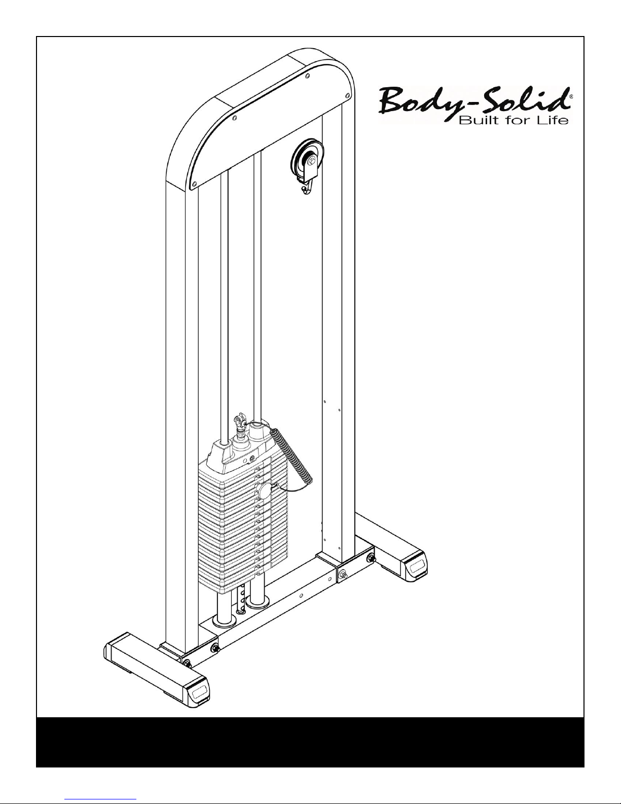
ASSEMBLY INSTRUCTIONS
G-STACK
Page 2
S T E P
1
Be careful to assemble all components in the
sequence they are presented.
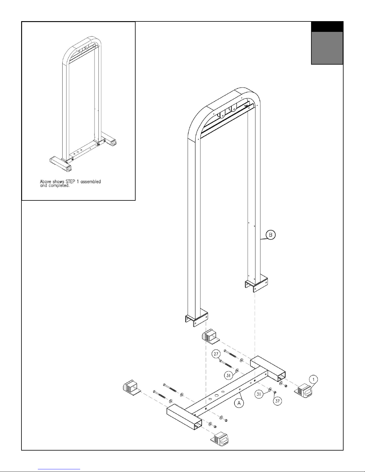
A. Attach Lower Main Frame (A) to the Upper Main Frame (B) as shown using:
Four 27 (3/8” x 4” hex head bolt)*
Eight 31 (3/8” washer)
Four 37 (3/8” nylon lock nut)
B. Slide four Foot Caps (1) into Lower Base Frame (A).
MM
Inch
Page 3
S T E P
1
Page 4
S T E P
2
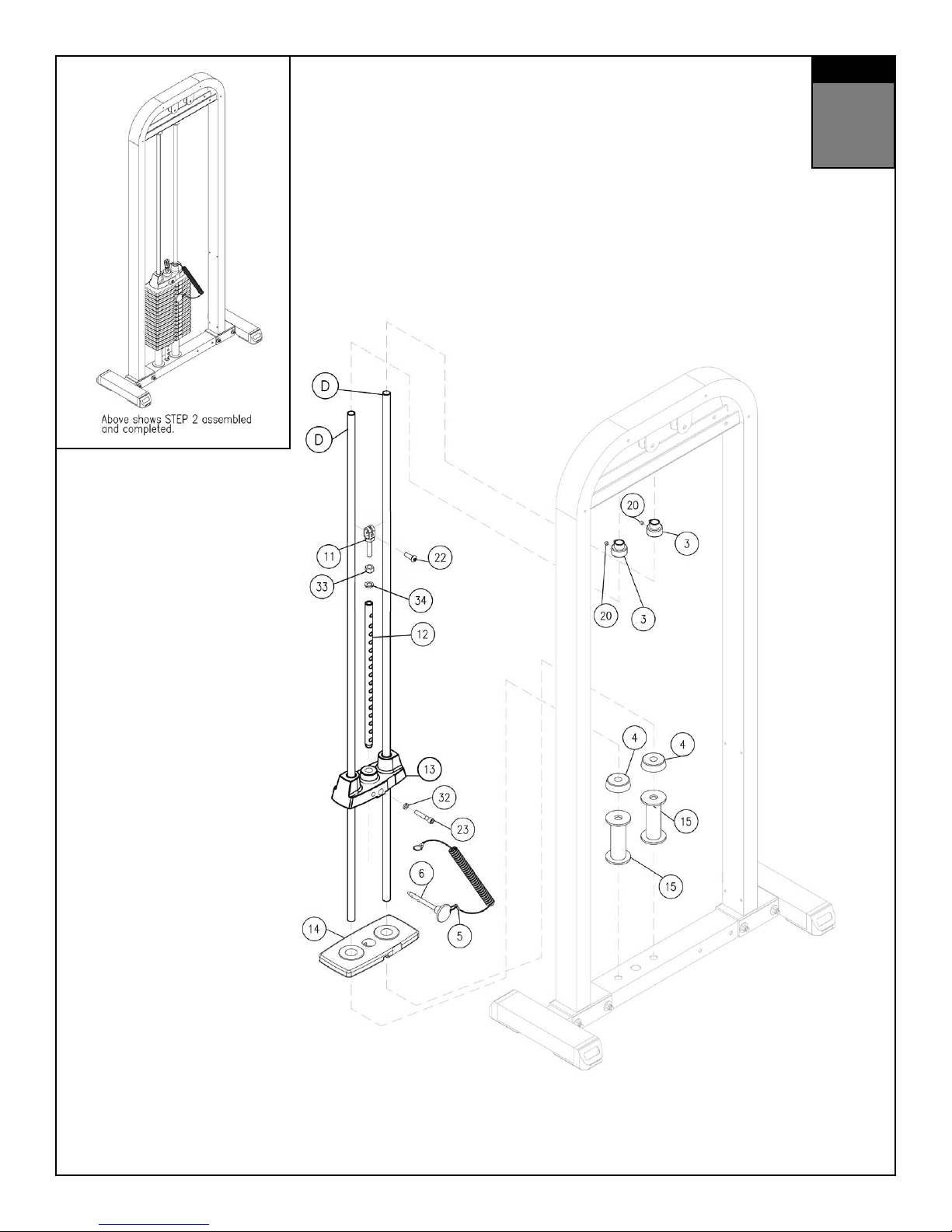
Be careful to assemble all components in the
sequence they are presented.
A. Install chrome guide rods (D) into the holes in the lower frame.
B. Install weight raiser (15) and rubber donut (4) and slide to bottom of the guide
rod.
C. Tilt guide rods away from main frame and install weight plates (14). Be
careful to hold guide rods steady when installing weight plates.
D. Install chrome selector rod (12) into the top plate (13) and secure with allen
head bolt (23) and washer (32) and fully tighten bolt. Install the spring lock
washer (34) and jam nut (33) onto the selector rod top bolt (11) and install
assembly into the top of the selector rod (12).
E. Install top plate and selector rod assembly onto the guide rods.
F. Install shaft collars (3) onto guide rods and align guide rods so they are
directly below the guide rod holes in the upper section of the frame.
G. Slide shaft collars upward, aligning the key extension on the shaft collars
with the slot extensions in the upper frame holes.
H. Turn shaft collars so they lock the guide rods into position and fully tighten
allen screws (20).
I. Install weight stack pin (6) and lanyard (5) assembly on the cable by installing
cable through the key ring end.
MM
Inch
Page 5
S T E P
2
Page 6
S T E P
3
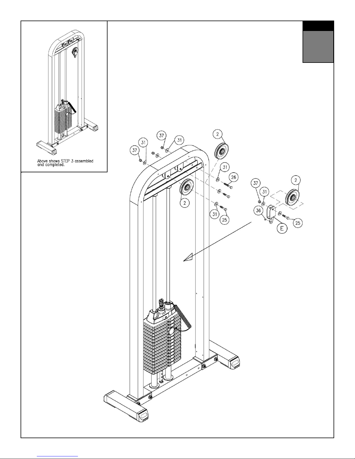
Be careful to assemble all components in the
sequence they are presented.
A. Install pulleys (2) into frame with bolt (25), washer (31), and
nylon lock nut (37). Fully tighten bolts.
B. Install cable end bolt (26) into frame with washers (31) and
nylon lock nuts (37). Secure the lock bolt but do not fully tighten until after
installing the cable.
C. Assemble the floating pulley assembly by installing pulley (2) into pulley
bracket (5) with bolt (25), washers (31) and nylon lock nut (37). Install
chrome cap nut onto threaded end of pulley racket hook.
MM
Inch
Page 7
S T E P
3
Page 8
S T E P
4
Be careful to assemble all components in the
sequence they are presented.
A. Install cable by first assembling the ball end of the cable into the selector rod
top bolt (11) and attaching the cable cylinder lock over the ball end. Secure
with provided allen screw.
B. Install cable over pulleys (A1 and A2) and through floating pulley
assembly (A3).
C. Attach cable end with open eye onto the bolt assembly (25). Fully tighten
bolts.
MM
Inch
Page 9
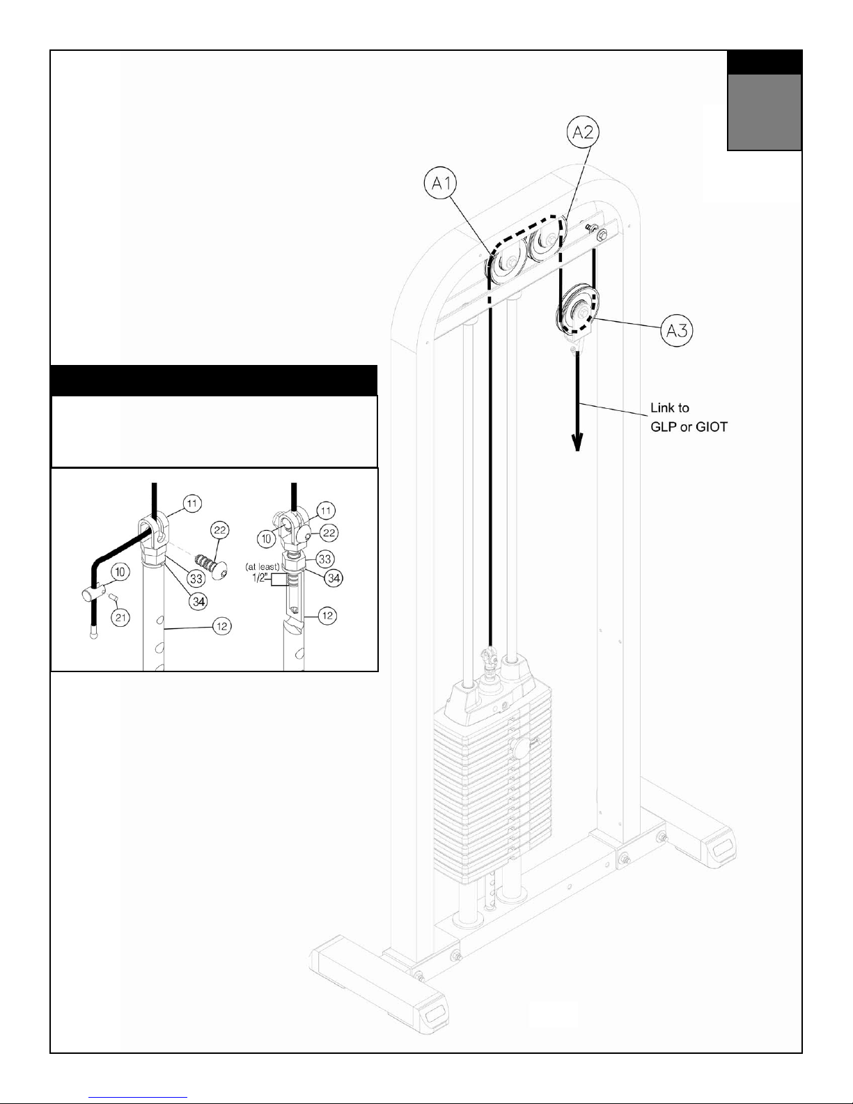
WARNING
Selector Rod Top Bolt (11) must be threaded a minumum of 1/2”
into the Selector Rod (12), and Jam Nut (33) tightened securely
against spring lock washer (34) to ensure proper connection.
Check the Jam Nut (33) once a week to make sure it is tight.
S T E P
4
Page 10
S T E P
Be careful to assemble all components in the
5
sequence they are presented.
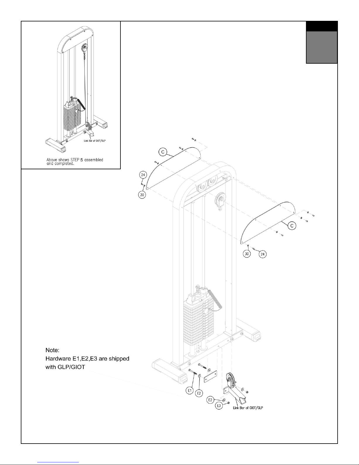
A. Install pulley shrouds (C) onto frame with screws (24) and washers (30). Fully
tighten screws.
B. Attach completed assembly to Body Solid Inner / Outer Thigh or Leg Press
machine.
C. Bolts (E1), washers (E2), nylon nuts (E3), backing plate and extension link bar
will be supplied with either of the exercise stations. The station can be
installed on either side of the GSTCK assembly. Follow installation directions
provided with the exercise station to attach to GSTCK.
MM
Inch
Page 11
S T E P
5
Page 12

G STACK Main Frame Parts List
KEY# QTY PART# DESCRIPTION
A
B
C
D
E
1
1
2
2
1
STCKMF-A
STCKUMF-B
STCKSD-C
STCKGR-D
STCKFPB-E
LOWER MAIN FRAME
UPPER MAIN FRAME
SHROUD
GUIDE ROD
FLOATING PULLEY BRACKET
Key #, Part #, and Discription are required when ordering parts.
Page 13

G STACK Hardware List
KEY# QTY PART# DESCRIPTION
1
2
3
4
5
6
10
11
12
13
14
15
20
21
22
23
24
25
26
27
30
31
32
33
34
37
4
3
2
2
1
1
1
1
1
1
15/20
2
2
1
1
1
8
3
1
4
8
16
1
1
1
8
CFC23
CPP4.25
CSC
CRD
CLAN
CWSP
CCES
CSRTB
CSR
CTP10
CWSP10
CWR
CAS.31X.37FT
CAS.15X.37FT
CHEX.37X.87PTB
CSHAB.37X2
CAS.25X.5
CHEX.37X2PTB
CHEX.37X2.5PTB
CHEX.37X4PTB
CWFLT.25
CWFLT.37
CSLW.37
CJN.5
CSLW.5
CNLN.37
FOOT CAP 2” X 3”
PULLEY 4 1/4” OD
SHAFT COLLAR
RUBBER DONUT
LANYARD
WEIGHT STACK PIN
CABLE END SHAFT
SELECTOR ROD TOP BOLT
SELECTOR ROD
TOP PLATE 10lbs
WEIGHT STACK PLATE10lbs
WEIGHT RISER
ALLEN SCREW 5/16” X 3/8” FULL THREAD
ALLEN SCREW 5/32” X 3/8” FULL THREAD
HEX HEAD BOLT 3/8” X 7/8” PARTIAL THREAD
SOCKET HEAD ALLEN BOLT 3/8” X 2”
ALLEN SCREW 1/4” X 1/2” FULL THREAD
HEX HEAD BOLT 3/8” X 2” PARTIAL THREAD
HEX HEAD BOLT 3/8” X 2 1/2” PARTIAL THREAD
HEX HEAD BOLT 3/8” X 4” PRT THREAD
WASHER 1/4”
WASHER 3/8”
SPRING LOCK WASHER 3/8”
JAM NUT 1/2”
SPRING LOCK WASHER 1/2”
NYLON LOCK NUT 3/8”
Key #, Part #, and Discription are required when ordering parts.
Page 14

1900 S. Des Plaines Ave.
®
Forest Park, Il 60130
1 (800) 556-3113
Hours: M-F 8:30 - 5:00
www.bodysolid.com
Copyright 2009. Body-Solid. All rights reserved. Body-Solid reserves the right to change design and specications when we feel it will improve the product.
c
Body-Solid machines maintain several patented and patent pending features and designs. All rights reserved on all design patents and utility patents.
 Loading...