

Body-Solid BFCT1 User Manual
owner’s manual
v. BFCT1-030812

TABLE OF CONTENTS
I. BEFORE YOU BEGIN...........................................
II. IMPORTANT SAFETY INSTRUCTIONS...............
III. FEATURES.............................................................
IV. DIMENSIONS.........................................................
V. ASSEMBLY INSTRUCTIONS................................
VI. SETTING UP YOUR BFCT1.................................
VII. CONSOLE FEATURES..........................................
VIII. CONSOLE DISPLAY FEATURES..........................
IX. CONSOLE OPERATION........................................
X. EXERCISE TIPS AND GUIDELINES.....................
3
4
5
6
7 – 21
22 – 23
24
25
26 – 31
32 – 33
XI. TROUBLESHOOTING...........................................
XII. SERVICING THE BFCT1......................................
XIII. HARDWARE...........................................................
XIV. HARDWARE LIST.................................................
XV. EXPLODED VIEW DIAGRAM...............................
www.BestFitness.com
34
35
36 – 38
39 – 42
44 – 45
2

BEFORE YOU BEGIN
Thank you for purchasing the Best Fitness Cross Trainer BFCT1.
To maximize your use of the equipment please study this Owner’s Manual thoroughly.
Unpacking the Equipment
The BFCT1 is carefully tested and inspected before shipment. We have shipped the unit in
several pieces that require assembly. Ask for assistance during the assembly process.
Best Fitness Equipment continually seeks ways to improve the performance, specifications and product manuals in order to ensure
that only superior products are released from our factories. Please take the time to carefully read through this manual thoroughly.
Instructions contained in this document are not intended to cover all details or variations possible with Best Fitness Equipment, or to
cover every contingency that may be met in conjunction with installation, operation, maintenance or troubleshooting of the equipment.
Even though we have prepared this manual with extreme care, neither the publisher nor the author can accept responsibility for any
errors in, or omission from, the information given. Should additional information be required, or should situations arise that are not
covered by this manual, the matter should be directed to your local Best Fitness Equipment representative, or the Service Department
at Best Fitness Equipment in Forest Park, Illinois.
Any Questions?
Call (800) 556-3113
3

IMPORTANT SAFETY INSTRUCTIONS
Before beginning any fitness program, you should obtain a complete physical
examination from your physician.
Il est conseille de subir un examen medical complet avant d’entreprendre tout programme d’exercise. Si vous avez des
etourdissements ou des faiblesses, arretez les exercices immediatement.
Antes de comenzar cualquier programma de ejercicios, deberias tener un examen fisico con su doctor.
WHEN USING EXERCISE EQUIPMENT, YOU SHOULD ALWAYS TAKE BASIC
PRECAUTIONS, INCLUDING THE FOLLOWING:
Read all instructions before using the BFCT1. These instructions are written to ensure your
•
safety and to protect the unit.
Do not allow children on or near the equipment.
•
Use the equipment only for its intended purpose as described in this guide. Do not use ac-
•
cessory attachments that are not recommended by the manufacturer. Such attachments
might cause injuries.
Wear proper exercise clothing and shoes for your workout, no loose clothing.
•
Use care when getting on or off the unit.
•
Do not overexert yourself or work to exhaustion.
•
If you feel any pain or abnormal symptoms, stop your workout immediately and consult your
•
physician.
Never operate the unit when it has been dropped or damaged. Return the equipment to a
•
service center for examination and repair.
Never drop or insert objects into any opening in the equipment.
•
Always check the unit before each use. Make sure that all fasteners are secure and in good
•
working condition.
Do not use the equipment outdoors or near water.
•
PERSONAL SAFETY DURING ASSEMBLY
It is strongly recommended that a qualified dealer assemble the equipment. Assistance is
•
required.
Before beginning assembly, please take the time to read the instructions thoroughly.
•
Read each step in the assembly instructions and follow the steps in sequence. Do not skip
•
ahead. If you skip ahead, you may learn later that you have to disassemble components and
that you may have damaged the equipment.
Assemble and operate the BFCT1 on a solid, level surface. Locate the unit a few feet from
•
the walls or furniture to provide easy access.
The BFCT1 is designed for your enjoyment. By following these precautions and using common
sense, you will have many safe and pleasurable hours of healthful exercise with your Best Fitness BFCT1.
After assembly, you should check all functions to ensure correct operation. If you experience
problems, first recheck the assembly instructions to locate any possible errors made during assembly. If you are unable to correct the problem, call the dealer from whom you purchased the
machine or call 1-800-556-3113 for the dealer nearest you.
4
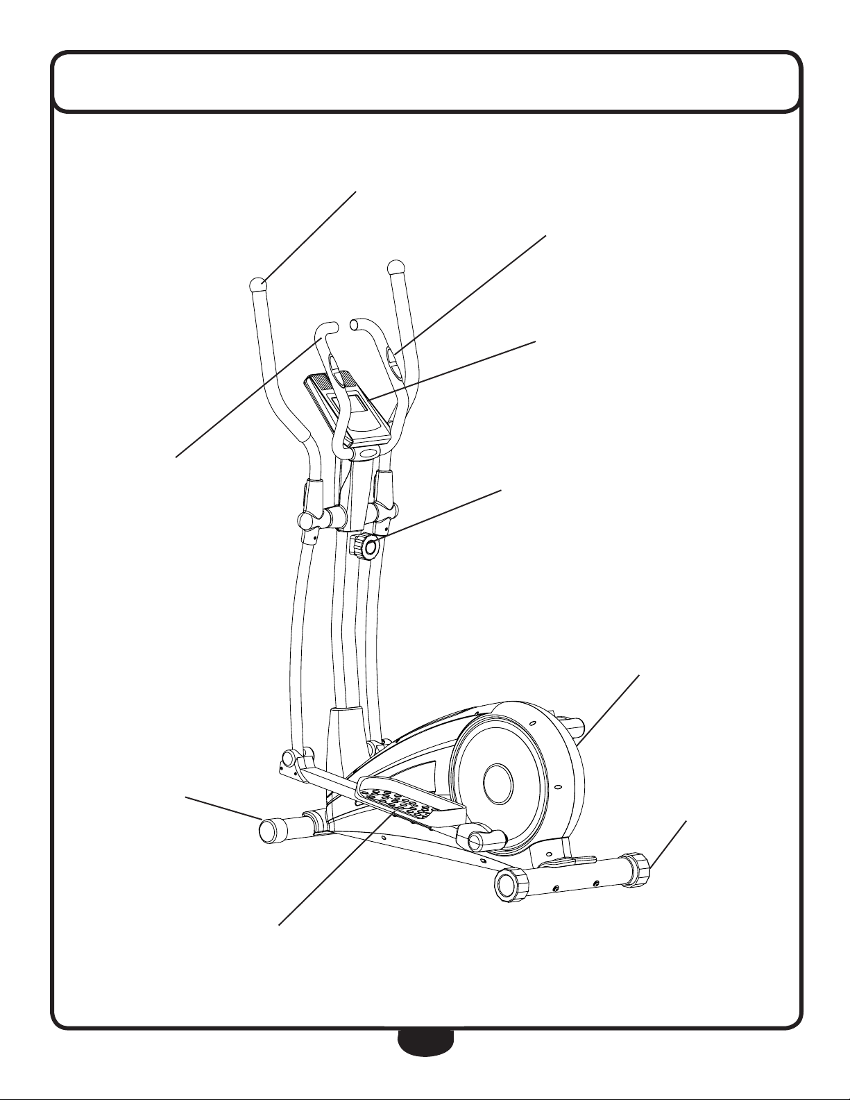
FEATURES
ERGONOMIC HANDLE BARS
CONTACT HEART RATE SENSORS
CONSOLE
STATIONARY HANDLE
TRANSPORT WHEELS
TENSION ADJUSTMENT
FULLY SHROUDED FLYWHEEL
LEVEL STABILIZER
FOOT PLATE
5
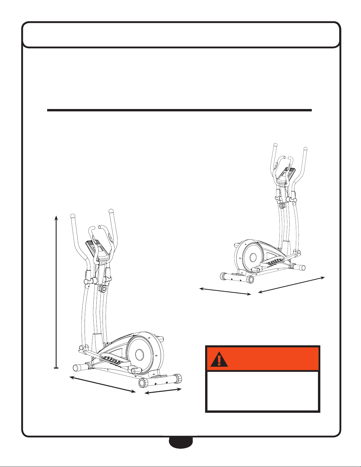
DIMENSIONS
."9-0"%
-#,(
7!2.).'
The room layout diagram below will help you decide the best placement for your BFCT1.
The dimensions of the BFCT1 are: Width 1’ 9” X Length 4’ 3”.
The usage space is: Width 3’ X Length 6’ (The usage space is the overall space needed for
operation).
The usage space needed for the BFCT1 could be more, depending on the user.
Suggested Usage Space
Minimum Usage Space
5’ 5”
4’ 3”
6’
3’
1’ 9”
250LB (113KG)
6
ASSEMBLY INSTRUCTIONS
Assembly of the BFCT1 takes professional installers about 1/2 hour to complete. If this is
the first time you have assembled this type of equipment, plan on significantly more time.
Professional installers are highly recommended!
However, if you acquire the appropriate tools, obtain assistance, and follow the assembly
steps sequentially, the process will take time, but is fairly easy.
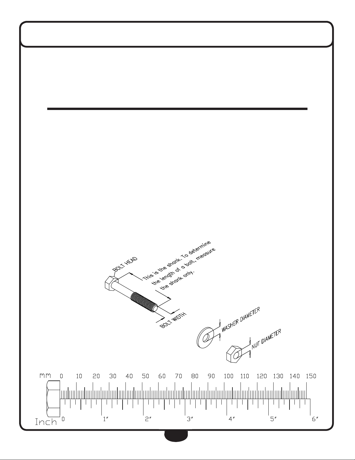
ASSEMBLY TIPS
Read all “Notes” on each page before beginning each step.
While you may be able to assemble the BFCT1
using the illustrations only, important safety
notes and other tips are included in the text.
Some pieces may have extra holes that you
will not use. Use only those holes indicated in
the instructions and illustrations.
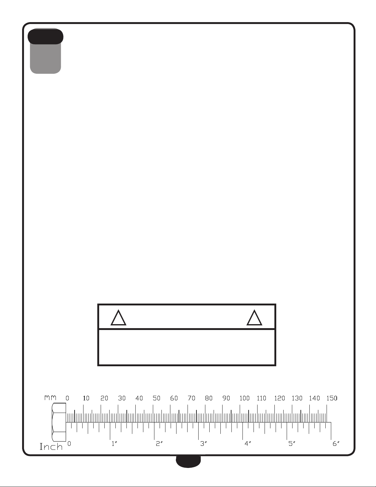
NOTE: To find out the length of a particular
bolt, measure its shank (the long, narrow part
beneath the head).
Refer to the following diagram:
NOTE: After assembly, you should check all
functions to ensure correct operation. If you
experience problems, first recheck the assembly instructions to locate any possible errors
made during assembly.
If you are unable to correct the problem, call
the dealer from whom you purchased the machine or call 1-800-556-3113 for the dealer
nearest you.
*** Some of the hardwares
has been preinstalled.
7

S T E P
Be careful to assemble all components
1
in the sequence they are presented.
1A. Connect Rear Leg (B) to Main Frame (A) using:
Two 4 (M8X90mm Round Allen Head Bolt)
Two 58 (M8X25mm Arc Washer)
NOTE: Use the larger 8mm washer.
1B. Connect Front Leg (C) to Main Frame (A) using:
Two 21 (M8X72mm Round Allen Head Bolt)
Two 20 (M8X19mm Arc Washer)
NOTE: Use the smaller 8mm washer.
8
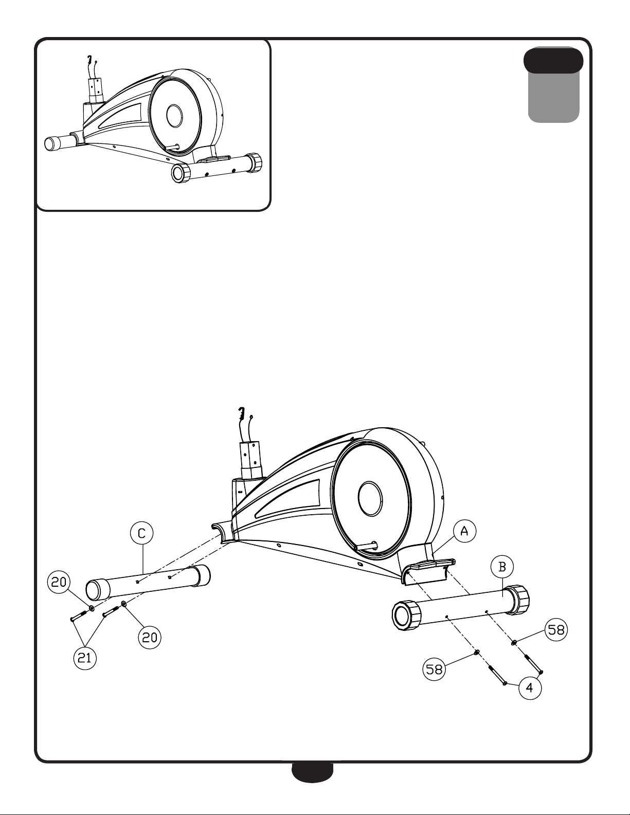
Above shows STEP 1 assembled and completed.
S T E P
** Some of the hardwares
have been preinstalled.
1
9
S T E P
Be careful to assemble all components
2
in the sequence they are presented.
2A. Slide Shroud (E) onto Upright (D).
2B. Attach Upper Tension Cable (48) to Lower Tension Cable (52) as
shown in Diagram 1. Push Upper Tension Cable (48) towards Lower
Tension Cable (52) as shown in Diagram 2. Pull the cable up as shown in
Diagram 3 then seat it in the slot. Pull out Plastic Component (99) as
shown in Diagram 4.
2C. Connect Upper Harness (50) to Lower Harness (53).
2D. Slide Upright (D) onto Main Frame (A) and secure using:
Four 45 (M8X16mm Round Allen Head Bolt)
Four 44 (M8 Spring Washer)
Four 12 (M8 Washer)
2E. Let Shroud (E) slide to the bottom of Upright (D).
! !
WARNING
DO NOT FORCE TENSION
CABLE DURING INSTALLATION.
10
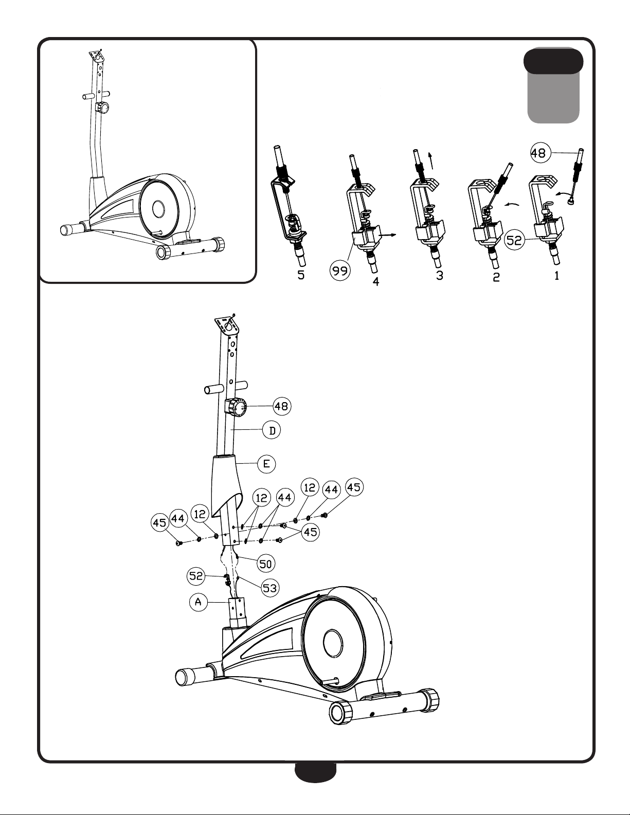
Above shows STEP 2 assembled and completed.
** Some of the hardwares
** Some of the hardwares
have been preinstalled.
have been preinstalled.
S T E P
2
11

S T E P
Be careful to assemble all components
3
in the sequence they are presented.
3A. Insert both Shafts (61) into Upright (D).
3B. Secure Left Stride Bar (F) and Right Stride Bar (G) onto Upright (D) using:
Two 10 (M10X20mm Round Allen Head Bolt)
Two 11 (M10 Spring Washer)
Two 9 (M16.2 D-Washer)
Two 35 (M17 Wave Washer)
3C. Secure Left Foot Frame (14) onto Left Crank (55) and Right Foot Frame
(15) onto Right Crank (56) using:
Two 10 (M10X20mm Round Allen Head Bolt)
Two 11 (M10 Spring Washer)
Two 9 (M16.2 D-Washer)
Two 35 (M17 Wave Washer)
3D. Secure Left Stride Bar (F) to Left Foot Frame (14) using:
One 18 (Ø12x68xM10x12 Hex Head Bolt)
One 62 (M12 Washer)
One 5 (M10 Washer)
One 6 (M10 Nylon Lock Nut)
3E. Secure Right Stride Bar (G) to Right Foot Frame (15) using:
One 18 (Ø12x68xM10x12 Hex Head Bolt)
One 62 (M12 Washer)
One 5 (M10 Washer)
One 6 (M10 Nylon Lock Nut)
3F. Insert Left Handle (H) onto Left Stride Bar (F) and secure using:
Two 36 (M8X45mm Carriage Bolt)
Two 20 (M8 Arc Washer)
Two 13 (M8 Nylon Lock Nut)
3G. Insert Right Handle (I) onto Right Stride Bar (G) and secure using:
Two 36 (M8X45mm Carriage Bolt)
Two 20 (M8 Arc Washer)
Two 13 (M8 Nylon Lock Nut)
12
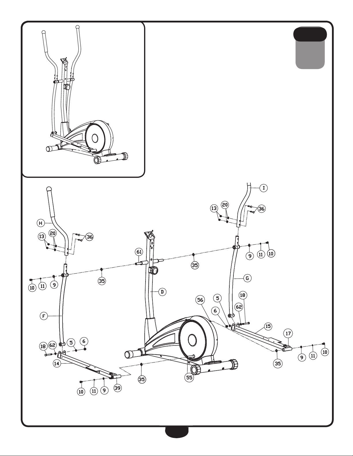
Above shows STEP 3 assembled and completed.
S T E P
** Some of the hardwares
have been preinstalled.
3
13

S T E P
Be careful to assemble all components
4
in the sequence they are presented.
4A. Connect Left Foot Plate (J) to Left Foot Frame (14) using:
Three 37 (M8X45mm Hex Head Bolt)
Three 12 (M8 Washer)
Three 13 (M8 Nylon Lock Nut)
4B. Connect Right Foot Plate (K) to Right Foot Frame (15) using:
Three 37 (M8X45mm Hex Head Bolt)
Three 12 (M8 Washer)
Three 13 (M8 Nylon Lock Nut)
14
 Loading...