

Page 1
B4R
Endurance® B4R Recumbent Bike
User Manual
V. B4R-041315
Page 2

Table of Contents
Table of Contents......................................................................................................
Introduction................................................................................................................
Important Safety Information..............................................................................
Before You Begin.......................................................................................................
Assembly......................................................................................................................
Setting up B4R...........................................................................................................
Dimension........................................................................................................................................
Console Overview.....................................................................................................
Console Operation....................................................................................................
Monitoring Your Heart Rate.................................................................................
Chest Strap Operation.............................................................................................
General Maintenace.................................................................................................
Troubleshooting Guide..........................................................................................
2
3
4
5
6 - 15
16
17
18 - 19
20 - 26
27 - 28
29
30
31
Stretching & Flexibility...........................................................................................
Warm-Up/Cool Down Exercises..........................................................................
Parts & Hardware List..............................................................................................
Exploded Drawing...................................................................................................
Endurance® continually seeks ways to improve the performance, specications and product manuals in order to ensure that only superior
products are released from our factories. Please take the time to carefully read through this manual thoroughly. Instructions contained in
this document are not intended to cover all details or variations possible with Endurance
may be met in conjunction with installation, operation, maintenance or troubleshooting of the equipment. Even though we have prepared
this manual with extreme care, neither the publisher nor the author can accept responsibility for any errors in, or omission from, the informa
tion given. Should additional information be required, or should situations arise that are not covered by this manual, the matter should be
directed to your local Endurance® representative, or the Service Department at Endurance® in Forest Park, Illinois.
Copyright 2012. Endurance®. All rights reserved. Endurance® reserves the right to change design and specications when we feel it will
c
improve the product. Endurance® machines maintain several patented and patent pending features and designs. All rights reserved on
all design patents and utility patents.
equipment, or to cover every contingency that
®
32
33 - 39
40 - 43
44 - 45
-
2
Page 3

Introduction
Congratulations!!
Thank you for purchasing your new Endurance® Recumbent Bike.
Using state-of-the-art techniques, robust frame structure and superior ergonomic
design, Endurance® Recumbent Bike set a new standard for excellence. The
Endurance® Recumbent Bike can improve your quality of life by keeping you t
and healthy, increasing your energy levels and enhancing your lifestyle.
Endurance® wants to ensure years of quality workouts with your new Recumbent
bike so we recommend that you read this manual carefully and thoroughly to fully understand proper use and maintenance of this product. Retain this Owner’s
Manual for future reference.
Please use this Owner’s Manual to make sure that all parts have been included
in your shipment. When ordering parts, you must use the part number and description from this Owner’s Manual. Use only Endurance® replacement parts when
servicing this machine. Failure to do so will void your warranty and could result in
personal injury.
For information about product operation or service, check out the ocial Endurance® website at www.bodysolid.com/Home/Endurance_Cardio or contact an authorized Endurance® dealer or an Endurance® factory-authorized service company or contact Endurance® Customer Tech Support at one of the following:
Toll Free: 1-800-556-3113
Phone: 1-708-427-3555
Fax: 1-708-427-3556
Hours: M-F 8:30-5:00 CST
E-Mail: service@bodysolid.com
Or write to:
Endurance® Service Department
1900 S. Des Plaines Ave.
Forest Park, IL 60130 USA
3
Page 4

Important Safety Information
Save this Owner’s Manual!
Before beginning any tness program, you should obtain a complete physical
examination from your physician.
When using exercise equipment, you must always take basic precautions, including the
following:
m Read all instructions before using your Endurance® Recumbent Bike.
These instructions are written to ensure your safety and to protect the unit.
m DO NOT allow children on or near the equipment.
m Use the equipment only for its intended purpose as described in this guide.
m DO NOT use accessory attachments that are not recommended by the
manufacturer. Such attachments might cause injuries and will void your warranty.
m Wear proper exercise clothing and shoes for your workout, no loose clothing.
m DO NOT use cleats, spikes or any other non-athletic shoes.
m DO NOT use this product while barefoot or wearing only socks.
m Use care when getting on or o the unit.
m DO NOT overexert yourself or work to exhaustion. If you experience any pain such
as chest pains, nausea, dizziness, shortness of breath or abnormal symptoms, stop
your workout immediately and consult your physician before continuing.
m Never operate the unit when it has been dropped or damaged.
Return the equipment to a service center for examination and repair.
m Never drop or insert objects into any opening in the equipment.
m Always check the unit for loose components before each use.
m DO NOT turn pedals by hand.
m DO NOT use the equipment outdoors or near water. It is imperative that your
Endurance® Recumbent bike is used in a climate controlled environment. If your
recumbent bike has been exposed to colder temperatures or to high moisture
climates, it is strongly recommended that the recumbent bike is brought to room
temperature before use. Failure to use this equipment in a climate controlled
environment may cause premature electronic failure.
m Endurance® recommends that a mat is placed under the unit to protect the oor or
carpet and for easier cleaning.
Endurance® Recumbent bikes are designed for your enjoyment. By following these precautions and using common sense, you can have many safe and pleasurable hours of healthful
exercise with your Endurance® Recumbent bike.
4
Page 5

Before You Begin
The Endurance® B4R is carefully tested and inspected before shipment. We have
shipped the unit in several pieces that require assembly. Carefully unpack the unit in
a clear area and lay the pieces on the oor near the area where you plan to use the
equipment. Remove the packing material. Do not dispose of the packing material
until assembly is complete and the unit is working properly. Place the unit on a clean
level surface for assembly. Before assembling, the unit should be placed as close as
possible to its nal location. Be careful to assemble all components in the sequence
presented in this guide.
PERSONAL SAFETY DURING ASSEMBLY
m It is strongly recommended that a qualied dealer assemble the equipment.
Assistance is required.
m Before beginning assembly, please take the time to read the instructions
thoroughly.
m Read each step in the assembly instructions and follow the steps in sequence.
Do not skip ahead. If you skip ahead, you may learn later that you have to
disassemble components and that you may have damaged the equipment
which will void the warranty.
m Assemble and operate the Endurance® Recumbent bike on a solid, level
surface.
Locate the unit a few feet from the walls or furniture to provide easy access.
AFTER ASSEMBLY
Once the unit is assembled, you should check all functions to ensure correct operation. If you experience problems, rst recheck the assembly instructions to locate
any possible errors made during assembly. If you are unable to correct the problem,
call the dealer from whom you purchased the machine or call Endurance® Customer
Tech Support Hot Line Toll Free at: 1-800-556-3113.
5
Page 6

Step 1
NOTE:
Some hardware components may be pre-assembled. Be aware of
Nylon lock nuts not fully screw onto bolts, they must be tightened
with a wrench to ensure proper engagement.
1A. Attach Front Stabilizer (G) to Main Frame (A) using:
Two M10x20mm Button Head Cap Screws (#1)
Two M10 Lock Washers (#2)
Two M10 Washers (#3)
1B. Attach Rear Stabilizer (B) to Main Frame (A) using:
Two M10x20mm Button Head Cap Screws (#1)
Two M10 Lock Washers (#2)
Two M10 Washers (#3)
1C. Attach Leveler (#5) to Main Frame (A)
1D. Attach Left Pedal (E) to Left Crank (#10)
1E. Attach Righ Pedal (F) to Right Crank(#11)
6
Page 7
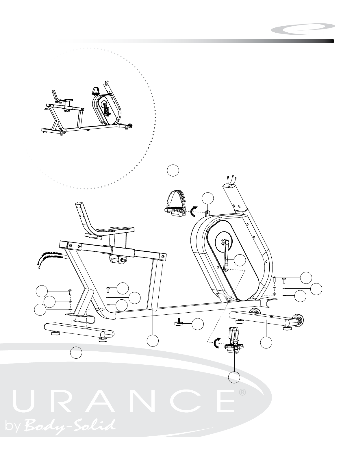
Above shows STEP 1 assembled and completed.
Step 1
E
10
11
1
1
2
3
B
1
2
3
5
A
G
2
3
7
F
Page 8

Step 2
NOTE:
Some hardware components may be pre-assembled. Be aware of
Nylon lock nuts not fully screw onto bolts, they must be tightened
with a wrench to ensure proper engagement.
2A. Attach the Handle Bar (M) to the Seat Frame (M) using:
Two M8x50mm Carriage Bolts (#35)
Two M8 Washers (#18)
Two M8 Acorn Nuts (#36)
2B. Connect Heart Rate Cables (#33) to the Heart Rate Cables (#13) on
the Main Frame.
2C. Attach the Lever Handle (#45) to the Shaft (#42) using:
Two M6x10mm Socket Head Cap Screws
8
Page 9
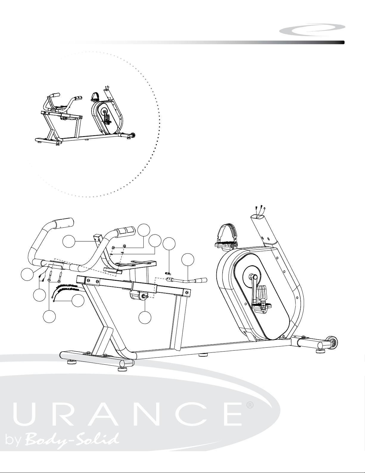
Above shows STEP 2 assembled and completed.
。
。
Step 2
D
33
35
M
13
36
42
18
40
45
9
Page 10

Step 3
NOTE:
Some hardware components may be pre-assembled. Be aware of
Nylon lock nuts not fully screw onto bolts, they must be tightened
with a wrench to ensure proper engagement.
3A. Attach Seat Pad (#21) to the Seat Frame (M) using:
Four M8x16mm Button Head Cap Screw (#17)
Four M8 Washer (#18)
3B. Attach Back Rest (#24) to the Seat Frame (M) using:
Four M6x40mm Button Head Cap Screw (#27)
Four M6 Washer (#28)
3C. Attach Plastic Cover (#26) to the Seat Frame (M) using:
One ST4.2x18mm Pan Head Phillips Screw (#12)
10
Page 11

Step 3
步骤三:
1.用内六角盘头螺钉(17)、平垫(18)将座垫(21)锁紧在椅座(M)上;
2.先用内六角盘头螺钉(27)、平垫(28)将网状靠背(24)锁紧在椅座(M)上;
然后用十字盘头自攻螺钉(12)将靠背小护罩(26)锁紧在椅座(M)上。
Above shows STEP 3 assembled and completed.
26 27
12
24
21
28
18
17
M
11
Page 12

Step 4
NOTE:
Some hardware components may be pre-assembled. Be aware of
Nylon lock nuts not fully screw onto bolts, they must be tightened
with a wrench to ensure proper engagement.
4A. Insert the Holder Top Half (H) to UPRIGHT FRAME (C)
4B. Insert the Holder Bottom Half (Q) to MAIN FRAME (A)
4C. Connect Upper Heart Rate Cables (#22) to Lower Heart Rate
Cables (#13).
4D. Connect Upper Wire Harness (#23) to Lower Wire Harness (#14).
4E. Attach Upright Frame (C) to Main Frame (A) using:
Two M10x50mm Socket Head Cap Screw (#15)
Two M10 Washer (#3)
Two M10 Nylon Lock Nut (#7)
4F. Attach the Holder Top Half (H) to the Holder Bottom Half (Q) using:
Three ST4.2x18mm Pan Head Phillips Screws (#12)
4G. Attach the Water Bottle Holder (#16) to Upright Frame (C) using:
Two ST4.2x18mm Pan Head Phillips Screws (#12)
12
Page 13
Above shows STEP 4 assembled and completed.
CC
15
16
12
H
12
Step 4
16
12
CC
H
12
15
3
7
13
23
22
14
Q
12
A
13
Page 14

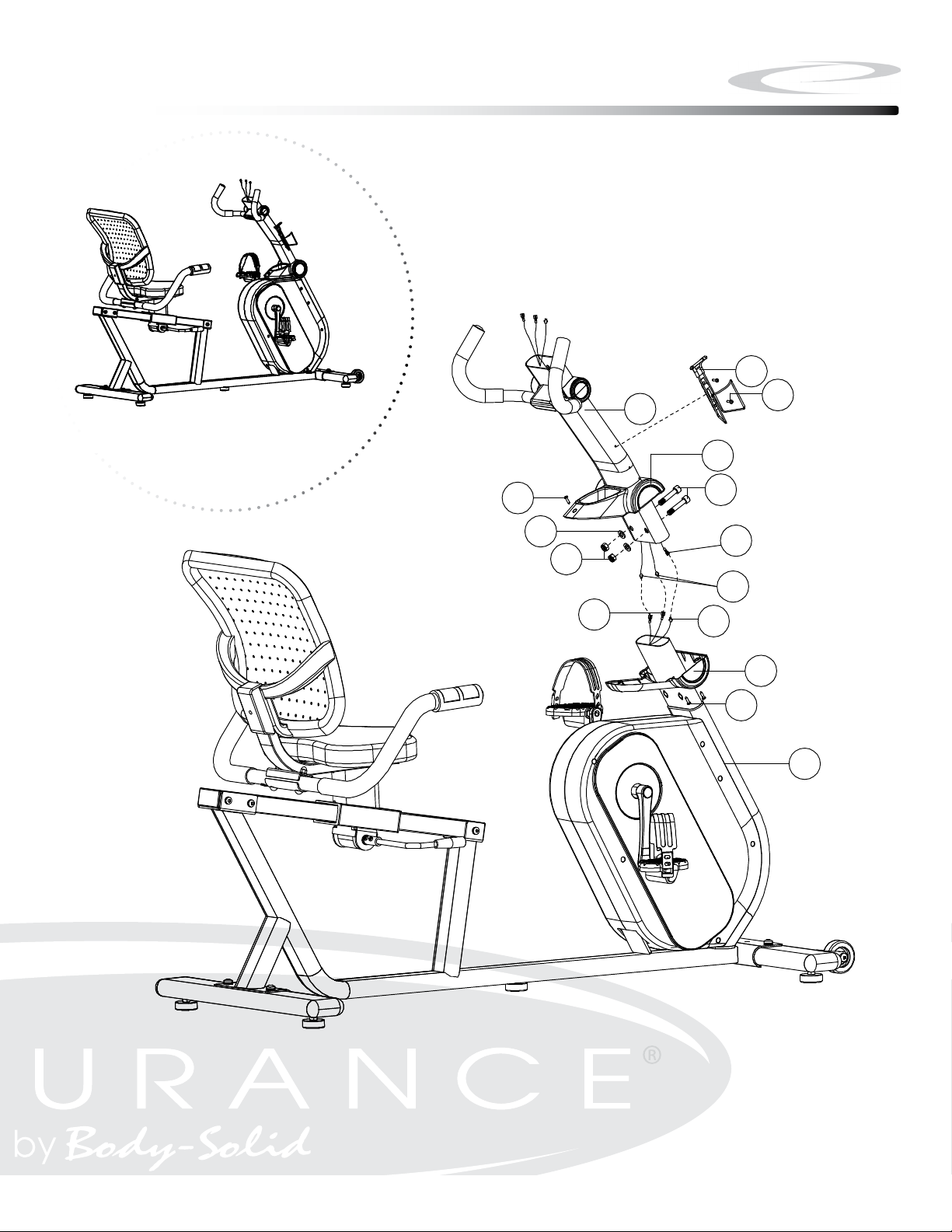
Step 5
NOTE:
Some hardware components may be pre-assembled. Be aware of
Nylon lock nuts not fully screw onto bolts, they must be tightened
with a wrench to ensure proper engagement.
5A. Attach L Shape Holder (N) to Console (L) using
Two M5x10mm Pan Head Phillips Screw (#20)
5B. Attach Console Mounting Plate (19) to Upright Frame (C) using:
Two M8x16mm Button Head Cap Screw (#17)
Two M8 Flat Washer (#18)
5B. Connect Heart Rate Cables (22) to the Heart Rate Cables of the
Console (L).
5C. Connect Wire Harness (23) to the Wire Harness of the Console (L).
5D. Attach Console (L) to Console Mounting Plate (19) using:
Four M5x10mm Pan Head Phillips Screw (#20)
14
Page 15

Above shows STEP 5 assembled and completed.
L
20
20
N
22
23
17
18
19
20
步骤五:
穿出,然后用内六角盘头螺钉(17)、平垫(18)将表托板(19)锁紧在 把立管
(C)上;
2.用十字盘头螺钉(20)将书报板(N)锁紧在电子表(L)上;
3.先将握把中继线二(22)、感应中继线(23)与电子表(L)相应的线连接好。
再用十字盘头螺钉(20)将电子表(L)锁紧在把立管(C)上.
N
20
Step 5
L
22
23
17
20
20
19
20
18
CC
15
Page 16

SETTING UP B4R
PLACEMENT IN YOUR HOME
To make exercise a desirable daily activity for you, the B4R should be placed in a comfort-
able and attractive setting. This bike is designed to use minimal oor space and to t nicely
in your gym/home.
Do not place or operate the B4R outdoors.
Do not place the B4R near water or in high moisture content environment.
It is highly recommended to place a dedicated equipment mat beneath your B4R.
A dedicated mat provides superior stability and rmness for a proper workout.
MOVING THE B4R
This bike is easy to move around safely.
To move the B4R:
1. Grasp the back end Frame
2. Simply roll the B4R on its two wheels
to the desired location.
There are ve Levelers can be
used to level the B4R:
1. Rotate the Adjustable Pads clockwise
or counter-clockwise to adjust the level
of the bike.
LEVELING THE B4R
16
Page 17

1635 mm
64.4 in.
Dimensions
26.4 in.
670 mm
17
48.7 in.
1237 mm
Page 18

Console Overview
Take a few moments to review the console Screen layout.
18
Page 19

Console Overview
CONSOLE DISPLAY
Resistance Level
The resistance level display is located on the upper left side of the screen . There are
24 resistance Levels to choose from.
User Prole
The User prole display is located on the upper right side of the screen. There are 5
user proles can be entered into the program.
Heart Rate
When the user’s heart rate signal is detected via heart rate sensor on the handlebar
or wireless chest strap, the user’s current heart rate will be displayed in the middle
right side of the screen.
Time
Time display is located on the lower left side of the screen. It shows the total elapsed
time or remaining time based on the current program.
RPM/Speed
RPM/Speed display is located in the lower middle side of the screen. It will alternate
the display between RPM/Speed. The unit for Speed is either Miles-per-Hour or
Kilometers-per-Hour based on current console setting.
Distance
Distance is located on the left side of RPM/Speed Display. The unit is either Miles
or Kilometers based on current console setting.
Watt/Calories
Watt/Calories display is located on the lower right side of the screen, It will alternate
the display between Watt and Calories.
19
Page 20

Console Overview
CONSOLE BUTTONS
Quick Program Buttons
The Quick Program buttons all the user to launch a program quickly. The programs
are MANUAL, PROGRAM, FITNESS, WATT, PERSONAL, HRC and RANDOM.
Up & Down Buttons
The Up and Down arrow buttons are for adjusting values in both program and setup
modes.
Quick Start Button
Press the Quick Start Button to immediately launch the Quick Start program and
bypass data entry.
Start/Stop Button
Press the Start/Stop Button during the Setup Mode will start the program.
Press the Start/Stop Button during the Program Run Mode will Pause the program.
Enter Button
The Enter button will conrm the selection in the setup mode.
Reset Button
The Reset button will erase current data and return to the setup mode.
20
Page 21

Console Operation
MODES
Setup Mode: When Powered on, the console beeps and then goes into setup mode.
Sleep Mode: When RPM Signal or Data is not detected for 4 minutes, it will
automatically enter Sleep Mode. Pedal again or press any button to start the
program again.
USER SETUP MODE
When entering the program, You have the option of entering your own personal
settings (Gender, Age, Height, Weight).
1. In the Setup Mode, hold the Reset Button until it display “U0” on the screen.
(Figure #1 & #2)
2. Press Up or Down Buttons to choose from U0 ~ U4 and then press Enter
Button.
3. Press Up or Down Buttons to choose the Gender and then press Enter Button.
4. Press Up or Down Buttons to adjust the Age and then press Enter Button.
5. Press Up or Down Buttons to adjust the Height and then press Enter Button.
6. Press Up or Down Buttons to adjust the Weight and then press Enter Button.
Figure #1 Figure #2
QUICK START PROGRAM
This is the quickest way to start a workout. After the console is powered up, Press the
Quick Start Button to begin the workout program. In Quick Start Mode, Time will count
up from zero and all workout data will start to accrue. Resistance Level can be adjusted
by pressing Up or Down Buttons. There are 24 levels of resistance available.
21
Page 22

Console Operation
PRESET PROGRAMS
There are seven Pre-Set Programs (MANUAL, PROGRAM, FITNESS, WATT,
PERSONAL, H.R.C., RANDOM) to choose from.
MANUAL
This program allows the user to have the complete control over their workout
(Figure #3). The user can make adjustment on resistance level from 1 to 24.
To start the program,
1. In the Setup Mode, Press Up or Down Buttons to choose MANUAL program
and then press Enter Button.
2. Press Up or Down Buttons to adjust the Level and then press Enter Button.
3. Press Up or Down Buttons to adjust the Time and then press Enter Button.
4. Press Up or Down Buttons to adjust the Distance and then press Enter Button.
5. Press Up or Down Buttons to adjust the Calories and then press Start Button.
PROGRAM
This program has a total of 12 dierent exercise proles (Figure #4).
To start the program,
1. In the Setup Mode, Press Up or Down Buttons to choose PROGRAM program
and then press Enter Button.
2. Press Up or Down Buttons to choose P1-P12 and then press Enter Button.
3. Press Up or Down Buttons to adjust the Level and then press Enter Button.
4. Press Up or Down Buttons to adjust the Time and then press Enter Button.
5. Press Up or Down Buttons to adjust the Distance and then press Enter Button.
6. Press Up or Down Buttons to adjust the Calories and then press Start Button.
Strength: It is designed to increase muscular strength in your lower body. This progarm will steadily increase in resistance to a high level and then maintain at that level to
help build the users’ strength and endurance (Figure #10).
Cardio: It is designed to increase your Cardio vascular function. It builds up your heart
muscle and increases blood ow and lung capacity (Figure #11).
22
Page 23

Console Operation
上海祺电电子科技有限公司(VISTA CO. LTD.)
Page 5 8/13/2012
Figure State
F1 EXCELLENT
F2 VERY GOOD
F3 GOOD
F4 FAIR
F5 POOR
F6 VERY POOR
Hill: It is designed to take the user through two hill proles. Resistance changes are
small during this program. This is a good program to get started with or for someone
looking for a lower stress workout (Figure #12 - #13).
Fat Burn: It is designed to get user’s heart rate fast and maintains it at 65% of your
calculated maximum heart rate with slight variation to provide optimal calories burn .
(Figure #14 - #15)
Interval: It is designed to vary the intensity of the workout between low and high
resistance to quickly raise and lower the heart rate thru a series of high & low proles
(Figure #16 - #18).
Speed Training: This program simulates interval training with more extreme levels of
high and low intensity levels (Figure #19 - #21).
FITNESS
This program helps determine the physical tness of the user (Figure #5). The Testing
time is eight minutes. After the test, the result will display on the screen as below.
Figure State
F1 VERY GOOD
F2 GOOD
F3 FAIR
F4 POOR
F5 VERY POOR
23
Page 24

Console Operation
WAT T
This program allows the user to adjust Watt value to acheive dierent resistance
level (Figure #6). To Start the program,
1. In the Setup Mode, Press Up or Down Buttons to choose WATT program
and then press Enter Button.
2. Press Up or Down Buttons to adjust the Time and then press Enter Button.
3. Press Up or Down Buttons to adjust the Distance and then press Enter Button.
4. Press Up or Down Buttons to adjust the Calories and then press Start Button.
PERSONAL
This program allows the users to build their own workout prole (Figure #7).
To start the program,
1. In the Setup Mode, Press Up or Down Buttons to choose PERSONAL
2. Press Up or Down Buttons to adjust Resistance Level and then press Enter
Button.
3. Press Up or Down Buttons to adjust the Time and then press Enter Button.
4. Press Up or Down Buttons to adjust the Distance and then press Enter Button.
5. Press Up or Down Buttons to adjust the Calories and then press Start Button.
H.R.C.
Heart rate control programs are designed to automatically change resistance to keep
your heart rate at a predetermined level based on the selected Heart Rate program.
Each Heart Rate program is designed with a specic goal in mind (Figure #8).
To Start the program,
1. In the Setup Mode, Press Up or Down Buttons to choose H.R.C.
2. Press Up or Down Buttons to choose 55%, 75%, 90% or Tag and then press
Enter Button. If the user choose Tag, the user needs to set his/her our target
heart rate by pressing Up or Down Buttons to adjust the value.
3. Press Up or Down Buttons to adjust the Time and then press Enter Button.
4. Press Up or Down Buttons to adjust the Distance and then press Enter Button.
5. Press Up or Down Buttons to adjust the Calories and then press Start Button.
24
Page 25

Console Operation
RANDOM
This program generates a random exercise prole for the user (Figure #9).
To Start the program
1. In the Setup Mode, Press Up or Down Buttons to choose RANDOM
2. Press Up or Down Buttons to adjust Time and then press Enter Button.
3. Press Up or Down Buttons to adjust the Distance and then press Enter Button.
4. Press Up or Down Buttons to adjust the Calories and then press Start Button.
PRESET PROGRAMS
Figure #3 Figure #4 Figure #5
Figure #6 Figure #7
Figure #9
Figure #8
25
Page 26

Console Operation
12 EXERCISE PROFILE PROGRAMS
Figure #10
Figure #13 Figure #15Figure #14
Figure #16
Figure #11
Figure #17
Figure #12
Figure #18
Figure #19
Figure #20
26
Figure #21
Page 27

Monitoring Your Heart Rate
To obtain the greatest cardiovascular benets from your exercise workout, it is important to work within your target heart rate zone. The American Heart Association
(AHA) denes this target as 60% -75% percent of the Maximum Heart Rate.
The Maximum Heart Rate may be roughly calculated by subtracting the user’s age
from 220.
The Maximum Heart Rate and aerobic capacity naturally decreases as the user ages.
This may vary from one person to another, but use this number to nd your approximate eective target zone. For example, the Maximum Heart Rate for an average 40
year-old is 180 bpm. The target heart rate zone is 60%-75% of 180 or 108-135 bpm.
See the FITNESS SAFETY section on page 28.
Before beginning a workout, check the normal resting heart rate. The user can place
their ngers lightly against the neck or wrist over the main artery. After nding the
pulse, count the number of beats in 10 seconds. Multiply the number of beats by six
to determine your pulse rate per minute. It is recommend to take a heart rate measurement at rest, after warming up, during the workout and two minutes into cooling
down after the workout, to accurately track progress as it relates to better tness.
During your rst several months of exercising, the AHA recommends aiming for the
lower part of the target heart rate zone - 60%, then gradually progressing up to 75%.
According to the AHA, exercising above 75% of the Maximum Heart Rate may be too
strenuous unless the user is in top physical condition. Exercising below 60% of the
maximum will result in minimal cardiovascular conditioning.
CHECK YOUR PULSE RECOVERY RATE
If your pulse is over 100 bpm ve minutes after stopping exercising, or if it’s higher
than normal the morning after exercising, the user’s exertion may have been too
strenuous for their current tness level. Rest and reduce the intensity next time.
27
Page 28

Monitoring Your Heart Rate
FITNESS SAFETY
The Heart Rate chart indicates average rate zones for dierent ages. A variety of different factors (including medication, emotional state, temperature and other conditions) can aect the target heart rate zone that is best for you. Your physician or
health care professional can help you determine the exercise intensity that is appropriate for your age and condition.
(MHR) = Maximum Heart Rate
(THR) = Target Heart Rate
220 - Age = Maximum Heart Rate (MHZ)
MHZ x .60 = 60% of your Maximum Heart Rate.
MHZ x .75 = 75% of your Maximum Heart Rate.
For example, if you are 30 years old, your calculations will be as follows:
220 - 30 = 190
190 x .60 = 114 (Low End or 60% of MHZ)
190 x .75 = 142 (High End or 75% of MHZ)
30 Year-Old (THR) Target Heart Rate would be 114-142
Maximum Heart Rate (MHR) Calculation
Heart Rate Training Zone Chart
28
Page 29

Chest Strap Operation
Your Endurance® Recumbent bike has the capability to determine Heart Rate with
the use of a Heart Rate Chest Strap. A Heart Rate Chest Strap can be purchased
seperately. In all Heart Rate Control programs, the console only accepts the heart
rate signal from the chest strap transmitter while the pulse grip heart rate function is
disabled. The requirement to wear the chest strap is due to the superior accuracy of
a chest strap transmitter compared to the pulse grip sensors.
It is suggested for the Chest Strap Transmitter that you position the transmitter as
close to your heart as possible, against the skin, 1-2 inches below the pectoral mus-
cles. For best results, moisten the back of the transmitter for better contact.
If no Heart Rate signal is detected for 10 seconds, the screen will show “0” Heart
Rate
HR Chest Strap for Endurance® models
SAFETY PRECAUTIONS AND TIPS FOR CHEST STRAP
1. It is the owner’s responsibility to ensure that all users of this unit have read the
Owner’s Manual and are familiar with warnings and safety precautions.
2. Do not place chest strap near devices that generate large magnetic elds. TV sets,
electric motors, radios, and high voltage power lines can aect the transmitter’s
performance. These items can interfere with the heart rate signal and possibly affect the heart rate readings on the console.
3. Handle the Chest Strap with care. Dropping the transmitter might cause damage
that could void the warranty.
4. Do not use the chest strap if you have a cardiac pacemaker or if your are taking
medications for a heart condition. Medication or electrical pulses from the pacemaker can interfere with accurate heart rate readings.
5. Do not bend the strips inside the chest strap. This can cause the chest strap to
loose conductivity.
6. The chest strap has batteries that need to be replaced periodically. A faulty battery can cause inaccurate reading.
29
Page 30

General Maintenace
Your Endurance® B4R Exercise Bike has been manufactured to withstand many hours
of use with minimal maintenance. Here are some maintenance tips to keep your Endurance® B4R Exercise Bike running at its best.
CLEANING
Periodically wipe down your machine with mild, soapy water or a diluted general
purpose non-abrasive household cleaner. Cleaner should never be applied directly
to any part of the equipment. Instead, place the non-abrasive cleaning solution on
a soft cloth and wipe down the unit. The Exercise Bike should be wiped down to remove sweat after each use.
SQUEAKING NOISE
If squeaking noise occurs, it is most likely one of these three reasons:
1. The hardware is not suciently tightened durring assembly. Please check and
tighthen all bolts.
2. Dirt buid-up on the rails and wheels. Clean the rails and wheels with a lint free
cloth and rubbing alcohol. After Cleaning, apply a small amount of lubricant on
Rail with your ngers or a lint free cloth.
3. The unit is not properly Leveled. There are two leveling pads on the rear legs to
adjust the level of the bike.
30
Page 31

Trouble Shooting Guide
Symptom
Console has no power.
Strides/Min
or Speed shows 0
No HR signal
or incorrect HR signal
Possible Cause
Console cable is not connected? Verify that the console cable is connected properly.
The console is faulty?
Computer isn’t receiving a
signal from the sensor?
The sensor is faulty?
The computer is faulty?
Computer is receiving a faint or
intermittent pulse signal.
Check to see if the chest strap is being properly worn by
the user - if skin is extremely dry, then moisten contact
Call the Endurance® service number.
Check that the sensor magnet is correctly
tted and passes in front of the sensor.
Check that all the computer plugs and sockets
are correctly and rmly connected.
If all above checks are O.K., then replace sensor.
Call the Endurance® service number.
Check to make sure that the batteries in
the chest strap are installed correctly.
Replace the chest strap batteries.
Check to see if the receiver is properly installed.
points on chest with water and try again.
Solution
Noise from Bike
If the problem still exists then call the
Endurance® service number.
Loose hardware or dirt build up.
Dirt build up.
The Problem still exists.
Check and tighten hardware
Call the Endurance® service number.
Any Questions?
Call the Customer Tech Hotline at:
1 (800) 556-3113
Clean up the dirt
31
Page 32

Stretching & Flexibility
Flexibility is an important component of physical tness and needs to be addressed in
a resistance training program. The two main purposes for stretching are injury prevention and a faster rate of recovery from exercise. Stretching should be performed in both
the warm up and cool down phases of a training session. A good general guideline is
that each workout session should be preceded by 5 to 15 minutes of general warm up,
followed by 8 to 12 minutes of stretching, and concluded with 4 to 5 minutes of postexercise stretching.
The following
A regular stretching program will loosen muscle tissue, allowing an increased range of
motion. This helps prevent micro-tears at the muscle-tendon junction. Almost 90% of
all injuries from muscle strain occur at the muscle-tendon junction. Repeated injury at
this junction can lead to a build-up of scar tissue, which impedes range of motion and
adds stress to the joints.
Begin by stretching the major muscle groups rst. Move in and out of your stretches with
smooth, slow, controlled motion. Hold the stretch for at least 10 seconds when you feel
you have reached your muscle’s maximum distance. Do not use fast, hurried or reckless
motions when stretching. Fast and bouncy motions will increase the risk of injury.
The most common and most popular type of stretching is the static stretching technique.
This form of stretching involves voluntary, complete relaxation of the muscles while they
are elongated. A static stretch is a constant, steady stretch in which the end position is
held for 10 to 30 seconds. This technique is popular because it is easy to learn, eective,
and accompanied by minimal soreness with the least risk of injury.
Ballistic stretching involves a bouncing or bobbing movement during the stretch. The
nal position in the movement is not held. Ballistic stretching is unpopular because of
the increased amount of delayed muscle soreness and the possibility of injury during the
stretching exercise. Ballistic stretching is not recommended.
A dynamic stretch involves exibility during sport specic movements. Dynamic stretching is similar to ballistic stretching in that it utilizes movement, but dynamic stretching includes movements that may be specic to a sport or movement pattern. Dynamic
stretching is most common among track and eld athletes, but is also used in other
sports, such as basketball and volleyball. An example of dynamic stretching would be a
track sprinter performing high knees with an emphasis on knee height and arm action,
not on horizontal speed.
pages show
illustrations with
descriptions of
static stretching
for warm up and
post-exercise
cool down.
Remember...
stretch your
large muscle
groups rst and
do all stretches
in a smooth,
slow, controlled
manner.
32
Page 33

Warm Up/Cool Down Exercises
UPPER BACK
Cross Arm in Front of Chest
MUSCLE(S) AFFECTED: latissimus dorsi and teres major
1. Stand or sit with the right arm slightly exed (15° to 30°) and adducted across the chest.
2. Grasp the upper arm just above the elbow, placing the left hand on the posterior side of the
upper arm.
3. Pull the right arm across the chest (toward the left) with the left hand; hold for 10 seconds.
4. Repeat with the left arm.
UPPER BACK
Arms Straight Up Above Head (Pillar)
MUSCLE(S) AFFECTED: latissimus dorsi and wrist exors
Stretching the upper back
1. Stand with arms in front of torso, ngers interlocked with palms facing each other.
2. Slowly straighten the arms above the head with palms up.
3. Continue to reach upward with hands and arms.
4. While continuing to reach upward, slowly reach slightly backward; hold for 10 seconds.
Stretching the shoulders, chest
and upper back
LOWER BACK
Spinal Twist (Pretzel)
MUSCLE(S) AFFECTED: internal oblique, external oblique and spinal erectors
1. Sitting with legs straight and upper body nearly vertical, place right foot on left side of left
knee.
2. Place back of left elbow on right side of right knee, which is now bent.
3. Place right palm on oor 12 to 16 inches behind hips.
4. Push right knee to the left with left elbow while turning shoulders and head to the right as
far as possible. Try to look behind the back. Hold for 10 seconds.
5. Repeat with left leg.
33
Stretching the lower back and
sides
Page 34

Warm Up/Cool Down Exercises
LOWER BACK
Semi-Leg Straddle
MUSCLE(S) AFFECTED: spinal erectors
1. Sitting, knees exed 30 to 50 degrees, let the legs totally relax.
2. Point the knees outward; the lateral side of the knees may or may not touch the oor.
3. Lean forward from waist and reach forward with extended arms; hold position for 10 to 15
seconds.
4. Bending and relaxing legs decreases hamstring involvement and increases lower back
stretch.
Stretching the lower back from
NECK
Look Right and Left
MUSCLE(S) AFFECTED: sternocleidomastoid
a seated position
1. Stand or sit with head and neck upright.
2. Turn head to the right using a sub-maximal concentric contraction; hold for 10 seconds.
3. Turn head to the left using a sub-maximal concentric contraction; hold for 10 seconds.
Rotational exion
of the neck
NECK
Flexion and Extension
MUSCLE(S) AFFECTED: sternocleidomastoid, suboccipitals and splenii
1. Standing or sitting with head and neck upright, ex neck anteriorly (forward) by tucking chin
in toward the chest; hold for 10 seconds.
2. If the chin touches the chest, try to touch lower on the chest with the chin.
3. Extend neck posteriorly (backward) by trying to touch the head to the trapezius; hold for 10
seconds.
34
Neck Extension Neck Flexion
Page 35

Warm Up/Cool Down Exercises
CHEST/SHOULDER
Straight Arms Behind Back
MUSCLE(S) AFFECTED: deltoids and pectoralis major
1. Standing, place both arms behind back.
2. Interlock ngers with palms facing each other.
3. Straighten arms fully.
4. Slowly raise the straight arms; hold for 10 to 15 seconds.
5. Keep head upright and neck relaxed.
SIDES
Side Bend with Straight Arms
MUSCLE(S) AFFECTED: external oblique, latissimus dorsi and serratus anterior
1. Stand with feet 14 to 16 inches apart.
2. Interlace the ngers with palms facing each other.
3. Reach upward with straight arms.
4. Keeping arms straight, lean from waist to left side. Do not bend knees.
5. After moving as far as possible; hold for 10 seconds.
6. Repeat to the left side.
Stretching the sides, upper
back and shoulders
SIDES
Side Bend with Bent Arms
MUSCLE(S) AFFECTED: external oblique, latissimus dorsi , serratus anterior and triceps
1. Stand with feet 14 to 16 inches apart.
2. Flex right arm and raise elbow above head.
3. Reach the right hand down toward the left shoulder.
4. Grasp the right elbow (just above the elbow) with the left hand.
5. Pull the elbow behind head.
6. Keeping arm bent, lean from waist to left side.
7. Do not bend knees.
8. After moving as far as possible; hold for 10 to 15 seconds.
9. Repeat with the left arm.
Stretching shoulder joints and
chest while standing
35
Stretching the sides, triceps
and upper back
Page 36

Warm Up/Cool Down Exercises
ANTERIOR OF THIGH AND HIP FLEXOR
Side Quadricep Stretch
MUSCLE(S) AFFECTED: quadriceps and iliopsoas
1. Lie on left side with both legs straight.
2. Place left forearm at on oor and upper arm perpendicular to oor.
3. Place left forearm at 45° angle with torso.
4. Flex right leg with heel of right foot moving toward buttocks.
5. Grasp front of ankle with right hand and pull toward buttocks.
WARNING: Do not pull on ankle so hard that pain or discomfort is felt in knee.
6. Move knee backward and slightly upward. The stretch occurs not so much from the excessive
exion of the knee but from moving the knee back and slightly up; hold for 10 to 15 seconds.
7. Repeat with the left leg.
ANTERIOR OF THIGH AND HIP FLEXOR
Kneeling Quadriceps Stretch
MUSCLE(S) AFFECTED: quadriceps
Stretching the quadriceps
on side
1. Kneel with the balls of the feet on the ground.
2. Keep hips straight (upper leg and torso should be in a straight line).
3. Place palms of hands on buttocks and push slightly forward.
4. With a straight body, lean slightly backward until developmental stretch is felt in quadriceps;
hold for 10 to 15 seconds.
Stretching the quadriceps
kneeling
POSTERIOR OF THIGH
Sitting Toe Touch
MUSCLE(S) AFFECTED: hamstrings, spinal erectors and gastrocnemius
1. Sit with the upper body nearly vertical and legs straight.
2. Lean forward from waist and grasp toes with each hand, slightly pull
toes towards the upper body, and pull chest towards leg; hold for 10
seconds. (If you are very sti, try to grasp the ankles.)
3. Release toes and relax foot.
4. Grasp ankles and continue to pull chest towards legs; hold for 10
seconds.
5. Still grasping the ankles, point away from body and continue to pull
chest towards legs; hold for 10 seconds.
Stretching the hamstrings
with emphasis on insertion of
the hamstrings and calves.
Stretching the hamstrings
with emphasis on the middle
portion.
Stretching the hamstrings
with emphasis on the
upper portion.
36
Page 37

Warm Up/Cool Down Exercises
POSTERIOR OF THIGH
Semistraddle (Figure Four)
MUSCLE(S) AFFECTED: gastrocnemius, hamstrings and spinal erectors
1. Sit with the upper body nearly vertical and legs straight.
2. Place sole of left foot on left side of right knee. The lateral side of left leg
should be resting on the oor.
3. Lean forward from the waist and grasp toes with right hand and slightly pull
toes toward the upper body as the chest is also pulled toward right leg; hold
for 10 seconds.
4. Release toes and relax foot.
5. Grasp ankle and continue to pull chest toward right leg; hold for 10 seconds.
6. Point toes away from body and continue to pull chest toward right leg; hold
for 10 seconds.
7. Repeat with the left leg.
Stretching the hamstrings
with emphasis on insertion of
the hamstrings and calves
Stretching the hamstrings
with emphasis on the
middle portion
Stretching the hamstrings
and groin with emphasis on
insertion of the hamstrings
and calves
Stretching the hamstrings and
groin with emphasis on the
middle portion
Stretching the hamstrings and
groin with emphasis on the
upper portion
Stretching the groin, low
back and hamstrings
Stretching the hamstrings
with emphasis on the
upper portion
GROIN
Straddle (Spread Eagle)
MUSCLE(S) AFFECTED: gastrocnemius, hamstrings, spinal erectors,
adductors and sartorius
1. Sit with the upper body nearly vertical and legs straight, and spread legs as
far as possible.
2. With right hand, grasp toes of right foot and pull on toes slightly, while pulling chest toward right leg; hold for 10 seconds.
3. Release toes and relax foot.
4. Grasp ankle and continue to pull chest toward right leg; hold for 10 seconds.
5. Point toes away from body and continue to pull chest toward right leg; hold
for 10 seconds.
6. Repeat process with the left leg.
7. Repeat process by grasping right toes with right hand and left toes with left
hand. Move the torso forward and toward the ground.
37
Page 38

Warm Up/Cool Down Exercises
GROIN
Buttery
MUSCLE(S) AFFECTED: adductors and sartorius
1. Sitting with the upper body nearly vertical and legs straight, ex both knees as the soles of
the feet come together.
2. Pull feet toward body.
3. Place hands on feet and elbows on legs.
4. Pull torso slightly forward as elbows push legs down; hold for 10 to 15 seconds.
POSTERIOR OF LOWER LEG
Bent-Over Toe Raise
MUSCLE(S) AFFECTED: gastrocnemius and soleus
Stretching the groin
1. Stand with heel of right foot 6 to 8 inches in front of left foot.
2. Flex right foot toward shin (dorsi-exion) with heel in contact with oor.
3. Lean forward and try to touch right leg with chest while both legs are straight.
4. Continue to lean downward with upper body as the foot is dorsi-exed near maximal toward
the shin; hold for 10 to 15 seconds.
5. Repeat with the left leg.
Stretching calves without a
step
POSTERIOR OF LOWER LEG
Step Stretch
MUSCLE(S) AFFECTED: gastrocnemius and soleus;
also, achilles tendon
1. Have ready a step or board 3 to 4 inches high.
2. Place balls of both feet on the step or board, 1 inch from
its edge.
3. With straight legs, lower heels as far as possible; hold for
10 to 15 seconds.
4. To stretch achilles tendon, raise heels slightly. Slightly ex
the knees and then lower the heels. This stretch will be
felt in the achilles tendon; hold for 10 to 15 seconds.
5. For a more intense and individualized stretch, perform
this stretch with one leg at a time.
Stretching the calves
standing on a step
Preparing to stretch
the achilles tendon by
slightly bending the knee
Stretching the
achilles tendon by
lowering the heel
38
Page 39

Warm Up/Cool Down Exercises
HIPS
Forward Lunge (Fencer)
MUSCLE(S) AFFECTED: iliopsoas, rectus femoris
1. 1. Standing, take a long step forward (as with the lunge) with the right leg and ex the right
knee until it is directly over the right foot.
2. Keep right foot at on oor.
3. Keep back leg straight.
4. Keep back foot pointed in same direction as front foot; it is not necessary to have heel on oor.
5. Keep torso upright and rest hands on hips or front leg.
6. Slowly lower hips forward and downward; hold for 10 to 15 seconds.
7. Repeat with the left leg.
HIPS
Stretching the hip exors
Supine Knee Flex
MUSCLE(S) AFFECTED: hip extensors (gluteus maximus and hamstrings)
1. Lie on back with legs straight.
2. Flex right leg and lift knee toward chest.
Stretching the gluteals
and hamstrings
3. Place both hands below knee and continue to pull knee toward chest; hold for
10 to 15 seconds.
4. Repeat with left leg.
SHOULDER
Seated Lean-Back
MUSCLE(S) AFFECTED: deltoids and pectoralis major
1. Sitting with legs straight and arms extended, place palms on oor about 12 inches behind
hips.
2. Point ngers away (backward) from body.
3. Slide hands backward and lean backward; hold for 10 seconds.
Stretching shoulder
joints—sitting
39
Page 40

Parts & Hardware List
Part# Description QTY
A
B
C
D
E
F
G
H
Q
J
K
L
M
N
MAIN FRAME
REAR STABILIZER
UPRIGHT FRAME
HANDLE BAR
LEFT PEDAL
RIGHT PEDAL
FRONT STABILIZER
HOLDER TOP HALF
HOLDER BOTTOM HALF
UPRIGHT COVER TOP HALF
UPRIGHT COVER BOTTOM HALF
CONSOLE
SEAT FRAME
L SHAPE HOLDER
1
1
1
1
1
1
1
1
1
1
1
1
1
1
1
2
3
4
5
6
7
8
9
10
11
12
M10x20mm BUTTON HEAD CAP SCREW
M10x45mm BUTTON HEAD CAP SCREW
ST4.2x18mm PAN HEAD PHILLIPS SCREW
M10 LOCK WASHER
M10 FLAT WASHER
FOOT CAP
LEVELER
M10 HEX NUT
M10 NYLON LOCK NUT
TRANSPORT WHEEL
LEFT CRANK
RIGHT CRANK
4
4
8
4
5
4
5
2
2
1
1
19
40
Page 41

Parts & Hardware List
Part# Description QTY
13
14
15
16
17
18
19
20
21
22
23
24
25
26
HEART RATE CABLE
WIRE HARNESS
M10x52mm SOCKET HEAD CAP SCREW
WATER BOTTLE HOLDER
M8x16mm BUTTON HEAD CAP SCREW
M8 FLAT WASHER
CONSOLE MOUNTING PLATE
M5x10mm PAN HEAD PHILLIPS SCREW
SEAT PAD
HEART RATE CABLE
WIRE HARNESS
BACK REST
50x25mm END CAP
PLASTIC COVER
2
1
2
1
15
14
1
6
1
2
1
1
2
1
27
28
29
30
31
32
33
34
35
36
37
38
M6x40mm BUTTON HEAD CAP SCREW
M6 FLAT WASHER
ø24IDxT3x250mm GRIP
ø25mm END CAP
ø31IDxT3x500mm GRIP
ø38OD mm END CAP
HEART RATE CABLE
RUBBER PLUG
M8x52mm CARRIAGE BOLT
M8 ACORN NUT
D10 RETAINING RING
ø14xø10x10mm BUSHING
4
4
2
2
2
2
2
1
2
2
1
1
41
Page 42

Parts & Hardware List
Part# Description QTY
39
40
41
42
43
44
45
46
47
48
49
50
51
52
ø28x60mm SHAFT
M6x10mm SOCKET HEAD CAP SCREW
STOPPER
ø12x142mm SHAFT
ø18xø12X10mm BUSHING
D12 RETAINING RING
LEVER HANDLE
LEVER GRIP
100x50mm BUSHING
80x40mm END CAP
CHROME RAIL
RUBBER PLUG
SERVO
POWER CORD
1
4
1
1
1
1
1
1
2
2
1
1
1
1
53
54
55
56
57
58
59
60
61
62
63
64
POWER ADAPTOR
ADJUSTMENT SCREW
M6 HEXT NUT
ø25mm PLUG
M10x1.25 FLANGE NUT
LEFT SHROUD
RIGHT SHROUD
D17 RETAINING RING
BEARING
PLUG
BELT WHEEL
M8 NYLON LOCK NUT
1
1
1
2
2
1
1
2
2
2
1
4
42
Page 43

Parts & Hardware List
Part# Description QTY
65
66
67
68
69
70
71
72
73
74
75
76
AXLE
BELT
M10x1.0 FLANG NUT
M5x10mm PAN HEAD PHILLIPS SCREW
MOUNTING PLATE
FLYWHEEL
M10x5mm HEX NUT
TENSION ROLLER
M8 LOCK WASHER
L BRACKET
M10x20mm BUTTON HEAD CAP SCREW
SPRING
1
1
2
4
1
1
1
1
1
1
1
1
43
Page 44

Exploded Drawing
L
21
17
18
N
20
20
20
19
20
30
22
23
17
18
J
31
34
33
35
36
32
D
18
26 27
12
38
28
40
25
37
4
17
5
39
48
1
3
6
16
11
12
15
K
14
12
5
12
G
Q
H
12
1
2
3
7
4
6
5
8
9
29
24
CC
3
M
40
44
42
43
41
18
50
2
6
17
6
B
45
49
1
3
46
5
47
18
18
17
2
4
A
7
E
17
13
10
5
44
F
Page 45

56
57
10
67
58
68
69
Exploded Drawing
59
12
57
56
11
12
64
73
72
55
7
61
71
3
60
17
69
74
68
54
67
76
63
75
65
12
64
66
53
51
12
61
12
60
3
70
14
62
45
52
Page 46

Serial Number is Located on the Frame
Model Name
Purchase Date
Serial Number
:
: _______________________________
: _______________________________
B4R
Customer Tech Support Hotline
Toll Free: 1-800-556-3113
Phone: 1-708-427-3555
Fax: 1-708-427-3556
Hours: M-F 8:30-5:00 CST
E-Mail: service@bodysolid.com
 Loading...