


BF 620
Easy Body Rider
* This item is for consumer use only and it is not meant for commercial use.
OWNER’S MANUAL

This page intentionally left blank

General Information
Safety
Before you undertake any exercise program,
please be sure to consult with your doctor.
Frequent strenuous exercise should be
approved by your doctor and proper use
of your product is essential. Please read
this manual carefully before commencing
the assembly of your product or starting to
exercise.
• Please keep all children away from this item
when in use. Do not allow children to climb or
play on them when they are not in use.
• Supervise teenagers while they use this unit.
• For your own safety, always ensure that there
is at least 3 feet of free space in all directions
around your product while you are exercising.
• Regularly check to see that all nuts, bolts and
fittings are securely tightened. Periodically
check all moving parts for obvious signs of
wear or damage.
• Clean only with a damp cloth, do not use
solvent cleaners. If you are in any doubt, do
not use your product; contact CUSTOMER
SUPPORT.
• Before use, always ensure that your product
is positioned on a solid, flat surface. If
necessary, use a rubber mat underneath to
reduce the possibility of slipping.
Always wear appropriate clothing and
•
footwear such as training shoes when
exercising. Do not wear loose clothing that
could become caught in moving parts during
exercise.
• Do not use this unit if it is not functioning
properly or if it is not fully assembled.
• Do not use this unit for commercial purposes.
• Before use, you must read and understand all
instructions & warnings stated in this Owner’s
Manual as well as posted on the equipment.
• It is the facility owner’s responsibility to properly
instruct users on the proper operation of the
equipment and to warn them of the potential
hazards.
• If at any time during exercise you feel faint, dizzy
or experience pain, stop and consult your
physician.
Assembling Tools
- Ruler with both metric and English measurements
- 2 x Adjustable Wrenches
- 1 x Philips (”Crosshead”) Screw Driver
Weight Limit
Your product is suitable for users weighing:
250 pounds or less.
Storage and Use
Your product is intended for use in clean
dry conditions. You should avoid storage in
excessively cold or damp places as this may
lead to corrosion and other related problems.
Warranty
Body Flex Sports warrants your product for
a period of 1 year for the frame and 90 days
on all parts if the item is used for the intended
purpose, properly maintained and not used
commercially. Any alterations or incorrect
assembly of the product will void this warranty.
Proof of purchase must be presented for any
warranty validation (no exceptions). This
warranty applies to the original purchaser only
and is not transferable.
This warranty does not cover abuse or defects
caused during use, storage or assembly.
During the warranty period, Body Flex Sports
reserves the right to:
a). provide replacement parts to the
purchaser in an effort to repair the item.
b). repair the product returned to our
warehouse (at the purchaser’s cost).
c). replace the product if neither of the two
previously mentioned actions effect repair.
This warranty does not cover normal wear and
tear on upholstery.
Questions
If you have any questions concerning the
assembly of your item or if any parts are
missing, please DO NOT RETURN THE
ITEM TO THE STORE OR CONTACT THE
RETAILER. Our dedicated customer service
staff can help you with any questions you may
have regarding the assembly of this unit and
can also mail you replacement parts.
Customer Support
Customer Support is open 9:00 a.m. to 5:00
p.m. (Pacific Time) Monday through Friday.
Please contact us by any of the following
means.
Body Flex Sports, Inc.
21717 Ferrero Parkway, Walnut, CA 91789
Telephone: (888) 266 - 6789
Fax: (909) 598 - 6707
Email: info@bodyflexsports.com
BF 620 Page 1

Bolt
Hardware List
The following hardware is used to assemble your unit. Please take a moment to familiarize yourself with these
items. Please note some of this hardware is already pre-assembled on the machine. Do not be alarmed if you
see parts on this page that are not included in your hardware packet
#13. Carriage Bolt (M8x60 mm)
[4 Pieces]
Washer
#14. Arc Washer
(M8)
[8 Pieces]
#19. Washer
(M8, OD19 mm)
[1 Piece]
Nut
#15. Nut (M8)
[4 Pieces]
Knob
#16. Bolt (M8x15 mm)
[4 Pieces]
#21. Washer (M8)
[3 Pieces]
Pre-assembled
#22. Nylon Nut (M8)
[3 Pieces]
Pre-assembled
#34. L Shape Bolt
[1 Piece]
#35. Washer
(M8, OD16, T1.5)
[1 Piece]
#17. Knob Bolt (M12x65 mm)
[1 Piece]
Tool
#38. Tool 1 (S6)
[1 Piece]
BF 620
#18. Knob Bolt (M8x15 mm)
[1 Piece]
#39. Tool 2 (S13-14-15)
[1 Piece]
Page 2

Parts Listing
The following parts list describes all of the parts illustrated on the
exploded diagram on the following page. Please note, most of
these parts are already pre-assembled on your unit.
# Description # Description
01 Main Frame 21 Washer (M8)
02 Front Stabilizer 22 Nylon Nut (M8)
03 Rear Stabilizer 23 Nylon Nut (M6)
04 Seat Post 24 Front Rollers
05 Horizontal Seat Bar 25 Hex Bolt (M6x48 mm)
06 Center Post 26 End Cap for Stabilizer
07 Handle Bar 27 Shroud
08 Seat 28L Crank (Left)
09L Pedal (Left) 28R Crank (Right)
09R Pedal (Right) 29 Foam Grip
10 Tension Adjustment Knob 30 Round Inner Cap (19 mm)
11 Friction Belt 31 Monitor
12 Wheel 32 Handle Bar Cover
13 Carriage Bolt (M8x60 mm) 33a/b
Main Sensor Wire (Middle)
14 Arc Washer (M8) 34 L Shape Bolt
15 Nut (M8) 35 Washer (M8, OD16, T1.5)
16 Bolt (M8x15 mm) 36 Main Sensor Wire (Lower)
17 Knob Bolt (M12x65 mm) 37 Bushing (38x90 mm)
18 Knob Bolt (M8x15 mm) 38 Tool 1 (S6)
19 Washer (M8,OD19 mm) 39 Tool 2 (S13-14-15)
20 Rectangular End Cap (36x16 mm)
BF 620
Page 3

Exploded Diagram
The following diagram is provided to help you familiarize yourself with the parts and
hardware that will be used during the assembly process. Please note that not all of the
parts and hardware you see here will be used while you are assembling the machine
because some of these items are already pre-installed. Please continue to the next
page to begin the assembly process and use this page only as a reference guide for
parts and hardware.
BF 620
Page 4

A s s e m b l y S t e p 1
Assembly Instructions
Front & Rear Stabilizer Assembly
With the help of an assistant, attach the Front Stabilizer
(#02) to bracket at the front of Main Frame (#01). Insert two
Carriage Bolts (#13) through the Front Stabilizer (#02)
followed by the front Main Frame (#01). Secure them
together using two Arc Washers (#14) and two Nuts
(#15). Now attach the Rear Stabilizer (#03) to the bracket
at rear of Main Frame (#01). Insert two Carriage Bolts (#13)
through the Rear Stabilizer (#03) followed by the rear
Main Frame (#01). Secure them together using two Arc
Washers (#14) and two Nuts (#15).
A s s e m b l y S t e p 2
NOTE:
Make sure the wire is hanging out before proceeding
to the next step. If it has fallen inside the tube, use
a bent wire to “fish” it out.
Pedal Assembly
Screw the
turning
COUNTER-CLOCKWISE. Screw the Pedal [Right](#09R)
to the Crank [Right] (#28R) by turning the bolt head on the
Pedal [Right](#09R)
Pedal [Left](#09L) to the Crank [Left] (#28L) by
the bolt head on the Pedal [Left](#09)
CLOCKWISE...
Hardware & Tool Required
Bolt
Washer
NOTE:
If labels designating the Left/Right Pedal
present, please check pedals
“L”/ “R” letter marks. These will be “L” / “R” letters
that
are raised on the pedal material.
closely for embossed
are not
Tool
Nut
#13. Carriage Bolt (M8x60 mm)
[4 Pieces]
BF 620 Page 5
#14. Arc Washer
[4 Pieces]
(M8)
#15. Nut (M8)
[4 Pieces]
#39. Tool 2 (S13-14-15)
[1 Piece]

Assembly Instructions
A s s e m b l y S t e p 3
A.) Center Post Assembly
Remove the Center Post (#06) from the packaging.
Then, connect the Main Sensor Wire [Middle] (#33b)
to the Main Sensor Wire [Lower] (#36).
Slide the Center Post (#06) onto the Main Frame (#01)
and secure it using a total of four Arc Washers (#14) and
four Bolts (#16).
B.) Handle Bar Assembly
Align and attach the Handle Bar (#07) to the bracket
on the Center Post (#06). Secure the L Shape Bolt
(#34) through a Washer (#35) and directly into the
bracket on the Center Post (#06).
Hardware & Tool Required
Bolt
#16. Bolt (M8x15 mm)
[4 Pieces]
Washer
#14. Arc Washer
[4 Pieces]
(M8)
Tool
#38. Tool 1 (S6)
[1 Piece]
#34. L Shape Bolt
[1 Piece]
#35. Washer
(M8, OD16, T1.5)
[1 Piece]
36
33b
B
A
BF 620 Page 6

Assembly Instructions
A s s e m b l y S t e p 4
A.) Seat Assembly
Remove the three Washers (#21) and three Nylon Nuts (#22) that are
pre-installed on the Seat (#08) as illustrated and set them aside. Align the
holes of the Seat (#08) to the Horizontal Seat Bar (#05) as shown in the
diagram. Next, secure them together using three Washers (#21) and three
Nylon Nuts (#22) that were previously removed.
B.) Seat Post Assembly
Slide the Horizontal Seat Bar (#05) onto the Seat Post (#04) with the
single point of the Seat (#08) pointing toward the front of the unit as shown
in the diagram. Secure by screwing the Knob Bolt (#18) through one Washer
(#19), the Seat Post (#04), then the Horizontal Seat Bar (#05). This knob
can be loosened to adjust the distance of the seat from the handle bars.
Please tighten the knob after making an adjustment, but do not over tighten
the knob. If the Seat Post (#04) is not already pre-assembled, please insert
the Seat Post (#04) into the mouth of the post that is protruding from the
top of the Main Frame (#01). Please ensure that the hole on the Seat Post
(#04) is facing the same side as the Knob Bolt (#17) so it can be aligned
with the corresponding hole on the Main Frame (#01). Screw in the Knob
Bolt (#17) through the Main Frame (#01) post and through any hole located
on the Seat Post (#04) Please refer to illustration.
Hardware & Tool Required
Washer
#19. Washer
[1 Piece]
(M8, OD19 mm)
Nut
#22. Nylon Nut (M8)
[3 Pieces]
Knob
#17. Knob Bolt
(M12x65 mm)
[1 Piece]
Tool
#21. Washer (M8)
[3 Pieces]
#18. Knob Bolt
(M8x15 mm)
[1 Piece]
To use the safety-featured Knob Bolt (#17) , use one hand to hold the Seat
(#08) to prevent sudden slipping and the other hand to loosen the knob by
turning it counter-clockwise . Adjust the seat height to your liking and then
tighten the knob by turning it clockwise. Please do not over-tighten.
W A R N I N G
Do not remove the Seat (#08) for any
reason after you have installed it.
Exercising on this unit without the Seat
(#08) can result in SERIOUS INJURY.
Ensure the seat is locked in place by
tightening the two knobs prior to use.
B
#39. Tool 2 (S13-14-15)
[1 Piece]
A
BF 620 Page 7

Assembly Instructions
A s s e m b l y S t e p 5
Monitor Assembly
Connect the Main Sensor Wire (Middle) (33a) to the Wire on the Monitor (31) and then slide the Monitor (31) onto the
computer bracket located on the Center Post (#06) until it clicks into place.
BF 620 Page 8

T e n s i o n A d j u s t m e n t
Assembly Instructions
The assembly of your Easy Body Rider is now complete. As you try it for the first time, you should adjust the tension to a
desirable level before you begin a full workout.
For slight tension adjustment, simply turn the Tension Adjustment Knob (#10) found at the top center. Tension level can be
manipulated this way to vary intensity and add diversity to your workout as you exercise.
For greater tension adjustment, you may loosen or tighten the Friction Belt (#11) by re-strapping it. To do so, first turn the
Tension Adjustment Knob (#10) all the way to the loosest setting. Then re-strap the belt at the buckle on the main frame,
just beneath the flat beam at the top center. The more length you allow for the Friction Belt (#11) to wrap around the wheel,
the less friction it will cause. Re-adjust the Tension Adjustment Knob (#10) after you finish re-strapping.
Always make sure the Friction Belt (#11) is on track, fully wrapped around the wheel and that the loose end is at least three
inches long (see “LOOSE END” in image below) to prevent slippage and injury.
LOOSE END
P e d a l & S p e e d S a f e t y
The Easy Body Rider features an incredibly smooth flywheel for seamless workout movement. However, please note that the
flywheel and pedals can become safety hazards when extreme speed and momentum are used. We do not advise that you stand
and pedal on the bike simultaneously. If you prefer a workout session with greater speed and momentum, please remove the
straps of the Pedals (09L/R) to avoid your ankles and/or feet from getting caught by the momentum. If straps are removed, please
remember to place them back onto the Pedals (09L/R) after your workout session to avoid injury to yourself and those around you.
Always wait for the flywheel, crank, and pedals to come to a complete stop before you dismount the bike to avoid serious injury.
R e v e r s i b l e M o v e m e n t
Forward pedaling emphasizes your quadricep muscles (front thighs), while backward pedaling emphasizes your hamstrings
(back thighs). The Easy Body Rider allows you to make your workout less fatiguing, more fun, and more effective with forward
and backward movement functionality.
BF 620
Page 9

Safety & Maintenance
A d d i t i o n a l S a f e t y
• Make sure all nuts, bolts, and screws are tightened prior to use.
• Be sure that all adjustment locking devices and safety devices are properly engaged prior to use!
• Never over-tighten the above-mentioned devices and parts to avoid damage to the unit.
• Check for loose parts and components prior to use.
• Check to see if there are any tears or bends in the welding or metal prior to use.
• Extreme care must be taken to not allow your feet, fingers, hair, clothing, and/or any loose items to be
snagged into any portion of the bike when the flywheel is in motion. Failure to follow these instructions
could result in serious injury, including the loss of fingers.
• Always wait for the flywheel, pedals, and cranks (which can gain great momentum during riding) to
come to a complete stop before dismounting the bike to avoid serious injury.
M a i n t e n a n c e & C a r e
• To avoid rust or corrosion to the flywheel caused by moisture and sweat, we advise wiping and drying
the flywheel and surrounding parts with a dry absorbent towel after each workout session.
• Do not use solvent cleaners. If you are in any doubt, do not use your cleansing product;
contact CUSTOMER SUPPORT.
• When bike is not in use, the resistance should be left loose, NOT tightened down against the flywheel.
You can do this with the easy-to-adjust tension knob. This will ensure longer life of the Friction Belt.
• You can maintain your bike by using certain products. However, be careful not to allow lubricants
to get onto the circumference of the flywheel where the Friction Belt rubs against. This will
prevent the friction mechanism from working properly. Please contact our CUSTOMER SUPPORT
if you have questions regarding the cleaning of your bike.
BF 620
Page 10

#42 WASHER FOR M10 BOLT,T2.0 1PC
Computer Operation
SPECIFICATIONS:
TIME………………………………………0:00-99:59
SPEED……………………………………0.0-99ML/H
DISTANCE ……………………………0.0-999.9ML
CALORIES………………………………0.0-9999CAL
KEY FUNCTION:
MODE: This key lets you to select and lock on to a particular function you want.
OPERATION PROCEDURES:
1. AUTO ON/OFF:
◆ The system turns on when any key is pressed or when it receives an input from the speed sensor.
◆ The system turns off automatically when the speed sensor has no signal input or no key is pressed for
approximately 4 minutes.
2. RESET:
The unit can be reset by changing batteries or pressing the MODE key for 3 seconds.
3. FUNCTION:
Top portion of LCD Display
o Speed: Displays the current speed
Lower portion of the LCD Display (Press Mode to alternate through the following functions)
o Time: Displays the total amount of time using the machine.
o Distan
o Calories: Displays the amount of calories burned.
o Scan: Automatically alt
Displays the
ce:
distance travelled.
ernates between the different functions. (Time, Distance, Calories)
4.BATTERY:
This monitor requires one (or two) "AA" Battery(ies).
You can replace the battery(ies) from the back of the monitor unit..
BF 620
Page 11
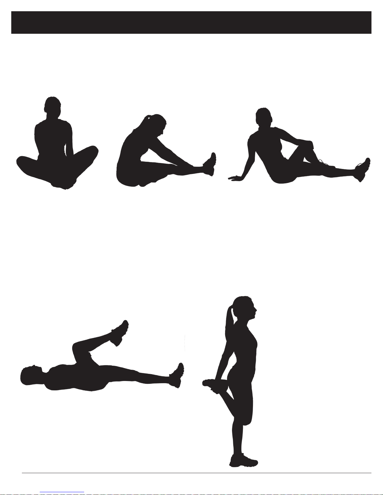
Warm-Up Instructions
Before use, you must read and understand all instructions & warning stated in this Owner's Manual as well as
posted on the equipment.
The following flexibility exercises are provided to you as a means to prevent injury while you are exercising. A
proper warm-up routine decreases the chance of injuring your muscles while you are exercising. Please take the
time to do these flexibility exercises before and after each time you exercise.
Groin Stretch
1. Sit with your knees flexed
and soles of feet together.
2. Hold your ankles and bend
at your hips (keep your
back straight) as you press
your knees toward the
floor with your elbows.
Hamstring Stretch
1. Sit with your left leg extended and bend your right
leg at the knee as you place the sole of your right foot
against the inner thigh of your extended leg.
2. Flex the foot of your extended leg (toes pointed
toward ceiling) and gently bend forward from your
hips; keep your back straight.
3. Reach your hands on your extended leg as far as possible and then switch legs and repeat.
Hip Stretch
1. Lie on your back and raise your right leg as you clasp both hands
under the back of the knee. Keep your left leg straight.
Trunk Twister
1. Sit with your leg extended and
bend your right knee as you cross
your right leg over your left leg.
Your right foot should be flat on the
floor alongside your left knee.
2. Place your left arm on the outside
of your right leg and pull against
that leg while twisting your trunk
as far as possible to the right. Place
your right hand on the floor behind
your buttocks. Reverse leg positions and repeat.
Quadriceps Stretch
1. Stand on your left leg and hold onto
a support with your left hand.
2. Flex your right leg behind you, grasp
your ankle or foot with your right
hand and pull your foot toward your
buttocks. Keep your back straight
and right knee pointed down. Repeat
on the other leg.
2. Gently pull your right leg toward your trunk without raising your
upper body. Switch leg positions and repeat.
BF 620
Page 12

Warm-Up Instructions
Trunk Flexion, Prone
1. Assume the depicted position on your hands and knees. Stretch your hands out in front of you and then slowly start to pull
them back in toward your body as you tuck your chin and arch your back upward.
2. Return to the starting position slowly.
Shoulder Stretch
1. Bring your right hand over
your right shoulder to the
upper back and bring your
left hand under your left
shoulder to the upper back.
2. Try to reach your fingertips. If you are not able to
reach your fingertips, use
a towel as an extension of
your hands and gently pull
one hand toward the other.
Reverse arm positions and
repeat.
Calf Stretch
1. Place both hands against
a wall to aid your balance.
Press the ball of your left foot
against the wall and keep the
heel of the same foot rested
on the floor (make sure your
left knee is bent).
2. Slowly start to straighten your
left knee and you will feel
the muscles in your left calf
stretch. Switch leg positions
and repeat.
BF 620
Page 13

Proof of purchase
Model Number BF 620
BF 620
version: 12-07-2011
 Loading...