


Instructions
for your
BODY BIKE Indoor Cycle
BODY
BIKE
®
I N D OO R C Y C L E
BODY BIKE Basic
BODY BIKE Classic
BODY BIKE Classic Stainless Steel

TABLE OF CONTENTS
Equipment required 2
Introduction 3
Specifications 4
General information 5
Warranty 5
Assembl
y
Unpacking 7
Handlebar 8
Bottom frame 8
Saddle 9
Pedals 9
Maintenance
Cleaning 11
Lubrication 12
Cleaning the posts 12
Adjustment handle 13
Poly-V belt 14
Brake pad 15
Trouble-shooter 17
Index
17
EQUIPMENT REQUIRED
Unpacking
Drill bit
Drill
Bottom Frame
6 mm Allen wrench
13 mm wrench
Saddle
14 mm wrench
Pedals
15mm pedal wrench
Grease
Cl
eaning
Tissue paper or cloth
Spray bottle with water
Soap (only washing-up liquid)
Vaseline oil
Post Cleaning
Clo
th
Vaseline oil
Adjustment Handle
5mm Allen Wrench
Screwdriver
Steel brush
Grease
Brush
Poly-V Belt
10 mm Allen wrench
19 mm wrench
Screwdriver
Measuring device
Brake pad
3 mm Allen wrench
8 mm wrench

BODY
BIKE
®
IN DO OR CY CL E
INTRODUCTION
This manual provides information on the assembly and
maintenance of the BODY BIKE indoor cycle. The manual is
intended for the owners and service people responsible for
cleaning and maintenance.
Before assembling the bike, please read the manual and
prepare the correct tools, see equipment required page 2. When
assembling the bike, we recommend that you follow the manual
step by step.
Maintaining the bike is very important. In the manual you will
fi nd clear instructions on how to maintain the bike.
Over time it will be necessary to replace worn-out parts. You will
fi nd a detailed description of all BODY BIKE’s spare parts on our
website www.body-bike.com. When ordering spare parts from
the local BODY BIKE distributor, please refer to the item number
(P/N no.) in order to make sure you will receive the correct spare
part.
We recommend that you order original parts and accessories e.g.
oil, grease and other materials necessary for the maintenance
of the bike at your local BODY BIKE distributor. For further
information on accessories, please check our website www.bodybike.com
.
3
We wish you the best of luck with your
BODY BIKE indoor cycle

SPECIFICATIONS
Manufacturer:
BODY BIKE International A/S
Pier 6 Nord
DK-9900 Frederikshavn
Denmark
Tlf: +45 9843 9696
Fax: +45 9843 9688
www.body-bike.com
Product description:
Indoor cycle
Length, Width, Height:
Assembled size:
105cm, 60cm, 100cm
Packed size (5 cycles):
120cm, 80cm, 114cm
Weight:
Assembled: 65 kg
Packed weight(5 cycles): 350 kg
Patent held for:
Crank system
Maximum user weight
150 kg (Please note that the max.
pedal load may be lower
)
Materials
Basic version:
Cast iron
Steel and chrome
Plastic (ABS) covers
Quality bearings
Frame: Robot-welded, powder
coated and hardened
Classic version:
Cast iron
Stainless steel
Plastic (ABS) covers
High quality bearings
Frame: Robot-welded, fully
galvanized, powder coated
and hardened
Classic Stainless Steel
version:
Cast iron
Stainless steel
Plastic (ABS) covers
High quality bearings
Frame: Robot-welded,
stainless steel, electro
galvanized.

WARRANTY
A two-year warranty
for the Danish manufactured
BODY BIKE Indoor Cycle:
A two-year warranty against
manufacturing defects, excluding
normal wear and tear, is given for
the flywheel and pulley. A threeyear warranty is given on the crank
and the pedal arms, and a five year
warranty is given against frame
breakage.
Consumable items (such as the poly
V-belt, brake pad, handlebar rubber,
saddle and pedals, etc.) which are
subject to continuous wear and tear,
are not covered by a warranty.
There is currently no warranty
applying to the pedals.
GENERAL INFORMATION
Wipe off the bikes after EVERY use
ALWAYS loosen all handles and
release tension after use
The rubber feet should always be
adjusted to ensure that the bike is
in level
Every other year the rubber feet
should be replaced as the rubber
hardens and becomes unable to
absorb the impact
Pedals should be changed once a
year
DO NOT perform stretch exercises
on the bike, pedals or up against the
bike, except against the strech plate
at the rear end of the bike
DO NOT switch the front or seat post
from one bike to another
DO NOT lift the bike by the saddle
5
ALWAYS RELEASE TENSION AFTER USE

Unpacking 7
Handlebar 8
Bottom frame 8
Saddle 9
Pedals 9
ASSEMBLY

UNPACKING THE PALLET
1) Begin with opening the top of the box.
2) Remove all the unmounted parts.
3) Flatten the box on the floor next to the
pallet.
4) Loosen the two screws mounting the
first bike to the pallet.
5) Lift the bike off the pallet and place it on
the flattened box to spare your floor from
getting marks
.
7

Please note
- Do not overtighten the
screws. They should only be
hand tight.
4: Turn the bike around to mount
the front bottom frame exactly
as the back bottom frame. The
transport wheels must point
away from the cycle.
5: Unscrew the rubber feet a little. Place the bike in the correct
position. Turn them up and down
until the bike stands properly
and it is in level.
BOTTOM FRAME
1: Place the bike as shown on
figure 2 and mount the back
bottom frame. The back bottom
frame is the one without wheels.
Figure 3Figure 1
WASHER
FIBRE
WASHER
METAL
WASHER
Figure 2
BOLT
NUT
2: Screw the back bottom frame
on with the white fibre washer
between the screw and the
bracket. The metal washer goes
between the underneath of the
bottom frame and the nut, see
figure 2.
3: Tighten the screw with your
fingers before using a
13mm
wrench and a 6mm Allen wrench
as shown on figure 3.
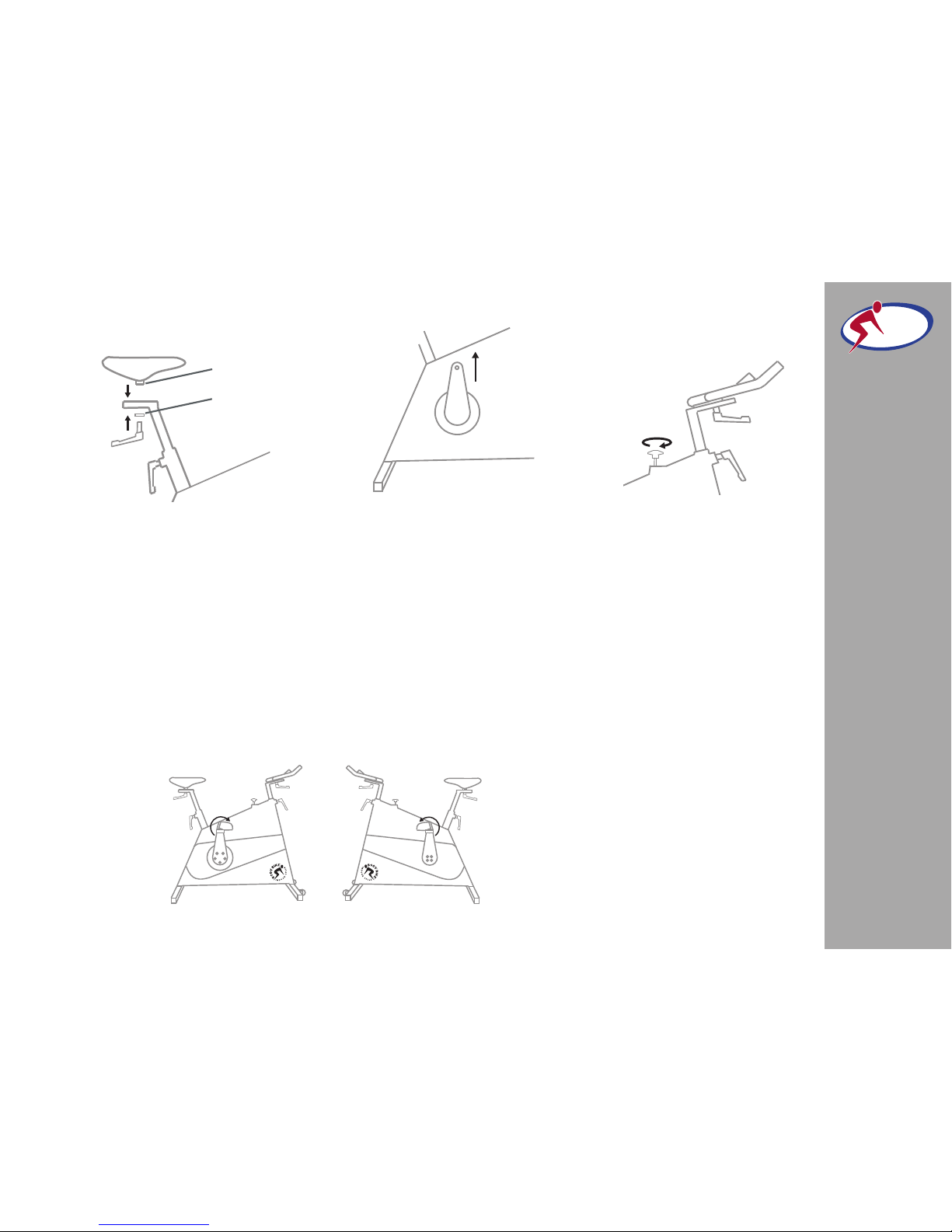
HANDLEBAR
1: Place the handlebar on top of
the front post.
2: Screw an adjustment
handle
(size 32mm) clockwise into the
socket from underneath the post,
see figure 1. Fix the handlebar
completely to the front post by
tightening the adjustment screw
on the side of the handlebar.
ASSEMBLY
BODY
BIKE
®
IN DO OR CY CL E
SADDLE
1: Place the saddle in the track
on the seat post.
2: Secure the saddle with the
remaining adjustment handle,
see figure 4.
To fasten the saddle to the
adaptor and ad
just the tilt
of the saddle use a 14 mm
PEDALS
1: Place the right pedal arm
with the socket pointing upwards, see figure 5.
2: Put maximum resistance on
the brake, so the pedalarm is
unable to rotate, see figure 6.
Figure 6
Figure
7
Figure 5
9
Please note
- the pedals are marked with
R for Right and L for Left side.
- the pedals should always be
screwed on in the direction
of the handlebar, see figure 7.
- make sure that the hole
in the pedal arm is greased
when mounting the pedal.
- start mounting the pedal by
hand as tools will tighten the
pedal at a wrong angle.
3: After tightening by hand,
use a 15mm pedal wrench to
tighten the pedal completely
(45N/4,5kg).
wrench on the bolt marked
with an A on figure 4.
Figure 4
WASHER
A

Cleaning (After every use) 11
Lubrication (When necessary) 12
Cleaning the posts (Every other week) 12
Adjustment handles (Every 3 months) 13
Poly-V belt (When necessary) 14
Replacement of brake pad (When necessary) 15
MAINTENANCE
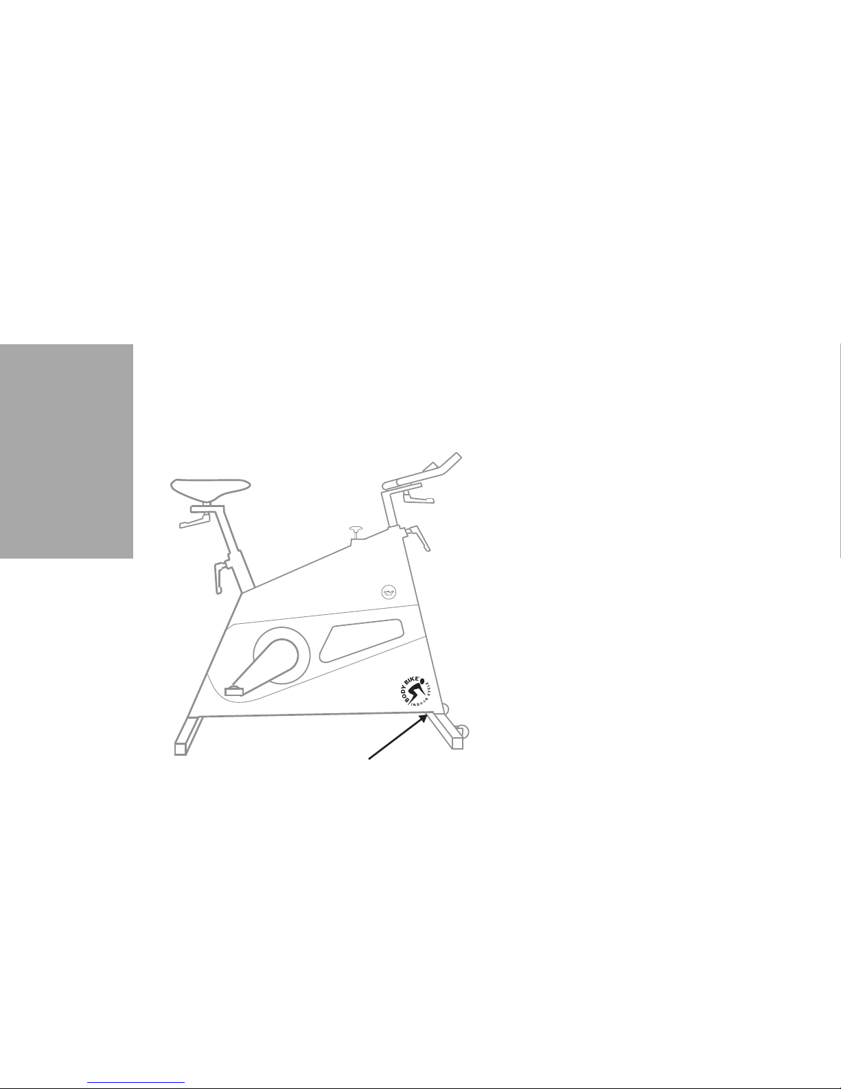
CLEANING
After each workout, wipe the cycle down
with tissue paper.
If the cycle is covered in sweat or dirt, use
water in a spray bottle and if necessary a
tissue with some washing-up liquid.
Remember handlebar and saddle.
NEVER use alcohol or chemicals
To make the cycle look its best, use a cloth
with a little vaseline oil on all parts except
the handlebar and saddle.
Always make sure that the
small hole by
the front bottom frame is not blocked and
allows water and sweat to exit the frame,
see figure 8.
11
SMALL HOLE
Figure
8

LUBRICATION OF THE BRAKE
The cycle needs lubrication if it makes a noise or if the
brake catches too hard. Only use the original BODY BIKE
lubrication oil.
1: Remove the oil plug on the right-hand side of the bike,
see figure 9.
2: Wet a cloth with oil.
3: Wrap the cloth around your index finger and place it
on top of the flywheel while turning the pedals counter
clockwise with the other hand, see figure 10.
4: For control of correct lubrication put your index finger
on the flywheel while turning the pedal to make sure a
thin oil film is covering the whole edge of the flywheel.
OIL PLUG
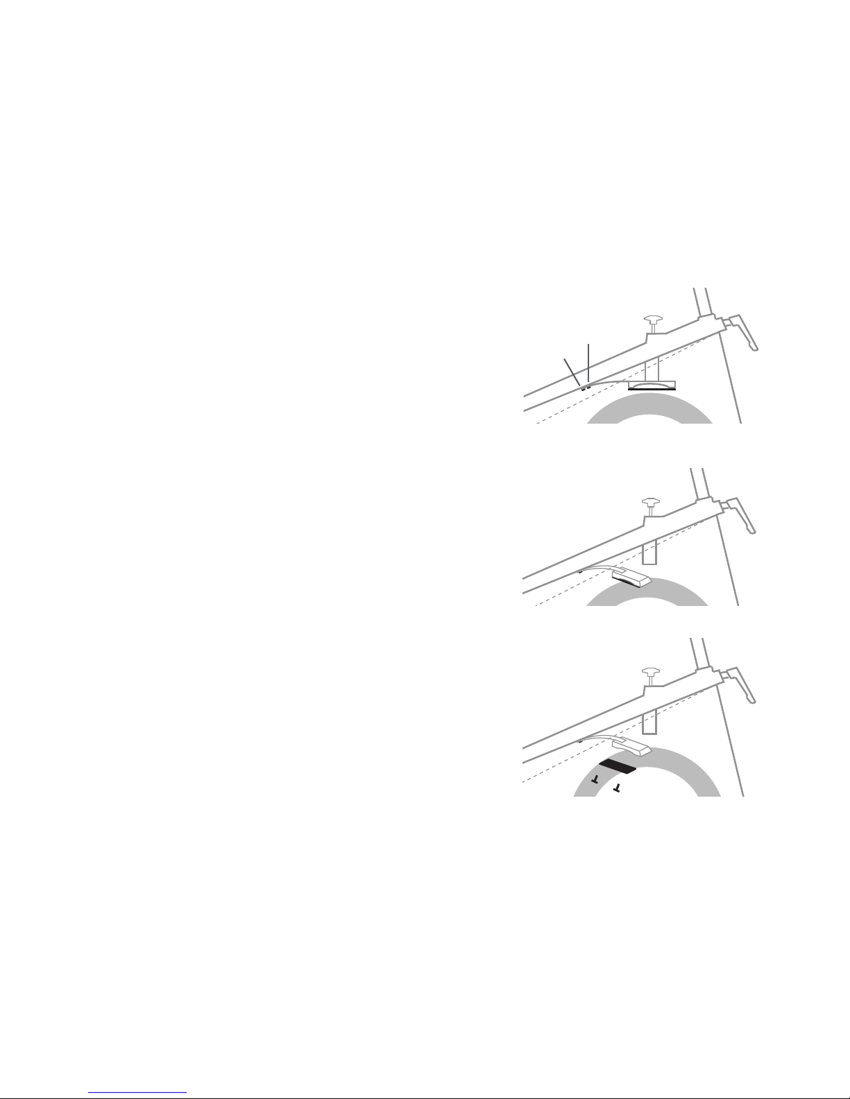
CLEANING THE POSTS
Every other week the posts need cleaning to protect them from sweat etc.
1: Pull out the seat post and the front
post and wipe them clean with an oily
cloth, see figure 11.
If there is a slight sideways play in the
front post you can adjust it on both sides
of the bike with the screws marked
with
an S on figure 11. This adjustment has to
be very subtle in order for the post still
to be able to move up and down.
Figure
9 Figure 10
S
Figure 11
Please note:
The posts should be cleaned every other
week to keep them in good condition

MAINTENANCE
BODY
BIKE
®
IN DO OR CY CL E
ADJUSTMENT HANDLE
Every 3 months the handles need cleaning
and grease to protect the parts from sweat,
dust, dirt and water.
1: Remove the adjustment handle and disas
semble the handle completely into a screw,
a spring, a handlegrip, a main screw and a
brass washer, see figure 12.
2: Clean all the parts thoroughly one by one
using a steel brush.
If the residue is extreme,
a sharp object can be used, for example a
screwdriver.
3: Lubricate the internal parts with grease
before reassembling the handle.
Remember
to lubricate inside the handle as well.
Figure 12
4: Reassemble the handle by inserting
the main screw in the handle grip.
5: The spring is inserted into the top of
the handle and fixed in place with the
remaining screw.
6: Tighten with a 5mm Allen wrench.
7: Add grease to the main screw before
mounting it on the bike.
Please note
Never use a tool when tightening the
adjustment handle on the bike.
By pulling the handle it can be
turned freely.
SPRING HANDLEGRIP MAIN SCREW WASHERSCREW
13

POLY-V BELT
If the belt does not catch hold of the flywheel, it is time
for it to be tightened.
1: Remove the service hatch on both sides of the cycle
with a screwdriver, see figure 13.
2: Loosen the bolts (1) on both sides of the cycle with a
19 mm wrench, see figure 14.
3: Loosen the nuts (2) on the counter bolt on both sides
of the cycle, see figure 14.
4: Use a wrench to tighten the counter bolts (3). On the
right side, the tool should be pulled downwards and on
the left side upwards to tighten.
5: The belt should be tightened to approximately 125
kg/229 Hz. To measure this, a special device can be
bought at your local BODY BIKE Distributor.
SERVICE HATCH
(1)
(2)
(3)
Figure
13
Figure
14
Please note:
The belt should be equally
tightened on both sides.
MAINTENANCE
BODY
BIKE
®
IN DO OR CY CL E
REPLACING THE BRAKE PAD
Even though the brake pad has been well maintained,
in time it will be worn. Figure 15 shows the difference
between a well lubricated pad (left) and a poorly lubricated pad (right).
To get to the brake pad, it is nessecary to
remove the
right side cover from the cycle.
1: Dismount the right pedal arm with an 8mm Allen
wrench.
2: Loosen all the screws and remove them and the bot
-
tle holder.
3: Remove the side cover.
4:
Loosen the two screws holding the brake to the
frame by using an 8mm wrench, but only remove the
Figure 15
6: Tighten the counter bolt (2) on both sides of the bike
again.
7: And tighten the bolt(1) again on both sides of the
bike.
8: Close the bike by fastening the two hatches again.
15
screw closest to the brake, see figure 16.
5: Turn the entire brake down and away from the centre of the
cycle, see figure 17.
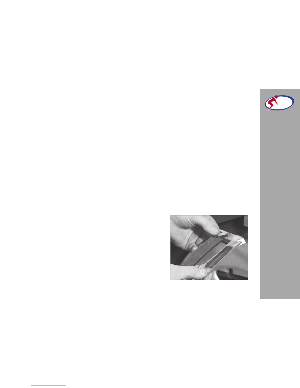
6: Remove the leather pad on the underside of the brake by us
ing a 3 mm Allen wrench. The screws are rarely damaged so these
can be reused, see figure 18.
7: Place the screws in the new leather pad
and mount it by using
the same Allen wrench.
8: Push the brake back in its right position.
9: Mount the brake to the frame by using the removed screw and
tightening the other screw.
10: Clean the flywheel with a cloth and then lubricate, see page
12.
11: Test the system before closing up by putting slight resistance
on the brake and rotate the pedals clockwise by hand.
12: Remount the side covers by screwing in the corner screws
first. Hereafter the remaining screws.
13: Mount the pedal arm by using an 8mm Allen wrench. To se
-
cure the pedal arm, use a rubbermally on the Allen wrench.
Figure 18
Figure 17
LOOSEN
REMOVE
Figure 16

TROUBLE SHOOTER
Correct lubrication?
The cycle is correctly lubricated when the outside
edge of the flywheel has a thin film of oil.
When to lubricate?
- The cycle is beginning to make some noise.
- It is hard to adjust the resistance correctly.
- The brake is beginning to slip when there is heavy
resistance on it.
How to lubricate?
See page 12.
Adjustment handles 13
Adjustment screw 8, 12
Assembly 7- 9
Belt 14
Bottom frame 5, 8
Brake 15
Cleaning 11,12
Cover 15
Crank, warranty 5
Frame 8
Grease 13
Handle 8, 9,13
Handlebar 8
Height 4
Information, general 5
Length 4
Maintenance 11-16
Manufacturer 4
Mounting 7-9
Patent 4
Pedal 9
Poly V-belt 14,15
Post (front and seat) 12
Product description 4
How to keep the cycles in good condition?
It is a good idea to place a board at the exit of the spinning room displaying all cycle numbers. Here people
can write possible problems or concerns arisen during
the exercise. In this way, the people who are servicing
the cycles can get up-dated regularly on how the cycles
are performing, and problems can be identified before
they turn critical.
Rubber feet 5, 8
Saddle 9
Side cover 15
Tools 2
Trouble shooter 17
User weight 4
Wear and tear 5, 17
Weight 4
Width 4
Wheel 8
INDEX
17
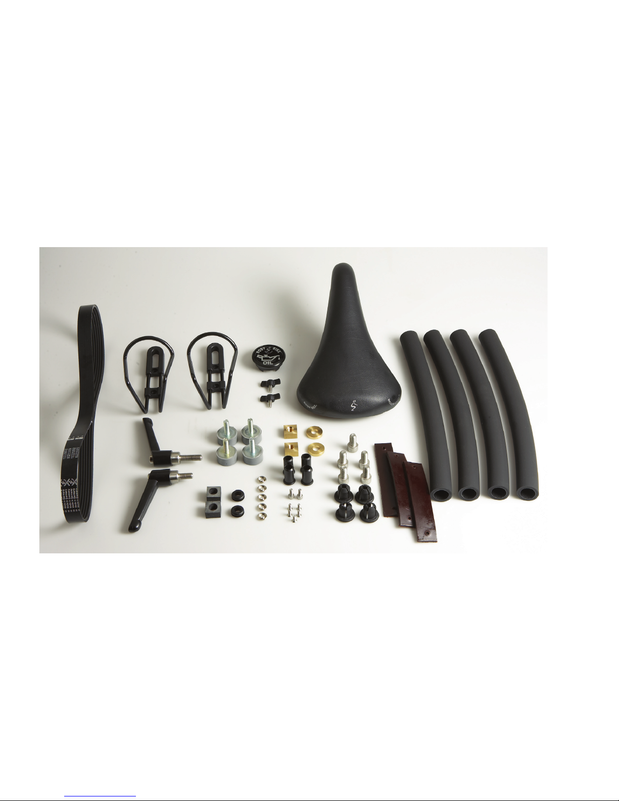
CLASSIC FIRST AID KIT Including a range of spare parts for easy replacement of wear parts.
Item number: 97200000
19
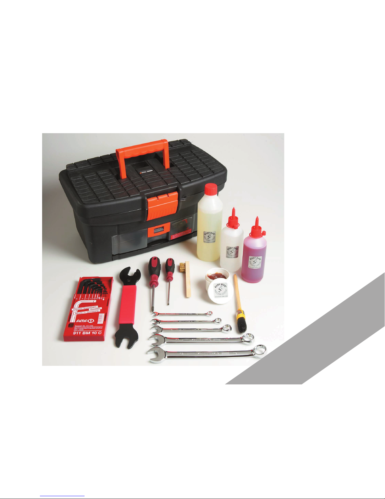
CLASSIC TOOL BOX
Handy tool box
containing a wide range
of tools for maintenance
purposes, e.g. the three
spanners included in the
starter set.
Item number: 92300000
Find spare parts and accessories
on our webpage.
www.body-bike.com
 Loading...