


User Manual for BCL-X Series Laser Machine
1
Laser Engraving and Cutting Machine
User Manual for BCL-X
Series
Jinan Bodor CNC Machine Co., Ltd
Adress: Huaya Industrial Park, Kanghong Road, High-Tech Zone, Jinan,
Shandong, China
ZIP: 250101
TEL: 0086-531-88690020
FAX: 0086-531-88690199
After-sales service:0086-531-88270377
Website:www.bodorcnc.com

User Manual for BCL-X Series Laser Machine
2
Brief Introduction of Laser Engraving Cutting Machine.................................................... 4
I Safety Knowledge..................................................................................................... 4
1.1 Basic Information.................................................................................................. 4
1.2 Optical Security............................................................................................. 4
1.3 Electricity Security........................................................................................ 4
II Equipment Brief Introduction............................................................................... 5
2.1 Instruction of Machine Model&Nameplate...................................................5
1. Model Instruction............................................................................................ 5
............................................................................................................................. 5
............................................................................................................................. 5
2. Nameplate Instruction......................................................................................6
2.2 Equipment Composition................................................................................ 6
2.3 Power Strip.................................................................................................. 15
III Equipment Installation..........................................................................................16
3.1 Installation Preparation................................................................................16
3.2 Installation procedure.................................................................................. 16
3.3 Grounding Connection................................................................................ 20
IV Test Equipment.....................................................................................................20
4.1 Inspect before powering on......................................................................... 20
4.2 Adjust light path...........................................................................................21
V Rotation axis processing........................................................................................28
VI Simple operation instruction................................................................................ 36
6.1 Software installation.................................................................................... 36
6.2 Data line using operation.............................................................................38
6.3 U disk operation...........................................................................................49
VII Equipment's maintenance....................................................................................52
7.1 Daily maintenance....................................................................................... 52
7.2 Water tank’s change and clean.....................................................................52
7.3 Exhaust fan’s clean...................................................................................... 52
7.4 Reflector’s and lens’ clean........................................................................... 52
7.5 Guide rail's clean......................................................................................... 53
7.6 Light path's examination..............................................................................53
VIII CO2 glass laser tube's precautions for use.........................................................53
IX Common Breakdown Maintenance...................................................................... 54
Appendix 1................................................................................................................ 56
After-sale warranty of Laser Engraving Cutting Machine》........................ 56
《
Appendix 2................................................................................................................ 59
Cutting and engraving parameters of laser tubes...............................................59
Postscript................................................................................................................... 62
After-sale warranty of Laser Engraving Cutting Machines》.......................................62
《

User Manual for BCL-X Series Laser Machine
3
Preface
Thank you very much for your trust and purchasing our Products. We can provide perfect
after-sale service and solutions. Please keep this manual and other attachments carefully,
in order to guarantee the equipments safe running.
This manual is only applied to our company’s standard machines. With regard to special
customized machines, please read other reference material carefully.
This manual is written to demonstrate the issues about working principle, installation,
operation, failure removal, transport,storage, maintenance etc. Please read the manual
carefully, if you use the equipment the first time.
For quick and efficient using this equipment, the user should have qualifications as
below:
1. The user needs to know basic computer professional knowledge, and can operate
related editing and drawing software, such as Coreldraw, Photoshop, Autocad and so on.
2. The user should have basic optical knowledge and related electromechanical device's
maintenance knowledge.
3. Before starting the equipment, make sure this equipment's operation procedure is
known well and operate accordingly.
Because of equipments continuous updates, there may be some difference between your
equipments and equipments shown in the manual in some aspects. We apologize for the
convenience.
If you have any good suggestions or doubts, please log in our website
www.bodorcnc.com to leave a message or call us directly.
After-sales' Service:0086-531-88270377

User Manual for BCL-X Series Laser Machine
4
Make sure that the operator is being trained before operating the machine.
Operator must be aside the machine during machine working. Never leave the
Before connecting electricity, please check carefully the requirements on the
Without our permission, please don't dismantle electrical apparatus elements on the
Brief Introduction of Laser Engraving Cutting
Machine
I
Safety Knowledge
1.1 Basic Information
machine alone in case to cause unnecessary loss.
1.2 Optical Security
Our laser equipment adopts the forth laser tube.Length of laser beam is 10.6μm. During
machine working, we recommend people related to wear authorized laser safety goggles.
Do not stare at the laser beam or anything beam reflected.
1.3 Electricity Security
equipment's name plate, such as power,working voltage and so on.
equipment, especially do not touch laser power and laer tube during machine
working. Because the equipment has fatal voltage when working, and danger can
still exist after disconnecting electricity.
1 Harm
Various potentially dangerous substance can be eliminated through ventilation system
during plastic material cutting. If smog or smell is too heavy, gas mask is needed.
2 Other Harm
Out of security consideration, equipment modification is forbidden without the
permission from the Manufacturer.

User Manual for BCL-X Series Laser Machine
5
1.Model Instruction
Machine Serial
BCL:
Bodor Cutting
Laser
BML
:
Bodor Marking
Machine Working Area:
0503: 500mm×300mm
0605:600mm ×500mm
1006:1000mm×600mm
1309: 1300mm×900mm
1610: 1600mm×1000mm
… ……
Model Introduction
:
M: Mini Machine Serial
X: Standard Machine Serial
B: Bed Machine Serial
FB: Fiber Laser Cutting
Machine Serial
YB/YT: High Power Metal
Cutting Machine Serial
FP/BM: Fiber Laser Marking
Machine Serial
Other Attachments:
U- with up-down working
table
F- automatic focus/fiber
generator
H- high speed guid rail
V- vac-sorb
A- auto feed
CCD- automatic logo
positioning cutting machine
P- separable style stone
engraving machine
S- screw machine
R-RF tube
G-glass engraving machine
D-die board cutting machine
II Equipment Brief Introduction
2.1 Instruction of Machine Model&Nameplate
※※※一※※※※一※※
BCL1309X means standard serial laser cutting machines with 1300mm x 900mm
working area and up-down working table.

User Manual for BCL-X Series Laser Machine
6
2.Nameplate Instruction
A.Machine Shell B.Drive System C.Optical System D.Control System E.Spare Parts F. Tool
Laser
Machine
Machine
Shell
Drive
System
Optical
System
Control
System
Spare
Parts
Tool
Box
This number is only for each machine
This serial equipment is vertically installed in the middle of the transmission shaft, which
can make speedy and stable cutting and engraving.The nameplate of machine is in the
right-back side. You can read the relevant information on it. It is not accepted for
anybody to change or remove this nameplate.
2.2 Equipment Composition
Declaration: Due to different models or new updates in products, there may be some
difference in appearance or some partial detail. Specific equipment is subject to
final product.
2.2.1 Composition of full set machine
Box

User Manual for BCL-X Series Laser Machine
7
Working
Side
Front Door
Transom
Carling
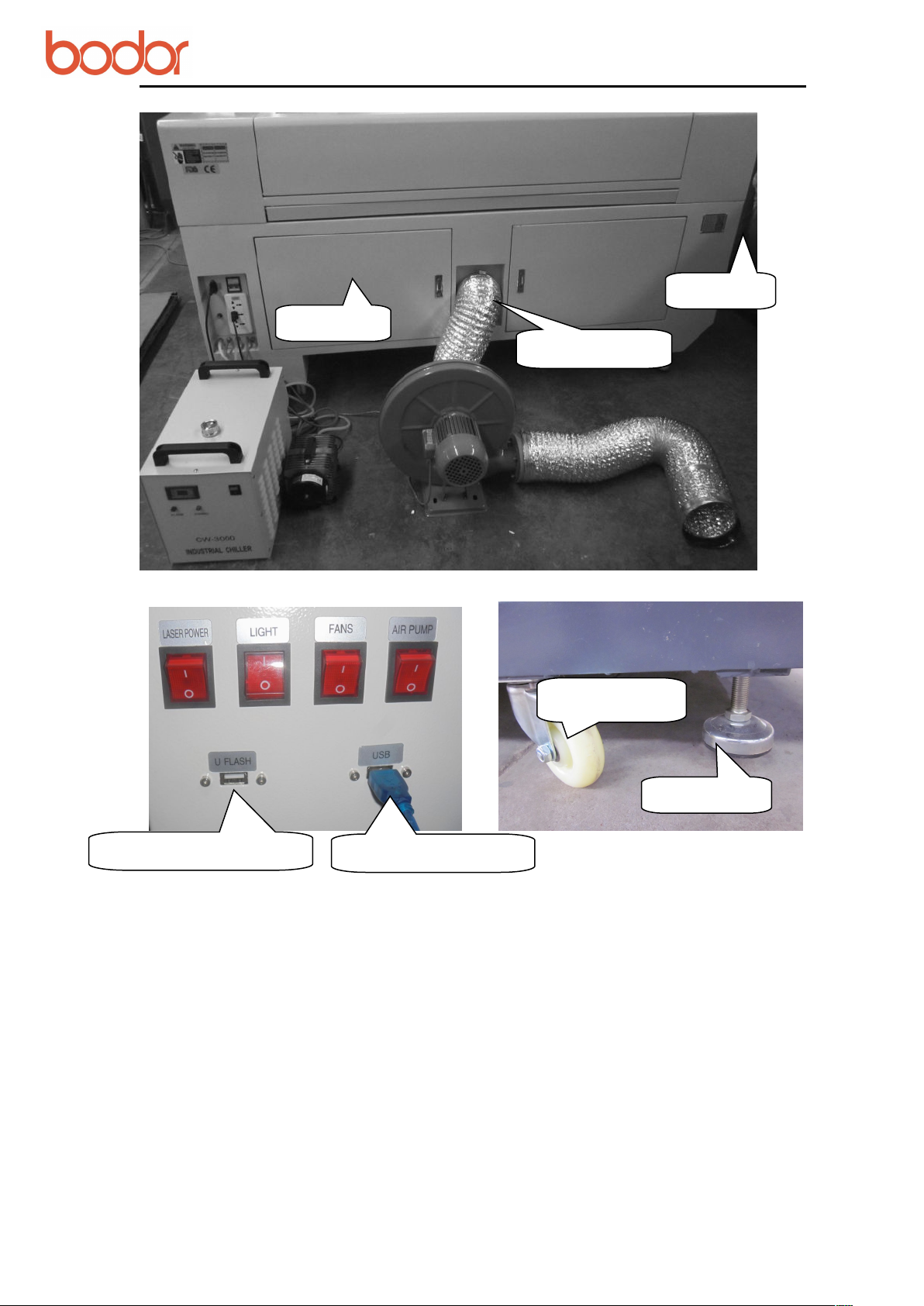
2.2.2 Machine Shell
Right/Left Shield; Side Door; Up Cover; Transom(X Axis); Carling (Y Axis);
Working Table.
User Manual for BCL-X Series Laser Machine
8
Back
Smoke
Name
Universal
Foot
USB Flash Interface
Computer Interface
2.2.3 Drive System:
Y Axis:

User Manual for BCL-X Series Laser Machine
9
Guide Rail
Girdle
48 tooth
Synchronizin
g Wheel
Motor
Transmissio
24 tooth
Synchronizing Wheel
belt
Guide Rail
Belt
Mot
Pinion Stand
Endless-belt
Couple
24 tooth
Synchronizing
48 tooth Synchronizing
Wheel
X Axis:

User Manual for BCL-X Series Laser Machine
10
Laser Tube
Reflection Mirror
Laser outlet
Cathode rays
Reflection Mirror frame
Laser Tube Socket
2.2.4 Optical System
Attention:
The laser tube is fragile. It should be taken slightly. Water inlet of the laser tube should be
in the lower place, and water outlet be in the higher place(reci laser tube), so there won't
be any bubble. The laser tube socket should be installed with even force which can just
make the tube secure. Do not overexert, it may crush the laser tube.
Attention:
The front surface of reflection mirror should be faced to the laser outlet.

User Manual for BCL-X Series Laser Machine
11
High-tension cable
High-voltage insulation protective jacket
Water-in
Water flow direction
Red dot position
Air compressor
control valve
Focus Lens
3rdReflection
Mirror
Focal length adjusting
tool
Attention:
The working-voltage of high-tension cable can be higher than 100,000V.There can be
strong static electricity even when the power was cut-off in short time. Please do not
touch the cable directly.
Attention:
Before working, please adjust the focal length. Put the focal length in the middle of
working material and laser outlet before working. Convex surface should be faced to working
material when installing focus lens.
Installation picture of RECI laser tube

User Manual for BCL-X Series Laser Machine
12
2.2.5 Control System
There are some difference in the control system for different models.Specific product is
subject to real object.
Bodor's control system is as below:
Leetro control system;
Ruida control system;
Bodor control system.
Leetro control panel Ruida control panle
Leetro control board Ruida Control Board

User Manual for BCL-X Series Laser Machine
13
Filter
48V Switch power
X Axis Motor Drive
Y Axis Motor Drive
Z Axis Motor Drive
System card board
Relay
DC24V and 5V
Power
Laser
Power
Emergency
Switch
Ammeter
Potentiometer
Start Button
2.2.6 Spare parts
Water Chiller Exhaust fun Air compressor

14
2.2.7 Tool Box
Certificate
Approval
Data
Power
Limit Swith
Double-sided
Adhesive Tape
High-tension
Adhesive
U Disk
CD
Water/Air Tube
Fork
Wrench
Hexwrenc
Shove
l
Focus
Dimming
Block
User Manual for BCL-X Series Laser Machine
Attention: There can be some difference in toolbox for different models. Specific parts
are subject to real objects.
Proximity Switch&Inching Switch
Shovel Blade Usage Focus Block Usage

User Manual for BCL-X Series Laser Machine
15
Air Switch
Power
Interface
Abalone
Socket
Ground
Air-tube
Interface
Fuse
Water Chiller
Signal Line
Outlet Connecting
Water Chiller
Inlet Connecting
Water Chiller
2.3 Power Strip

User Manual for BCL-X Series Laser Machine
16
III Equipment Installation
3.1 Installation Preparation
3.1.1 Preparation for workplace
Make sure the working area is dry enough. And any electromagnetism, strong power,
pollution is forbidden. Temperature of working environment should be 10℃ to 38℃,
humidity should be 10- 90%. AC 220V±10%, 50HZ, resistance to ground less than 5Ω.
3.1.2 Preparation for operator
We demand the operator must be professional technician. If the users want to install the
equipment on their own, they need to have training from our technicians and completely
master the knowledge of installation.
3.1.3 Preparation for tools
There is already a tool box with this machine. Besides, multimeter and screwdriver and
other detection tools are needed.
3.1.4 Other preparation
The users need to prepare relevant material,including purified water or distilled water for
water chiller, power strip, computer,pipe for discharge smoke, sample material, etc.
Attention: The users need to accompany all the time when our technicians install the
equipment. The users need to grasp the skills of installation and commissioning which
are the part of training.
3.2 Installation procedure
3.2.1 Package of laser tube
Laer tube package:
In case of damage during transportation or outside force, the tube is packed with sponge.
And two ends of tube are sealed with zip lock bag to prevent the mirror from pollution or
scratch. Finally, the tube is built up with sponge supports to prevent tube have direct
contact with surrounding.

User Manual for BCL-X Series Laser Machine
17
1.Take off the screw from the two laser support which are used for fitting the laser tube.
2.Put the outlet(low-tension part) of the laser tube on the base facing to the first reflected
3.Buckle the upper part of the laser tube support, tighten the screw, connect the
4.Fix the laser tube.
Keep the laser tube outlet clear in case of front mirror breakdown. The broken
Fix the laser tube with proper strength. Larger strength will broke the laser tube.
Keep the laser tube water inlet in the lower place, and the water outlet in
Water tube joints must be connect well avoiding water leaking. Water tube must be
Handle laser tube carefully when installing.High-tension wire and cathode rays
Laser tube devanning:
Open the carton box, take out the laser tube. Both hands hold the middle of the tube; take
off the sponge supports; take off the packing sponge; take off the zip lock bag. Then
inspect whether the tube is intact.
Attention: It needs as least two persons when unboxing. Handle the tube with care.
3.2.2 Installation of Laser tube
Move the equipment to the back place, so as to install the laser tube easily.
The laser tube is installed in the back of crossbeam.Open the laser tube protective cover.
You can see two laser supports, two water pipes, a black color low-tension line and a red
color high-tension line.
Low-tension line High-tension line
Laser tube installation:
mirror.
high-tension&low-tension line and outlet&inlet water tube.
Attention:
damage caused by improper operation, will not be in Bodor's range of protection.
the higher place(in the upper section of laser tube). Come in from the bottom, out
from the top as shown in the above picture.
straightened.
should be fastened enough.Water inlet should be in the bottom and water outlet in the
top. Make sure there is no air bubble in the laser tube. Use even force on the two
sides when pushing laser tube sockets to fix the laser tube. Do not use too much
force avoiding the damage of laser tube.

User Manual for BCL-X Series Laser Machine
18
When working, the water must flow from the high-tension to the low-tension.
When the power is on, the bubble in the tube can be removed by extruding the water
When machine is working or shut down, please do not touch the high-tension line. It
display
Water inlet
green indicator
light
Water-outlet
Water-in
Alarm
Power line
Ship type switch
Water-out
Alarming line
3.2.3 Installation of Water Chiller
▲ First take down the cover of water inlet on the top of the chiller. Pour purified water or
distilled water into the water tank until it is full.
▲ Then complete the connection of water cycle pipelin by connecting the water outlet of
the chiller with the water inlet of the machine, and the water inlet of it with the water
outlet of the machine.
▲ Finally, connect the holding wire and the water chiller power line.
Pressing the rocker switch after electrifying the chiller, you can hear sound like
"didi...".Then the water in the tube will flow from high-tension terminal to low-tension
terminal. Then the green indicator light on water chiller will be on. The system works
well if the alarm does not ring.
Attention:
Otherwise, it may damage the laser tube.
pipe or turning the laser tube.
may still have high power and may threat to life.
Chiller installation: water-inlet in the top side, water-outlet under the back below side
3.2.4 Installation of Exhaust Fan and Air Pump
Installation of Exhaust Fun
Connect the air inlet of the fan with exhaust port by the air duct and screw tightly with
spanner. Then connect the outlet of the fan by the other air duct and lead it out of the
room. The installation is as shown in the below.

User Manual for BCL-X Series Laser Machine
19
Screw tightly
with spanner
Installation of Air Pump
Insert the silicone tube into the air-inlet by an air tube. Then connect the power and make the smooth
air-out of the air entry in the leaser head as shown in the below picture.
Air pump (air compressor) is very important in the system. High-pressure air sprays from
the light outlet of laser head through air tube. On one hand, it can keep the focus lens
clear enough. On the other hand, it can prevent working material from burning. Please
make sure the rubber tube is intact during machine working. Otherwise it may cause
burning of the materials.

User Manual for BCL-X Series Laser Machine
20
Name Plate
Water Chiller
Air pump
Exhaust Fun
3.2.5 Installation of accessory
3.3 Grounding Connection
Grounding requirements for the equipment are very strict. Your local electric system
must meet the local electric security standard.
L : 220V Live line; Phase line
N : Zero Line, compose the electric system together with phase line
E: Grounding line, connect every grounding part of electricity consuming
accessories,resistance to ground should be less than 4 Ω
Attention
Nonstandard grounding may lead to high failure rate and other security accidents. All
these are not in the range of Bodor's protection.
:
IV Test Equipment
4.1 Inspect before powering on
Before powering on, please inspect and make sure all electric wire terminals are intact.

User Manual for BCL-X Series Laser Machine
21
Then pull the laser head to check whether it can move smoothly and move the crossbeam
front and back to confirm whether it can be noise free.Power on when everything is ok.
4.1.1 Boot Process
Open:
Air-break switch "ON"---> Roll emergency switch ---> Press switching button---> Open
rocker switch of water chiller---> Open the rocker switch of air pump, air exhaust and
laser tube.
Shut down:
Shut down the rocker switch of air pump, air exhaust and laser tube--> Close the rocker
switch of water chiller ---> Press emergency switch ---> Air break switch "OFF"
4.1.2 Test Running
Power on. Then press the direction key on control panel to test whether laser head can
move normally, whether X axis beam have any noise, whether each device can work
properly and whether the movement and process back to the origin is normal. If
everything is ok. Then you can proceed the below step: Debugging of laser path.
4.2 Adjust light path
4.2.1 Test laser
After the equipment is powered on, please make sure the water flow direction in laser
tube is from high-tension terminal (red line) to low-tension terminal (black line); inlet
and outlet water pipe and electric line connect properly. Most importantly, be sure there is
no bubble in the tube.
Next, stick one acrylic block on the first reflection mirror, press the "Laser" button on
control panel to test whether there is laser out of the tube or there is facula on the acrylic
block. If there is no facula or weak light, then you need to check whether you have set
the potentiometer on the max value, or whether the water chiller is connected in right
way. If there is still no light, then there may be some defect of laser tube or laser power
supply.
User Manual for BCL-X Series Laser Machine
22
4.2.2 Adjust light path
The laser path is debugged OK before shipment. While there may be deviation of laser
path during long time transportation. You need to debug the laser path if it happens.
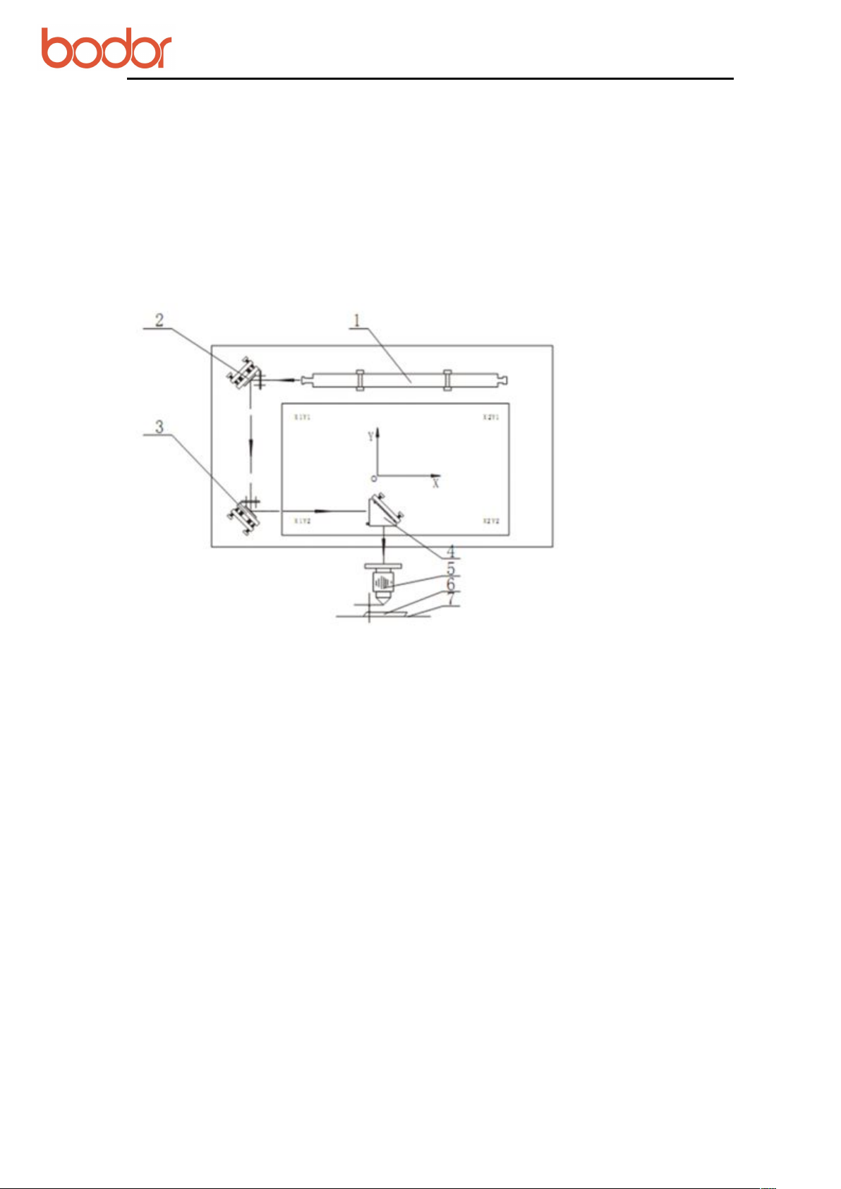
Laser Fundamental Diagram as below:
Optical system consists of a laser tube, 3 reflection mirrors, 1 focus lens, a laser head and
red dot position system.
1. Laser tube 2. First Reflection Mirror 3. Second Reflection Mirror 4. Third Reflection
Mirror 5. Focus Lens 6. Working Material 7. Work Table
Laser is reflected to first reflection mirror through front mirror of laser tube, then goes to
second and third reflection mirror, and finally then reaches the working table through
focus lens. Finally reach on the work table. In fact, laser path is the process of several
reflections and focus. If screws loosen in the process, there can be laser path deviation.
The laser will not emit from laser outlet.
4.2.2.1 Necessities for adjusting laser path
Laser adjusting block, double faced adhesive tape, focal length block, shovel blade,
needle-nose pliers
4.2.2.2 Methods for adjusting laser path
In principle:
Adjust the reflected facula into a dot, then move the facula into the center by adjusting
the position of laser tube.

User Manual for BCL-X Series Laser Machine
23
Paste a 3mm acrylic on the first reflection mirror.
Press pulse button.
Check whether the facula shoot is on the first reflection mirror. If it is not on the first reflection
2.Adjust second reflection mirror
Paste a 3mm acrylic on the second reflection mirror. The second reflection mirror is
Press the direction button on control panel to make the crossbeam move to the
Then press pulse button and check the position of the shoot facula.
Press the direction button on control panel to make the crossbeam move to the
Then press pulse button, do not move the crossbeam and check if the facula is
Before adjusting, make sure the light outlet of laser tube
should be identical with the hole of laser head. Laser from
laser tube should be in the back of the center in the mirror
which can make the laser path reflection better. Adjusting
method: adjust the installation position of laser tube or first
reflection mirror mount.
Laser shoot from laser emitter goes through first, second and third reflection mirror successively and
reaches to work table through focus lens. Its working principle is to get the best engraving and cutting
effects after several reflections and focus. If laser path is not smooth, it may damage laser generator,
reflection mirror, focus lens etc. Please re-adjust the laser path if it is not correct.
Detailed procedures of adjusting laser path are as below:
1. Adjust first reflection mirror
The best effect is that the facula from laser tube is in right of the center.
Adjusting method:
mirror, please adjust the installation position of laser tube or mirror mount.
The best effect is that the facula reflected by the first reflection mirror is in the right of
the second reflection mirror center.
Adjusting method:
in the far left of the crossbeam.
nearest place near first reflection mirror.
furthest place near first reflection mirror.
identical with the facula from near place. If they are not identical, please adjust 3
screws behind the back of first reflection mirror, until they are identical. After they
are identical, move the crossbeam front and back to check if they are still identical in
the right of the mirror. If not, please fine-tune 11,12.13 screws of mirror base and
turn the second reflection mirror mount.
Attention:

User Manual for BCL-X Series Laser Machine
24
No.1 Screw
Testing method when laser is reflected from first
reflection mirror to second reflection mirror:
Move the second reflection mirror on Y axis at the nearest
and farthest position from first reflection mirror.
From the first reflector to second reflector, the laser beam
should be fell on the same point from both nearest and
farthest position to the first reflector.
Upper--please adjust No.1 screw;
Lower--please adjust No.2 and No.3 screw;
Left—please adjust No.2 screw;
Right—please adjust No.1 and No.3 screw.
No.2 Screw
No.3 Screw
If light on the same point is not on the right side
of the center, please adjust No.11,12,13 screw to
relevant position ( generally don’t need to
require adjustment).
No.11 Screws ( two screws)
No.12 Screws ( two screws)
No.13 Screws ( two screws)
Optical system of bed is in the inside of gantry. The adjusting of second reflection mirror
is easier. Just adjust the first reflection mirror.

User Manual for BCL-X Series Laser Machine
25
3.Adjust third reflection mirror
Paste acrylic on the inlet of laser head. Move laser head to the leftest of the beam by
Move the laser head to the furthest right of the beam by direction button on the panel
After they are identical, please move laser head left and right to check if they are still
No.23
No.21
No.22
No.11 screw (Double)
Second reflection
The best effect is that the facula reflected by the second reflection mirror is upper to the
center of the third reflection mirror.
Method:
left-right direction button on the panel. Press ‘pulse’ button and check the position of
the facula.
and press pulse button. Do not move the laser head and check if two faculas from the
furthest point and nearest point are identical. If they are not identical, please adjust 3
screws(21,22,23) on the back of the second reflection mirror until they are identical.
identical on the mirror center. If not on the mirror center, please adjust the height of
laser tube or 3 screws(1,2,3) on first reflection until the faculas are on the mirror
center.

User Manual for BCL-X Series Laser Machine
26
4.Adjust focus lens
Adjust the lens cone to focus. Paste double-sided adhesive on the laser tube outlet.
Press pulse button and check if the facula is on the center as shown in picture A. If
If there is no light on the outlet, please take off the cone head of lens cone.Then
Repeat these above procedures until the facula is on the center.
Third reflection mirror
Up
Right
Low
Left
Accordingly, from second reflection mirror to third
reflection mirror, laser should fall on the same upper side of
the center slightly.
Upper—adjust No.21 screw; lower—adjust No.22,23 screw;
Left—adjust No.22 screw; Right—adjust No.21,23 screw.
If light on the same point is not on upper side of
the center slightly:
Left or Right -- adjust No.1,3 of first reflection
mirror
Upper / lower -- adjust the position of laser tube.
Third reflection mirror
Up
Right
Left
Low
The best effect is that the facula reflected by third reflection mirror is on the center
of outlet.
Method:
not, please adjust 3 screws on third reflection mirror.
paste double-sided adhesive tape on the laser tube outlet. Press pulse button and
check if the facula is on the center. If not, please adjust 3 screws of third reflection
mirror until the facula is on the center. Then reinstall the ,
Attention:
You need to adjust the laser path after cleaning or changing mirrors.
Deviant optical path can affect cutting effects and quality, even damage focus lens.

User Manual for BCL-X Series Laser Machine
27
put a double-sided adhesive tape on the outlet of
the laser head, take left hand side as left, right
hand, right;laser tube side, front and people where
No.31 screw
No.33 screw
No.32 screw
Laser beam spot should be in the center of the
outlet. Please refer to picture A. If not, please adjust
No.31,32,33 screws.
Left -- please adjust No.32 screw;
Right -- please adjust No.31 and 33 screw;
Front -- please adjust No.32 and 33 screw;
Front
Right
Back
Left

User Manual for BCL-X Series Laser Machine
28
Front
Left
Right
Back
Adjusting
Lens cone fastening
Focal length adjusting
Red dot
Picture A
Focus test is as shown in picture A:
First paste double-sided adhesive tape on outlet, press pulse button and check if the
facula is on the center of outlet. If not, please adjust 3 screws of laser head.
Attention:
Laser is invisible light but can do harm to human body. Please keep away from the laser
path when debugging. The operator must master the basic knowledge of laser machine.
4.2.3 Trial Processing
Put working material on the work table.
After laser path is adjusted, rotate screws of lens cone to the height of focusing clockwise.
After adjusting focus, lock screws of lens cone anticlockwise. The move the laser head to
specified location. At last open software, make or transfer pictures, set working
mode&speed&efficiency.
Then you can work the material after nominating downloaded files.
Take following picture as a reference.
V Rotation axis processing
1. Electrical appliance installation

User Manual for BCL-X Series Laser Machine
29
1.1 Rotation axis connect
Fix rotation axis
Draw out aviation connector of the drive.

User Manual for BCL-X Series Laser Machine
30
Connect the aviation connector of rotation axis with the drive’s aviation connector
1.2 Reset on power
Power on the machine, then touch the limit switch of Y axis by metal manually to assist
equipment resetting work when resetting the machine as shown in the picture:

31
2. Software operation
2.1 Software set
User Manual for BCL-X Series Laser Machine
A. Open the software, click ‘File’ ---‘Vendor settings’, enter password ‘rd8888’ and log
on.
B. Press ‘Read’, then close dialog box.

User Manual for BCL-X Series Laser Machine
32
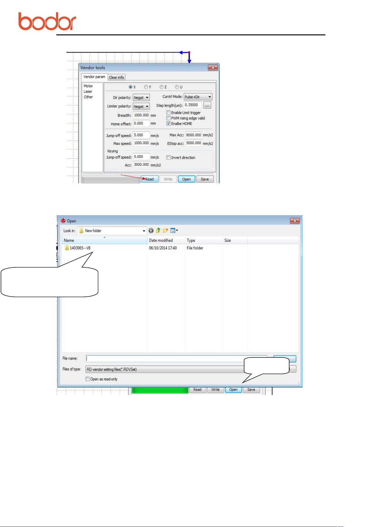
C. Choose “User” on the right side of software, click ‘Read’ and set parameters as shown
in the below picture.
After changing parameters, click ‘Read’.
Attention: Record the original parameters before changing them. Reset them when you
don’t need rotation axis.

User Manual for BCL-X Series Laser Machine
33
(1) Open ‘Output’ menu. Input ‘10000’ in ‘Circle Pulse’ and ‘65’ in ‘Diameter’ as shown
(2) Draw 20mm line on the software
2.2 Pulse calculation
‘Circle pulse’ is changing along with the diameter changing of rotary products.
Calculation formula:
Realistic pulse=(theoretical pulse*theoretical length)/ realistic length
Example: engrave 20mm line on the bottle bottom of 65mm diameter.
in below picture.
Attention: select ‘Output’ and tick ‘ Enable rotate engrave’
‘Diameter’ means the diameter of working material.
On the software, draw 20mm line and set cutting parameters: recommending speed ‘15’,
maximum power ‘15’, download.

User Manual for BCL-X Series Laser Machine
34
(3) Paste a double-sided adhesive tape along the surface of working object.
(4) Place the rotation axis in right position, adjust the position of the bottle. Pull the
beam and make the laser head upon the bottle.
Attention:
Confirm the position of rotation axis placing
:
Press direction button on the panel. If the direction of driving wheel in rotation axis is
opposite to the button-pressing direction, it is the right position. The working shape is
mirror image if the position is wrong. Just turn 90 degrees of rotation axis.

User Manual for BCL-X Series Laser Machine
35
(5) Start to work after adjusting focus
(6) Measure the length of cutting line
(7) Change Circle Pulse
Measuring length is 16.5mm and is not identical with 20mm on software. So Circle
Pulse(10000) is not correct.
According to the calculation formula---{10000*20}/16.5=12121, you can get the actual
pulse 12121.

User Manual for BCL-X Series Laser Machine
36
Input the calculated pulse and the object diameter.
3. Attention
When you don’t use rotation axis, please set the parameters in “User” to original
parameters and remove tick before .
Tips: The placement direction of rotation axis can affect cutting effects. A wrong
direction placement can result in a reverse effect.
VI Simple operation instruction
Before operation, please electrify the equipment, then connect the machine USB and
computer USB with USB data line.
6.1 Software installation
A. Double click on ‘RDCAMSetup6.exe’ in the disk catalogue. Below dialog box will show
up.

User Manual for BCL-X Series Laser Machine
37
B. Click【Install】button. Installation interface shows up after unzip and copy operation.
C. Click . The following dialog box shows up.
D. After confirming USB data line is connected well, click“OK”.
The following dialog box shows up.

User Manual for BCL-X Series Laser Machine
38
E. After installing USB drive, click to install software.
After that, the following dialog box will show up and indicate that the software has been
installed successfully.
F.After finishing all installations, click【 】to end up installation process.
The user may need to install some different softwares (install external software while
installing LaserWork). So after finishing all installations, the dialog box cannot close
automatically. The user can end up installation by clicking 【 】button.
6.2 Data line using operation
Before operation, the machine has been started. All accessories such as water chiller and
pump can function well.
6.2.1 Read parameters
Different machines have different versions.
The purpose of reading parameters is to match “Supplier Parameter” and “User
Parameter” in main board with parameters in software.

User Manual for BCL-X Series Laser Machine
39
A. Click“File”, then open“Vendor settings”.
B. Input password “rd8888”.
C.After entering interface, click“read”.

User Manual for BCL-X Series Laser Machine
40
D. Click“user”as shown in the following picture.
Click“read”.
Attention: if changing main board or parameters, please first go through“read”. Then find
parameters of CD or U disk and go through“open”and“write”.
User Manual for BCL-X Series Laser Machine
41
Click it
File folder named by
machine serial number
E. In the U disk or CD along with the machine, find the file folder named by machine
serial number.
F. After that, “CHANGJIA.RDVSet”file shows up.

User Manual for BCL-X Series Laser Machine
42
Click it
G.After opening it,“Import param success”shows up.
H. Click “
” as shown in the following picture.
用户
According to the supplier’s setting mode, follow the sequence of“read
write”to import user parameters.
“
”—“
open
—

User Manual for BCL-X Series Laser Machine
43
I. After importing parameters of the supplier and user, close the software.
Reopen the software, you can use it normally.
6.2.2 Make simple pictures&Set picture layers
A.In the software, choose “Rectangle”and draw a simple square. Then modify the size.

User Manual for BCL-X Series Laser Machine
44
Modify size
B. Click “script”.
Click once in the drawing zone.
In the dialog box, edit text and click “OK”button.

User Manual for BCL-X Series Laser Machine
45
Layer
C. After choosing text by frame, select picture layers.

User Manual for BCL-X Series Laser Machine
46
Click it
6.2.3 Set working mode
According to cutting material, set power and speed. (Cutting parameter sheet can be for
reference)
6.2.4 Download file
Click “DOWNLOAD”.
Name the file.
Click “OK”.

User Manual for BCL-X Series Laser Machine
47
6.2.5 Machine operation
1.On the machine, find downloaded file by pressing “file” button as shown in the picture.
2.After finding named file, press “Enter”button.
3.put cutting material well and adjust focal length well.

User Manual for BCL-X Series Laser Machine
48
Position button
Start
4.find the right place ,press “origin”button to frame cutting area. Then press “start”button.
Then you can see the machine is cutting material as shown in below picture.

User Manual for BCL-X Series Laser Machine
49
Save as
offline file
6.3 U disk operation
Same operations with data line will not be listed again.
1.After setting power, speed and cutting method, click“ Save as offline file” and
shows dialog box. Name the name of the file. Then click and save “USB drive”.
2.In the file location, find the file and save it to U disk.
3.Insert U disk to the interface of the machine.

User Manual for BCL-X Series Laser Machine
50
4.Choose
“读U盘文件”
and press
“确认”
button.
5.After choosing the file, then choose“copy to memery”and press“OK”button.
Below picture will show.
Attention: if there is a file in the machine which has the same name as the file in U

User Manual for BCL-X Series Laser Machine
51
disk,the copy operation will not be successful. It will be ok if you rename the file in the
machine.
6.In the machine, find the copied file. You can go through working operation.

User Manual for BCL-X Series Laser Machine
52
VII Equipment's maintenance
7.1 Daily maintenance
Equipment's working environment could not be too severe. If temperature is higher than
30℃,lower than 18℃,and if there is too much dust, with severe air pollution, then the
machine could be badly damaged, failure rate goes up steadily. Various electric parts are
easily damaged under wet environment.
7.2 Water tank’s change and clean
We recommend to clean water tank and change the circulating water per week.
Attention: Before starting the machine, there must be full of circulating water and no
bubble in laser tube.
The quality and temperature of circulating water have a direct influence on life time of
laser tube. We recommend to use purified water and control the water temperature under
35℃. If the temperature is over 35℃, you need to change circulating water or put ice in
the water to cool door water temperature. (Recommend the customer to use water chiller
or two water tanks )
Clean water tank:
firstly, switch off electric power, take off the water-inlet water tube to let water inside
laser tube go to water tank. Open water tank, take out water pump, clean dirt on it. After
cleaning water tank, changing new recycling water, put back the water pump. Connecting
water tube on pump to water-inlet gate, and other joints. Connect electric power to water
pump separately for 2-3 minutes(make laser tube be full of recycling water).
7.3 Exhaust fan’s clean
After long term's using of exhaust fan, it would accumulate much solid dust, which could
make exhaust fan produce big noise and it is also not good for eliminating wasted air and
smell. When it occurs that exhaust fan is not good enough to suck and eliminate air,
firstly close the power, take off air-in and out tubes, remove dust inside, bottom up the
exhaust fan, roll fan blades inside until it's totally cleaned. Finally, set up the exhaust fan.
7.4 Reflector’s and lens’ clean
We suggest to clean the reflectors and lens, before starting the machine everyday, while
the equipment should be under power off situation.
There are 3 reflectors and 1 lens on Laser equipment(The first reflector is set on emission
exit of laser tube, means on the laser equipment's upper-left side. The second reflector is

User Manual for BCL-X Series Laser Machine
53
on the left side of transom. The third one is on the top side of laser head, lens is inside of
lens cone). Laser beam is transmitted through these reflectors and lens. It's easily for
mirrors to smear dust and other dirt, which could result in laser's loss or mirrors' damage.
The first and second reflector needn't have to be taken off when do cleaning. Take lens
wiping paper with leaner to wipe reflectors from center to edge. The third one and lens
need to take off from lens frame and clean them with same way, and put back after
finishing.
Attention:①wipe the reflectors and lens softly, do not damage their surface coating
film;②handle gently during wiping to avoid falling down;③the convexity side must be
arranged downward.
7.5 Guide rail's clean
We suggest to clean the guide rail every half a month when the machine is powering off.
As key parts, guide rail and straight line axis play role of guiding and supporting. In
order to guarantee higher processing precision, higher requirement for guide rail's
guiding accuracy and straight line axis' moving stability. During processing, the material
processed can produce much corrosive dust and smog. After long term acceleration of
these dust and smog on guide rail and straight line axis, equipment's working precision
can be affected and can also form corrosive spot on them, thus shorten machine's lifespan.
For maintaining equipment's normal and stable work, make sure the products' processing
quality, please do well in guide rail and straight line axis' daily maintenance.
Attention:For cleaning guide rail, please prepare dry cotton cloth, lubricating oil(sewing
machine oil can be adopted)
7.6 Light path's examination
Laser engraving equipment's optical system consists of reflectors' reflection and lens'
focusing. In light path, lens doesn't exist excursion, however, the three reflectors are
fixed through machinery, so possibility for excursion can be huge. Generally speaking,
the excursion of light path could seldom happen, we suggest users to test it before
everyday working.
VIII CO2 glass laser tube's precautions for use
8.1 Before using, please connect the water pump/chiller first, adopts lower side-in and
higher side-out principle, adjust water-outlet tube's position, guarantee cooling water is
full of cooling tube. There should be not any bubble inside the laser tube, then power
on.Requirement: cooling water should be soft water(distilled water or pure water). Water
temperature should be frequently examination and should be within 12-30℃. It should
not be too low or too high, especially in summer. Once water's temperature is too high,
you should change cooling water in time or stop the equipment for some time. Users in

User Manual for BCL-X Series Laser Machine
54
cold area should guarantee water should not be freeze, especially when machine stops
working, cooling water must not stay inside in laser tube in case there is any frozen
cooling water to cause explosion.(Special attention: For users who use AC, cooling water
must be connected with ground)
8.2 The two supporting points should be on the 1/4 part of laser tube, and water-flow
should be at the level of 2L-4L per minute. Otherwise the effect is not good, which could
lead to mode hopping. Small change of facula will result in the decrease of power.
Cooling water's water-outlet tube must be submerged in water, or there will occur laser
tube is not filled totally with water when the machine is powered off and on.
8.3 Pay attention to protect laser tube's exit side, to avoid smog sputtering on the exit
surface and pollute it during the process of machine working or laser path adjusting. Or
power will be lower down. The outside of laser tube’s exit side can be cleaned by
absorbent cotton or cloth dipped with alcohol.
8.4 During the debugging, the best output effect can be reached through adjusting laser
tube's supporting position or rotating laser tube's direction, then fix the laser tube.
8.5 Careful attention: avoid dust acceleration on high voltage electrode and keep dry. Be
away from metals as much as possible in case any fire hazard.
8.6 During using laser tube, there should be no scale inside laser tube in case to cause
water plugging and affect cooling effect. Once there is any scale, use 20% diluted
hydrochloric acid to clean cooling tube to eliminate scale.
8.7 Laser tube belongs to glass products, fragile. Avoid local stress when arranging laser
tube.
8.8 Use laser tube properly and save laser power. Laser tube's best power is 80% of rated
power.
IX Common Breakdown Maintenance
Symptoms Problem analysis Processing method
No laser
beam during
working
1.Firstly, check if laser tube itself works normally(the
exit of laser),if it works normally
2.The exit of laser tube has no laser, then check if
water recycling works normally(see if water flow is
smooth), if there is no water flow or it's not smooth
Test if mirrors are damaged and
light path is skewing.
clean water pump, dredge water
tube

User Manual for BCL-X Series Laser Machine
55
Scanning
becomes
shallow
Light is not
stable,
sometimes
has,
sometimes
does not
3.Water recycling is normal, then check if laser power
guiding light is bright or not, fan rotates or not, if not
4.Press "laser", if there is no light
5.If there is light after pressing“laser”
6.Short circuit water protector. But there is still no light
1.Check working light's intensity and speed, if speed is
too fast, intensity is small and water temperature is too
high
2.Check depth of crisperding, and see if it's normal, if
it's normal,
3.Crisperding is still shallow, or both occasionally,
4.Connect ampere meter, if it can reach 20MA, but the
depth is still shallow
1.Check if the mirrors are too dirty or if they are
damaged, light path is skewing or not
2.Mirrors' light path is normal, then check if water
recycling is normal or not, if it is not normal,
3.Water cycling is normal, it's may water protector's
problem
4.If problems remain, main board, laser power, laser
tube, all possible to lead to this phenomenon
Laser power is bad and needs to
be changed
Laser power or laser tube has
problem
Water protector goes bad and
needs to be changed
Main board or wire board has
problem and needs to be
changed
Enlarge light's intensity, lower
down speed and change
recycling water
Increase graphics resolution or
scanning precision
Check if mirrors are dirty or
damaged, light path is skewing
Laser tube is aging and needs to
be changed
Clean or change mirrors, adjust
light path
Clean or change water pump,
dredge water tube
Change water protector
Change all parts above
alternately, and check the reason
The size of
output
graphics is
not right
Equipment
reset is
abnormal
1. Check "Coreldraw" and see if Graph Plotter unit is
1016 when it outputs PLT
2.See if resolution ratio is right or not Recount resolution ratio
1.The direction is right when reset, but when reaching
the vertex,the transom can not stop(if new machine,
please check main board's parameter first, if it's right)
2.Transom resets normally, laser head doesn't move,
maybe tensioner gets stuck or motor axis breaks,
parameter is wrong
Change graph plotter's unit to
1016
Check if it's stuck during
moving. If yes, main board and
tool sensor has problem, needs
to be changed
Change tensioner or small
motor, modify parameter, check
motor line's clip

User Manual for BCL-X Series Laser Machine
56
First of all, thank you very much for purchasing Bodor products. In order to guarantee
the smooth processing of after-sales service, we will make the following announcements:
General principles
1. We are responsible for the maintenance of facilities which are within the Warranty
conditions.
2. Users must keep the machine's integrity and independence during operation. In the
following situation, our company will not take any direct, indirect or joint liability.
Furthermore, if any equipment is damaged or there are any losses in either economic or
Main board parameter is wrong.
3.Contrary to transom's movement, and strike the side
4.Drivers or Motors' problem Change drivers or motors
Stop the machine and modify
main board parameter. Re-down
load configuration
Equipment
stops
engraving,
skips
engraving or
engraves
wrongly
1.Check equipment's grounding situation, and check
grounding line is standard or not(resistance to ground
should not be bigger than 5Ώ)
2.Check if the original pattern has mistake, such as
graphs are crossed, not closed, or lack something
3.If other patterns don't have this problem, only some
one has such problem
4.If problem still remains
Modify grounding line to reach
standard requirement.
Correct mistakes in patterns
Patterns and date mismanage.
You need to make working
sketch again
Maybe it's computer's serial port
issue. It’s engraver's main
board's problem
Appendix 1
《After-sale warranty of Laser Engraving Cutting Machine》

User Manual for BCL-X Series Laser Machine
57
reputation to our company due to the following situation. we, Bodor company, reserve
the right to investigate any legal liability.
(1) Using the equipment in an environment that it was not designed for..
(2) Altering the machines privately, including, adding parts, reducing parts, dismounting,
using another brand's parts, etc.
(3) Human damage or doing operations and maintenance without following the
requirements in the instructions.
(4) Damage caused by movement or transportation.
3. On condition of not influencing the machine's performance, our company reserves the
right to change the product's specifications and name the products before informing the
customer.
4. Our company is responsible for the quality and performance of the machine we sell.
However, we are not responsible for other indirect obligations and responsibilities.
Detailed Principles
1.Equipment Warranty: 2 years. Calculated from the production date in machine’s
nameplate.
2.Laser module warranty:
(1)RF Tube’s and fiber module’s warranty: 1 year
(2)Standard CO2 Glass Laser Tube’s warranty:
40w ~ 80w: 4 months
100w ~ 150w: 6 months.
(3)RECI Laser Tube’s warranty: 10 months .
(P.S. Laser module’s warranty date is calculated from the production date in laser module
tag. CO2 Laser Tube is suggested to be used in nonmetal and opaque materials engraving
and cutting. Improper use will cause the front lens to breakdown. Any breakdown of the
front lens and an incomplete laser tube will not be guaranteed.
3. Consumable parts warranty:
The warranty does not include consumable parts, such as glass mirrors, belts, switches,
gas nozzles ,foots/wheels, keys/press boards, etc.
The warranty of power supply and drive is 1 year.
4.Warranty of peripheral devices (if the machine has them):
Warranty of peripheral devices is 1 year, calculated from the production date in the
device’s tag. Maintained by device’s manufacturers as per their standard,Our company
assist maintenance. Peripheral devices include water-chillers, fans, air pumps, water
pumps etc.(If the machine has them).
Accessories repair and shipping cost
Within the warranty period:
For free repair or replacement of accessories, the buyer should bear the shipping costs
from their local place to our company if it needs to tested, repaired or replaced.
If the failure cause by the quality of parts after testing(non human and use environment
factors etc.), it will be repaired or replaced free of charge, and Bodor company will bear
the return shipping cost.

User Manual for BCL-X Series Laser Machine
58
The repaired parts should be returned to our factory. After we test and repair the part, we
will give it back to the buyer. ( if the buyer is in arrears of spare parts, Bodor company
will cancel the warranty terms of the machine).
If the failure is not caused by the quality of parts, the buyer should pay the repair fees and
round-trip shipping cost.
Outside the warranty period:
The buyer should pay for repairs and round-trip shipping.
Door to Door Service Policies
Bodor supplies door to door service all over the world. Charging standards and service
processes are as below:
(A). Charging standards:
1. Technician visa fees, domestic travel expenses (including transportation cost occurred
during handling documents);
2. Training and maintenance fees: $100/day/person(take the time of landing and starting
off of plane in customer’s country as standard);
3. International round-trip tickets (reserved and paid by the buyer, and supply the e-ticket
information to our company );
4. Abroad accommodation(arranged and paid by the buyer)
(B).Overseas training/maintenance processes:
1. Bodor company will calculate the fees of item 1 and item 2 above, and then inform the
buyer. After the buyer pays the fees, Bodor company will arrange for the technician to
apply for a visa.
2. We will inform the buyer after the technician gets the visa. The buyer should supply
the round-trip ticket information mentioned above in item 3, and arrange accommodation
from item 4 after the technician arrives.
3. Only after getting the approval of Bodor company, the buyer can apply for an
extension for the training and maintenance.The buyers should pay for the“extend training
and maintenance service fees”before the start of the extend service.

User Manual for BCL-X Series Laser Machine
59
MaterialThicknes
s
Speed
Working(Ma
x) Power%
Turning
(Min)
Power%
Application Remark
acrylic
3mm 10-20 40-70 35-70 cut
6mm 5-10 70-80 65-80 cut
8mm 2 80 75-80 cut
0.5mm lower
than focal
block
10mm 1-2 80 75-80 cut
1mm lower
than focal
block
cloth or
paper
0.5mm
100-40
0
20-50 20-50 cut
leather 0.5mm
100-40
0
35-50 35-50 cut
double
color
board
1.5mm 30-50 45-55 cut
marble
300-60
0
25-75 engrave
scanning
step
0.03-0.1
acrylic
300-60
0
25-75 engrave
scanning
step
0.03-0.1
wood
300-60
0
25-75 engrave
scanning
step
0.03-0.1
double
color
board
300-60
0
25-75 engrave
scanning
step
0.03-0.1
Appendix 2
Cutting and engraving parameters of laser tubes
Cutting parameter of 80W laser tube

User Manual for BCL-X Series Laser Machine
60
Cutting parameter of 90W laser tube
Material(mm) Speed(mm/s) Min Power(%) Max Power(%)
acrylic
3mm 10~20 40~68 40~63
6mm 4~5 65-75 60~70
8mm 2~5 60~75 55~70
10mm 2~4 45~75 40~70
12mm 1~3 65~75 60~70
15mm 1~2 60~75 55~70
cloth or paper
1mm 100 20 18
leather
2mm 100 28 25
wood or paper MDF
3mm 30 40 35
6mm 10 40 35
9mm 3 45 38
glass 300~600 18-65
acrylic 300-600 18-65
double color board 30-50 40~50
double color board 300~600 23~30
cutting parameter of 130w laser tube
scanning step
0.03-0.1
scanning step
0.03-0.1
scanning step
0.03-0.1
scanning step
0.03-0.1
Material Speed(mm/s) Max Power% Min Power%
acrylic
3mm 10~20 40~68 40~63

User Manual for BCL-X Series Laser Machine
61
6mm 5~15 40~63 40~63
8mm 2~8 40~63 40~60
10mm 3~6 45~65 45~65
12mm 2~5 38~58 35~58
15mm 2~4 40~65 40~60
18mm 1~3 65 63
20mm 0.5~1 75~80 75
cloth
1mm 100 20 18
leather
2mm 100 28 25
wood or paper MDF
3mm 45 40 35
6mm 18 40 35
9mm 6 45 38
artificial marble 300-600 18-65
glass 300-600 18-65
scanning step
0.03-0.1
scanning step
0.03-0.1
cutting parameter of 150w laser tube
Material Speed Power Min Power
acrylic
Remark

User Manual for BCL-X Series Laser Machine
62
《
After-sale warranty of Laser Engraving
Cutting Machines》
First of all, thank you very much for purchasing a Bodor product. In order to
guarantee the smooth processing of after-sales service, we will make the
following announcements:
General principles
1. We are responsible for the maintenance of facilities which are within the
3mm 10-26 40-70 40-60
6mm 6-15 40-70 40-60
8mm 5-12 40-63 40-58
10mm 4--10 45-75 40-75
12mm 3--8 50--75 45-75
15mm 2---5 55-75 55-75
18mm 0.8--1.5 55-75 55-75
20mm 0.5--1.2 58-75 58-75
30mm 0.3--0.8 58---85 58-85
Attention: above parameters are only for reference, not actual working parameters.
1mm lower than focal block
1.5mm lower than focal block
1.8mm lower than focal block
2mm lower than focal block
2.5mm lower than focal block
Postscript
Bodor reserves the right to explain the terms of the manual. We will try our best to
guarantee the accuracy. Due to the limitations of editors, there may be improper mistakes
or omissions. And we don’t undertake any responsibility for these. We are not responsible
for any direct, indirect, special, additional or relevant damage or liability caused by
improper use of the manual or the machine. We hope readers can give suggestions and
criticism.
Copyright is owned by Bodor. Without permission, none can copy, manufacture, process
and use this product and other related parts directly or indirectly. Without permission,
none can imitate, copy, extract or translate this user manual. People who violates this
requirement will be investigated legal liability.

User Manual for BCL-X Series Laser Machine
63
Warranty conditions.
2. Users must keep the machine's integrity and independence during
operation. In the following situation, our company will not take any direct, indirect
or joint liability. Futhermore, if any equipment is damaged or there are any losses
in either economic or reputation to our company due to the following situation, we,
Bodor company, reserve the right to investigate any legal liability.
1) Using the equipment in an environment that it was not designed for..
2) Altering the machines privately, including, adding parts, reducing parts,
dismounting, using another brand's parts, etc.
3) Human damage or doing operations and maintenance without following
the requirements in the instructions.
4) Damage caused by movement or transportation.
On condition of not influencing the machine's performance, our company
reserves the right to change the product's specifications and name the products
before informing the customer.
Our company is responsible for the quality and performance of the machine
we sell. However, we are not responsible for other indirect obligations and
responsibilities.
Detailed Principles
1.Equipment Warranty: 2 years. Calculated from the production date in
machine’s nameplate.Specific details are as below:
2.Laser module Warranty:
(1)RF Tube’s and fiber module’s warranty: 1 year
(2)Standard CO2 Glass Laser Tube’s warranty: 40w ~ 80w: 4 months ;100w ~
150w: 6 months.Warranty of related laser power supply is one year.
(3)RECI Laser Tube’s warranty: 10 months .Warranty of related laser power
supply is one year.
(P.S. Laser module’s warranty date calculated from the production date in
laser module tag. CO2 Laser Tube is suggested to be used in nonmetal and
opaque materials’ engraving and cutting,and should be keep clean. Improper use
will cause the front lens to breakdown. Any breakdown of the front lens and an
incomplete laser tube will not be guaranteed.
3.The warranty does not include consumable parts, such as glass mirrors,
belts, switches, gas nozzles ,foots/wheels, keys/press boards, etc.
4.Warranty of peripheral devices (if the machine has them):
Warranty of peripheral devices is 1 year, calculated from the production date
in the device’s tag. Maintained by device’s manufacturers as standard,Our
company assist maintenance. Peripheral devices including water-chillers, fans,
air pumps, water pumps etc.(If the machine has them).
Accessories repair and shipping cost
Within the warranty period:

User Manual for BCL-X Series Laser Machine
64
For free repair or replacement of accessories, the buyer should bear the
shipping costs from their local place to our company if it needs to tested, repaired
or replaced.
If the failure cause by the parts ’ quality after testing(non human factors and
use environment etc.), it will be repaired or replaced free of charge, and Bodor
company will bear the return shipping cost. If the failure doesn’t cause by the
parts’quality, the buyer should pay the repair fees and round-trip shipping cost.
P.S. The repaired parts should be returned to our factory. if the buyer is in
arrears of spare parts, Bodor company will cancel the warranty terms of the
machine).
Outside the warranty period:
The buyer should paid for repairs and round-trip shipping.
Door to Door Service Policies
Bodor supplies door to door services all over the world. Charging standards
and service processes are as below:
(A). Charging standards:
1. Technician visa fees, domestic travel expenses (including transportation cost
occurred during handling documents);
2. Training and maintenance fees: $100/day/person(take the time of landing
and starting off of plane in customer’s country as standard);
3. International round-trip tickets (reserved and paid by the buyer, and supply
the e-ticket information to our company );
4. Abroad accommodation(arranged and paid by the buyer)
(B).Overseas training/maintenance processes:
1. Bodor company will calculate the fees of item 1 and item 2 above, and then
inform the buyer. After the buyer pays the fees, Bodor company will arrange for
the technician to apply for a visa.
2. We will inform the buyer after the technician gets the visa. The buyer should
supply the round-trip ticket information mentioned above in item 3, and arrange
accommodation from item 4 after the technician arrives.
3. Only after getting the approval of Bodor company, the buyer can apply for an
extension for the training and maintenance.The buyers should pay for the“extend
training and maintenance service fees”before the start of the extend service.
 Loading...