

Bodine 22B2BEBL/SR, 22B4BEBL/SR, 22B4BEBL/SR-3N, 22B2BEBL/SR-D3, 22B2BEBL/SR-D4 Instructions for Installation
...Page 1
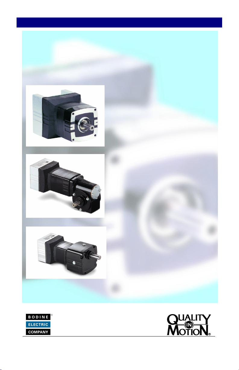
Instructions for Installation and Operation
M
TTM
N
T
E
G
R
A
IIN
T
E
G
R
moottoorr
A
m
BBrruusshhlleessss DDCC MMoottoorrss aanndd GGeeaarrmmoottoorrss wwiitthh
aaaa
aaaa
GGGG
GGGG
tttt
oooo
rrrr
ssss
tttt
oooo
rrrr
ssss
rrrr
mmmm
oooo
tttt
oooo
rrrr
oooo
rrrr
rrrr
mmmm
mmmm
ssss
tttt
oooo
rrrr
ssss
oooo
tttt
oooo
rrrr
oooo
tttt
oooo
rrrr
rrrr
eeee
eeee
mmmm
aaaa
aaaa
BBuuiilltt--IInn PPWWMM SSppeeeedd CCoonnttrrooll
DDDD
iiii
rrrr
eeee
cccc
tttt
DDDD
rrrr
iiii
vvvv
eeee
MMMM
DDDD
iiii
rrrr
eeee
cccc
tttt
DDDD
rrrr
iiii
vvvv
2222BB22BBEEBBLL//SSRR
2222BB44BBEEBBLL//SSRR
RRRR
iiii
gggg
hhhh
tttt
----
AAAA
nnnn
gggg
RRRR
iiii
gggg
hhhh
tttt
2222BB44BBEEBBLL//SSRR--33NN
PPPP
aaaa
rrrr
aaaa
PPPP
aaaa
rrrr
aaaa
2222BB22BBEEBBLL//SSRR--DD33
2222BB22BBEEBBLL//SSRR--DD44
2222BB33BBEEBBLL//SSRR--ZZ22
2222BB33BBEEBBLL//SSRR--ZZ33
2222BB22BBEEBBLL//SSRR--ZZ44
llll
----
AAAA
nnnn
gggg
llll
llll
eeee
llll
SSSS
llll
llll
eeee
llll
SSSS
oooo
eeee
MMMM
oooo
eeee
GGGG
eeee
llll
eeee
GGGG
eeee
hhhh
aaaa
ffff
tttt
hhhh
aaaa
ffff
tttt
ssss
ssss
www.bodine-electric.com Literature No. 074 01034.D (MW)
Page 2
QUICK REFERENCE
IMPORTANT
Read this manual completely and carefully. Pay special attention to
all warnings, cautions, and safety rules. Failure to follow the
instructions could produce safety hazards which could injure
personnel or damage the control, motor, or other equipment. If you
have any doubts about how to connect the control or motor, refer to
the detailed sections of this manual.
2
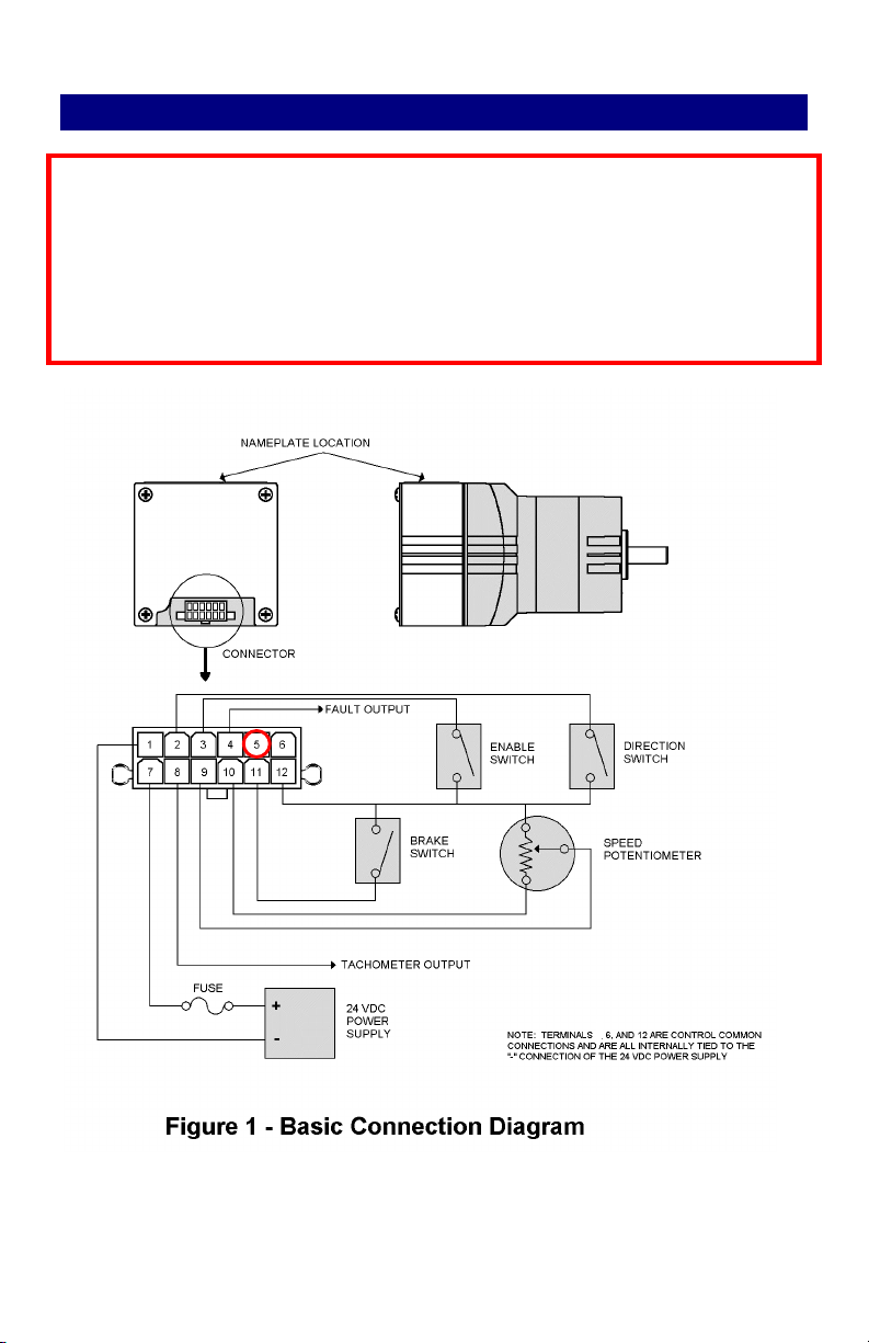
Pin No. 5 provides a Directi on Output Signal
Page 3

CONTENTS
This manual contains the basic information needed to install and operate a Bodine
INTEGRAmotorTM brushless DC motor & control system. This manual does not
profess to cover all details or variations in equipment, nor to provide for every
possible contingency associated with installation, operation, or maintenance. No
warranty of fitness for purpose is expressed or implied. Should further information
be desired or should particular problems arise which are not covered sufficiently for
the user’s purpose, the matter should be referred to the Bodine Electric Company.
PAGE
QUICK REFERENCE 2
PRODUCT SPECIFICATIONS 4
IMPORTANT SAFETY PRECAUTIONS 5
INSTALLATION 6
Step 1 – Examine Before Installation 6
Step 2 – Mount the Control 6
Step 3 – Make Electrical Connections 10
Step 3a – Make Cable 10
Step 3b – Connect Remote Control Devices to Cable 10
Step 3c – Ground the INTEGRAmotorTM 14
Step 3d – Connect Fuse 14
Step 3e – Connect DC Power Supply to Cable 14
Step 3f – Plug Cable into INTEGRAmotorTM 14
OPERATION 15
Step 4 – Check System Before Starting 15
Step 5 – Operate the INTEGRAmotorTM 15
TROUBLESHOOTING 19
DECLARATION OF CONFORMITY 22
WARRANTY 23
Copyright 2010. Bodine Electric Company. All Rights Reserved. Printed in U.S.A.
3
Page 4
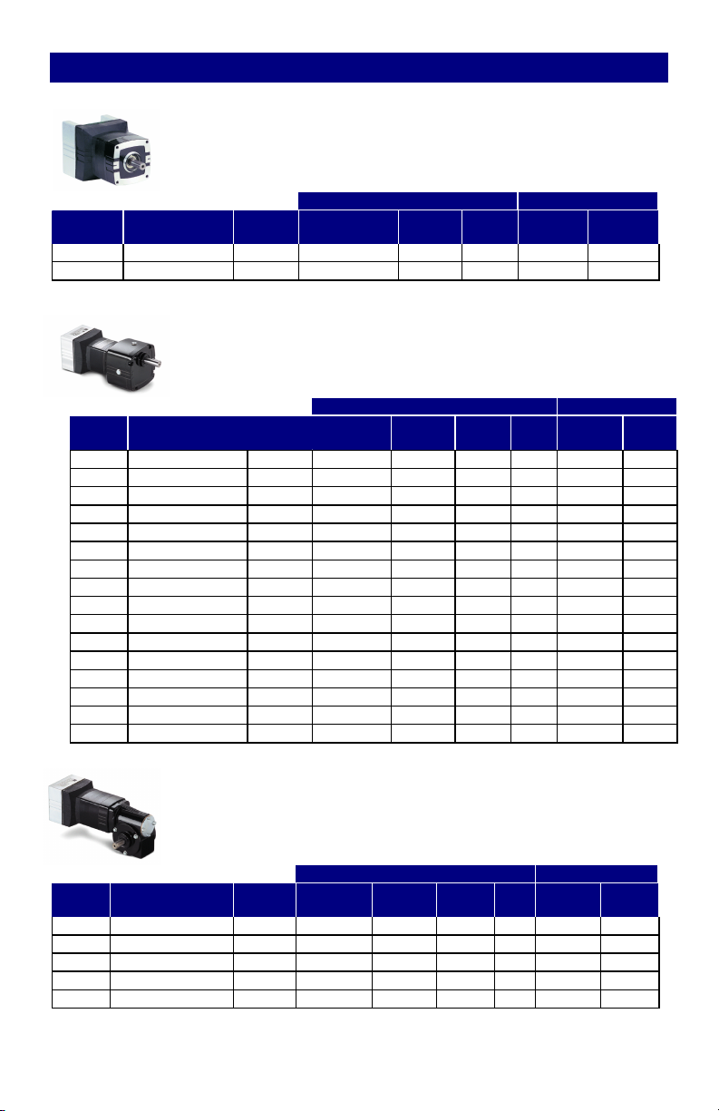
PRODUCT SPECIFICATIONS
-
MOTOR OUTPUT CONTROL INPUT
Model
Number
3802
3804
GEARMOTOR OUTPUT CONTROL INPUT
Model
No.
N3826
3827
N3828
3829
N3834
N3835
3836
N3837
3857
N3858
N3859
3860
N3861
N3862
3863
N3864
GEARMOTOR OUTPUT CONTROL INPUT
Model
No.
N3865
3866
N3867
3868
N3869
4
Ambient Rating: +25°C (+77°F)
Environmental Protection: IP-00
Frame Type Weight
22B2BEBL/SR 2.5 200 to 2500 25 1/16 24 4.0
22B4BEBL/SR 3.5 200 to 2500 50 1/8 24 6.0
Frame Type Weight
22B2BEBL/SR-D3 3.8 33 to 417 5.8 6:1 1/16 24 4.0
22B2BEBL/SR-D3 3.8 17 to 208 12 12:1 1/16 24 4.0
22B2BEBL/SR-D3 3.8 11 to 139 17 18:1 1/16 24 4.0
22B2BEBL/SR-D3 3.8 7 to 83 29 30:1 1/16 24 4.0
22B2BEBL/SR-D3 3.8 3 to 42 40 60:1 1/16 24 4.0
22B2BEBL/SR-D4 3.8 2 to 28 40 90:1 1/16 24 4.0
22B2BEBL/SR-D4 3.8 1 to 14 40 180:1 1/16 24 4.0
22B2BEBL/SR-D5 3.8 0.7 to 8 40 300:1 1/16 24 4.0
22B3BEBL/SR-Z2 5.3 33 to 417 10 6:1 1/11 24 5.0
22B3BEBL/SR-Z2 5.3 17 to 208 20 12:1 1/11 24 5.0
22B3BEBL/SR-Z2 5.3 11 to 139 31 18:1 1/11 24 5.0
22B3BEBL/SR-Z3 5.3 7 to 83 52 30:1 1/11 24 5.0
22B3BEBL/SR-Z3 5.3 3 to 42 95 60:1 1/11 24 5.0
22B2BEBL/SR-Z4 4.8 2 to 28 97 90:1 1/16 24 4.0
22B2BEBL/SR-Z4 4.8 1 to 14 100 180:1 1/16 24 4.0
22B2BEBL/SR-Z4 4.8 0.7 to 8 120 300:1 1/16 24 4.0
Frame Type Weight
22B4BEBL/SR-3N 5.4 3 to 42 37 60:1 1/8 24 6.0
22B4BEBL/SR-3N 5.4 5 to 62 37 40:1 1/8 24 6.0
22B4BEBL/SR-3N 5.4 10 to 125 35 20:1 1/8 24 6.0
22B4BEBL/SR-3N 5.4 20 to 250 22 10:1 1/8 24 6.0
22B4BEBL/SR-3N 5.4 40 to 500 11 5:1 1/8 24 6.0
(lbs)
(lbs)
(lbs)
SPECIFICATIONS OF DIRECT DRIVE MODELS
Speed
(rpm)
Torque
(oz-in)
HP Volts
(VDC)
SPECIFICATIONS OF PARALLEL SHAFT MODELS
Speed
(rpm)
Torque (lb
in)
Gear
Ratio
HP Volts
(VDC)
SPECIFICATIONS OF RIGHT ANGLE MODELS
Speed
(rpm)
Torque
(lb-in)
Gear
Ratio
HP Volts
(VDC)
Cont.
Amps
Cont.
Amps
Cont.
Amps
Page 5
IMPORTANT SAFETY PRECAUTIONS
“The use of electric motors and generators, like that of all other utilization of
concentrated power, is potentially hazardous. The degree of hazard can be
greatly reduced by proper design, selection, installation, and use, but
hazards cannot be completely eliminated. The reduction of hazard is the
joint responsibility of the user, the manufacturer of the driven or driving
equipment, and the manufacturer of the motor or generator.”*
Please read through this operations manual in detail and observe those
paragraphs with the safety alert symbol.
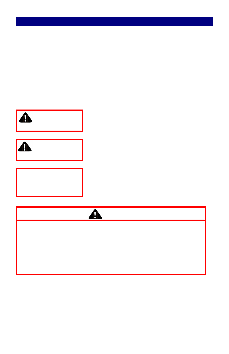
WARNING
CAUTION
CAUTION
WARNING indicates a potentially hazardous
situation which, if not avoided, could result in
death or serious injury.
CAUTION indicates a potentially hazardous
situation which, if not avoided, may result in
minor or moderate injury.
CAUTION used without the safety alert
symbol indicates a potentially hazardous
situation which, if not avoided, may result in
property damage.
WARNING
Do not touch printed circuit board (PCB) right after
turning off power.
Do not attempt to wire circuitry while power is on.
Do not attempt to examine components and signals on
the PCB while the INTEGRAMOTORTM is operating.
Do not attempt to disassemble or modify internal
components or wiring of the INTEGRAMOTORTM.
* Standards Publication No. ANSI/NEMA MG-2, “Safety Standard for Construction and Guide for
Selection, Installation and Use of Electric Motors and Generators.” (Ref.: www.nema.org).
5
Page 6
INSTALLATION
This product should only be installed by a qualified person familiar
with its operation and associated hazards. The National Electrical
Code (NEC), local electrical and safety codes, and when
applicable, the Occupational Safety and Health Act (OSHA) should
be observed to reduce hazards to personnel and property.
Step 1. Examine before installation
CAUTION
The PCB of the INTEGRAmotor
TM
is vulnerable to static
electrical charges. For this reason, the
INTEGRAMOTORTM is packaged in an anti-static bag.
Remove the INTEGRAmotorTM from the bag only in an
area protected from electrostatic discharges (ESD).
Check the items you received against the model numbers specified on your
purchase order. The serial number is printed on an adhesive label on the top side
of the control housing. The first four digits in the serial number correspond to the
model number. Carefully examine the product for shipping damage. Parts errors
should be reported to Bodine. Shipping damage claims should be made to the
freight carrier.
CAUTION
Do not connect the INTEGRAmotorTM to the power supply if
there is any sign of shipping damage.
Step 2. Mount the INTEGRAMOTORTM
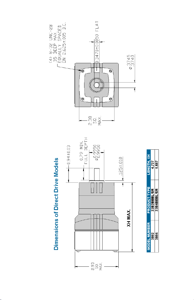
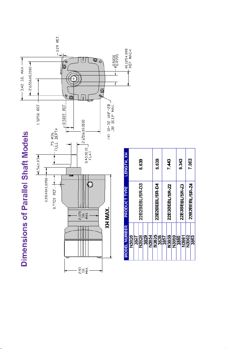
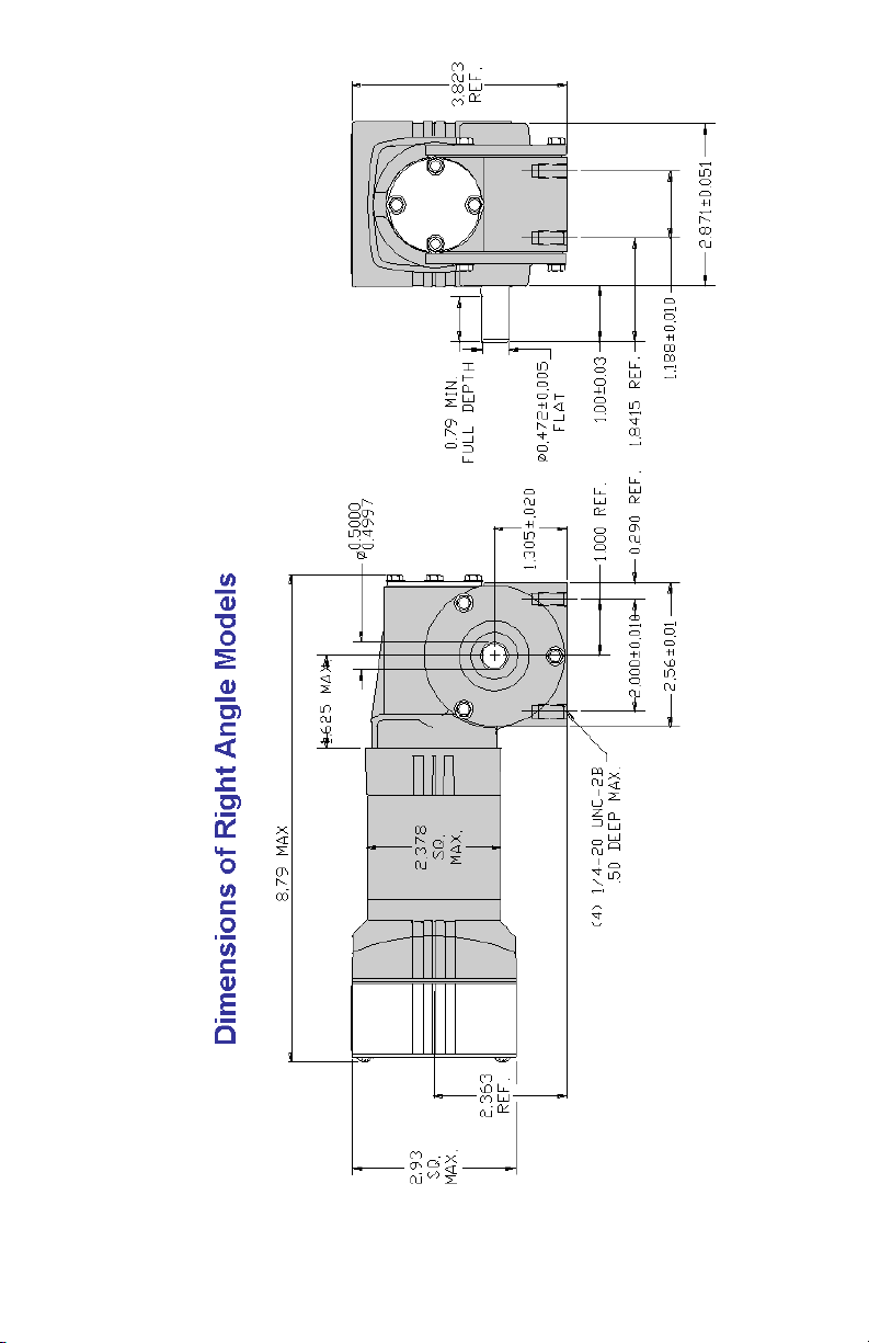
Install the INTEGRAMOTORTM onto a firm base by inserting screws into the four
threaded holes in the mounting surface. See the following dimension drawings
for location of mounting holes.
INTEGRAmotorsTM without gearing can be mounted in any position. Our
standard gearmotors are designed for universal horizontal mounting orientation.
Consult the factory for suggestions if the gearmotors are mounted vertically.
Surrounding air temperature can be from 0O C to +25O C (rated ambient temp.).
Prevent liquid from dripping onto the INTEGRAmotorTM.
Avoid environments that are humid or that have corrosive gas.
Avoid locations near radioactive matter, flammable material, or by equipment
that emits electromagnetic interference (EMI).
Avoid mounting the INTEGRAmotorTM to a surface that experiences excessive
vibration.
6
Page 7
7
Page 8
8
Page 9
9
Page 10
Step 3 – Electrical Connections
Step 3a – Make a Cable
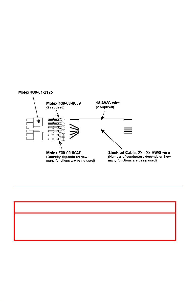
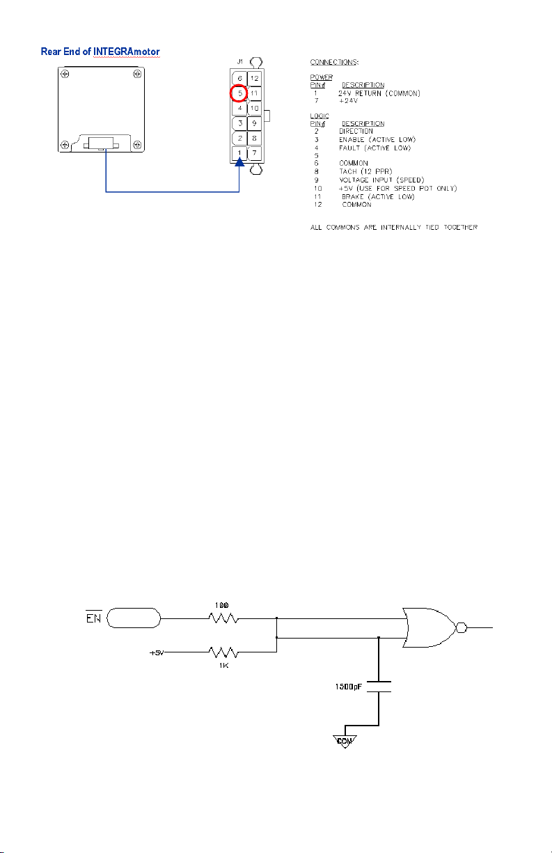
The INTEGRAmotorTM has a single plug-in header for all electrical connections. Fig.
3 shows the location of this header. The mating connector is supplied in the
packaging of the INTEGRAmotorTM, but the user must attach wires to that
connector. It is recommended that the wires used to connect the INTEGRAmotorTM
to the 24V power supply be less than 12 feet long. Although this restriction doesn’t
apply to the wires for the logic connections, it is recommended that shielded cable
be used if the logic wires are longer than 5 feet. It is also recommended that the
power wires be separate from the shielded cable used for logic connections. If it is
desired for the power wires to be shielded, then a separate shielded cable should be
used for the power and logic connections.
Figure 2 - Construction of Mating Cable
Step 3b – Connect Remote Control Devices to Cable
CAUTION
The printed circuit board (PCB) of the
INTEGRAMOTORTM is vulnerable to electrostatic
discharges (ESD). Do not contact the PCB unless
precautions are followed to prevent ESD.
10
Page 11
DIRECTION OUTPUT (see Page 14)
Figure 3 - Functions of Connector Terminals
The INTEGRAmotorTM can be connected for manual operation with switches and a
speed potentiometer, as shown in Fig. 1, or it can be connected for remote
operation from a programmable logic controller (PLC) or other control device.
DIRECTION INPUT (Terminal 2) - This input is normally high, pulled up to the
internal 5V reference. If left high, rotation of the motor shaft will be counterclockwise (CCW) looking at the motor shaft (clockwise for parallel shaft
gearmotors having an odd number of gearing stages). To reverse motor
rotation, pull the input low. It can be pulled low by either connecting it to a
switch to one of the common terminals (Terminals 6 and 12), as shown in Fig.
1, or by connecting it to an open collector output from a PLC or other control
device. Note that it is not recommended to change direction while the
INTEGRAMOTORTM is running. It should be brought to a stop first, and then
reversed. A schematic diagram is shown in Fig. 4.
ENABLE INPUT (Terminal 3) – This input is normally high, pulled up to the
internal 5V reference, and must be pulled low to allow operation of the
INTEGRAMOTORTM. It can be pulled low by either connecting it to a switch to
one of the common terminals (Terminals 6 and 12), as shown in Fig. 1, or by
connecting it to an open collector output from a PLC or other control device. A
schematic diagram for this input is shown in Fig. 4.
Figure 4 - Schematic diagram for Enable, Direction, and Brake Inputs
11
Page 12
FAULT OUTPUT (Terminal 4) – The fault output is an open drain output
connected directly to the main controller chip. It can be connected to a
maximum of 12 VDC with a 10.0k ohm, 1/8 Watt resistor. The fault output will
switch low to indicate at least one of the following conditions: (1) the controller
is disabled because the enable input is high, (2) a shutdown has occurred
because there is less than 20 VDC applied to the power input of the
INTEGRAMOTORTM (undervoltage lockout), (3) a shutdown has occurred
because of an invalid combination of commutation sensor signals, or (4) a
shutdown has occurred because of an overcurrent from the controller chip (not
the motor windings).
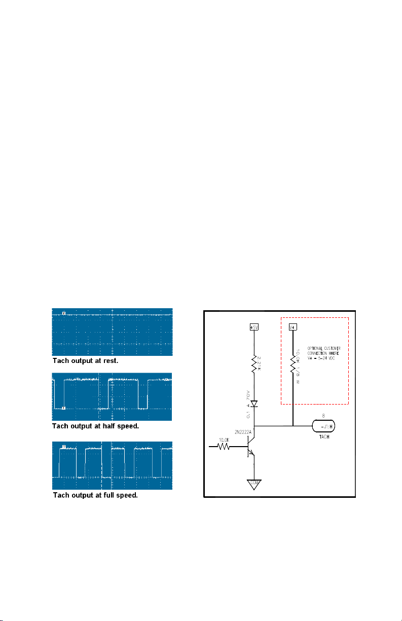
TACHOMETER OUTPUT (Terminal 8) – This output is normally high, pulled up to
the internal 5V reference. It can be connected to an external device to monitor
the speed of the INTEGRAMOTORTM. The output is a negative pulse that goes
from high to low, as seen in Fig. 5. Note that this is not the same as the square
wave output of a typical encoder. The active portion of the signal, that part at
common, has a fixed width of 0.8 msec, while the high portion of the signal will
change width based on the speed of the INTEGRAMOTORTM. Twelve pulses
are produced for each revolution of the motor shaft (not the same as the
driveshaft on a geared INTEGRAMOTORTM). To calculate the resolution of the
tach output with respect to the driveshaft of a geared INTEGRAMOTORTM,
multiply the gear ratio by 12. No external pull-up resistor is necessary if the
remote control device operates with 5V supply. The tach output will work with
supply voltages up to 24 VDC with a user-supplied 10k pull-up resistor, per
Figure 6.
Figure 5 - Waveform of Tach Output Figure 6 – Schematic diagram of
Tach Output
12
Page 13
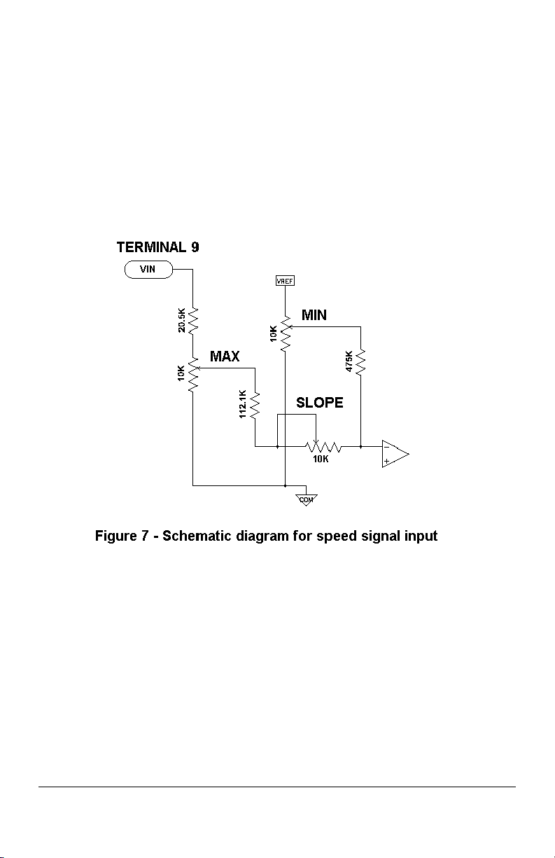
SPEED SIGNAL INPUT (Terminal 9) – Connect a remote analog voltage signal to
terminal 9. The drive will accept a 0 – 5 VDC signal. This signal does not have
to be isolated since the 24 VDC power supply already isolates the
INTEGRAMOTORTM from the AC line. Alternatively, a speed potentiometer can
be connected to the drive as shown in Fig. 1 with the wiper connected to
terminal 9 and the two end terminals of the speed pot connected to terminals 10
and 12. Since the speed pot acts as a voltage divider, the exact value is not
critical, but a 10k ohm potentiometer is recommended. A schematic diagram
for the speed signal input is shown in Fig. 7. A typical response curve, showing
the relationship between the rotor speed of the INTEGRAMOTORTM to the
voltage of the speed signal, is shown in Fig. 11.
BRAKE INPUT (Terminal 11) - This input is normally high, pulled up to the internal
5V reference. To dynamically brake the INTEGRAMOTORTM to a stop, pull the
input low. It can be pulled low by either connecting it to a switch to one of the
common terminals (Terminals 6 and 12), as shown in Fig. 1, or by connecting it
to an open collector output from a PLC or other control device. Note that this
function is not the same as a holding brake. It brings the INTEGRAMOTORTM
to a quick stop, but will not hold it in place. The stopping time is a function of
many variables and must be determined independently for each application.
Some of the variables include the size of the INTEGRAMOTORTM, the gear
ratio, the load inertia, and friction. Typical stopping performance is shown
graphically in Fig. 8, with time divisions of 10 msec. A schematic diagram for
the brake input is shown in Fig. 4.
13
Page 14

DIRECTION OUTPUT (Terminal 5, page 11) – The direction output will be at +5V while
the motor is turning CCW (looking at the motor shaft), and 0V when the motor is
turning CW. This output will change state after the motor has been running in the
new direction for at least 1/2 revolution. For gearmotors, the direction output will
change after the motor has run 1/(2*n) revolutions where n is the gear ratio. If the
number of gear stages is odd, the direction output will be inverted as compared to
motors with an even number of stages or no gearing. For compatibility with the new
versions Bodine recommends existing users update their designs to leave pin 5
unterminated or connected to a logic input.
________________________________________________
Step 3c – Ground the INTEGRAMOTOR
TM
There is no ground wire or ground terminal on the INTEGRAmotorTM. It must be
grounded through the mounting points or a user-supplied ground wire must be
connected to the frame.
Step 3d – Connect Fuse
The INTEGRAMOTORTM must be protected by a user-supplied fuse. In a system
with multiple INTEGRAMOTORsTM, each one must be protected separately. Make
sure the fuse is connected in series with the +24 volt lead of the power supply. See
Fig. 1. The rating of the fuse is dependent on the amount of input current drawn by
the control when the motor is operated at full load. Determine the fuse rating by
multiplying the nameplate current rating of the INTEGRAMOTORTM by 1.25 and
round the number up to the closest commercially available fuse rating. Note that
maximum current is drawn by the INTEGRAMOTORTM in a condition where the
INTEGRAMOTORTM is set for full speed and is overloaded, but not enough to cause
a stall. Because of the nature of the PWM type drive, the current is actually lower
when the INTEGRAMOTORTM is stalled.
Step 3e – Connect DC Power Supply to Cable
CAUTION
Use a power supply that is regulated to a voltage
between 20 VDC and 28 VDC, and that has a current
rating that matches the INTEGRAMOTORTM rating.
Step 3f – Plug Cable into INTEGRAmotor
14
TM
Page 15
OPERATION
Step 4 – Check System Before Starting
WARNING
Recheck all connections.
Do not remove the cover over the electronics when the
power is ON to avoid personnel injury caused by
electrical shock.
Do not attempt to install or remove the electrical
connector when the power supply is turned on. Do not
attempt to wire circuitry while power is on.
CAUTION
Check that motor is securely mounted.
Test INTEGRAMOTOR
Check all rotating members. Be sure keys, pulleys, etc.
TM
unloaded first.
are securely fastened and safety guards are in place.
Check for proper mounting and alignment of products,
and verify safe loading on shafts and gears.
Step 5 – Operate the INTEGRAMOTORTM
Assuming the INTEGRAMOTORTM has been connected as in Fig. 1, use the
following procedure to start the motor, adjust the speed, stop the motor, and reverse
direction.
1) START AND ADJUST SPEED
a) Set the ENABLE switch high, the SPEED POT to zero, and the BRAKE
input high.
b) Turn the 24 VDC power supply ON.
c) Switch the ENABLE input low.
d) Turn the SPEED POT to start rotation and to increase motor speed.
2) COAST TO STOP AND RESTART
a) Switch the ENABLE input high to cut power to the INTEGRAMOTORTM and
bring it to a slow stop.
b) Turn SPEED POT to zero.
c) Switch ENABLE input low.
d) Turn SPEED POT to start rotation and increase speed.
15
Page 16
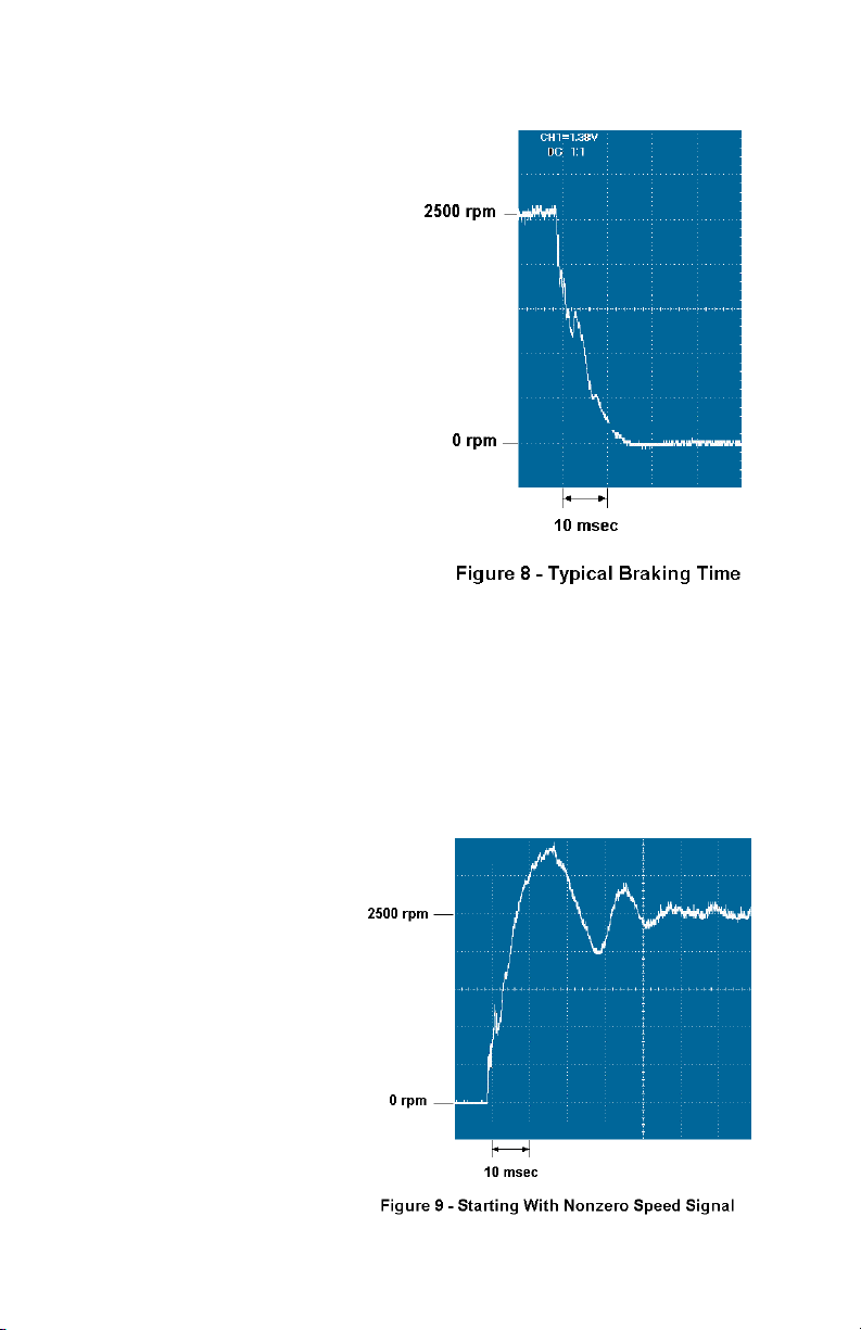
3) BRAKE TO STOP AND RESTART
a) Switch the BRAKE input low
to dynamically brake the
INTEGRAMOTORTM to a
quick stop. Typical
stopping time is shown in
Fig. 8.
b) Turn SPEED POT to zero.
c) Switch BRAKE input high.
d) Turn SPEED POT to start
rotation and increase
speed.
4) STOP, CHANGE DIRECTION,
AND RESTART
a) Stop the
INTEGRAMOTORTM using
either the ENABLE input or
the BRAKE input, as
described above.
b) Turn the SPEED POT to
zero.
c) Switch the DIRECTION
input to change the
INTEGRAMOTORTM’s direction of shaft rotation. Note the DIRECTION
input should not be changed while the INTEGRAMOTORTM is running.
d) Restart the INTEGRAMOTORTM as described above.
5) STOP AND RESTART WITHOUT ZEROING SPEED SIGNAL
a) Stop the INTEGRAMOTORTM using either the ENABLE input or the BRAKE
input, as described above.
b) Leaving the SPEED POT set at some speed higher than zero, restart the
INTEGRAMOTORTM.
Note that there is some
overshoot of the set
speed during the
acceleration, as shown
in Fig. 9. This is
because the control in
the INTEGRAmotor
TM
does not have a
ramping circuit. If
overshoot is not
acceptable in the
application, then zero
the speed signal
before restarting, as
described above or
refer to Figure 14 on
page 22.
16
Page 17
6) INTERNAL ADJUSTMENTS
CAUTION
The printed circuit board (PCB) of the
INTEGRAMOTORTM is vulnerable to electrostatic
discharges (ESD). Do not contact the PCB unless
precautions are followed to prevent ESD.
Most applications should not require the user to remove the metal plate that
covers the control PCB. However, certain situations (see
“TROUBLESHOOTING” section) may require adjustment of the trim
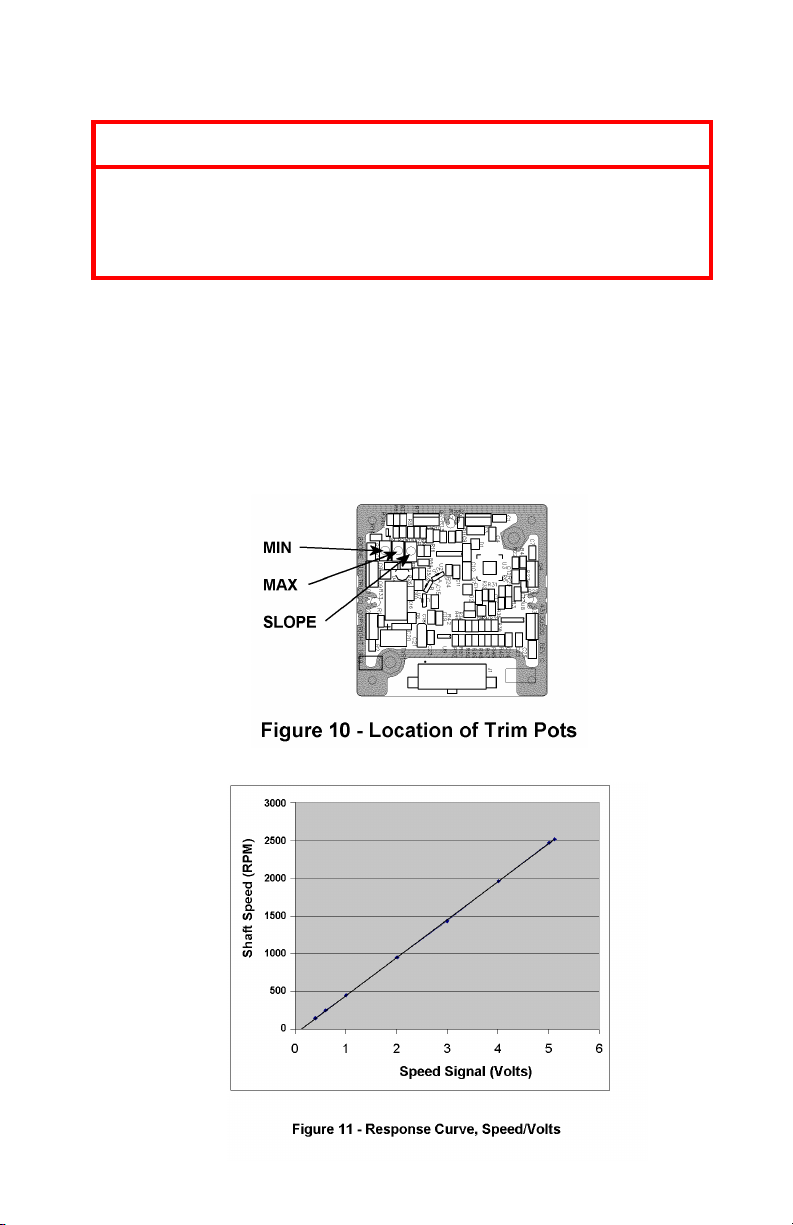
potentiometers on the PCB. The trim pots affect the response of the
INTEGRAMOTORTM to the speed signal at Terminal 9. They are factory
calibrated so that the INTEGRAMOTORTM will not run when the speed signal is
0V (with a little dead band to account for component tolerances) and so it will
run at 2500 rpm (before any gear reduction) when the speed signal is 5V. See
Fig. 10 for location of the trim pots and Fig. 11 for the response curve.
17
Page 18
7) IF PROBLEMS OCCUR
If the INTEGRAMOTORTM does not start promptly and run smoothly, refer to the
“TROUBLESHOOTING” section. Make sure the INTEGRAMOTORTM isn’t just
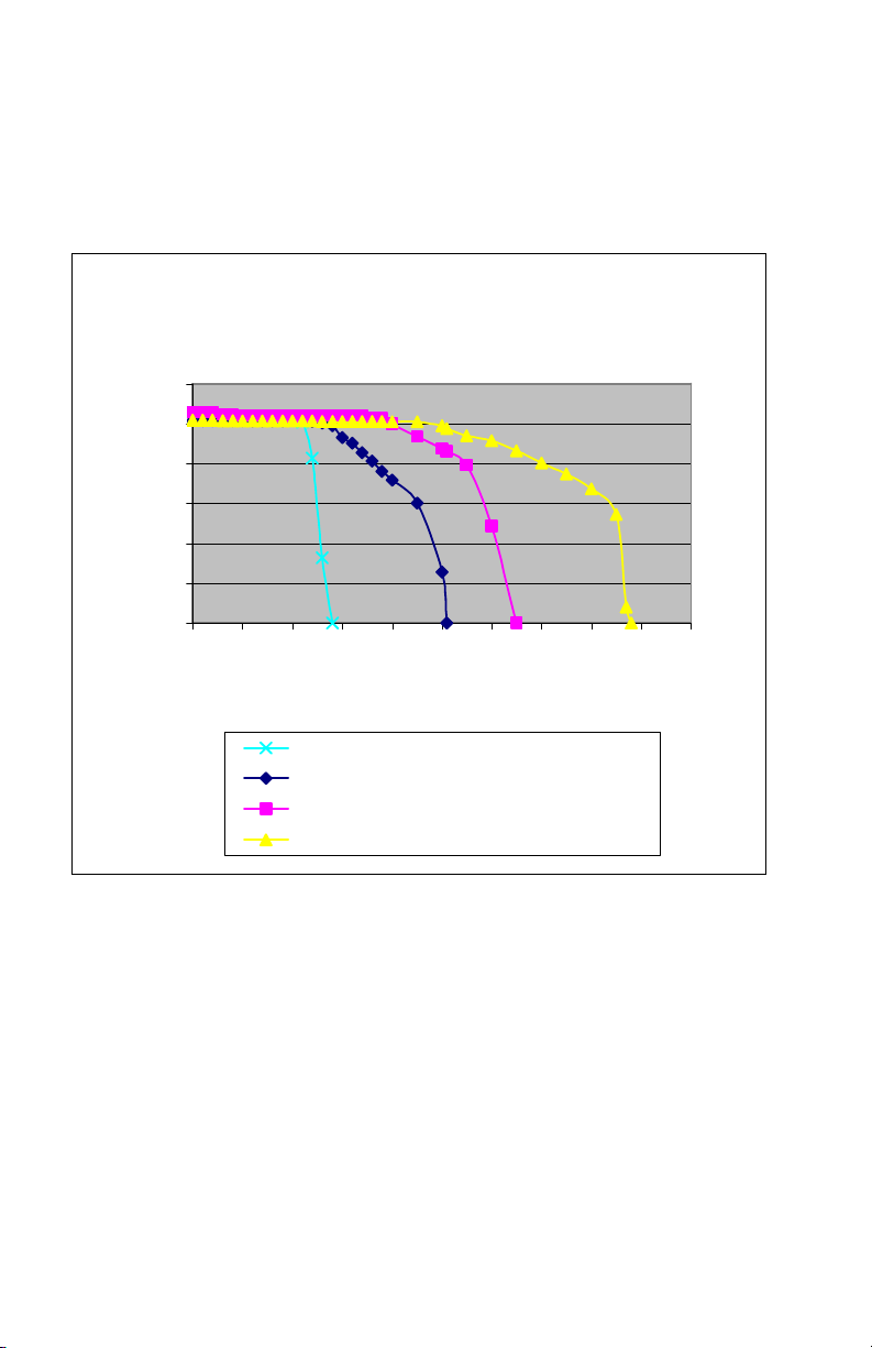
overloaded. Fig. 12 shows the stall point for each size INTEGRAMOTORTM
(without gearing).
SPEED/TORQUE CURVES
(motors without gearing)
3000
2500
2000
1500
1000
SPEED, RPM
500
0
0 10 20 30 40 50 60 70 80 90 100
TORQUE, OZ-IN
Figure 12 – Speed/Torque Curves showing effect of current limit
18
Type 22B2 (with high gear ratios)
Type 22B2 (with low gear ratios)
Type 22B3
Type 22B4
Page 19

TROUBLESHOOTING
WARNING
Do not remove the cover over the electronics when the
power is ON to avoid personnel injury caused by
electrical shock.
Do not attempt to install or remove the electrical
connector when the power supply is turned on. Do not
attempt to wire circuitry while power is on.
If you encounter a problem, read all instructions and double-check the wiring. Even
if the INTEGRAMOTORTM itself is definitely defective, it may be that another
defective component in the system caused it to fail, in which case replacing the
INTEGRAMOTORTM alone and not tending to the root cause of the failure may result
in another damaged product. Figure 13 may assist in troubleshooting foreseeable
problems which may occur during installation and operation.
If problems persist, contact your source of purchase or a Bodine Authorized Service
Center and describe the problem in detail. Do not disassemble the product unless
authorized by Bodine Electric Company. Performing unauthorized repairs will void
the Warranty.
GENERAL EVALUATION – Knowing the circumstances under which the problem
occurred can help to identify the root cause of the problem. The following are two
questions you should ask yourself before tearing everything apart:
Has the system ever operated properly? If the system was just installed and
hasn’t worked right from the beginning, then it is very likely that something wasn’t
done correctly in the installation. Focus on incorrect wiring or incorrect
programming of remote devices. On the other hand, if the system has been working
for an extended period of time and just recently stopped working, then this would
indicate that the system was initially installed properly but has somehow changed.
Focus instead on failed components or deteriorated wiring.
Is the problem continuous or intermittent? If the problem always occurs and
never goes away, then it would indicate something inherently wrong in the
connections or a defective component. On the other hand, if the system operates
properly most of the time and only occasionally does something wrong, then this
might indicate loose connections or electrical noise interference.
19
Page 20

ISOLATE THE PROBLEM – If there are no obvious indications that the
Check that remote device, if used, is giving a
INTEGRAmotorTM has failed (i.e. burn marks or smoke), then don’t assume that it is
the defective component.
Disconnect external devices – Disconnect all external devices to make sure
they are not causing the problem. Leave only the power supply connected, to
terminals 1 and 7, but make sure first that power is actually getting to the
INTEGRAMOTORTM. Hard wire the ENABLE by connecting a short loop of
wire between terminals 3 and 12. Hard wire the INTEGRAMOTORTM for full
speed operation by connecting a short loop of wire between terminals 9 and
10. Connect nothing else to the INTEGRAMOTORTM. Now turn on the power
and observe if the INTEGRAMOTORTM runs at full speed. If it does, then
proceed to the next step. If it doesn’t, then the INTEGRAMOTORTM probably
needs service.
Reconnect external devices one at a time - Assuming the system worked
okay with just the INTEGRAMOTORTM and power connected, reconnect and
test each external device separately to identify which one is causing the
problem. Remember that the problem may not be the device itself, but the
wiring connecting it to the INTEGRAMOTORTM.
FIGURE 13 - General problem evaluation method
SYMPTOM PROBABLE CAUSE CORRECTIVE ACTION
Does not operate Incorrect power supply wiring Check that power source is switched on.
Incorrectly sized power supply Replace power supply with unit having
Blown fuse Replace fuse.
ENABLE input is high Correct any loose or open connection to
No speed signal Check if speed potentiometer, if used, is
BRAKE input is low Correct any loose or bare wires that might
INTEGRAMOTORTM is
INTEGRAMOTORTM is damaged Contact Bodine or an Authorized Service
Operates, but in
wrong direction
overloaded
Direction input set wrong Switch DIRECTION input.
Check connections. Look for shorts and
repair as required.
sufficient voltage and current capacity to
provide 24V under full load
ENABLE input
Switch ENABLE input low if it is high.
working properly.
Check wiring for speed potentiometer or
remote analog input signal
signal to the INTEGRAMOTORTM.
be shorting BRAKE input to ground.
Switch BRAKE input high if it is low.
Reduce load
Replace INTEGRAMOTOR
model
Center for assistance.
TM
with stronger
20
Page 21

FIGURE 13 - General problem evaluation method (continued)
SYMPTOM PROBABLE CAUSE CORRECTIVE ACTION
Operates, but speed
can’t be adjusted
Incorrect wiring of speed
Operates, but won’t
come up to speed
MAX trim pot set too low Adjust MAX trim pot
Incorrectly sized power supply Replace power supply with unit having
Operates, but with
abnormal speed
variations
Operates, but won’t
stop with zero speed
signal
Incorrect wiring of speed
MIN trim pot set too high Adjust MIN trim pot
Operates, but surges
when started
Operates, but won’t
maintain speed under
load
INTEGRAMOTORTM is
Defective speed potentiometer Replace speed potentiometer
potentiometer or remote speed
Check and correct connections
signal
INTEGRAMOTORTM is
overloaded
Reduce load
Replace INTEGRAMOTOR
model
sufficient voltage and current capacity to
provide 24V under full load
Speed setting too low Increase speed
Replace INTEGRAMOTOR
having higher gear ratio
Defective speed potentiometer Replace speed potentiometer
potentiometer or remote speed
Check and correct connections
signal
Starting with speed signal set
higher than zero
Set speed pot or remote signal to zero
before starting
Add external circuitry to provide a ramping
function (consult Bodine)
Incorrectly sized power supply Replace power supply with unit having
sufficient voltage and current capacity to
provide 24V under full load
overloaded
Reduce load
Replace INTEGRAMOTOR
model
TM
with stronger
TM
with model
TM
with stronger
21
Page 22
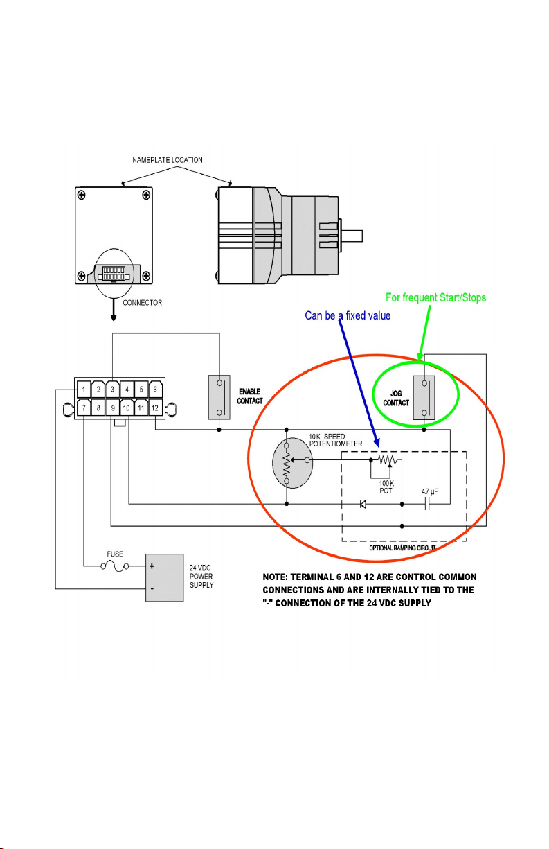
FIGURE 14 – External “ramping circuit” for smooth 22B/SR acceleration (Refer to 5b on page 16)
22
Page 23

DECLARATION OF CONFORMITY
We, the Bodine Electric Company, 201 Northfield Road, Northfield, Illinois, U.S.A.,
phone (773) 478-3515, fax (773) 478-3232, declare under our sole responsibility
that the following products:
INTEGRAmotoTM series Brushless DC Motors and Gearmotors with Integral Electronic
Speed Controls. Product types:
22B2BEBL/SR (model 3802);
22B4BEBL/SR (model 3804);
22B2BEBL/SR-D3 (models N3826, 3827, N3828, 3829, and N3834);
22B2BEBL/SR-D4 (models N3835 and 3836);
22B3BEBL/SR-Z2 (models 3857, N3858, and N3859);
22B3BEBL/SR-Z3 (models 3860 and N3861);
22B2BEBL/SR-Z4 (models N3862 and 3863);
22B4BEBL/SR-3N (models N3865, 3866, N3867, 3868, and N3869).
Are in conformity with the following standards when installed in accordance with the
supplied installation instructions:
EN 50081-1 / 01.92 Generic Emissions Standard for Heavy Industrial Environment
EN 50081-2 / 09.98 Generic Emissions Standard for Residential, Commercial, and Light
Industrial Environments
EN 55022 / 09.98 Conducted and Radiated Emissions for Information Technology
Equipment (ITE), Class A & B
EN 55011 / 03.91 Conducted and Radiated Emissions for Industrial, Scientific and
Medical Equipment (ISM), Class A & B
EN 50082-1 / 08.97 Generic Immunity Standard for Residential, Commercial, and Light
Industrial Environments
EN 61000-6-2 / 09.99 Generic Immunity Standard for Heavy Industrial Environments
EN 61000-4-2 / 03.95 Immunity to Electrostatic Discharge
EN 61000-4-3 / 09.96 Immunity to Radiated Electromagnetic Field
EN 61000-4-4 / 03.95 Immunity to Electrical Fast Transients/Burst
EN 61000-4-5 / 03.95 Immunity to Surge/Transient Overvoltages
EN 61000-4-6 / 07.96 Immunity to Conducted Electromagnetic Disturbance
And therefore satisfy the conditions for the following EC directives:
EMC Directive (89/336/EEC, amended by 92/31/EEC and 93/68/EEC)
Signature:
Full Name: Terrence J. Auchstetter
Position: Product Manager
Date: May 18, 2001
23
Page 24

BODINE LIMITED WARRANTY
The Bodine Electric Company warrants all products it manufactures to be free of
defects in workmanship and materials when used under Normal Operating
Conditions and when applied in accordance with nameplate specifications.
When Bodine motors and gearmotors have been purchased with and used only with
appropriately applied Bodine controls, this warranty shall be in effect for a period of
twenty-four months from date of purchase or thirty months from date of
manufacture, whichever comes first. Bodine motors and gearmotors used with nonBodine controls and Bodine controls used with non-Bodine motors and gearmotors
are covered by standard twelve-month warranty period.
The Bodine Electric Company will repair or replace at its option, any of its products,
which has been found to be defective and is within the warranty period, provided
that the product is shipped freight prepaid, with previous authorization, to Bodine
Electric, or to the nearest Bodine Authorized Service Center. At its option, all return
shipments are F.O.B. Bodine’s plant or Authorized Service Center. Bodine is not
responsible for removal, installation, or any other incidental expenses incurred in
shipping the products to or from Bodine.
This warranty is in lieu of any other expressed or implied warranty - including (but
not limited to) any implied warranties of merchantability and/or fitness for a particular
use or purpose.
Bodine’s liability under this warranty shall be solely limited to repair or replacement
of the Bodine product within the warranty period and Bodine shall not be liable,
under any circumstances, for any consequential, incidental or indirect damages or
expenses associated with the warranted products.
Commutator and/or brush wear and its associated effects are normal occurrence
and are not covered by this warranty unless otherwise agreed to by Bodine in
writing.
Proof of purchase of motor or gearmotor and matching control as a system must be
provided with any claim.
Bodine Electric Company
201 Northfield Road
Northfield, Illinois 60093 U.S.A.
TEL: (773) 478-3515
FAX: (773) 478-3232
www.bodine-electric.com
24
 Loading...