

Bodart & Gonay PHENIX Green, Phenix Green 75, Phenix Green 120, Phenix Green 80, Phenix Green 95 Installation And User Manual

PHENIX Green US
PHENIX Green
USA / Canada
Installation and User Manual
Version 12-40
Phenix Green 75
Phenix Green 85
Phenix Green 95
Phenix Green 120

PHENIX Green US
Version 12-40
Table of Contents
1. GENERAL REMARKS .................................................................................1
1.1. CONTACT INFORMATION
...................................................................1
1.2. WARRANTY
..........................................................................................2
1.3. IMPORTANT SAFETY INFORMATION
.................................................3
1.4. PRODUCT FEATURES.........................................................................3
2. USING THE APPLIANCE .............................................................................4
2.1. FUEL
.....................................................................................................4
2.2. FIRST FIRE
...........................................................................................5
2.3. REQUIRED FOR EVERY FIRE
............................................................5
2.4. DESCRIPTION
......................................................................................6
2.5. OPENING-CLOSING
............................................................................7
2.6. USING THE FIREPLACE
......................................................................7
2.7. SETTING AND USING THE BAFFLES
...............................................10
3. MAINTENANCE .........................................................................................12
3.1. ONGOING MAINTENANCE
................................................................12
3.2. YEARLY MAINTENANCE
...................................................................14
4. INSTALLATION ..........................................................................................15
4.1. ADAPTER KIT FOR US AND CANADIAN MARKETS
........................15
4.2. CHIMNEY FLUE
.................................................................................15
4.3. BUILT-IN CHASE (FRAMING)
............................................................17
4.4. REQUIRED AIR FLOW
.......................................................................21
4.5. INSTALL PROCEDURES
....................................................................25
4.6. FIREBRICK AND DECORATIVE METAL
............................................26
4.7. FRAME (optional)
................................................................................27
5. ANNEX .......................................................................................................28
5.1. TECHNICAL DRAWINGS (Measures in mm [inches])
........................29
5.2. CERTIFICATIONS & PERFORMANCES
............................................34
5.3. TROUBLESHOOTING
........................................................................35
5.4. SPARE PARTS
....................................................................................36
5.5. US ADAPTER KIT
...............................................................................39
Table des matières
1. REMARQUES GÉNÉRALES .......................................................................1
1.1. CONTACTS
...........................................................................................1
1.2. GARANTIE
............................................................................................2
1.3. IMPORTANT: SÉCURITÉ......................................................................3
1.4. CARACTÉRISTIQUES DU PRODUIT
..................................................3
2. UTILISATION DU FOYER ............................................................................4
2.1. COMBUSTIBLE
....................................................................................4
2.2. LE PREMIER FEU
................................................................................5
2.3. IMPERATIF A CHAQUE FEU
...............................................................5
2.4. DESCRIPTION DE L’APPAREIL
...........................................................6
2.5. OUVERTURE-FERMETURE
...............................................................7
2.6. CONDUITE DU FEU
.............................................................................7
2.7. REGLAGE ET MANIPULATION DES CHICANES..............................10
3. ENTRETIEN ..............................................................................................12
3.1. ENTRETIEN COURANT
.....................................................................12
3.2. ENTRETIEN ANNUEL.........................................................................14
4. INSTALLATION ..........................................................................................15
4.1. ADAPTATION POUR LES MARCHES US ET CANADIENS
..............15
4.2. CONDUIT DE FUMEES
......................................................................15
4.3. ENCASTREMENT/ HABILLAGE
........................................................17
4.4. FLUX D’AIR NECESSAIRES
..............................................................21
4.5. MISE EN PLACE
.................................................................................25
4.6. BRIQUES OU DECO METAL
..............................................................26
4.7. CADRE (option)
..................................................................................27
5. ANNEXES ..................................................................................................28
5.1. SCHÉMAS TECHNIQUES (Cotes en mm [pouces])
..........................29
5.2. CERTIFICATIONS ET PERFORMANCES
..........................................34
5.3. DYSFONCTIONNEMENTS
................................................................35
5.4. PIÈCES DE RECHANGE
....................................................................36
5.5. KIT ADAPTATION US
.........................................................................39
1
PHENIX Green US
Version 12-40
1. GENERAL REMARKS
1.1.
ContaCt information
Manufacturer Importer Testing agency
Bodart & Gonay S.A.
Rue de Lambinon 3
4920 Harzé
Belgium
Tel: +32.4.239.93.93
Fax:+32.4.239.93.98
Email: info@bgres.com
Web: www.bgres.com
Wittus Inc.
40 Westchester Avenue
Pound Ridge NY 10576
USA
Tel:+1.914.764.5679
Fax:+1.914.764.0465
E-mail: info@wittus.com
Web: www.wittus.com
Guardian Fire Testing Labs, Inc.
15 Wenonah Terr.
Tonawanda NY 14150
USA
Tel:+1.716.835.6880
Fax:+1.716.835.5682
Email: gftli@earthlink.net
Web: www.retesting.com
Dear Customer,
Congratulations on the purchase of your new Phenix Green appliance!
PLEASE READ THIS INSTALLATION AND USER MANUAL CAREFULLY, and
of course, keep it in a safe place.
Completely read the installation instructions before installing. Failure to follow
directions and specications could cause a replace malfunction resulting in
property damage and/or serious injury.
Also check your local building inspector and codes to insure the installation
complies with the local and regional codes and regulations.
Also keep the invoice or proof of purchase (necessary for the warranty). We
advise you to clip them together with this manual.
Please record in the space below the date of purchase, reference and the name
and address of your supplier, so that this information is always kept safely.
We wish you every satisfaction with your Phenix Green replace.
Model ...
Reference ...
Serial number ...
Dealer ...
Address of the dealer ...
Zip code ... City ...
Tel ...
1. REMARQUES GÉNÉRALES
1.1.
ContaCts
Fabricant Importateur Testing agency
Bodart & Gonay S.A.
Rue de Lambinon 3
4920 Harzé
Belgium
Tel: +32.4.239.93.93
Fax:+32.4.239.93.98
Email: info@bgres.com
Web: www.bgres.com
Wittus Inc.
40 Westchester Avenue
Pound Ridge NY 10576
USA
Tel:+1.914.764.5679
Fax:+1.914.764.0465
E-mail: info@wittus.com
Web: www.wittus.com
Guardian Fire Testing Labs, Inc.
15 Wenonah Terr.
Tonawanda NY 14150
USA
Tel:+1.716.835.6880
Fax:+1.716.835.5682
Email: gftli@earthlink.net
Web: www.retesting.com
Cher Client,
Nous vous félicitons de l’achat de votre nouveau foyer Phenix Green!
NOUS VOUS CONSEILLONS VIVEMENT DE LIRE ATTENTIVEMENT ET DE
CONSERVER CETTE NOTICE.
Lisez complètement la notice d’installation avant de procéder au placement de
l’appareil. Le non respect des recommandations pourraient provoquer des dysfonctionnements de l’appareil ainsi que des dommages et/ou des blessures.
Vériez également les normes et règlementations locales en vigueur.
N’oubliez pas de compléter la che ci-dessous avec les références de votre
fournisseur et la date d’achat de votre foyer an que l’information soit conser-
vée.
Conservez précieusement votre preuve d’achat, c’est elle qui servira à détermi-
ner le délai de la garantie.
Nous vous souhaitons beaucoup de plaisir et de chaleur autour de votre foyer
Bodart & Gonay.
Modèle du foyer ...
Référence ...
Numéro de série ...
Nom du revendeur ...
Adresse du revendeur ...
Code Postal ... Ville ...
Tel ...

2
PHENIX Green US
Version 12-40
1.2.
Warranty
DURATION AND LIMITATIONS
- Six-year warranty on the overall replace
- Two-year warranty on removable parts
- Two-year warranty on the fan and speed controller
- No warranty on glass, brickwork, gaskets
AGREEMENT
Bodart & Gonay guarantees that its products comply with:
- Its catalogs and user manuals
- Operational safety standards
LIMITATIONS
The warranty will become null and void if the requirements and recommenda-
tions described in this user manual are not complied with.
Service under warranty will only be done by a certied dealer on presentation
of proof of sale.
New parts will only be delivered in exchange for the defective ones.
EXCLUSIONS
Accidents, damage, and malfunctions caused by:
- A mismatch between the nominal power of the product and the heating requirements of the room;
- Incorrect installation or connections;
- Destruction of the air control caused by overheating due to intensive use;
- Insufcient or excessive draft;
- Abusive use;
- Incompatible, destructive and/or damp fuel (treated wood, etc.);
- Consumption above set usage limits;
- Insufcient maintenance;
- The use of electrical or electronic components not certied by Bodart & Gonay;
- Any modications or internal changes to the replace;
1.2.
Garantie
DUREE ET LIMITATION
- 6 ans de garantie sur: la structure générale
- 2 ans de garantie sur: pièces amovibles
- 2 ans de garantie sur: ventilateurs et variateur de vitesse
- Pas de garantie sur: vitre, briques de Skamolex, joints
CONVENTION
Bodart & Gonay garantit ses appareils en:
- conformité avec ses catalogues et notice d’utilisation,
- sécurité d’utilisation fonctionnelle.
RESERVES
La validité de la garantie est annulée en cas de non-respect des impératifs et
recommandations de la présente notice.
Les interventions sous garantie seront exclusivement assurées par l’intermé-
diaire du distributeur sur présentation de la preuve d’achat.
Les pièces ne seront délivrées qu’en échange des pièces défectueuses.
EXCLUSION
Sinistres, avaries et dysfonctionnements liés à:
- Une inadéquation entre la puissance nominale de l’appareil et le besoin calo-
rique du local;
- Une installation ou des raccordements incorrects;
- Une destruction du thermostat par surchauffe suite à une utilisation intensive;
- Un tirage insufsant ou exagéré;
- Une utilisation abusive;
- Des combustibles incompatibles, destructifs et/ou humides (bois traités...);
- Des consommations supérieures aux limites d’utilisation;
- Une insufsance d’entretien;
- Un emploi de composants électriques et électroniques non agréés par BG;
- Toute modication, transformation interne du foyer;

3
PHENIX Green US
Version 12-40
- Transport and installation;
- Transport and packaging costs;
- Any costs incurred because of non-use of the replace;
EFFECTIVE DATE
The warranty is effective as of the date on the invoice. The invoice is the only
document recognized for warranty purposes.
1.3.
important safety information
Never place any combustible items (including furniture) within a 36 inch (1 meter)
radius of the front of the replace (heat
radiation zone), particularly during open
door use.
In the event of a CHIMNEY FIRE, keep
the door closed and shut off the air
control!
WARNING!
Some accessible parts of the replace
are extremely hot when it is in use, even
when there are no longer any ames.
Do not leave children unsupervised
around the replace.
1.4.
produCt features
Technical drawings with useful information for use and installation can be
found in the Annex, along with certications of the appliances. The PHENIX
Green replaces are tested to UL 127 standards in the U.S. and ULC S6610-
M87 in Canada.
This fireplace model is qualified for use only wiTh door closed.
- Transport et installation;
- Frais de transport et emballage;
- Frais conséquents à la non-utilisation de l’appareil;
PRISE D’EFFET
La garantie prend cours à partir de la date inscrite sur la facture. La facture est
le seul document faisant foi pour la garantie
1.3.
important: séCurité
Il est interdit de placer des éléments combustibles (y compris du mobilier) dans un rayon de
1 mètre par rapport à la façade du foyer (zone
de rayonnement), principalement lors du fonctionnement en porte ouverte.
En cas de FEU DE CHEMINEE, maintenez la
porte et le thermostat fermés. Ainsi que le
modérateur de tirage s’il y en a un!
ATTENTION!
Durant le fonctionnement du foyer, et même s’il
n’y a plus de ammes, certaines parties accessibles de l’appareil sont à des températures très
élevées.
Ne pas laisser des enfants sans surveillance à
proximité du foyer.
1.4.
CaraCtéristiques du produit
Les plans des foyers reprenant toutes les informations utiles pour l’utilisation et
l’installation se trouvent en annexe avec les certicats de conformité des appareils. Les PHENIX Green US sont conformes à la norme UL 127 standard aux U.S.
A. and ULC S6610-M87 au Canada.
ceT appareil esT cerTifié uniquemenT pour un usage en porTe fermée.
!

4
PHENIX Green US
Version 12-40
2. USING THE APPLIANCE
2.1. fueL
This replace uses (very dry! with no paint
or varnish) wood logs or logs made of pressed wood chips. Wood briquettes can also be
used. Do not load too much wood at a time.
When wood is burned slowly, it produces tar
and other organic vapors, which combine with
expelled moisture to form creosote. The creosote vapors condense in the relatively cool
chimney ue of a slow-burning re. As a result, creosote residue accumulates on the ue
lining. When ignited, this creosote makes an
extremely hot re. The chimney and chimney
connector should be inspected at least once
every two months during the heating season
to determine if a creosote buildup has occurred. If creosote has accumulated, it should be
removed to reduce the risk of a chimney re.
Warning! NEVER burn treated/painted wood, laminated plastic, plywood,
chipboard, refuse, milk cartons, printed matter or similar. Use of such materials
will invalidate your warranty, as this may emit toxic, corrosive and hazardous
fumes when burned. They may also cause a build-up of the toxic gas dioxin,
which is damaging to the stove and the environment.
• NEVER USE GASOLINE, GASOLINE-TYPE LANTERN FUEL, KEROSENE,
CHARCOAL LIGHTER FLUID, OR SIMILAR LIQUIDS TO START OR ‘FRESHEN UP’ A FIRE IN THIS HEATER. KEEP ALL SUCH LIQUIDS WELL AWAY
FROM THE HEATER WHILE IT IS IN USE.
• HOT WHILE IN OPERATION. KEEP CHILDREN, CLOTHING AND FURNI-
TURE AWAY. CONTACT MAY CAUSE SKIN BURNS.
• DO NOT STORE SOLID FUEL WITHIN HEATER INSTALLATION CLEA-
RANCES OR WITHIN THE SPACE REQUIRED FOR FIRE LIGHTING AND
ASH REMOVAL.
2. UTILISATION DU FOYER
2.1. ComBustiBLe
Cet appareil brûle du bois (bien sec! sans peinture ni
vernis) en bûches ainsi que des bûches de copeaux
de bois compressés. Il est également possible d’utiliser des briquettes. Ne pas charger trop de bois en
une fois.
Lorsque le bois brûle à faible allure, il dégage de
l’humidité et diverses substances qui peuvent s’accumuler et condenser dans le conduit de cheminée.
Le goudron qui se forme ainsi sur les parois peut
alors facilement s’enammer à très haute température et créer un feu de cheminée; voilà pourquoi
il est recommandé d’examiner le conduit au moins
tous les deux mois en période de chauffe pour véri-
er qu’il n’y a pas de dépôt de goudron (et l’enlever
à temps si nécessaire).
Attention! Cet appareil ne peut, en aucun cas, être utilisé comme incinérateur de
déchets ménagers ou industriels! L’utilisation de tels matériaux annulerait la garantie sur l’appareil étant donné qu’ils peuvent contenir des substances hautement
toxiques lors de leur combustion, ce qui pourrait endommager l’appareil, le conduit
et l’environnement.
• NE JAMAIS UTILISER D’ALLUME-FEU LIQUIDE OU DE KEROSENE POUR
ALLUMER OU RAVIVER UN FEU. MAINTENIR TOUT LIQUIDE INFLAMMABLE À DISTANCE DU FOYER EN FONCTIONNEMENT.
• TENIR LES ENFANTS, LES TEXTILES ET LE MOBILIER À DISTANCE DES
SURFACES CHAUDES.
• NE PAS LAISSER DE COMBUSTIBLE DANS LE PÉRIMÈTRE DE SÉCURITÉ
AUTOUR DU FOYER.
OK!
NOT OK!

5
PHENIX Green US
Version 12-40
2.2. first fire
The rst re will cure the paint. This will cause smoke and an odor.
Ventilate the room!
Do not touch the paint before the replace has cooled down. The paint will be
soft until it cools and hardens permanently.
2.3. required for eVery fire
-
Keep the door closed except for lighting the fire and adding logs. this appliance
is qualified only for use with door closed.
- Always open the door slowly to add wood when a re is burning: Opening the
door quickly will cause temporary smoke spill out.
- To close the door: slide the handle into the door opening and lower it with a
slight movement of the arm downward.
- Avoid leaving large amount of ashes in the replace after burning because
they can obstruct combustion air inlets for the next re.
WARNING!
avoid opening and closing the door abruptly as this can damage
the glass!
2.2. Le premier feu
Ce premier feu réalise la cuisson de la peinture, ce qui provoque un dégagement de
fumée et des odeurs.
Aérez la pièce !
Ne touchez pas la peinture tant que le foyer n’est pas refroidi car dans un pre-
mier temps, elle se ramollit, pour ensuite durcir dénitivement.
2.3. imperatif a CHaque feu
-
laissez la porte du foyer fermée en dehors de l’allumage et de la recharge. cet
appareil est agréé pour un usage en porte fermée uniquement.
- Pendant le feu, ouvrez toujours la porte lentement quand vous voulez ajouter une
bûche: une ouverture brusque provoque un refoulement momentané du foyer.
- Pour fermer la porte: glissez la poignée dans l’orice de la porte et faites-la descendre avec un léger mouvement du bras vers le bas.
- Ne laissez pas s’accumuler une trop grande quantité de cendres dans le
foyer après usage car elles risquent d’obstruer les arrivées d’air de combustion pour le feu suivant.
attention! evitez les ouvertures et fermetures brusques qui risquent d’endom
-
mager la vitre!
6
PHENIX Green US
Version 12-40
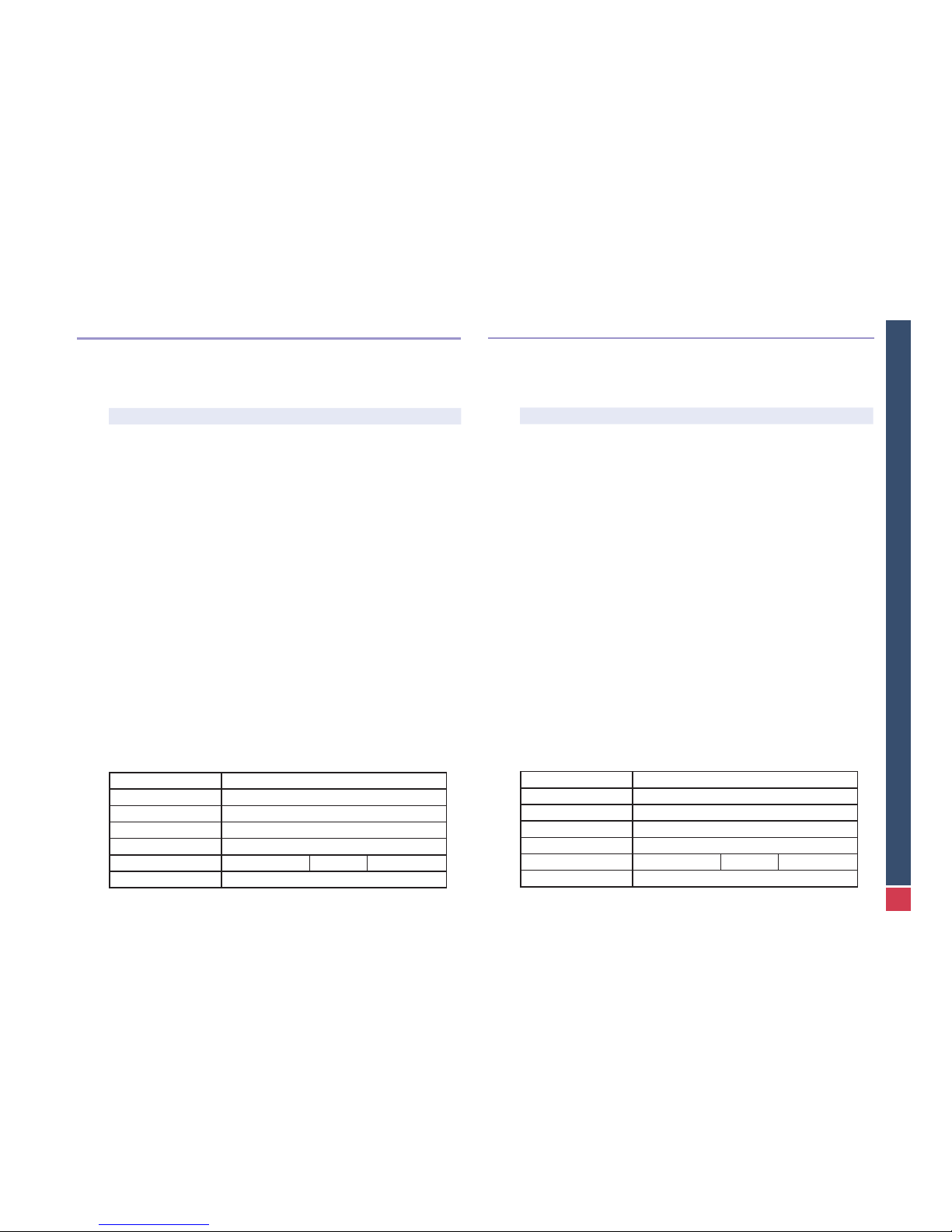
2.4. desCription
air flows:
A: Cold convection air
B: Hot convection air
V: Outside combustion air intake under the replace
V’: Outside combustion air intake at back of replace
W: Smoke removal area and accessory secondary combustion
X: Primary combustion
Y: Main secondary combustion
Z: Smoke
main parTs:
1. The door: Can go up or down in use, depending on the need.
2. The air control thermostat: Regulates the ow of primary
combustion air based on its setting. The ap opens and closes
depending on the temperature in the combustion chamber. The
control button is operated with the handle provided (cold hand).
The at end of the handle is placed in the air control notch to rotate
it: from left (0) to right (9) counter-clockwise.
3. Removable stainless steel cold hand. Used to adjust the ther-
mostat (at end) and to lift the window (round end).
4. Vermiculite or decorative metal: Protective plate of skamol or
painted stainless steel (black) which acts as an insulator. These
plates must be protected from dampness: a cap must be installed
on the chimney.
5. Bafes: Made of refractory stainless steel. They lengthen the
route taken by the smoke to optimise secondary combustion and
increase heat transfer. They enable adjustment of the replace to
the chimney’s draft.
6. Air distributors and channels: Provide even distribution of
primary air.
7. Deector: Keeps the window smoke-free.
2.4. desCription de L’appareiL
flux d’air inTerne:
A: Air froid de convection
B: Air chaud de convection
V: Prise d’air de combustion extérieure en-dessous du foyer
V’: Prise d’air de combustion extérieure arrière
W: Air de désenfumage et combustion secondaire accessoire
X: Combustion primaire
Y: Combustion secondaire principale
Z: Fumées
elemenTs principaux:
1. La porte: elle peut monter ou descendre en fonctionnement.
2. Le thermostat: Il règle la quantité d’air primaire pour la combustion en fonction de sa position. Son clapet se ferme et s’ouvre
en fonction de la température de la chambre de combustion. Son
bouton de commande se manoeuvre avec la poignée fournie (main
froide): l’extrémité plate de la poignée doit être placée dans l’encoche du thermostat pour lui faire subir un mouvement de rotation:
de gauche (0) à droite (9) dans le sens inverse des aiguilles d’une
montre.
3. Main froide amovible en Inox. Elle sert au réglage du thermostat
(bout plat) et au levage de la vitre (bout rond).
4. Vermiculite ou déco métal: Plaque de protection en skamolex
ou en métal inox peint (couleur noire) qui joue un rôle isolant. Ces
plaques doivent être protégées de l’humidité, d’où la nécessité d’installer un chapeau sur la cheminée.
5. Chicanes: En inox réfractaire, elles augmentent le trajet des fumées optimisant la combustion secondaire et augmentant le transfert de chaleur. Elles permettent une adaptation du foyer au tirage
de la cheminée.
6. Répartiteurs et canaux: Ils permettent une distribution régulière
de l’air primaire.
7. Deecteur: aide à garder la vitre propre.
A
B
B
V
V‘
W
X
Y
Z
4
5
1
2
3
6
7
7
PHENIX Green US
Version 12-40
2.5. OPENING-CLOSING
Open the replace door slowly when a re
is burning. Opening the door suddenly will
cause temporary smoke spill out. To close
the door: slide the handle in the door opening
and lower it with a slight movement of the arm
downward. The door movement is very light.
The window cannot handle the door being
opened and closed abruptly on a consistent
basis.
Keep the door closed except for lighting the
fire and adding logs.
2.6. USING THE FIREPLACE
The quality and dampness of the wood used are of utmost importance to making
an optimal re (yield and heating power, window cleanliness).
Quality wood:
- Is dry wood that has been seasoned for at least two years in a ventilated storage
area.
- Use hardwood logs rather than resinous ones which tend to burn quickly and produce a lot of soot. By order of preference use: oak, beech, ash or maple.
- Logs made from natural pressed wood chips, or briquettes, can also be used.
WARNING: Overloading will result in:
- A lower yield and greater wood consumption
- Signicant loss of heat through the chimney
- Premature aging of the replace and of the chimney ue
2.5. OUVERTURE-FERMETURE
Porte: Pendant le feu, ouvrez la porte du foyer
lentement. Une ouverture brusque provoque un
refoulement momentané du foyer. Pour refermer
la porte: glissez la poignée dans l’orice de la
porte et faites-la descendre avec un léger mouvement du bras vers le bas. Le mouvement de
la porte est très léger et la vitre ne supporterait
pas longtemps des ouvertures ou fermetures
trop brusques.
laissez la porte du foyer fermée en dehors de
l’allumage et de la recharge.
2.6. CONDUITE DU FEU
La qualité et le séchage du bois sont primordiaux pour le fonctionnement optimal
du foyer (rendement et puissance de chauffe, propreté de la vitre).
Un bois de qualité est :
- Un bois sec ayant séché au moins 2 ans sous abri ventilé.
- Privilégiez les bûches de feuillus au détriment des résineux ayant tendance à
brûler vite en produisant beaucoup de suie. Par ordre de préférence : le chêne, le
hêtre, le frêne ou l’érable.
- Il est possible d’utiliser aussi des bûches de copeaux de bois compressés ainsi
que des briquettes.
ATTENTION: Une charge de bois excessive entraîne:
- Une diminution du rendement et une augmentation de la consommation de bois.
- Une importante perte de chaleur par la cheminée.
- Un vieillissement prématuré du foyer et du conduit de cheminée.
8
PHENIX Green US
Version 12-40
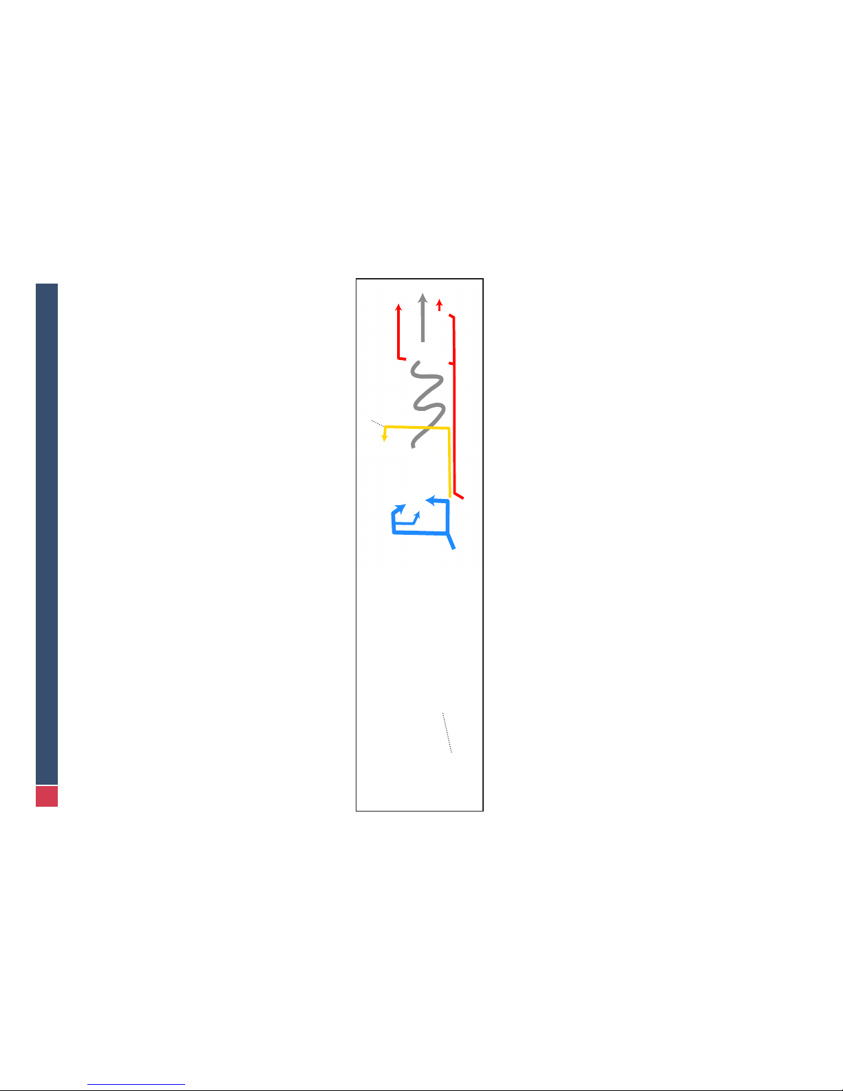
Starting a re
1. Fully open the air ow: position the air control on its
maximum using the tool-handle (see illustration right)
2. Put in re-starter or crumpled newspaper. Put kindling on top. Do not use ammable liquids to start the
re.
3. Light the re
4. To avoid smoke condensation on the window when
the re is lit: Leave the door slightly open to avoid smoking up the window. Its cooler temperature will cause
condensation and soot build-up.
5. Wait until the kindling is burning well then LOAD the rst
logs, starting with the smallest ones.
6. Shut the door when there are nice ames and the glass is
hot enough.
7. Once the replace is hot, set the air control to the desired
position.
Ideal burn rate for high yield
1. Use split logs (1 or 2 depending on the amount of heat needed).
2. Try to stagger the logs to promote the exchange of gases.
3. Set the air control on 7-8.
The wood is burning properly when, following a degassing period during which
the inside of the replace becomes black, the black tar burns off and the inside of
the replace becomes clear. The replace will blacken each time a new load of
wood is put in then clear up again.
For a better yield its best to set the air control to 7-8 and put each log in separately
depending on the amount of heat needed.
This will also help keep the glass, bricks and chimney cleaner.
Close the bafes as much as the chimney allows (see “Setting the bafes” in chap-
ter 2.7.).
Allumage correct
1. Placer le thermostat sur le maximum 9 en utilisant la
poignée outil (cfr. illustration ci-contre)
2. Déposer allume-feu ou papier journal chiffonné. Compléter avec du petit bois d’allumage. L’utilisation de li-
quides inammables est interdite.
3. Mettre à feu.
4. Pour éviter la condensation des fumées sur la vitre au
démarrage: Laisser la porte légèrement entrebaillée pour
éviter l’encrassement de la vitre dont la température en-
core trop basse.
5. Attendre que le petit bois soit bien enammé et CHARGER les
premières bûches (les plus petites).
6. Dès qu’il y a de belles ammes et que la vitre est sufsamment
chaude, fermer complètement la porte.
7. Lorsque l’appareil est bien chaud, régler le thermostat sur la
position désirée
Allure idéale pour un rendement optimal
1. Choisir des bûches fendues (1 ou 2 suivant la chaleur nécessaire).
2. Essayer de les empiler en quinconce pour favoriser les échanges gazeux.
3. Mettre le thermostat sur 7-8.
Signe d’une bonne combustion avec du bois: après une phase de dégazage
où l’intérieur du foyer devient noir, ce goudron noir doit être brûlé pendant la combustion proprement dite, et l’intérieur du foyer doit apparaître clair, pour se noircir
à nouveau à la charge suivante et ensuite être à nouveau rebrûlé.
Pour un meilleur rendement, il vaut mieux avoir un thermostat sur 7-8 et charger
bûche par bûche en fonction de la quantité de chaleur dont vous avez besoin.
Ceci permet également de garder la vitre ainsi que les briques et la cheminée plus
propres.
Veiller également à fermer le plus possible les chicanes si votre cheminée le permet (voir «Réglage des chicanes» ci-après).
0
1
2
3
4
5
6
7
8
9
9
PHENIX Green US
Version 12-40
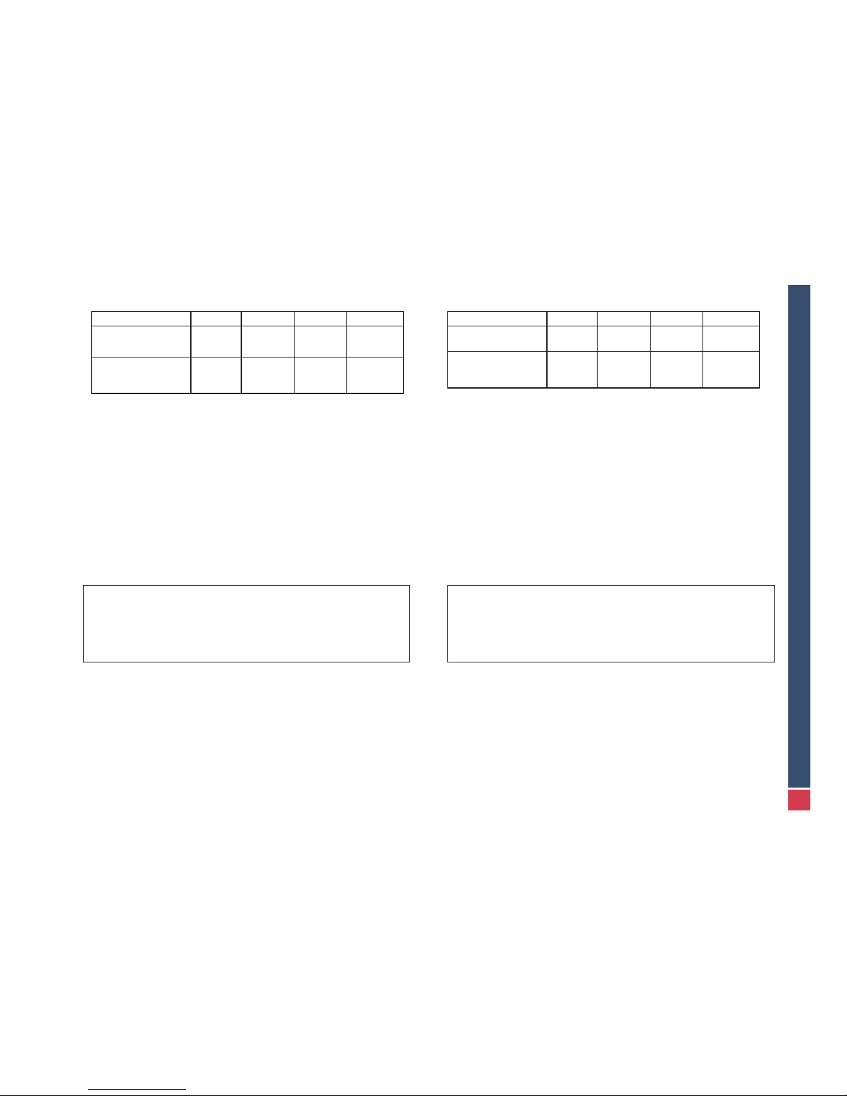
Maximum allowable load (wood logs)
Model Phenix 75 Phenix 85 Phenix 95 Phenix 120
Maximum load for slow
burn
13 lb
(6 kg)
15
1/2
lb
(7 kg)
20 lb
(9 kg)
22 lb
(10 kg)
Recommended load
per hour at maximum
rate
7 lb
3.2 kg)
9 lb
(4 kg)
10 lb
(4.4 kg)
11 lb
(5 kg)
Slow burn rate and long-lasting combustion
Maximum allowable single load at low burn rate (see table above)
1. Keep a bed of embers 1
1/2
to 2’’ (3 to 5 cm) thick on the oor of the replace.
2. Select wide-cut logs.
3. Set the air control according to your chimney’s draft. This will normally be 1 to 3
for a slow burn rate.
This load can only be used for a slow burn rate to maintain a long-lasting re.
Parallel stacking of logs will help the re burn longer. Put more wood in when only
embers remain, just after the ames have disappeared.
WARNING: Continual use of the replace at a slow burn rate can cause an
accumulation of soot in the chimney due to condensation. This can lead
to a chimney re and also dirties the glass.
Avoid making a slow-burning re when atmospheric conditions are not
favorable (i.e. low pressure and high humidity) as this can cause smoke
to spill out.
Charge maximale autorisée (bois en bûche)
Modèle Phenix 75 Phenix 85 Phenix 95 Phenix 120
Charge maximale
(pour allure réduite)
6 Kg
(13.2 lb)
7 Kg
(15.4 lb)
9 Kg
(19.8 lb)
10 Kg
(22 lb)
Charge conseillée
pour 1heure à allure
maximale
3.2 Kg
(7 lb)
4 Kg
(8.8 lb)
4.4 Kg
(9.7 lb)
5 Kg
(11 lb)
Allure réduite et combustion longue durée
Charge maximale autorisée en une fois en allure réduite (voir tableau précédent).
1. Conserver un lit de braises de 3 à 5 cm (1.25 à 2’’) sur le fond du foyer.
2. Choisir des bûches de très grosse section.
3. Positionner le thermostat en fonction du tirage de votre cheminée. Une allure
réduite s’obtient généralement de 1 à 3.
Une telle charge ne peut être utilisée qu’à une allure réduite, an d’obtenir un feu
de longue durée.
L’empilement parallèle des bûches favorise un feu de longue durée. Recharger
lorsqu’il ne reste que des braises, juste après la disparition des dernières ammes.
ATTENTION: L’utilisation permanente en allure réduite peut, par condensation, provoquer une accumulation de suie dans la cheminée donc, un
risque de feu de cheminée et favorise le salissement de la vitre.
Eviter l’allure réduite lors de conditions atmosphériques défavorables
(basse pression et humidité élevée) car un refoulement est à craindre.

10
PHENIX Green US
Version 12-40
2.7. settinG and usinG tHe BaffLes
Set the bafes according to your chimney’s
natural draft. The factory setting will have
to be adjusted if it does not allow for the
right draft and a good yield. The replace
has three adjustable bafes (C1, C2 and
C3 below) and a removable deector (D).
On delivery, the bafes assembly will be in
open position with the deector installed.
Full ow position:
This enables easy ow of smoke. Each
bafe consists of a xed support on which
two panels slide. When the two panels are
brought back to the center of the support,
the passageway on the sides is opened up
for smoke.
Note: When the chimney draught is very
weak, it is possible to further increase the
amount of smoke passing through by taking out the detector (to do so, lift, turn 90°
and lower between the walls in the combustion chamber).
Intermediate position
If no smoke comes out of the replace when
it is opened, the bafes can be closed more
to improve yield. To do this, slide the upper
panels of one (or more) bafes to separate
them a bit.
2.7. reGLaGe et manipuLation des CHiCanes
Un bon réglage est fonction du tirage naturel
de votre cheminée. Il faudra donc adapter le
réglage d’usine si celui-ci ne vous permet pas
d’obtenir un tirage correct et un bon rendement. L’appareil comporte trois chicanes réglables (C1,C2 et C3 ci-dessous) et un déecteur amovible (D). A la livraison, l’assemblage
des chicanes est en position fermée avec le
déecteur en place.
Position la plus ouverte
Celle-ci permet un passage aisé des fumées.
Chaque chicane est constituée d’un support
xe sur lequel coulissent deux panneaux:
lorsque les deux panneaux sont ramenés vers
le centre du support, le passage sur les côtés
est dégagé pour les fumées.
Note: Lorsque le tirage de la cheminée est
vraiment très faible, il est possible d’augmen-
ter encore le passage des fumées en enlevant le déecteur (pour cela, le soulever
et le faire pivoter à 90° pour pouvoir le redescendre entre les parois dans le corps
de chauffe).
Position intermédiaire
Si aucun refoulement à l’ouverture n’est observé, il est possible de fermer un peu les
chicanes pour augmenter le rendement. Pour
cela il suft de faire coulisser les panneaux
supérieur d’une (ou plusieurs) chicane(s) pour
les écarter un peu.
D
C1
C2
C3

11
PHENIX Green US
Version 12-40
Fully closed position
If there is no smoke spill out in the
intermediate position, close the
bafes completely to obtain the
best yield the replace can provide
for the chimney. To do this, fully
separate the upper panels of the
bafes to decrease the outow of
smoke and ensure maximum combustion of the gases.
The bafes are set on top of the supports integrated in the replace. To remove
them, lift then twist slightly to bring them toward the bottom. Follow the steps in
reverse to put them back.
CHIMNEY SWEEPING! CAUTION!
Don’t forget to remove the deector during chimney cleaning to clean
off any ash that has settled on it! Put it back on its support before repo-
sitioning the bafes.
Don’t forget to record the position of the bafes before removing them
to enable correct repositioning.
Position la plus fermée:
Si il n’y a toujours aucun refoulement
en position intermédiaire, fermer au
maximum les chicanes, pour obtenir le
meilleur rendement que le foyer peut
donner par rapport à la cheminée.
Pour cela, écarter au maximum les
panneaux supérieurs des chicanes
pour diminuer le passage des fumées
et garantir une combustion maximum
des gaz.
Les chicanes étant simplement posées sur des supports intégrés à l’appareil, il
suft pour les enlever de les soulever puis de les faire pivoter légèrement pour
les ramener vers le bas. Procédez de manière inverse pour les replacer.
RAMONAGE! ATTENTION!
Lors du ramonage de la cheminée, ne pas oublier d’enlever le déec-
teur pour le débarrasser des cendres qui s’y accumulent! Replacez-le
ensuite sur ses supports avant de repositionner les chicanes.
N’oubliez pas de noter la position des chicanes avant de les enlever
pour être certain de les remettre correctement.

12
PHENIX Green US
Version 12-40
3. MAINTENANCE
3.1. onGoinG maintenanCe
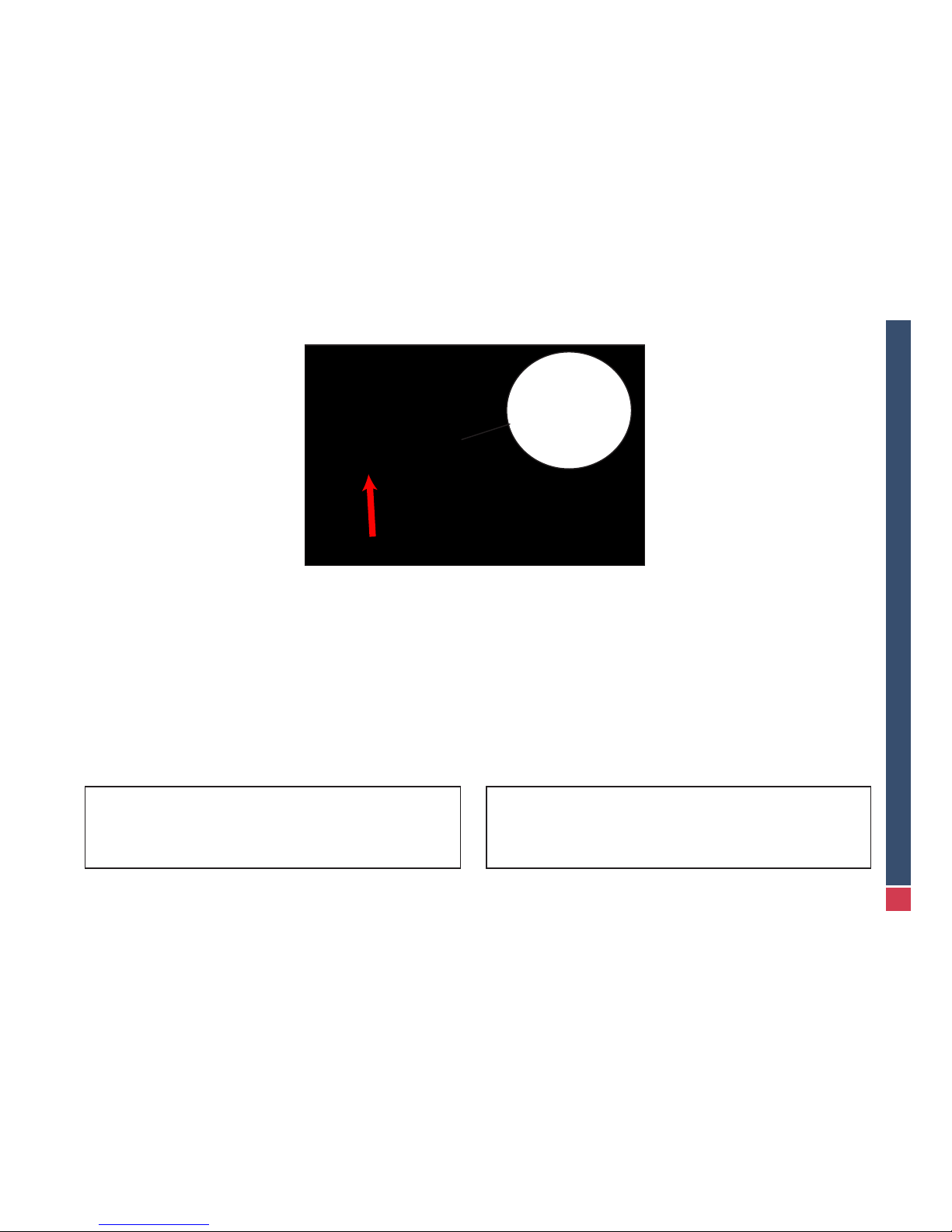
WINDOW
To clean the window, begin by completely closing the door. Next, ip up the 2 hooks
located on either side of the top of the door (1) and tilt the window out forward (2).
WARNING!
- Do not clean the window when it is hot.
- Spray a suitable cleaning product in the middle of the window then spread it
with an absorbent cloth or paper towel. We recommend that you use a cleaning product that contains no caustic soda and is biodegradable
- Do not use water and/or cleaning products on painted areas.
- A blade for glass ceramic cook tops can be used to clean difcult areas.
- Cleaning the glass is easier when done on a regular basis and when res are
well-managed.
3. ENTRETIEN
3.1. entretien Courant
VITRE
Pour nettoyer la vitre, commencez par fermer la porte entièrement. Ensuite déga-
gez les crochets situés de chaque côté en haut de la porte (1) et basculez la vitre
(2).
ATTENTION !
- Ne pas nettoyer une vitre chaude.
- Vaporiser le produit d’entretien adapté au centre de la vitre, ensuite étaler ce
produit avec un chiffon ou un papier absorbant.
- Ne pas utiliser d’eau et/ou de produits nettoyants sur les parties peintes.
- Pour des traces tenaces, il est possible d’utiliser une lame à gratter pour table
de cuisson vitrocéramic.
- Le nettoyage de la vitre est plus facile s’il est régulièrement effectué et que la
conduite du feu est bien menée.
1
2

13
PHENIX Green US
Version 12-40
AIR DISTRIBUTORS/INTAKE CHANNELS
If required, unplug the air intake holes of the front air distributor with a vacuum
cleaner and those located between the vermiculite plates on the oor which can be
easily removed for ease of cleaning.
AIR CONTROL THERMOSTAT
Check that it opens correctly depending on the burn rate of the re. Your dealer is
trained to check the settings.
DOOR
Check the condition of the door gaskets around the glass.
If required, your dealer can adjust and/or replace them. Check that the door closes
properly and opens safely. This will help ensure a high yield and a clean window.
Also, periodic lubrication of the door mechanism and chains may be required.
Contact your local dealer or chimney sweep.
REPARTITEURS ET ENTRÉES D’AIR
Déboucher, au besoin, les trous d’arrivée d’air du répartiteur frontal avec un aspirateur, ainsi que ceux situés entre les briques du sol et qui peuvent être facilement
enlevés pour faciliter l’opération.
THERMOSTAT
Vérier que son ouverture se fait de manière correcte en fonction de l’allure du feu.
Votre fournisseur est habilité à vérier le réglage.
PORTE
Vérier l’état des joints en céramique autour de la vitre.
Au besoin, votre fournisseur peut en assurer le réglage et/ou le remplacement.
Vériez le fonctionnement correct de la fermeture et de l’ouverture. Ceci an d’assurer un bon rendement et une vitre propre.
Un graissage régulier du mécanisme d’ouverture et des chaînes est recommandé.
Contactez votre revendeur ou ramoneur.

14
PHENIX Green US
Version 12-40
3.2. yearLy maintenanCe
CHIMNEY SWEEPING
Have the chimney cleaned at least once a year both to meet regulations and
for safety.
- Note the placement of the bafes.
- Take apart the bafes and deector as shown in section 2.7.
- Close the door and shut down the air control (if the chimney is swept from the
roof).
- Vacuum after the soot has dropped (don’t forget to clean the deector).
T ake advantage of cleaning to check the condition of the chimney and connections.
- Follow the instructions in reverse to reposition the bafes. Be careful to reset them
to their original installed positions.
PAINT ON METAL SURFACES
Do not use water and/or cleaning products on painted areas.
Soiled areas can be restored with special high temperature aerosol paint available
from your dealer.
VERMICULITE PLATES (SKAMOLEX) OR DECORATIVE METAL
A split brick can still fulll its protective function. However, if a piece is missing, the
brick should be replaced to provide adequate protection for the combustion chamber. The bricks are easy to replace individually. It is recommended that damaged
ones be replaced. Decorative plates of painted metal can be replaced individually
if damaged.
3.2. entretien annueL
RAMONAGE
Faire ramoner au minimum 1 fois l’an, non seulement pour rester dans la
légalité, mais aussi par souci de sécurité.
- Prendre note de la position des chicanes
- Démonter les chicanes, comme indiqué dans le paragraphe 2.7.
- Fermer la porte et le thermostat (si le ramonage se fait par la toiture).
- Après retombée des poussières, il sufra de les récolter à l’aspirateur (sans ou-
blier de vider le déecteur).
Proter du ramonage pour contrôler l’état de la cheminée et du raccordement.
- Repositionner les chicanes en suivant les instructions inverses et en prenant
garde de bien les repositionner comme précédemment.
PEINTURE DES PARTIES METALLIQUES
Ne pas utiliser d’eau et/ou de produits nettoyants sur les parties peintes.
Les endroits souillés peuvent être restaurés au moyen de peinture spéciale haute
température en aérosol, disponible chez votre distributeur.
PLAQUES EN SKAMOLEX OU DECO METAL
Une brique fendue peut toujours jouer son rôle protecteur. Cependant, un morceau manquant entraînera le remplacement pour conserver une protection ef-
cace du corps de chauffe. Les briques sont des pièces d’usure facilement remplaçables individuellement. Il est conseillé de changer une pièce trop abîmée. Pour
les plaques décoratives en métal peint, il est possible de les remplacer pièce par
pièce si l’une d’elles est endommagée.

15
PHENIX Green US
Version 12-40
4. INSTALLATION
4.1. adapter Kit for us and Canadian marKets
To comply with UL and ULC national standards, all parts of the adapter kit
must be installed on the appliance as shown in the instructions described in
the Annex of this document.
We recommend that your Phenix Green replace is installed by qualied installers and according to UL/ULC standards and the local building codes.
4. INSTALLATION
4.1. adaptation pour Les marCHes us et Canadiens
Pour être conforme aux normes d’installation locales, il est impératif d’installer sur le foyer les éléments du kit d’adaptation spécialement prévu, selon
les instructions données en annexe.
Nous recommandons que nos appareils soient installés par des professionnels agréés dans le respects de la règlementation locale en vigueur.
4.2. CHimney fLue
Chimney systems approved for the Phenix Green Fireplaces are the Class A
UL-103 approved factory-built chimney system or the Heatilator brand UL
approved air cooled chimney system. An approved masonry chimney that meets
local codes may also be used.
4.2. Conduit de fumees
Le conduit de cheminée doit être construit avec des matériaux de classe A
UL-103 ou le système approuvé Heatilator UL. Un conduit maçonné suivant les
règles locales en vigueur peut également être utilisé.
Min 3’
Min 2’
< 10’
20°- 45°
OK!
OK!
45°
20°-30°
45°
30°

16
PHENIX Green US
Version 12-40
The Chimney must extend at least 3 feet (915 mm) above its point of contact with
the roof and at least 2 feet (610 mm) higher than any roof or wall within 10 feet (3
m).
THERE MUST BE A 2 INCH (5 CM) CLEARANCE BETWEEN THE CHIMNEY
AND ANY COMBUSTIBLE MATERIALS. DO NOT FILL THIS SPACE WITH INSULATION OR ANY MATERIAL.
Refer to the recommendations from the Chimney Manufacturers for more information on installation and use.
RECOMMENDATIONS
The chimney ue must be built in compliance with industry practices of which the
following are the most important:
- Minimum height: (distance between the connection at the appliance and the top of
the chimney stack) should be 16½ ft (5 m) to achieve a proper draft.
- Maximum height: Refer to the Chimney Manufacturer’s specications.
- Section:
Chimney diameter: Phenix 75 - 8’’ (200 mm)
Phenix 85, 95 and 120 - 10’’ (250 mm)
Hot air vent diameter: 6’’ (150 mm)
Outside air intake adapter diameter: 4½’’ (110 mm)
- The chimney stack and its positioning are very important. The chimney must have
a cap to prevent rain water from entering the replace. Ask the advice of a chimney expert (devices that narrow the smoke outlet must be avoided).
- The chimney outlet must be protected from wind disturbances.
- The presence of obstructions near the chimney outlet must be taken into account
- An individual ue cannot change directions more than twice. The angle of these
changes to the vertical must generally not exceed 20° or 30°.
- The ue should enable recovery of soot (easily cleanable).
- Connect only one replace per ue
FIREPLACE-CHIMNEY CONNECTION USING AN EXISTING FLUE:
It is standard practice to check for water tightness, any blockage, general stabi-
lity, and replace compatibility (diameter-section) and, if required, the ue must be
lined and the stack modied. Contact your local dealer or chimney professional for
additional advice.
La cheminée doit dépasser de minimum 3 pieds (915 m) son point de contact avec
le toit et de minimum 2 pieds (610 m) tout mur ou toit situé dans un rayon de 10
pieds (3 mètres).
UN ESPACE LIBRE (= VIDE) DE MINIMUM 2 POUCES (5 CM) DOIT ETRE MAINTENU ENTRE LE CONDUIT ET TOUT MATERIAU COMBUSTIBLE.
Consultez le fabricant du conduit pour toute information sur son installation ou son
utilisation.
RECOMMANDATIONS
Le conduit doit être conçu selon les règles de l’art dont voici les plus importantes:
- Hauteur minimale (distance entre raccordement et dessus de souche) sera de
16.5 ft (5 m) pour assurer un tirage correct
- Hauteur maximale: voir spécication du conduit selon son fabricant.
- Section:
Diamètre cheminée: Phenix 75 - 8’’(200mm)
Phenix 85, 95 and 120 - 10’’ (250 mm)
Diamètre buses de convection: 6’’ (150 mm)
Diamètre buselot prise d’air extérieur: 41/2’’ (110 mm)
- La sortie de la cheminée (souche) et son emplacement sont très importants, il faut
absolument que la sortie dispose d’un chapeau pour éviter qu’il pleuve dans le
foyer. Demander conseil à un cheministe (tout dispositif rétrécissant la section de
sortie doit être évité).
- La sortie de cheminée doit se trouver hors des zones d’inuence des vents.
- La présence d’obstacles à proximité de la sortie doit être prise en compte.
- Un conduit de fumée individuel ne comporte pas plus de 2 dévoiements (autrement dit, changements de direction). L’angle de ces dévoiements avec la verticale
ne doit pas excéder d’une façon générale 20° à 30°.
- Le conduit doit permettre la récupération des suies (ramonable).
- Ne raccorder qu’un seul appareil par conduit.
POUR UN CONDUIT EXISTANT:
Il est de rigueur de vérier, outre l’étanchéité, le dégagement et la stabilité générale,
la compatibilité du foyer (diamètre-section) et si nécessaire, tuber le conduit, voire
modier la souche. Contactez un professionnel pour tout conseil.

17
PHENIX Green US
Version 12-40
4.3. BuiLt-in CHase (framinG)
A 2” (5cm) clearance must be kept around the replace sides, b ottom, and back.
The US/Canada adapter kit is speci
cally designed to keep those clearances.
An insulated
panel (minimum ½”/10 mm thick) must also be placed over the
upper portion of the front of the appliance with a minimum 1½” (38 mm) air
space between the replace and the insulated panel in order to protect the
face covering. The insulated panel could be any noncombustible material
such as cement board or vermiculite/skamol. This panel is not supplied with
the appliance. Refer to the diagram at the end of this section.
Note that the frame around the replace is not load bearing – thus nothing should
be directly attached or resting on the frame. The frame can replaced with a narrower or wider frame to accommodate the façade application (e.g. tiles or wood
paneling).
Keep a minimum 1/16” (2.5mm) clearance between the metal frame and the front
covering to allow for expansion of the frame.
Above the replace: do not put any brickwork on the replace. Under the replace:
leave enough space for convection air circulation (required minimum 2”/50 mm).
CAUTION: The chase/framing for the replace must have sufcient air intakes to
allow for the air ow required for the operation of the replace and the ventilation
of the chase.
In some areas it is required that the replace unit be attached to the chase. Either
a strapping band or L-bracket is suggested to secure the unit to the framing/oor.
Refer to the Framing Specications in the Technical Drawings section of the Annex
for detail dimensions.
TYPE OF MATERIALS
CAUTION - COMBUSTIBLE MATERIALS:
Must not be placed in the immediate vicinity of the replace, of the hot air outlets,
or of the chimney ue. Note: hot embers can be projected several feet/meters
when the door is opened or when using the fireplace with the door open.
The fireplace unit must be placed on a non-combustible floor and must
meet the minimum clearance requirements.
NON-COMBUSTIBLE AND INSULATING MATERIALS:
Use “HIGH TEMPERATURE” materials such as rock wools. These materials must
not come into contact with the convection air (DO NOT USE FIBERGLASS).
If the replace is set against an outside wall of the house, it is advisable to insulate
the exterior wall from the replace to avoid heat loss.
4.3. enCastrement/ HaBiLLaGe
Une distance de sécurité doit être absolument être respectée entre le foyer et tout
matériau situé autour de lui. Le kit d’adaptation USA est prévu notamment pour
maintenir l’écart minimum nécessaire mais:
Il faut également prévoir de placer un panneau en matériau isolant non combustible de minimum 10 mm-1/2’’ d’épaisseur devant le foyer, an de protéger
l’habillage de la façade. Ce panneau isolant, fait de matériau non combustible (ciment
ou vermiculite par exemple) n’est pas fourni avec l’appareil (voir
schémas d’encastrement ci-après).
Ne
rien xer au cadre de l’appareil qui pourrait l’alourdir. Le cadre peut être rem-
plaçé par un autre modèle plus n ou épais selon l’effet souhaité (matériaux déco-
ratifs).
Au-dessus de l’appareil: ne pas poser de maçonnerie sur le foyer. Sous l’appareil:
prévoir un espace sufsant pour la circulation le l’air de convection (50 mm/2’’).
Un espace libre de minimun 1.5 mm-1/16’’ doit être prévu entre le bord du cadre et
la maçonnerie (dilatation possible du cadre à la chaleur).
ATTENTION: La conception de l’habillage du foyer doit permettre la circulation des
différents ux d’air nécessaires au fonctionnement de l’appareil et à la sécurité de
l’installation (en fonction de la conguration choisie).
Dans certaines régions, le foyer doit être xé à la structure de son habillage (crochet
riveté, patte de maintien ou autre)
Consultez les schémas techniques en annexe pour les dimensions d’encastrement.
TYPES DE MATERIAUX
ATTENTION: MATÉRIAUX COMBUSTIBLES
:
Ils sont à proscrire dans l’environnement immédiat du foyer, des sorties d’air
chaud et du conduit de cheminée. Il faut noter que, à l’ouverture de la porte,
ainsi qu’en fonctionnement «porte ouverte», des braises brûlantes peuvent être
projetées à plusieurs mètres.
Le foyer doit être placé sur un sol non-combustible pour autant que les distances
de sécurité soient respectées.
MATERIAUX NON COMBUSTIBLES ET MATÉRIAUX ISOLANTS:
Utiliser des matériaux “HAUTE TEMPÉRATURE” comme certaines laines de
roche. Dans tous les cas, ces matériaux ne doivent pas être en contact avec l’air de
convection (NE PAS UTILISER DE LAINE DE VERRE).
Si le foyer est contre un mur extérieur de la maison, il est cependant préférable de
l’isoler de ce mur pour éviter une perte de chaleur.

18
PHENIX Green US
Version 12-40
MINIMUM SAFETY CLEARANCES
A. Distance to a combustible adjacent sidewalls, bottom, and back: 2” (5 cm)
B. Front protection to unprotected combustible oor: 18’’ (46 cm)
C. Side oor protection: 8” (20 cm)
D. Distance to furniture: 36’’ (91 cm)
Refer to the drawings on the next pages for further clarication.
DISTANCES DE SECURITE MINIMALES
A. Distance au mur latéral en matériau combustible et arrière: 2’’ (5 cm)
B. Protection frontale pour un sol combustible non protégé: 18’’ (46 cm)
C. Protection latérales du sol: 8’’ (20 cm)
D. Distance aux meubles: 36’’ (91 cm)
Pour plus de détails, consultez les schémas des pages suivantes.

19
PHENIX Green US
Version 12-40
B
C
3
4
5
6
7
MIN 0,6 INCH
MIN 30,8 INCHES
MIN 2,5 INCHES
MIN 8 INCHES
MIN 8 INCHES
top covering and floor protection characteristics
/
caractéristiques du panneau de couverture et de la
protection du sol
side & height clearances
/
distances lateriales & hauteurs
floor protection
B
C
D
0
1
2
3
4
5
6
7
E
Sol non combustible ou protection
Insulation or noncombustible oor
B
C
D
clearance for furniture and floor protection/
distance au mobilier et protection du sol
MIN 3/4’’ (15 mm)
MIN 31’’ (78 cm)
MIN 2½’’ (6 cm)
MIN 8’’ (20 cm)
MIN 8’’ (20 cm)

20
PHENIX Green US
Version 12-40
min 5,9 / max 10
MIN of 23.5 square inches free air inlet opening
MIN of 15.5 square inches free air outlet opening
B
C
D
0
1
2
3
4
5
6
7
ALWAYS PLUGGED
AIR FLOW
MIN 0,5 INCH INSULATED MATERIAL
MIN 2,6 INCHES
+
MIN 2 INCHES
B
C
2
3
4
5
Min 0,1 inch
Min 0,1 inch
clearance between front convering and frame
/
ecart entre cadre et façade d’habillage
front and bacK clearances
/
ecarts avant et arrière
MIN 1/16’’ (1.6mm)
MIN 1/16’’ (1.6mm)
MIN 2’’ (5cm)
FRONT FACING, e.g. sheetrock
AIR FLOW = MIN 1½’’ (38 mm)
INSULATED MATERIAL= MIN
½’’ (13mm)
Min 2’’ (5 cm)
between appliance and
bacK of front panel
MIN 2’’ (5 cm)
for combination of
air flow and insulated material
METAL
FRAME
APPLIANCE
MIN 2’’ (5cm)

21
PHENIX Green US
Version 12-40
D
E
A
B
A = 9 ¾“/248mm
B = 3 ½“/80.5mm
B
A = 9 ¾“/248mm
B = 3 ½“/80.5mm
A
E Inlet
D Inlet
Combustion air inlets
4.4. required air fLoW
In order to operate correctly, the replace needs air for three different purposes:
for wood burning combustion, circulation to heat the room, and ventilation (heat
management) to prevent overheating of the replace. In order for the air to
circulate properly and do its work, the air intakes and outlets must be large
enough and suitably positioned.
COMBUSTION AIR
The replace can be connected to an outside air intake or draw air from the
room to feed the re (possible air inlets E and D shown below).
OUTSIDE AIR INTAKE
The replace is airtight to the room when the door is closed, i.e. it is passive
house approved. The replace has two 4½” (110 mm) diameter wide openings:
One must be connected and the other plugged. The connection is made with a
PVC or metal pipe. The pipe can be up to 23 ft (7 m) long with one 90° elbow
or 16½ ft (5 m) long with three 90° elbows. Refer to the next section for further
discussion and installation procedures.
4.4. fLuX d’air neCessaires
Pour fonctionner correctement, ce foyer a besoin d’air à trois niveau: pour la combustion du bois, pour chauffer l’habitation, pour prévenir toute surchauffe de l’appareil.
Pour que l’air circule correctement et assure son rôle, il faut que les entrées et les
sorties d’air soient de tailles sufsantes et placées au bon endroit.
AIR DE COMBUSTION
Ce foyer peut être raccordé sur une prise d’air extérieur ou utiliser l’air de la pièce pour
alimenter le feu (localisation des prises d’air possibles D et E ci-dessous).
PRISE D’AIR EXTERIEUR
En cas de raccord sur une prise d’air extérieur, le foyer est étanche avec la pièce
lorsqu’il fonctionne en porte fermée (approuvé “Maison passive”). L’appareil est pourvu de deux orices de 110 mm/4.5’’ de diamètre: vous ne devez raccorder qu’un seul
des deux, au choix, et laisser le second fermé. Pour le raccord, vous pouvez utiliser
un tuyau en PVC ou un exible métal, d’une longueur maximum de 7 m/23ft avec un
coude de 90° et 5 m/16.5ft avec trois coudes de 90°.

22
PHENIX Green US
Version 12-40
A
D
INSIDE AIR INTAKE
To use air from the room in which the replace is located for combustion, use one of the two openings as an
air intake. An air intake must then be planned for in the
chase of the chimney. The entry point for the air intake
must be at least 18.6 in
2
/120 cm² in area. For example,
this is equivalent to a 4½” (11cm) side square or a 5”
(13cm) diameter circular opening.
The minimum will increase when a grille or lter is used
(for example: a grille that reduces the ow by 20% means
the minimum would be 23 in
2
/150 cm² in area, e.g. 5”
(13cm) side square or a 5½” (14cm) diameter circular
opening).
In this air ow conguration, the combustion air intake
and the convection air intake can be coupled (see diagram), but the two mini-
mum sizes must be combined to ensure that the two air intakes are sufciently
supplied. The ideal solution is, however, to have two separate intakes (of suf-
cient size) for each of the circuits and to channel the combustion air by using
a duct to connect the replace opening selected with the air intake in the box.
When the replace burns wood using combustion air from the room, it uses up
the room’s air. This air exits via the chimney (D).
This must therefore be compensated for with the usual intakes (A and B). If
these are not sufcient, a new fresh air intake must be added (C). Using a ventilation hood in the same living space creates an additional air outlet (D’), which
must also be compensated for.
This intake should preferably be located near the replace. This is to avoid cold
drafts across the room, negative air pressure in the room, and to contribute to
air renewal.
CAUTION: Insure that there is sufcient air ow to the house and rooms.
CONVECTION AIR (hot air circulation)
It is imperative that at least two (Phenix 75 and 95) or four (Phenix 85 and 120)
hot air vents located above the replace be connected (minimum 20”/50 cm
vertical ue).
The three air intakes located in the lower part of the back wall of the replace
must be open at all times.
Using the hot air vents on top of the replace: This enables extraction of heat
from the replace to send it to another room/rooms other than the one the
replace is in. In this case, the contribution of these outlets is about +/- 3.4KB-
PRISE D’AIR INTERIEUR
Si vous désirez utiliser l’air de la pièce où se trouve le foyer pour
la combustion, utilisez l’un des deux orices comme pour la
prise d’air extérieur. Une entrée d’air doit alors être prévue dans
l’habillage (caisson) de la cheminée. La taille de l’entrée doit être
au minimum équivalente à 18.6 in
2
/120 cm2 (= un carré de 4,5‘‘
ou un cercle de diamètre 5’’ par exemple). Ce minimum aug-
mente avec l’utilisation d’une grille ou d’un ltre (avec une grille
réduisant le ux de 20%, le minimum deviendrait 23in2/150 cm2).
En cas de convection naturelle, il est possible de coupler l’entrée
d’air pour la combustion et l’entrée d’air pour la convection (cfr.
ci-après) mais il faut additionner les deux tailles minimum pour
être certains que les deux circuits sont sufsamment alimentés. En cas de ventilation forcée, il est recommandé de prévoir
deux entrées différentes (et de taille sufsante) pour chacun des
deux circuits et de canaliser l’air de combustion en raccordant au moyen d’un conduit
l’orice choisi sur l’appareil à l’entrée d’air prévue dans le caisson.
Lorsqu’un foyer brûle du bois en prenant l’air de combustion dans la pièce, il consomme de l’air. Cet air sort par la cheminée D.
Il doit donc être compensé par les entrées habituelles, A et B, et si celles-ci sont in-
sufsantes, il faut ajouter une nouvelle entrée d’air frais C. La présence d’une hotte
aspirante dans le même volume d’habitation crée une sortie d’air supplémentaire D’,
qu’il faut également compenser.
De préférence, cette entrée sera proche du foyer. Ceci an d’éviter des courants d’air
froid à travers la pièce, une dépression dans le local et participer au renouvellement
de l’air.
IMPORTANT: vériez qu’il y a un renouvellement d’air sufsant dans la maison.
AIR DE CONVECTION (air chaud)
Il est impératif de raccorder deux des bouches d’air chaud situées au-dessus de
l’appareil pour les PHENIX 75 et 95, et les quatre bouches pour les PHENIX 85 et
120, à des conduits verticaux de minimum 50 cm/20’’ de hauteur.
Les entrées d’air situées dans le bas de la paroi dorsale de l’appareil doivent être
ouvertes.
Utilisation des bouches d’air chaud: Ceci permet d’extraire la chaleur du foyer et éventuellement d’en envoyer vers une autre pièce que celle où se trouve le foyer. Dans ce
dernier cas, l’apport de ces sorties demeure limité à +/- 1 KW/3.4 kBtu’s par sortie.

23
PHENIX Green US
Version 12-40
Convection air intake
Entrée d’air de convection
TUs/1 KW per outlet. The ducts, which should be thermally insulated, will
create a “draft” for the convection air. When the ducts are installed, limit their
length (maximum 8½ ft/2.5 m) and changes in direction. Make elbows as wide
as possible and use outlet grilles with the least resistance. The ducts cannot be
positioned downwards as this will go against the natural direction of hot air ow.
Keep a clearance of minimum 10”/25 cm between the ceiling and the center of
the convection grilles.
If hot air is sent to another room, an air return at least equal in area to the hot
air outlets should be provided.
HEAT MANAGEMENT SYSTEM - VENTILATION
Convection must be supplied by an air inlet in the lower
part of the chase. The minimum size is 93 in
2
/600 cm2
(open passageway). This is approximately a 10”/25cm
square. Any other shape can be used as long as the
minimum area is met. Also two inlets can be used. This
minimum size must be increased when using a grille or a
lter (if there is a 20% blockage then the minimum size is
116 in2/750 cm2 - about 11”/28cm square).
If the replace takes both its combustion AND its convec-
tion air from the same room, plan for air intakes in the
replace chase sufcient for the two air intakes (see diagrams).
VENTILATION OF THE CHASE
This air ensures that the replace will not overheat, potentially resulting in signicant damage. This ow of cold
air circulates from bottom to top inside and around the
replace.
The open space recommended enables ventilation air to ow around the re-
place. An air inlet of minimum 62 in
2
/400 cm² must be planned for at the bottom
and the top of the chase (in addition to the other air intakes mentioned above).
For example, 4 inlets of 4’’x4’’ (10x10 cm)on the top and bottom of each side
would be acceptable.
WARNING: A replace which is not correctly aerated/ventilated can
become deformed by overheating when it is used often at a high burn
rate. This type of deformation can signicantly hinder the operation of
the replace and even permanently damage it.
Les conduits, qui doivent être isolés isolés thermiquement, créent un “tirage” pour
l’air de convection. A l’installation de ces conduits, limiter la longueur (maximum 2,5
m/8
1/2
ft) et les changements de direction, “couder” au plus large et éviter l’utilisation de
grilles de sortie à faible coefcient de passage, car les pertes de vitesse engendrées
diminuent fortement l’efcacité des sorties d’air chaud. Ces conduits ne peuvent en
aucun cas descendre - cela irait à l’encontre du sens de la circulation naturelle de l’air
chaud. La distance entre le plafond et le centre de la grille d’air chaud doit être d’au
moins 25 cm/10’’.
Si de l’air chaud est envoyé dans un autre local, il est impératif de prévoir un orice de
retour d’air de section au moins équivalente aux sorties d’air chaud.
GESTION DE LA CHALEUR-VENTILATION
La convection doit être alimentée par une entrée d’air à prévoir
dans la partie basse de l’habillage. Sa taille minimum est de
600 cm²/93 in
2
(passage libre) et ce minimum augmente avec
l’utilisation d’une grille ou un ltre (grille avec diminution du ux
de 20% = minimum 750 cm2/116 in2).
Si le foyer prend son air de combustion ET de convection dans
la même pièce, prévoyez dans l’habillage du foyer des entrées
d’air sufsantes pour les deux circuits (cfr. ci-après).
AIR DE DECOMPRESSION
Cet air sert à éviter que le foyer ne surchauffe, ce qui pourrait
l’endommager fortement. Il s’agit donc d’un ux d’air froid qui
circule, de bas en haut, à l’intérieur et autour du foyer.
L’espace libre laissé entre le foyer et son habillage permet à l’air de décompression
de circuler autour de l’appareil. Une entrée d’air (minimum 400 cm²/62 in
2
) doit également être prévue dans le bas et le haut de l’encastrement (en plus des autres entrées
d’air mentionnées ci-avant). Quatre entrées de 10x10cm au-dessus et en dessous, de
chaque côté, seraient acceptable.
ATTENTION: un foyer qui n’est pas correctement aéré/ventilé risque de se
déformer sous l’effet de la surchauffe lorsqu’il est souvent utilisé en allure
vive. Une déformation de ce genre peut fortement entraver le fonctionnement
du foyer, voire même l’endommager irrémédiablement.

24
PHENIX Green US
Version 12-40
INSTALLATION CONFIGURATION: A FEW EXAMPLES
In all possible congurations, it
is essential to comply with the
minimum sizes for each of the
three air ows (combustion,
convection and ventilation).
Minimum size
Combustion: 19 in2/ 120 cm²
Convection: 93 in2/ 600 cm²
Ventilation: 62 in2/ 400 cm²
QUELQUES EXEMPLES DE CONFIGURATIONS POSSIBLES
Dans toutes les congurations possibles, il est essentiel
de respecter les tailles minimales pour chacun des trois
ux d’air (combustion, convection et décompression).
Taille minimum
Combustion: 120cm²/ 19 in
2
Convection: 600cm²/ 93 in
2
Décompression:: 400cm²/62 in
2
H
H
H
H, L: Minimum 5 cm H, L: Minimum 2’’
Insulating panel Panneau d’isolation
Insulating panel Panneau d’isolation

25
PHENIX Green US
Version 12-40
Convection
B
C
D
5
6
7
MIN 5,9 INCHES/MAX 10 INCHES
MIN 15,5 SQUARE INCHES (FREE)
Ventilation
A
B
The minimum sizes shown above are valid for completely open
passageways. When a grille or a lter is placed on the opening (at
entry or exit), the area of the entry or exit point must be increased
proportionally to accomodate the loss of air ow.
4.5. instaLL proCedures
- Ensure that the chimney is approved and thermally insulate the outside supporting
wall or combustible materials.
- Disassemble removable parts and, depending on the desired conguration, plug or
open up the openings provided for combustion and convection (refer to the Air Flow
section) using the plates provided.
- Place and position the replace in the recess at the correct height and LEVEL (left/
right and front/back). Leave 2” (5 cm) of space under the replace for air ow (refer
to the Built-In Chase Framing section) with an inlet of 93 in
2
/600 cm² of open space
minimum.
- Make the connection between the replace and the chimney then
connect the hot air collars (2 or 4).
- Plan for the combustion air inlet connection: use one of the two openings provided and close off the other one. If you are not using an
outside air inlet, follow the instructions from the Air Flow section. The
minimum air inlet sizes must be adhered to.
Side A of the connection part (see drawing on the right) is to be put in
the chosen air inlet and the brackets B are bent to maintain the connection part correctly.
Les tailles minimum indiquées ci-dessus sont valables pour des ori-
ces entièrement libres de passage. Lorsque l’on place une grille ou
un ltre sur l’orice (à l’entrée ou à la sortie), il faut augmenter la
surface de cette entrée ou sortie proportionnellement au coefcient
de passage de la grille (ou du ltre).
4.5. mise en pLaCe
- Vériez que la cheminée est conforme et isolez thermiquement le mur
d’adossement extérieur ou les matériaux combustibles.
- Démontez les pièces amovibles et, en fonction de la conguration souhaitée,
bouchez ou libérez les différents orices prévus pour la combustion et la convection (voir paragraphes “Flux d’air”) au moyen des plaques fournies (illustration ci-
contre).
- Introduisez et positionnez le foyer dans la niche: à hauteur et de NIVEAU
(gauche/droite et avant/arrière). Laissez 5 cm d’espace vide sous le foyer pour la
circulation de l’air (cfr. paragraphe «encastrement») avec une entrée de minimum
400cm² de passage libre.
- Effectuez le raccord entre le foyer et la cheminée puis raccordez les
buselots d’air chaud (2 ou 4).
- Prévoyez le raccordement de la prise d’air pour la combustion: utilisez
un des deux orices prévus et laissez l’autre fermé. Si vous n’utilisez pas
de prise d’air extérieur, suivez les instructions du chapitre “Flux d’air” et
respectez absolument les tailles minimales pour les entrées d’air.
La partie A du buselot de raccordement (illustration ci-contre) s’insère
dans l’orice choisi et les pattes sont écartées pour empêcher le buselot
de ressortir. Les pattes B sont ensuite également écartées pour empêch-

26
PHENIX Green US
Version 12-40
1
2
2
3
Positioning the bricks and metal panels
Top
Bottom
Assembling the
metal rods
- Set the bafes to the closed position (with no smoke spill) to obtain the best yield
from the replace (refer to the Setting and Using the Bafes section).
- The 4 mm frame must be positioned before the brickwork is done (refer to the Frame
section).
- It is recommended that a test be carried out PRIOR to doing brickwork around the
replace.
- Put the chase/covering on the replace. Be sure to provide the minimum sections
required for the air ow needed for combustion (inside connection), convection and
ventilation then dust the visible painted surfaces.
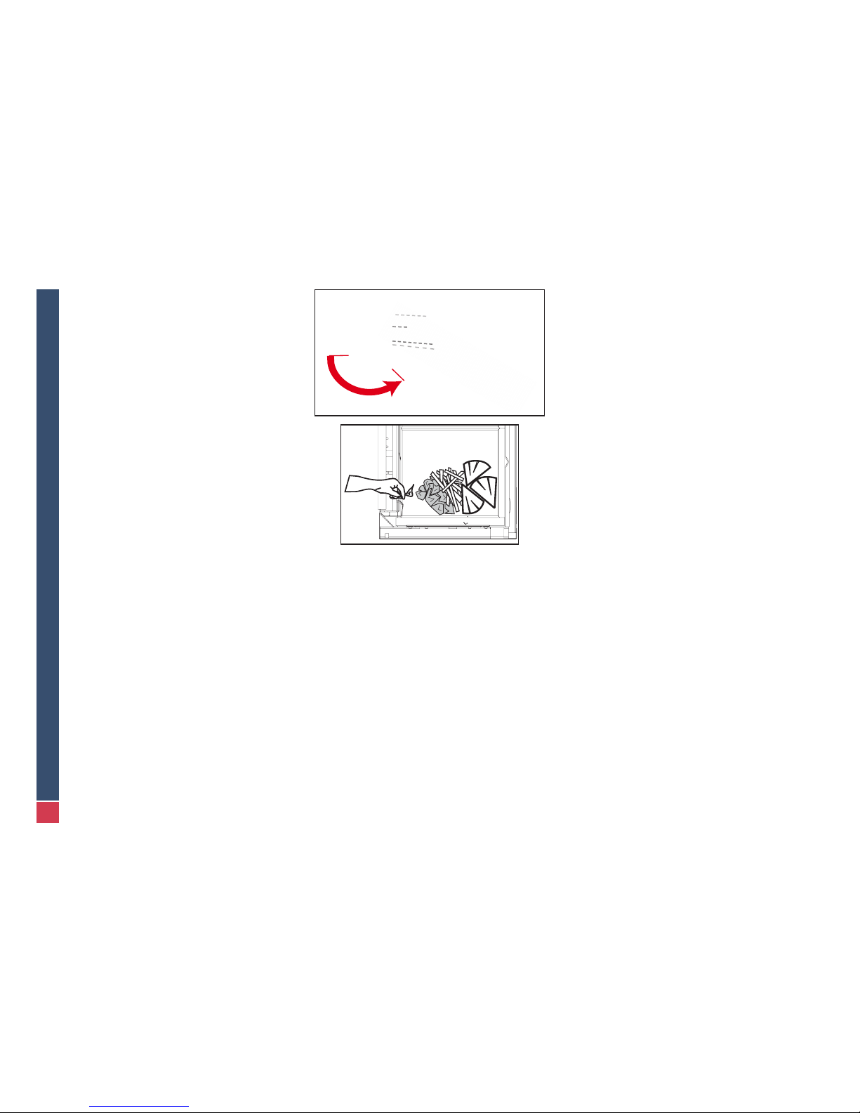
4.6. fireBriCK and deCoratiVe metaL
When doing the rebrick, rst position the
back bricks then the
lateral bricks under
the support foot (right
drawing) and, lastly, the
oor bricks with the air
distributors.
T o install the decorative metalwork (back and side walls only) assemble all of the metal rods to obtain the
back length then place the assembly by sliding it under
the support foot. Proceed the same way for the sides.
er le buselot de s’enfoncer dans le foyer.
- Placez les chicanes sur la position la plus fermée mais sans refoulement pour
obtenir le meilleur rendement du foyer. (voir dans le manuel d’utilisation: «Réglage
des chicanes»).
- Si vous avez choisi l’encadrement de 4 mm, il faut le placer avant d’effectuer la
maçonnerie (cfr. chapitre “Cadre”).
- Il est conseillé de faire un test de fonctionnement du foyer AVANT de maçonner
autour de l’appareil.
- Réalisez l’habillage de l’appareil en respectant les sections minimales pour le passage de l’air nécessaire pour la combustion (en cas de raccordement intérieur), la
convection et la décompression, puis dépoussiérez les surfaces peintes visibles.
4.6. Briques ou deCo metaL
Glisser d’abord sous les pattes
de maintien les briques ou les
lamelles métalliques du fond,
ensuite ceux des côtés et nir
en posant les briques du sol en
alternance avec les répartiteurs
d’air. Les trous percés dans les
briques/lamelles pour l’injection
d’air doivent être placés en bas.
Note pour l’installation de la déco métal sur les parois arrière et latérales: les lamelles s’accrochent les unes aux autres
pour former des panneaux.

27
PHENIX Green US
Version 12-40
PH
80 mm - 3 1/8’’
X 4
Prole
4.7.
frame (optionaL)
The 4 mm frame must be placed before brickwork is done. The 4 mm frame is
fastened to the replace with four screws.
Take external dimensions of the frame into account when planning the chase*.
Phenix 75: 24¼ x 19½” - 615 x 494 mm
Phenix 85: 28 x 24¼” - 714 x 614 mm
Phenix 95: 32 x 19½”- 814 x 494 mm
Phenix 120: 42 x 19½” - 1064 x 494 mm
* Leave a minimum 1/16” clearance between frame and chase
CAUTION! The rst re will bake the paint and there will a strong
smell and smoke. It is therefore imperative that the room be aired out. Do
not touch the replace during the baking period.
Check the draft and once the re is cold, change the position of the
bafes, if required, to obtain the best yield and operation. Note the position of the bafes so that the chimney sweeper can put them back in the
right position.
4.7.
Cadre (option)
Le placement du cadre doit se faire avant la maçonnerie pour le cadre 4 mm. Le
cadre se xe sur l’appareil au moyen de quatre vis.
Pour l’habillage du foyer, tenir compte des dimensions extérieures du cadre*:
Phenix 75: 615 x 494 mm - 24.25 x 19 1/2 ‘‘
Phenix 85: 714 x 614 mm - 28 x 24 1/4 ‘‘
Phenix 95: 814 x 494 mm - 32 x 19 1/2 ‘‘
Phenix 120: 1064 x 494 mm - 42 x 19 1/2 ‘‘
* Laisser minimum 1.5 mm d’espace entre l’habillage et le cadre (dilatation possible).
ATTENTION! Le premier feu va cuire la peinture et dégager des
odeurs fortes et des fumées donc il est impératif d’aérer la pièce et de ne
pas toucher le foyer pendant cette cuisson.
Vériez le tirage (combustion pas trop rapide du bois et pas de refoule-
ment lorsque le feu est vif) et une fois le foyer éteint, modiez éventuel-
lement la position des chicanes pour obtenir un rendement et un fonc-
tionnement idéal. Notez la position des chicanes pour que le ramoneur
puisse les remettre dans la bonne position.

28
PHENIX Green US
Version 12-40
5. ANNEX
Contents:
Technical drawings Phenix 75
Phenix 85
Phenix 95
Phenix 120
Framing specications
Certications & Performances
Troubleshooting
Spare parts
US Adapter kit
5. ANNEXES
Contenu:
Dessins techniques Phenix 75
Phenix 85
Phenix 95
Phenix 120
Structure de l’habillage
Certications & Performances
Dysfonctionnements
Pièces de rechange
Kit adaptation US

29
PHENIX Green US
Version 12-40
5.1.
teCHniCaL draWinGs (measures in mm [inCHes])
5.1.
sCHémas teCHniques (Cotes en mm [pouCes])

30
PHENIX Green US
Version 12-40

31
PHENIX Green US
Version 12-40

32
PHENIX Green US
Version 12-40

33
PHENIX Green US
Version 12-40
Framing Specications
Minimum depth, width and height (in inches):
Structure de l’habillage
Dimensions minimales (en pouces):
Type D E F
Phenix 75 25’’
(64cm)
34’’
(85cm)
65’’
(165cm)
Phenix 85 25’’
(64cm)
37’’
(95cm)
74’’
(188cm)
Phenix 95 25’’
(64cm)
41’’
(105cm)
65’’
(165cm)
Phenix 120 25’’
(64cm)
51’’
(130cm)
65’’
(165cm)
D
E
F

34
PHENIX Green US
Version 12-40
5.2.
CertifiCations & performanCes
The PHENIX Green 75, 85, 95 and 120 are certied according to norm EN
13229:2001 and EN 13229 A2:2004 (Inset appliance red by solid fuel) that
measure their performances as the following:
Recommended fuel: well seasoned dry rewood
Phenix75 Phenix85 Phenix95 Phenix120
Input 7.1 lb/h 8.3 lb/h 8.8 lb/h 11.2 lb/h
Output 37543 Btu’s 41638 Btu’s 45734 Btu’s 58942 Btu’s
Efciency 82% 77.3% 76% 76%
CO in combustion product
0.096% 0.091% 0.097% 0.096%
Flue gas temperature
206.4°C/
403°F
236°C/
457°F
252°C/
486°F
266°C/
511°F
This appliance has also been tested and approved by Guardian Fire Testing
Labs, Inc. based on the following standards:
UL 127 and ULC S-610-M93
EPA Wood Burning Fireplace Program Qualied
5.2.
CertifiCations et performanCes
Les PHENIX Green 75, 85, 95 et 120 sont certiés selon la norme EN13229:2001
et l’EN 13229 A2:2004 (Inset appliance red by solid fuel). Les performances
évaluées sont les suivantes:
Combustible recommandé: bois de chauffe bien sec
Phenix75 Phenix85 Phenix95 Phenix120
Input 3.21 kg/h 3.75 kg/h 4 kg/h 5.07 kg/h
Output 37543 Btu’s 41638 Btu’s 45734 Btu’s 58942 Btu’s
Rendement 82% 77.3% 76% 76%
CO in com-
bustion product
0.096% 0.091% 0.097% 0.096%
Température
des fumées à
la sortie
206.4°C/
403°F
236°C/
457°F
252°C/
486°F
266°C/
511°F
Cet appareil a également été testé par Guardian Fire Testing Labs, Inc. selon
les normes suivantes:
UL 127 et ULC S-610-M93
Qualication Program Foyer Bois EPA

35
PHENIX Green US
Version 12-40
5.3.
trouBLesHootinG
WINDOW blackens fast - check wood dampness
- set air control on higher level
- open the bafes
- always start with an intense re
DRAFT is excessive - adjust the bafes
- check air tightness of the door and of
the air control
- check the chimney
- contact your dealer
DRAFT is too weak, potentially with
smoke coming into the room
- check the chimney
- remove any obstruction
- open the bafe
- check whether an open window can
improve draft thanks to the wind
- have the chimney swept
- if problem is ongoing, contact your
dealer
FIRE is weak - check dampness of the wood
- check the air control
- clean the air inlets
AIR CONTROL keeps open:
- something prevents it from closing - remove the obstruction
- air control is jammed - replace air control
AIR CONTROL keeps closed:
- when COLD, the ap only lifts from
intermediate position
- reset the air control
- when COLD, the ap does not lift any
more
- replace the air control
UNMANAGEABLE FIRE:
- Door is not airtight - check the gasket and replace if necessary
- Air control is not closing - see above
5.3.
dysfonCtionnements
VITRE noircissant trop rapidement - vérier l’humidité du combustible
- utiliser le thermostat sur 7-8
- ouvrir le passage des chicanes
- toujours commencer par un feu vif
TIRAGE excessif - resserrer le passage des chicanes
- contrôler l’étanchéité de la porte et du thermostat
- consulter le fournisseur
- vérier la cheminée
TIRAGE trop faible avec émanations éventuelles de fumées dans
la pièce
- vérier la cheminée
- enlever l’obstruction s’il y en a une
- ouvrir le passage des chicanes
- vérier s’il y a une amélioration avec une
fenêtre ouverte face au vent (afux d’air)
- faire ramoner la cheminée
- si le problème est permanent, consulter le
fournisseur
FEU manquant de vivacité - vérier l’humidité du combustible
- vérier le thermostat
- déboucher les trous des répartiteurs d’air
THERMOSTAT qui ne se ferme
plus:
- un corps étranger empêche la fermeture du clapet
- enlever le corps étranger
- blocage mécanique - remplacer le thermostat
THERMOSTAT qui reste fermé:
- à FROID, le clapet ne se soulève
qu’à partir de positions moyennes
- réétalonner le réglage
- à FROID, le clapet ne se soulève
plus
- remplacer le thermostat (probablement endommagé suite à une importante surchauffe
de l’appareil)
FEU incontrôlable:
- porte du foyer non étanche - vérier la fermeture
- thermostat ne se fermant plus - voir ci-dessus

36
PHENIX Green US
Version 12-40
5.4.
spare parts
Main body
5.4.
pièCes de reCHanGe
Corps principal
1
2
18
19
21
22
6
16
17
10
11
20
13
15
12
3
5
7
8
9
4
14
23 joint

37
PHENIX Green US
Version 12-40
Door and cart
Inner coating
Porte et chariot
Habillage intérieur
24
30
29
28
41
25
26
36
35
32
31
34
33
37
40 joint
39 joint plat
38
27
53
54
56
5557
Metal Brick/ briques
18
19
20
21
22

38
PHENIX Green US
Version 12-40
Item references Références des pièces
N# Phenix 75 Phenix 85 Phenix 95 Phenix 120
31 07QA0501 07QA0501 07QA0501 07QA0501
32 37L90030 37L90030 37L90030 37L90030
33 03DG04A6 03DG04A6 03DG04A6 03DG04A6
34 37L90001 37L90001 37L90001 37L90001
35 03DD05A2 03DD05A2 03DD05A2 03DD05A2
36 07Q004 07Q004 07Q004 07Q004
37 03J304A2 03J304A2 03J304A2 03J304A2
38 17L90101 17L90101 17L90101 17L90101
39 07HAP367 07HAP367 07HAP367 07HAP367
40 07HAP366 07HAP366 07HAP366 07HAP366
41 37L90017 37L85017 37L90017 37L90017
42 07QA0507 07QA0507 07QA0507 07QA0507
43 07QA0508 07QA0508 07QA0508 07QA0508
44 07QA0506 07QA0506 07QA0506 07QA0506
45 03T8109 03T8109 03T8109 03T8109
46 03T808 03T808 03T808 03T808
47 03J704A4 03J704A4 03J704A4 03J704A4
48 17L90100 17L90100 17L90100 17L90100
49 07PCC0101D 07PCC0101D 07PCC0101D 07PCC0101D
50 07PCC0101G 07PCC0101G 07PCC0101G 07PCC0101G
51 07QA0509 07QA0509 07QA0509 07QA0509
52 27L90036 27L85036 27L90036 27L90036
53 27L90011 27L85011 27L90011 27L90011
54 27L90012 27L85012 27L90012 27L90012
55 27L90013 27L85013 27L90013 27L90013
56 27L90015 27L85015 27L90015 27L90015
57 27L90017 27L85017 27L90017 27L90017
z1 37L12047 37L12047 37L12047 37L12047
N# Phenix 75 Phenix 85 Phenix 95 Phenix 120
1 37L75061 37L85061 37L90061 37L12061
2 37L90063 37L85063 37L90063 37L90063
3 07KB0011 07KB0011 07KB0011 07KB0011
4 37L90057 37L90057 37L90057 37L12057
5 37L75052 37L85052 37L90052 37L12052
6 37L90062 37L90062 37L90062 37L90062
7 37L75055 37L85055 37L90055 37L12055
8 37L75053 37L85053 37L90053 37L12053
9 07FTSP01 07FTSP01 07FTSP01 07FTSP01
10 37L90016 37L85016 37L90016 37L90016
11 37L75029 37L85029 37L90029 37L12029
12 27L90038 27L90038 27L90038 27L90038
13 37L75004 37L85004 37L90004 37L12004
14 37L90005 37L90005 37L90005 37L12005
15 03JZ06BA 03JZ06BA 03JZ06BA 03JZ06BA
16 37L90034 37L90034 37L90034 37L90034
17 03FG06A6 03FG06A6 03FG06A6 03FG06A6
18 07CVL075AX 07CVL085AX 07CVL095AX 07CVL120AX
19 07CVL095BX 07CVL085BX 07CVL095BX 07CVL095BX
20 07CVL095CX 07CVL085CX 07CVL095CX 07CVL095CX
21 07CB343 07CB315 07CB315 07CB315
22 37L75006 37L85006 37L90006 37L12006
23 07HAP363 07HAP364 07HAP361 07HAP362
24 27L75051 27L85051 27L90051 27L12051
25 27L75032 27L85032 27L90032 27L12032
26 07RV1087X 07RV1088X 07RV1085X 07RV1089X
27 37L90003 37L90003 37L90003 37L90003
28 27L90052 27L85052 27L90052 27L90052
29 37L90023 37L85023 37L90023 37L90023

39
PHENIX Green US
Version 12-40
N° PART NAME LIBELLE PIECE
1 DOOR CARRIER CHARIOT PHENIX
2 PAIR DOOR GUIDES PAIRE GUIDE CHARIOT
3 BEARING ROUL. 6200 10X30X9
4 BAFFLES ASSEMBLAGE CHICANE PHENIX
5 AXLE AND WHEEL ENSEMBLE AXE PIGNONS PHENIX
6 FUMES DEFLECTOR DEFLECTEUR FUMEE
7 COUNTER-WEIGHT ~CONTRE POIDS PHENIX
8 DOOR HOLDER ACCROCHE CHARIOT PHENIX
9 THERMOSTAT THERMOSTAT PH+DÉSIGN
10 PAIR MASKING PLATES PAIRES CACHE FINITION PHENIX
11 FRONT DEFLECTOR DEFLECTEUR JOINT FACADE PHENIX
12 MOTOR ACCESS (OLDER VERSIONS) TRAPPE MOTEUR ELECTRIQUE
13 BOTTOM PLATE TRAPPE VENTILATION PHENIX
14 THERMOSTAT HATCH TRAPPE THERMOSTAT PHENIX
15 ALLEN SCREW M6X16 VIS ALLEN INOX TF DIN 7991 M6X16
16 PROBE HATCH TRAPPE THERMOSTAT BULBE PHENIX
17 SCREW M6X12 VIS TH DIN 933 M6X12 INOX A2
18 SKAMOLEX BACK PLATES SKAMOLEX DOS
19 SKAMOLEX LEFT SIDE SKAMOLEX COTE GAUCHE
20 SKAMOLEX RIGHT SIDE SKAMOLEX COTE DROIT
21 FLOOR BRICK BRIQUE SOL 300X150X30
22 AIR CHANNELS CANAUX D’AIR
23 SEALING Ø 10/20MM JOINT Ø 10/20MM
24 DOOR CARRIER MAIN PART CHARIOT SOUDE
25 GLASS FRAME CADRE VITRE
26 CERAM. GLASS OVITRE CERAMIQUE
27 PAIR CATCHES PAIRE LOQUET CADRE VITRE
28 PAIR DOOR MASKING PLATES PAIRE CACHE FINITION
29 SIDE SEALING HOLDER FIXE JOINT LATERAL
30 UPPER SEALING HOLDER FIXE JOINT CHARIOT
31 FASTENING PIN ATTACHE CADRE VITRE
32 DOOR ROD BIELLETTE OUVERTURE PORTE
33 SCREW M4X12 VIS TH DIN 933 M4X 12
34 DOOR ROD RING RONDELLE BIELLETTE OUVERTURE PORTE
35 ALLEN SCREW M5X8 VIS ALLEN TF DIN 7991 M5 X 8 ZINGUEE NOIRE
36 AXLE FOR LATCH AXE POUR CLENCHE CAME (84)
37 SCREW M4X8 VIS ISO 7380 M4X8 TÊTE 1/2 RONDE 6PC
38 SCREW M5X8 WITH LOCTITE VIS DIN 7991 M5X8 AVEC LOCTITE
39 FLAT SEALING 8X2MM JOINT PLAT 8X2MM
40 SEALING Ø 8/18MM JOINT Ø 8/18MM
41 PAIR GLASS HOLDER PAIRE FIXE VITRE PHENIX
42 CARRIER GUIDING RING GALET GUIDE CHARIOT
43 CARRIER POSITION RING GALET CENTREUR CHARIOT
44 CARRIER GUIDE AXLE AXE GUIDE CHARIOT
45 SEMI-RING Ø9 BAGUE DE BUTEE D.6799 Ø9 ZINGUE BLANC
46 SEMI-RING Ø8 BAGUE DE BUTEE DIN 6799 Ø8
47 TAPTITE SCREW M4X10 TAPTITE II M4X10 NOIRE
48 SCREW M6X16 WITH LOCTITE VIS DIN 7991 M6X16 INOX AVEC LOCTITE
49 RIGHT SPRING RESSORT DE TORSION REF 7135 DROITE
50 LEFT SPRING RESSORT DE TORSION REF 7350 GAUCHE
51 CARRIER POSITION AXLE AXE CENTREUR CHARIOT
52 PAIR GUIDE BASE PAIRE BASE GUIDE CHARIOT
53 BACK METAL PANEL FOND DECO METAL PHENIX III
54 BACK METAL CONNECTOR RACCORD FOND DECO METAL PHENIX III
55 SIDE METAL CONNECTOR RACCORD COTE DECO METAL PHENIX III
56 SIDE METAL PANEL COTE DECO METAL PHENIX III
57 FRONT SIDE METAL PANEL AV COTE DECO METAL PHENIX III

40
PHENIX Green US
Version 12-40
5.5.
us adapter Kit
The following parts, designed for US/Canada only, are
mounted on the appliance:
1 Top protection body
2 Chase clearance (x6)
3 Top clearance (x2)
The US set also contains:
4 BG Phenix adaptor
5 Anchoring chimney US
Connection to chimney:
Remove the top protection body (item 1 above).
For the Heatilator Chimney System:
First install a Heatilator Chimney Outside Air Kit to enable
air to vent directly outside the chase. This is especially
important in cold climate areas. Attach the anchoring
chimney - part #5. Place the adapter part #4 (as shown
below right) and attach it to the appliance. Connect the
adaptor to the Heatilator chimney.
For the Class A Chimney System:
Attach the anchor plate (as shown below left) to the appliance, and connect it
to the Class A chimney.
* Available locally
5.5.
Kit adaptation us
Les éléments suivants, spéciques pour les USA/ le Canada, sont livrés montés sur l’appareil:
1 Protection toit carosserie
2 Ecarteur habillage (x6)
3 Ecarteur toit habillage (x2)
Le kit US contient également:
4 Adaptateur BG Phenix
5 Ancrage cheminée US
Connection à la cheminée:
Enlevez la protection du toit (n°1 ci-dessus).
Pour le système de cheminée Heatilator:
Installez d’abord le kit d’air extérieur Heatilator pour per-
mettre à l’air de ventiler directement en dehors de l’habillage (important particulièrement dans les zones de climat
froid). Attachez la pièce n°5. Placez ensuite la pièce n°4
(illustration ci-dessous à droite) et attachez-la au foyer.
Connectez ensuite au conduit.
Pour le système de cheminée Classe A:
Fixez la plaque d’ancrage (cfr illustration ci-dessous à gauche) au foyer et raccordez-
la au conduit Classe A.
* Disponible dans le commerce
B
C
2
3
4
5
A
B
1
2
3
4
5
A
B
1
2
3
4
5
4
5
OR / OU
US*
1
2
3
 Loading...