

Bock Water heaters EZ 75-76PDV-C, EZ 100-76PDV-C Installation And Operation Instruction Manual
To the Installer:
Please attach these instructions
next to the water heater.
To the Consumer:
Please read these and all component
instructions and keep for future reference.
Installation and Operation Instructions Manual
®
Power Direct Vent Gas Water Heater
with Internal Coil Heat Exchanger
Models: EZ 75-76PDV-C, EZ 100-76PDV-C
Warranty, Registration Card and Parts List are included.
Homeowner: Please remember to return
WARNING: If the information in these instructions is not followed exactly, a
fire or explosion may result causing property damage, pesonal injury or death.
– Donot storeor usegasoline orother flammable
vaporsand liquidsin the vicinity of this or any
other appliance.
– WHAT TO DO IF YOU SMELL GAS
• Donot tryto light any appliance.
• Donot touchany electricalswitch;do not use
• Immediately call your gas supplier from a neighbor’sphone. Followthe gassupplier’s instructions.
•Ifyoucannotreachyour gassupplier, call thefire
department.
–Installationandservice must be performed bya
qualified installer,service agencyor thegassupplier.
any phone inyour building.
䊱
!
WARNING
Improper installation, adjustment, alteration,
service or maintenance can cause serious injury or
property damage. Refer to this manual. For
assistance or additional information, consult a
qualified installer or service agency.
䊱
!
WARNING
Do not install on combustible flooring. Install in
accordance with all local codes. In the absence of
local codes, refer to NFPA 54 or ANSI Z21.10.3.
䊱
!
CAUTION
The recommended temperature for normal
residential use is 120°F. The dial on the aquastat
does not always reflect the out-coming water
temperature and it could occasionally exceed 120°F.
Variation in out-coming temperature could be
based on factors including but not limited to usage
patterns and type of installation. Test water at the
tap nearest to the water heater. See page 32 for
measuring the out-coming water temperature.
䊱
!
WARNING
Hotter water increases the risk of scald injury.
Before adjusting the water temperature setting,
read this instruction manual. Temperatures at
which injury occurs vary with the person’s age and
the length of exposure. The slower reaction time of
children, elderly or physically or mentally
challenged persons increases the scalding hazard to
them. It is recommended that lower water temperatures be used where these exposure hazards exist.
Households with small children or invalids may
require a temperature setting less than 120°F to
prevent accidental contact with hot water. To
produce less than 120°F, use point-of-use
temperature limiting devices.
If higher water temperature is needed in part of the
water system, automatic temperature limiting
devices must be used on all lines to water taps.
䊱
!
WARNING
Water heater blankets may restrict air flow to the
water heater and cause fire, asphyxiation, personal
injury or death.
THIS MANUAL HAS BEEN PREPARED TO ACQUAINT
YOU WITH THE INSTALLATION, OPERATION, AND
MAINTENANCE OF YOUR WATER HEATER AND TO
PROVIDE IMPORTANT SAFETY INFORMATION.
Read all instructions thoroughly before attempting
installation or operation of your water heater. Keep
these instructions for future reference.
Local plumbing and electrical codes must be
followed in the installation of this water heater. In
the absence of a local code use the UNIFORM
PLUMBING CODE and the NFPA Code. Local codes
may supersede instructions in this installation
manual.
These instructions are a guide for the correct installation of the water heater. The manufacturer will
not be liable for damages caused by failure to
comply with the installation and operating instructions outlined on the following pages.
DO NOT use this appliance if any part has been
under water. Immediately call a qualified service
technician to inspect the appliance and to replace
any part of the control system and any gas control
which has been under water.
FAILURE TO FOLLOW THESE INSTRUCTIONS OR ALL
APPLICABLE BUILDING CODES
AND REGULATIONS VOIDS THE WARRANTY ON
THIS WATER HEATER.
the Registration Card!
Rev1 9/2012#23407 EN

IMPORTANT SAFETY INSTRUCTIONS
䊱
!
DANGER
Water heaters utilizing Liquefied Petroleum gas (LP) are different from
natural gas models. A natural gas heater will not function safely on LP gas
and vice versa. To avoid possible equipment damage, personal injury or
fire: DO NOT connect this water heater to a fuel type not in accordance
with the rating label. These units are only certified for a single fuel type.
䊱
!
DANGER
Failure to properly install the vent and combustion air intake system as
outlined in this manual can result in unsafe operation of the water heater.
To avoid the risk of fire, explosion, or asphyxiation from carbon monoxide,
never operate this water heater unless it is properly vented and has
adequate air supply for combustion and dilution of flue gas. Be sure to
inspect the system for proper installation at initial start-up; and at least
annually thereafter. See the Maintenance section for more information.
SAVE THESE INSTRUCTIONS
Page 2

TABLE OF CONTENTS
Section I: Specifications . . . . . . . . . . . . . . . . . . . . . . . . . . . . . . . . . . . . . . . . . . . . . 4
Section II: General Information. . . . . . . . . . . . . . . . . . . . . . . . . . . . . . . . . . . . . . . . 5
Section III: Pre-Installation . . . . . . . . . . . . . . . . . . . . . . . . . . . . . . . . . . . . . . . . . . . 7
Section IV: Installation . . . . . . . . . . . . . . . . . . . . . . . . . . . . . . . . . . . . . . . . . . . . . 10
Section V: Operation . . . . . . . . . . . . . . . . . . . . . . . . . . . . . . . . . . . . . . . . . . . . . . . 30
Section VI: Maintenance . . . . . . . . . . . . . . . . . . . . . . . . . . . . . . . . . . . . . . . . . . . . 33
Section VII: Troubleshooting . . . . . . . . . . . . . . . . . . . . . . . . . . . . . . . . . . . . . . . . . 35
Section VIII: Parts List. . . . . . . . . . . . . . . . . . . . . . . . . . . . . . . . . . . . . . . . . . . . . . . 37
Section IX: Warranty . . . . . . . . . . . . . . . . . . . . . . . . . . . . . . . . . . . . . . . . . . . . . . . 39
Page 3
SECTION I: SPECIFICATIONS
-./01/23452657
!
-./01/2346.. 87
93:
/;
/*.
-.23/7
25
5/3
-.23/7
9
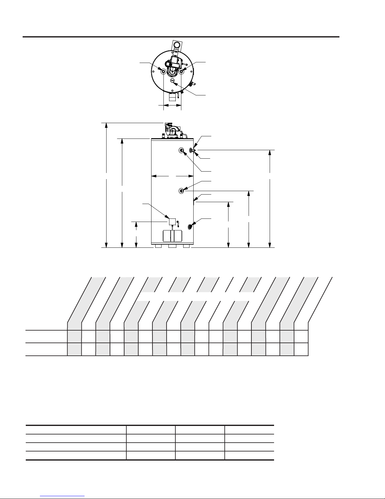
Figure 1: All Models
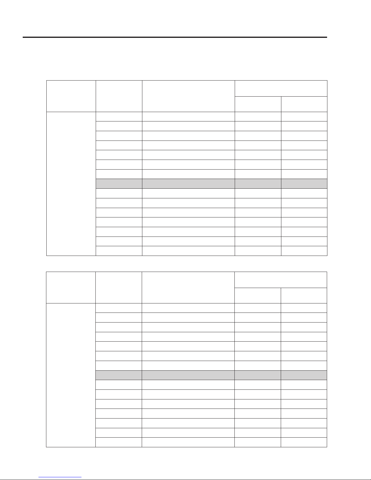
Table 1: Dimensions
o
F rise
DIMENSIONS INCHES (cm)
o
Rated Input
Model
EZ 75-76PDVN-C
EZ 100-76PDVN-C
*Recovery & 1st Hour Delivery values are for gas input with no hydronic load through internal coil
For LP models change suffix "N" to "LP"
Working Pressure: 150 PSI (1034 kPa)
Test Pressure: 300 PSI (2068 kPa)
For natural gas: Manifold pressure = 4" W.C. (1.00 kPa); Inlet pressure range 5-14" W.C. (1.25 - 3.49 kPa)
For propane gas: Manifold pressure = 10" W.C. (1.00 kPa); Inlet pressure range 11-14" W.C. (2.74 - 3.49 kPa)
T&P valve installed
Storage GAL (L)
75 76000 74 132 76.88 67.25 26.00 60.00 28.19 16.00 11.00 34.94 60.00 1.00 1.00 0.50 469
(284) (22.3) (280)*(500)* (195) (171) (66) (152) (72) (41) (28) (89) (152) (213)
100 76000 74 152 76.88 67.25 28.00 60.00 28.19 16.00 11.00 34.94 60.00 1.00 1.00 0.50 572
(379) (22.3) (280)*(575)* (195) (171) (71) (152) (72) (41) (28) (89) (152) (259)
Table 2: PDV-C Coil Performance
Supply Temperature 140°F 120°F 100°F
Return Temperature 120°F 100°F 80°F
Recovery @ 100
BTU/HR (kW)
GAL/HR (L/HR)
Flow Rate (GPM) 3.7 5.0 5.0
1st Hr. Delivery @
100
F rise GAL (L)
A
C
B
Space Heating Capacity (BTU/HR) 31,500 43,000 43,000
*Note: Values were obtained with storage tank setpoint of 180°F
Page 4
E
D
H
G
F
All Bock products meet or exceed current ASHRAE standards.
These products are design certified by UL (Underwriters Laboratories) and meet ANSI Z21.10.3 / CSA
4.3 requirements for operation up to 180°F (82°C).
Approved for use as a direct vent automatic storage water heater.
WARNING: Installation shall be in accordance with all national and/or local codes. In the absense of
local codes, refer to NFPA 54 and/or CSA B149.1.
CAUTION: The recommended maximum hot water temperature setting for normal residential use is
120°F (49°C). Bock recommends a tempering valve or anti-scald valve be installed and used
according to the manufacturer's directions to prevent scalding.
I
Inlet/Outlet
Conn. Dia. (NPT)
Space Heating
Gas Conn. Dia.
Conn. Dia. (NPT)
(NPT)
Shipping Weight
LBS (kg)
SECTION II: GENERAL INFORMATION
WHEN YOU RECEIVE YOUR NEW WATER HEATER
Check the new equipment to see if all components are in good condition. If damage is
observed or parts appear to be missing, contact your wholesaler.
WATER TREATMENT/FILTRATION
In areas where poor water conditions are suspected (i.e. lime, iron, and other minerals), it is
essential that the water be tested and appropriate action taken to prevent damage to the
water heater and ensure the quality of the water.
TEMPERATURE CONTROL
The water heater is equipped with a combination gas valve, ignition control, and thermostat.
For domestic hot water, the proper temperature setting is 120°F (i.e. “WARM” setting on
control). For commercial applications, the maximum approved temperature setting is 180°F
(i.e. “F” setting on control).
A built-in, automatic reset Energy Cut-Off (ECO) is standard on all models. In the event that
the water temperature becomes excessive (195°F), the ECO will shut off all gas to the water
heater. If the ECO switch opens, it will automatically reset (or close) when the water
temperature drops to 120°F or below. The water heater thermostat will automatically reset
following a three minute standby period once the ECO switch closes.
The thermostat is factory set at 120°F. See Figure 21 for temperature and display settings.
If hotter water is required a tempering device or anti-scald device must be installed at the
domestic hot water outlet of the heater or at the point of use. Table 3 details the approximate
relationship of water temperature and time with regard to scald injury. It is important for the
user to understand the necessity of tempering or anti-scald devices when using hotter water in
domestic water heating systems.
䊱
!
CAUTION: Hot water in excess of 120°F can cause scalding!
Bock recommends a tempering valve or anti-scald valve be installed and used according to
the manufacturer’s directions to prevent scalding. Many state and local codes now require
installation of these devices. Point of use temperature may be hotter than the setting on the
water heater thermostat. The tempering valve or anti-scald valve will ensure potable
water temperatures at the desired set point with a higher degree of accuracy.
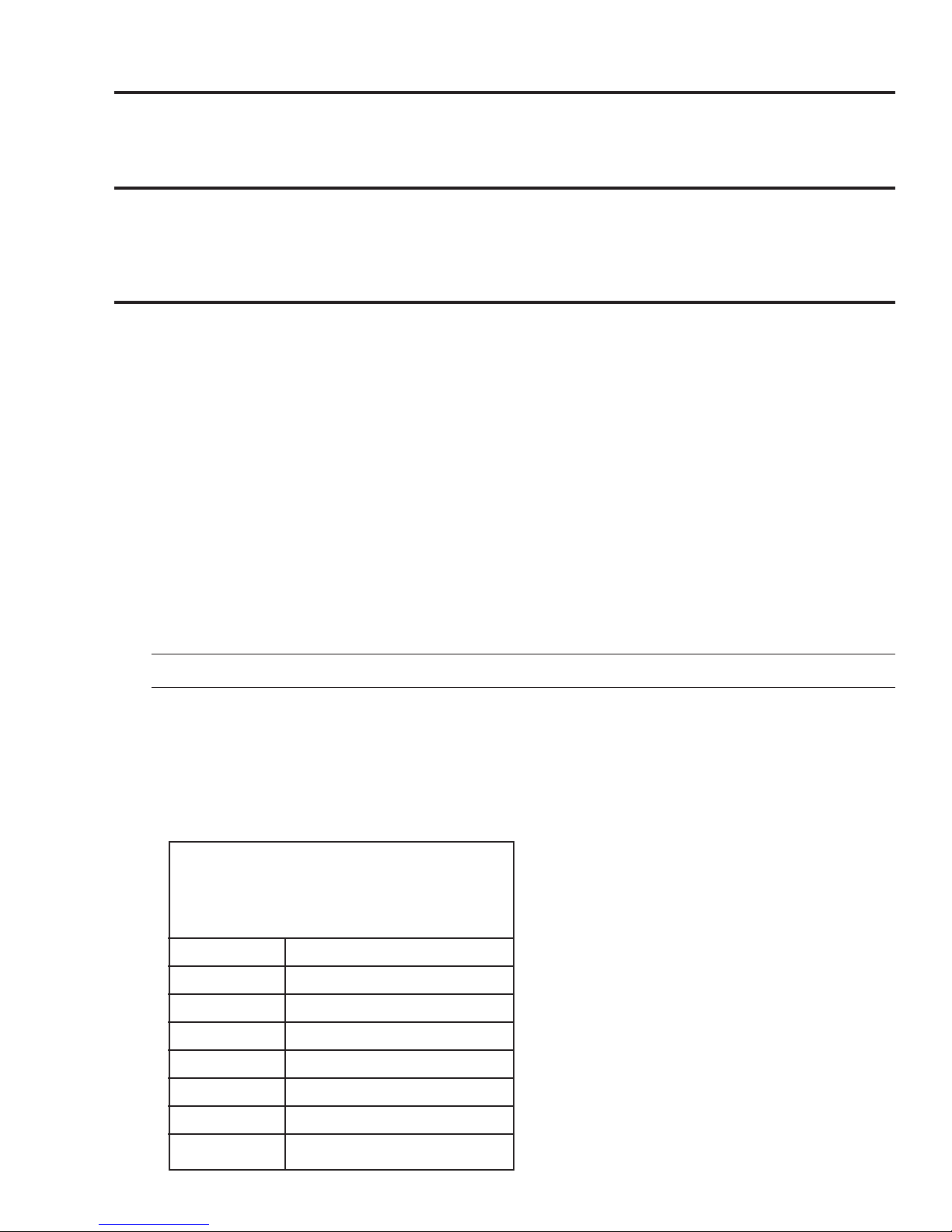
Table 2: Scald Temperature/Time Relationships
APPROXIMATE
TEMPERATURE/TIME
RELATIONSHIPS TO
SCALDING
120°F (49°C) More than 5 minutes
125°F (52°C) 1
1
⁄2 to 2 minutes
130°F (54°C) About 30 seconds
135°F (57°C) About 10 seconds
140°F (60°C) Less than 5 seconds
145°F (63°C) Less than 3 seconds
150°F (66°C) About 1
155°F (68°C) About 1 second
1
⁄2 seconds
Page 5

SECTION II: GENERAL INFORMATION (cont.)
INTERNAL HEAT EXCHANGER COIL
The water heater contains an internal heat exchanger coil which can be used in conjunction
with a radiant (space) heating application. The installation of this water heater, when serving
a space heating application, must be in accordance with local codes. The space heating
application must be designed as a closed loop system. A closed loop system does not introduce
fresh water into the heating loop under normal conditions.
䊱
!
CAUTION
Do not connect the internal coil heat exchanger to an open loop system.
See Section I: Specifications, Table 2 for heat exchanger performance data.
ANODE RODS
The anode rod is used as a sacrificial element within the volume of the storage tank. The
purpose of the magnesium anode rod is to protect the inside of the tank against corrosion.
Anode rods should be inspected twice in the first year and at least yearly once a time interval
for inspection has been developed. Water conditions can influence the consumption rate of
the anode rods. Please see the Maintenance section of this manual for instructions on how to
change the anode rods.
䊱
!
CAUTION
Hydrogen gas is produced in a hot water system served by the heater that has not been
used for a long period of time (2 weeks or more). Hydrogen gas is extremely flammable. To
reduce the risk of injury under these conditions, it is recommended that the hot water faucet
be opened for several minutes at the kitchen sink before using any electrical appliance
connected to the hot water system. When hydrogen is present, there will probably be an
unusual sound such as air escaping through the pipe as the water begins to flow. There
should be no smoking or open flame near the faucet at the time it is open.
TEMPERATURE AND PRESSURE RELIEF VALVE (T&P)
䊱
!
CAUTION
To reduce the risk of excessive pressures and temperatures in this water heater, install
temperature and pressure protective equipment required by local codes and no less than a
combination temperature and pressure relief valve certified by a nationally recognized
testing laboratory that maintains periodic inspection of production of listed equipment or
materials, as meeting the requirements for Relief Valves and Automatic Gas Shutoff Devices
for Hot Water Supply Systems, ANSI Z21.22. This valve must be marked with a maximum set
pressure not to exceed the marked maximum working pressure of the water heater. Install
the valve in an opening provided and marked for this purpose in the water heater, and
orient it or provide tubing so that any discharge from the valve exits only within 6 inches
above, or at any distance below, the structural floor, and does not contact any live
electrical part. The discharge opening must not be blocked or reduced in size under any
circumstances.
Scalding injury and/or water damage can occur from either the manual lifting of the lever
or the normal operation of the T&P valve. If it is not piped to a proper drain. If the valve fails
to flow water or reseat, call your plumber.
The T&P valve is factory installed. A discharge drain tube must be installed (responsibility
of the installer) and shall terminate plain, not threaded, 6 inches above the floor drain.
The drain tube material must be approved for temperatures of 120oF or greater and a
pressure of 150 PSI or greater.
Page 6
䊱
!
CAUTION

SECTION II: GENERAL INFORMATION (cont.)
BACKFLOW PREVENTER (CLOSED SYSTEM)
Some local municipal codes and ordinances require the use of these devices on potable
(domestic) water lines. Where backflow preventers, check valves, or pressure regulating valves
are required, it will be necessary to install a thermal expansion tank (designed for use with
potable water) in order to prevent pressure build up in the water heater and associated piping,
which could cause the T&P valve to discharge. Follow the expansion tank manufacturer’s
recommendations when selecting a tank for your hot water system. The expansion tank
pressure shall equal the water heater system pressure prior to initial warm up.
Note: Working pressure of the water heater is 150 PSI. Do not exceed 150 PSI.
CONDENSATION
In some installations condensation will occur in the venting (exhaust) system. It is important
to not allow condensate to collect around mechanical components and bare metal parts on
the water heater. Therefore, if condensation occurs in the venting system it must be routed to
a proper area for drainage. Horizontal sections of the vent system shall slope downward away
from the water heater a minimum of 1/8" per foot. When downward sloping of the vent
system is not possible or a vertical vent arrangement is used, the condensate drain kit must be
installed. See Section IV: Installation / Vent and Combustion Air Intake / Condensate Drain
Kit for installation details.
HIGH ALTITUDE
Contact Bock Water Heaters for installations at altitudes greater than 2,000 feet above sea level.
SECTION III: PRE-INSTALLATION
LOCATION
This water heater must be located in an area where leakage of the tank, water line
connections, or the temperature and pressure relief valve will not result in damage to
the area adjacent to the water heater or to lower floors of the structure. When such
location cannot be avoided, a suitable drain pan must be installed under the water
heater. The drain pan depth must be suitable for draining and collecting water. The
drain pan can be purchased from your plumbing professional. The drain pan must be
piped to an adequate drain and all drain piping must be at least 0.75” in diameter
and pitched for proper drainage.
DO NOT store or use gasoline or other flammable, combustible, or corrosive vapors
and/or liquids in the vicinity of the water heater or any other appliance.
䊱
!
CAUTION
䊱
!
CAUTION
IF YOU SMELL GAS:
• DO NOT try to light any appliance.
• DO NOT touch any electric switch; do not use any telephone in your building.
• Immediately call your gas supplier from a telephone in another building. Follow your
gas supplier’s instructions.
• If you cannot reach your gas supplier, call the fire department.
DO NOT OPERATE THE APPLIANCE UNTIL THE LEAKAGE IS CORRECTED!
Page 7

SECTION III: PRE-INSTALLATION (cont.)
䊱
!
CAUTION
Do not drop water heater or lay heater down on its side. Move the water heater into
position by sliding or using an appropriately sized hand truck.
䊱
!
CAUTION
If the water heater is installed directly on carpeting, the water heater shall be installed
on a metal or wood panel extending beyond the full width and depth of the water
heater by at least 3 inches (76.2 mm) in any direction or, if the water heater is installed
in an alcove or closet, the entire floor shall be covered by the panel. The panel must be
strong enough to carry the weight of the heater when full of water.
NOTE: Locate the heater so it is not subject to physical damage from moving vehicles or
flooding. Do not locate the water heater in a room where swimming pool chemicals or large
quantities of water softener salt are kept. Installing a water heater in this environment will
result in premature failure of tank and burner components due to corrosion caused by these
elements diffusing into the air.
The water heater can be installed on combustible or non-combustible flooring. Maintain
clearances specified in this manual and in accordance with the National Fuel Gas Code (NFPA
54, ANSI Z223.1) unless otherwise directed by state and local code requirements. Locate the
water heater such that plastic vent pipe lengths and the number of connection fittings are
minimized.
Minimum clearances from combustible construction are:
Table 3: Clearances
SIDES
0 in. (0 cm) 6 in. (15 cm) 24 in. (61 cm) 26 in. (66 cm)
1) Measured from water heater jacket to wall. This clearance accommodates the air intake
boot.
2) Measured from jacket to closet door.
3) Measured from water heater top to ceiling.
This water heater is approved for installation in a closet or alcove with the clearances above.
BACK
1
FRONT
2
TOP
3
COMBUSTION AND VENTILATION AIR
The water heater can be installed to utilize combustion air from either inside or outside the
building. Refer to "Section IV: Installation" for detailed venting specifications. If indoor air is
used for combustion air it is imperative that the room has an adequate air supply. Inadequate
air supplies may lead to unsafe levels of carbon monoxide (CO), condensation of flue gases,
and excessive levels of soot. See NFPA 54 or the discussions of "Unconfined Space" and
"Confined Space" below. In addition, poor ventilation will also result in hot spots around the
heater. Temperatures over 90°F near the water heater generally indicate a lack of ventilation.
Page 8

SECTION III: PRE-INSTALLATION (cont.)
UNCONFINED SPACE
Unconfined space is defined by NFPA 54 as a space with a volume greater than 50 cubic feet
(during typical use) per 1000 BTUH of the total combined input of all fuel burning appliances
in the space. Rooms leading directly to the installation space through doors that cannot be
closed can be considered part of the space. Exception: Buildings with full vapor barriers, tight
doors and windows or air infiltration rates of less than 0.35 air changes per hour will be
considered a confined space and require additional air supplies.
CONFINED SPACE
Confined space is defined by NFPA 54 as a space with a volume less than 50 cubic feet (during
typical use) per 1000 BTUH of the total combined input of all fuel burning appliances in the
space. Buildings or rooms of unusually tight construction are also considered a confined space.
See “Unconfined Space: Exception”.
When installing fuel burning appliances in a confined space, air must be supplied to that
space from either inside or outside of the building as conditions allow.
A. Inside Air Supply: A confined space shall be provided with two permanent openings; one
within 12 inches of the top and one within 12 inches of the bottom of the enclosure. These
openings shall lead directly to room(s) of sufficient volume so that the combined volume of
all the space meets the criteria for unconfined space. Each opening shall have a minimum free
area of 1 square inch per 1000 Btu/hr of the combined total input of all fuel burning
appliances in the space. Each opening shall have an area of not less than 100 square inches or
a minimum dimension of not less than 3 inches.
B. Outside Air Supply: Confined spaces shall be provided with two permanent openings; one
within 12 inches of the top and one within 12 inches of the bottom of the enclosure. These
openings shall communicate directly, or by ducts, with the outdoors or spaces that
communicate with the outdoors.
1.) Leading directly to the outside or through vertical ducts: Each opening shall have a
minimum free area of one square inch per 4000 Btu/hr of total input rating of all equipment
in the enclosure.
2.) Leading to outside through horizontal ducts: Each opening shall have a minimum free
area of one square inch per 2000 Btu/hr of total input rating of all equipment in the enclosure.
Note: All ducts shall have the same cross sectional area as the free area of each opening to
which they connect. The minimum dimensions of all ducts shall not be less than three inches.
Powered combustion air supplies are also commercially available and may be used.
LOUVERS & GRILLES
In calculating the free area of an opening, consideration must be given to the blocking effects
of louvers or grilles protecting the opening. Any screens used must be no finer than1⁄4 inch
mesh. If the free area of a louver or grille is known, this should be used in calculating the size
of opening required. If free area is unknown, it may be assumed that wood louvers will have
20 to 25% free area and metal louvers and grilles will have 60 to 75% free area. Louvers and
grilles should be fixed in the open position or interlocked with the equipment so that they
open automatically during equipment operation.
Page 9

SECTION IV: INSTALLATION
VENT & COMBUSTION AIR INTAKE
䊱
!
DANGER
Failure to properly install the vent and combustion air intake system as outlined in this
manual can result in unsafe operation of the water heater. To avoid the risk of fire,
explosion, or asphyxiation from carbon monoxide, never operate this water heater
unless it is properly vented and has adequate air supply for combustion and dilution of
flue gas. Be sure to inspect the system for proper installation at initial start-up; and at
least annually thereafter. See the Maintenance section for more information.
The water heater venting and combustion air intake can be installed as a power direct
vent system (combustion air from outside the building) or power vent system
(combustion air from inside the building). Vertical or horizontal (side-wall) configurations may be used with a two-pipe or concentric vent termination.
Note: If air from inside the building will be used for combustion air, the requirements in Section III, "Unconfined Space" must be met.
The water heater is supplied with a rubber coupling (with clamps) that connects to the
blower assembly outlet. The air intake piping is preassembled to route dilution air to the
blower assembly and combustion air to the burner chamber. All vent length measurements specified in this manual are in addition to the preassembled piping supplied with
the water heater. Equivalent pipe run lengths shall not be greater than the maximum
lengths (or less than minimums) given in Tables 4 and 5.
Note: DO NOT connect the water heater to an existing vent or chimney. It must
be vented separately from all other appliances.
The following materials are approved for use as the vent and combustion air intake
piping:
• PVC (DWV, ASTM-D2665 or CSA B181.2)
• PVC (Schedule 40, ASTM-D1785 or CSA B137.3)
• PVC (SDR Series, ASTM-D2241 or CSA B137.3)
• CPVC (Schedule 40, ASTM-F441 or CSA B137.3)
• CPVC (SDR Series, ASTM-F442)
• ABS (Schedule 40, DWV, ASTM-D2661 or CSA B181.1)
In Canada, check local codes to ensure that SDR series is approved for use. SDR is
not approved for all installations in Canada.
The following materials are approved for use for the fittings in the vent and combustion
air intake systems:
• PVC (Schedule 40 DWV, ASTM D2665)
• CPVC (Schedule 40, ASTM F438)
• ABS (Schedule 40 DWV, ASTM D2661)
Please contact Bock Water Heaters for questions regarding materials that are not listed
above.
Page 10
SECTION IV: INSTALLATION (cont.)
VENT & COMBUSTION AIR INTAKE (cont.)
Installations in Canada must conform to the requirements of CSA B149 code. Plastic
vent systems must be assembled with pipe, fittings, cements, and primers listed to ULC
S636. Components of this listed system shall not be interchanged with other vent
systems or unlisted pipe/fittings. In Canada, the primer and cement must be of the
same manufacturer as the vent system; do not mix primers and cements from one
manufacturer with a vent system from a different manufacturer. The supplied plastic
pipe/fittings are certified as part of the water heater.
Minimum and Maximum System Lengths
The water heater should be located such that plastic vent pipe lengths and the number of
connection fittings are minimized. Minimum and maximum equivalent pipe lengths for
the vent and combustion air intake systems are given in Tables 4 and 5. Either 3 in. or 4
in. plastic piping may be used. The water heater is provided with fittings that readily
adapt to 3 in. plastic pipe. DO NOT use less than 3 in. diameter plastic pipe and DO NOT
use unequal sizes except as shown to increase from 3 in. to 4 in. diameter at the point of
connection to the water heater.
NOTICE
NOTE: The equivalent straight pipe length of a 90°, 1/4 inch standard bend elbow
and a 45°, 1/8 inch standard bend elbow is 5 feet and 2.5 feet, respectively. The
concentric vent termination is equivalent to 10 feet of straight pipe. DO NOT use
short bend elbows.
NOTE: Elbows used as termination fittings must be included when determining
the total number of elbows.
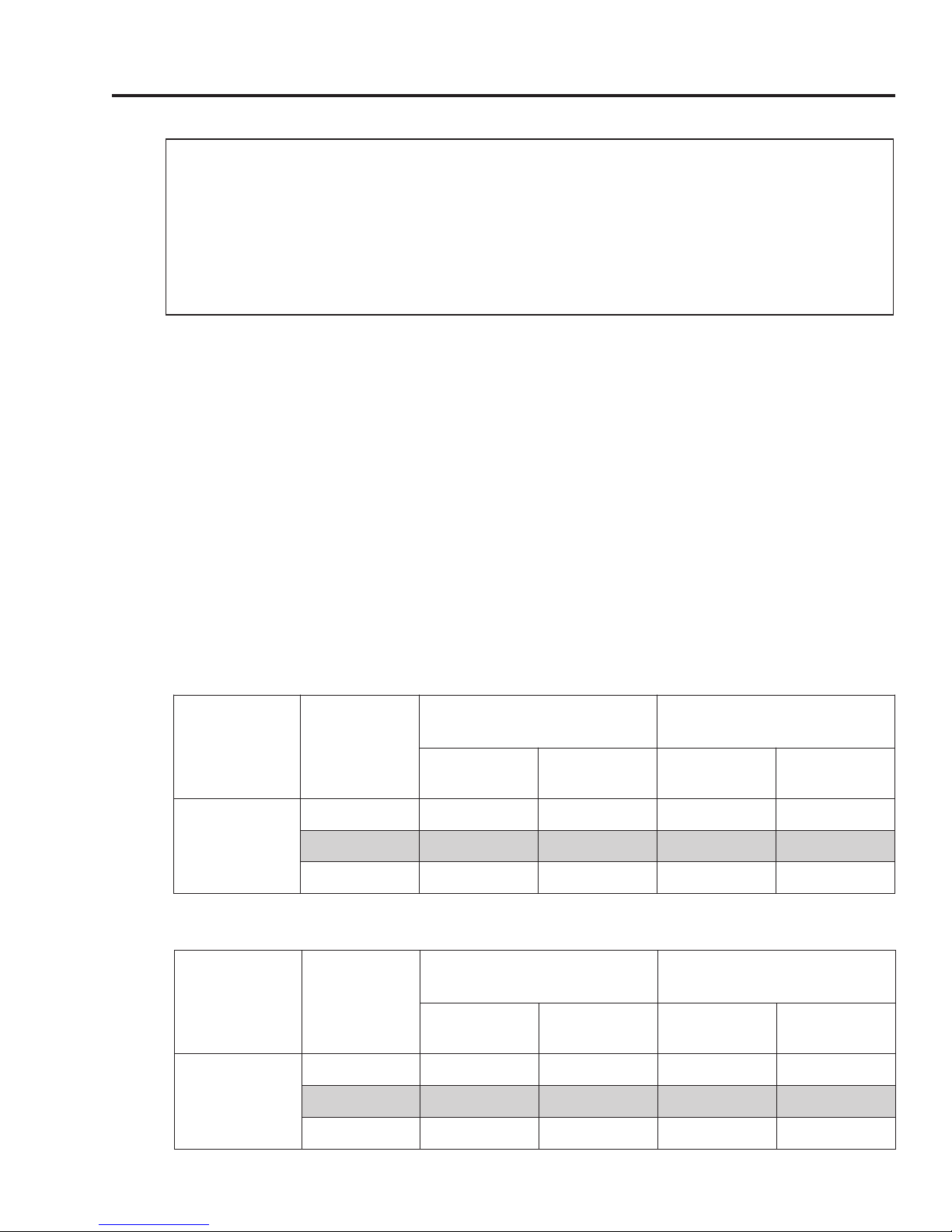
Table 4: Minimum and Maximum Vent and Air Intake Pipe Lengths (Two-Pipe Terminations)
Model(s) Pipe Ø (in)
EZ 75-76PDV,
EZ 100-76PDV
Minimum Equivalent Pipe
Length (per pipe run)
Air Intake
Ft (m)
3 5 (1.52) 12 (3.66) 55 (16.76) 55 (16.76)
4 5 (1.52) 12 (3.66) 85 (25.91) 85 (25.91)
Vent
Ft (m)
Maximum Equivalent Pipe
Length (per pipe run)
Air Intake
Ft (m)
Vent
Ft (m)
Table 5: Minimum and Maximum Vent and Air Intake Pipe Lengths (Concentric Termination)
Model(s) Pipe Ø (in)
Minimum Equivalent Pipe
Length (per pipe run)
Air Intake
Ft (m)
Vent
Ft (m)
Maximum Equivalent Pipe
Length (per pipe run)
Air Intake
Ft (m)
Vent
Ft (m)
EZ 75-76PDV,
EZ 100-76PDV
3 5 (1.52) 12 (3.66) 45 (13.72) 45 (13.72)
4 5 (1.52) 12 (3.66) 75 (22.86) 75 (22.86)
Page 11
SECTION IV: INSTALLATION (cont.)
VENT & COMBUSTION AIR INTAKE (cont.)
For quick reference, Tables 6 and 7 give the maximum allowable length of straight pipe
based on the total number of elbows per pipe run.
Table 6: Maximum Pipe Lengths Quick Reference (Two-Pipe Terminations)
Maximum Equivalent Pipe
Length (per pipe run)
Air Intake
Ft (m)
Model(s) Pipe Ø (in)
3 0 55 (16.76) 55 (16.76)
3 1 50 (15.24) 50 (15.24)
3 2 45 (13.72) 45 (13.72)
3 3 40 (12.19) 40 (12.19)
3 4 35 (10.67) 35 (10.67)
3 5 30 (9.14) 30 (9.14)
3 6 25 (7.62) 25 (7.62)
EZ 75-76PDV,
EZ 100-76PDV
4 0 85 (25.91) 85 (25.91)
4 1 80 (24.38) 80 (24.38)
4 2 75 (22.86) 75 (22.86)
4 3 70 (21.34) 70 (21.34)
4 4 65 (19.81) 65 (19.81)
4 5 60 (18.29) 60 (18.29)
4 6 55 (16.76) 55 (16.76)
# of 90° Elbows per
pipe run
(including termination fittings)
Vent
Ft (m)
Table 7: Maximum Pipe Lengths Quick Reference (Concentric Termination)
Maximum Equivalent Pipe
Length (per pipe run)
Air Intake
Ft (m)
Model(s) Pipe Ø (in)
EZ 75-76PDV,
EZ 100-76PDV
# of 90° Elbows per
pipe run
(including termination fittings)
3 0 45 (13.72) 45 (13.72)
3 1 40 (12.19) 40 (12.19)
3 2 35 (10.67) 35 (10.67)
3 3 30 (9.14) 30 (9.14)
3 4 25 (7.62) 25 (7.62)
3 5 20 (6.10) 20 (6.10)
3 6 15 (4.57) 15 (4.57)
4 0 75 (22.86) 75 (22.86)
4 1 70 (21.34) 70 (21.34)
4 2 65 (19.81) 65 (19.81)
4 3 60 (18.29) 60 (18.29)
4 4 55 (16.76) 55 (16.76)
4 5 50 (15.24) 50 (15.24)
4 6 45 (13.72) 45 (13.72)
Vent
Ft (m)
Page 12
 Loading...