

Bock Water heaters 66W-370, 66W-399, 80W-180, 80W-199, 80W-250 Service Manual
...
Energy Saver
COMMERCIAL 24 VOLT FLUE DAMPER
SERIES WATER HEATER
ATMOSPHERIC GAS WATER HEATERS
SERVICE
MANUAL
Troubleshooting Guide and
Instructions for Service
(To be performed ONLY by
qualied service providers)
Models Covered
by This Manual:
Manual 47324A Save this manual for future reference.
For the Bock Water Heaters
“W” Series Models:
38W-155
75W-(125, 160, 300)
66W-(370, 399)
80W-(180, 199, 250)
80W-(425, 450, 505)
100W-(199, 250, 270, 300)

W-Series
Atmospheric Gas
Table of Contents
Service
Page Procedure
Introduction 3 - - Tools Required for Service 3 - - Sequence of Operation 4 - - Troubleshooting 5 - - Thermostat Circuit Testing 6 24-I
Pilot Operation Testing 8 24-II
Main Burner Operation Testing 10 24-III
Main Burner and Pilot Removal and Inspection 12 24-IV
Flue Baffle Removal and Inspection 14 24-V
Anode Removal and Inspection 15 24-VI
Generic Parts List 16 - - Glossary of Terms/Notes 19 - - -
2

W-Series
It is intended for this manual to be used by qualied service personal for the primary purpose of
troubleshooting, analysis, and repair of the Bock 24 Volt Flue Damper W-Series Water Heater.
Understanding the “Sequence of Operation” section of this manual will contribute greatly to
troubleshooting this product.
Troubleshooting begins simply by resetting the water heater and observing the lighting sequence
to determine failure mode. This step-by-step procedure beginning on Page 5 will direct the service
provider to a series of test procedures to determine the root cause of failure.
Contact Technical Support immediately if diagnosis is not determined using the methods described
in this service manual.
Tools Required for Service
Manometer: Two types available, a liquid “U” tube type or a digital (magna-helic) type.
This device is used to measure gas and/or air pressures and vacuum.
Multi-Meter: A digital type is strongly recommended. This device is used to measure
electrical values. The meter you select must have the capability to
measure volts AC, volts DC, amps, micro amps and ohms.
Introduction
Thermometer: Used to measure water temperature. An accurate thermometer is
recommended.
Water Pressure Gauge: Used to measure water supply pressure. Also used to determine tank
pressure by adapting to the drain valve of the heater.
Jumper Leads: A length of wire (12” min.) with alligator clip at both ends.
Various Hand Tools: Pipe wrench, channel locks, open-end wrench set, 12” crescent wrench,
allen wrench set, torx bit set, screw drivers (common and phillips), long
reach (12”) magnetic tip phillips head screw driver #2 tip, ¼” nut driver,
pliers (common and needle nose), socket set including a 1 - 1/16” deep
well socket, wire cutters, wire strippers, wire crimpers, torpedo level, small
shop vac, step ladder, and ashlight.
3
W-Series
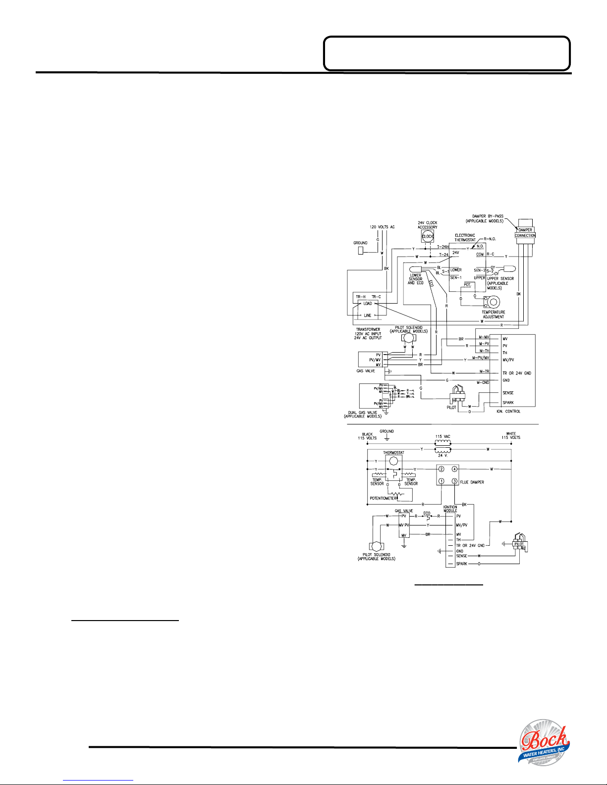
WIRING DIAGRAM
1. Thermostat calls for heat. The relay closes on the thermostat board, sending 24 volts from the
“COM” terminal of the thermostat board to the ue damper.
2. Flue damper begins to rotate open. Once damper is full open, 24 volts is allowed to continue through
damper to the “TH” terminal of ignition module.
3. LED on ignition module illuminates.
4. Trial for ignition (90 second trials, 3 trials with 30 second pause between trials)
Ignition module simultaneously sends:
1. 24 volts from “MV/PV” terminal, to “MV/PV”
terminal of gas valve (common terminal).
2. 24 volts from “PV” terminal, through the ECO
located in the lower thermister, to “PV” terminal of
gas valve to establish gas ow at pilot.
3. Low current high voltage from “spark” terminal,
to generate spark at the pilot and ignite pilot gas
ow.
Sequence of Operation
4. Pilot ame proving signal (measured in micro
amps) from the “sense” terminal, to prove pilot
ame.
5. Once pilot ame is proven, spark will stop.
6. Once spark stops, 24 volts is sent from “MV” terminal on
module, to “MV” terminal on gas valve to establish main
burner gas ow. Main burners ignite from the pilot ame.
The ignition module constantly monitors pilot ame. If the
pilot ame is lost, pilot and main burner are shut down.
After a 30 second purge period, module will attempt to
re-light pilot beginning at sequence 4 above.
7. Main burner res until the thermostat is satised. The
relay on the thermostat board opens, interrupting 24 volts
through the damper and ignition module. Pilot and main
burner are turned off.
8. Flue damper rotates to the closed position.
LOCKOUT CONDITION
Ignition module will “lockout” if the pilot cannot be lit after 3 ignition trials. The ignition module indicates a
lockout condition by the continuing ash of the LED located on the module.
Lockout reset is accomplished by interrupting 120 VAC to the unit for at least 5 seconds.
4
W-Series
1
1A
2
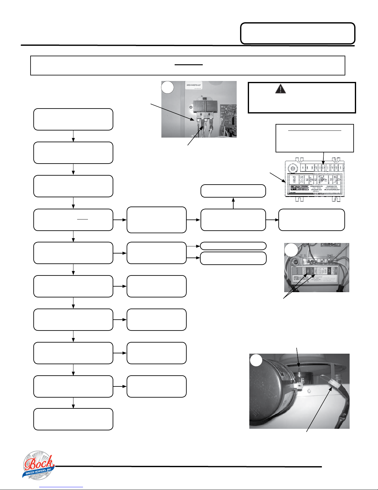
Use Caution Not to Damage Connectors When Making Voltage Measurements or Jumping Terminals.
Rear Terminals
Verify primary and secondary
voltage at the transformer.
(see photo 1)
If LED on ignition module is
ashing, reset water heater by turning
“OFF” power. Wait 5 seconds and turn
power back “on”.
Rotate thermostat dial to the
highest setting.
(120 VAC)
primary
CAUTION
Forward Terminals
primary
(24 VAC)
Troubleshooting
120 Volt Exposure. Use Caution
Ignition Module
See “thermostat testing.”
(page 6)
DANGER
to Avoid Personal Injury
Ignition Module LED Status
OFF = No power to module
ON = Module has power
Flashing = Module is in lock-out
Does damper vane move to the full
Does LED light on ignition module
open position?
Y
illuminate?
Y
Is there pilot ame?
Y
Does main burner operate?
Y
Does burner continue until
thermostat set point is reached?
Y
Does ue damper rotate to the
closed position?
Y
Remove damper from
N
N
N
N
N
N
heater and jump black
& yellow wires of heater
harness.
(see photo 2)
Is there 24 VAC between
terminals “TR” & “TH” of the
ignition module?
(see photo 1A)
See “pilot will not light.”
(page 8)
See “pilot lights,
no ame signal.”
(page 9)
See “main burner
short cycle.”
(page 11)
Check for debris limiting
damper rotation. If no
debris, replace damper.
N
Does LED light on
ignition module
illuminate?
Y
N
Replace ignition module
Check damper
harness connection
Check for 24 VAC
Y
across terminals
“TR” & “TH”
Damper vane shown in open position. If damper
is closed, disconnect from harness and
REMOVE damper from water heater.
Check for debris limiting
damper rotation. If no
debris, replace damper.
System okay.
Harness shown disconnected from damper
with BLACK and YELLOW wires jumped.
5
W-Series
3
4
5
7
6
8
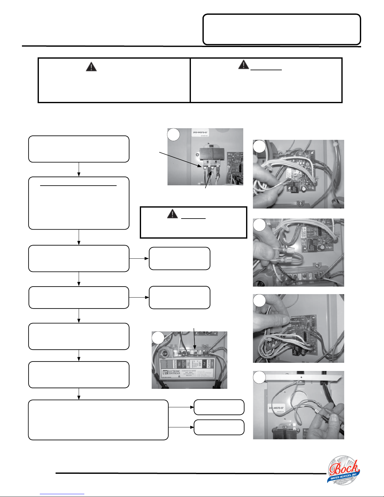
Service Procedure 24-I
Thermostat Circuit Testing
DANGER
120 Volt Exposure. To avoid personal injury,
use caution while performing this procedure.
Be careful when making voltage
measurements or jumping terminals
not to damage or deform connectors or
CAUTION
connector pins.
This procedure assumes the ue damper is in working order. Be sure damper opens under its own power when the
thermostat circuit is bypassed. Damper must be open or removed during this test. Do not force damper open using your
hands or tools.
With power on to water heater, verify
primary and secondary voltage at
the transformer.
(see photo 3)
THERMOSTAT CIRCUIT BYPASS
Turn power “OFF” to water heater and
locate thermostat board inside control box
of water heater. Disconnect YELLOW wires
from the thermostat board at location
“N.O.” & “COM.” Use a jumper to connect
these two wires together.
(see photos 4 & 5)
Rear
Terminals
Primary
(120 VAC)
Forward Terminals
Secondary
(24 VAC)
DANGER
Do not leave thermostat jumper in
place for normal operations.
Turn power on to water heater.
Does LED on ignition module illuminate?
Does pilot and main burner operate?
Remove jumper and reconnect wires to
thermostat board. Wires are identied for
Disconnect ORANGE potentiometer (temp
adjustment dial) wires from thermostat
Check potentiometer for proper resistance values of:
Greater than 4800 Ohms with dial at minimum setting.
Less than 50 Ohms with dial at maximum setting.
(see photo 6)
Y
Y
Turn power “OFF.”
proper connection to board.
board. (see photo 7)
(see photo 8)
Are readings correct?
N
N
Verify transformer voltage.
(see photo 3)
See pilot operation testing.
(page 8)
LED Location
N
Y
Replace potentiometer.
Check thermisters.
(see page 7)
6
 Loading...