


Instruction Manual
plus
TCU 40/80
W95900011
Revision F
June, 2004
Temperature Control Unit
Single Channel
301 Ballardvale Street Wilmington, MA 01887
Telephone: (978) 658-5410 Telex: 710-347-7672 Fax: (978) 658-7969
BOC EDWARDS


TABLE OF CONTENTS
SECTION TITLE PAGE
1 PREFACE ………………………………………………………………………………………….. 1
1.1 SAFETY CONSIDERATIONS …………………………………………………………………. 1
2 TCU 40/80
2.1 SCOPE OF THE MANUAL …………………………………………………………………….. 3
2.2 DESCRIPTION FOR THE TCU 40/80
2.3 LOCKOUT PROCEDURE ……………………………………………………………………… 3
2.4 SAFETY FEATURES ……………………………………………………………………………4
3 QUICK START PROCEDURE ……………………………………………………………………. 5
3.1 POWER UP ………………………………………………………………………………….….. 5
3.2 SETPOINT VERIFICATION …………………………………………………………………… 5
4 PRODUCT DESCRIPTION ……………………………………………………………….………. 6
4.1 REFRIGERATION AND COOLANT CIRCUITS …………………………………………….. 6
4.2 REFRIGERATION ……………………………………………………………………………… 9
4.2.1 IF COOLING IS REQUIRED ………………………………………………………………. 9
4.2.2 IF COOLING IS NOT REQUIRED ………………………………………………………….9
4.3 COOLANT CIRCUIT …………………………………………………………………………… 10
4.4 TEMPERATURE MONITORING ……………………………………………………………… 10
4.5 FRONT PANEL …………………………………………………………………………………. 10
4.6 REAR PANEL ……………………………………………………………………………………12
4.7 SPECIFICATIONS ……………………………………………………………………………… 13
4.8 DIMENSIONS …………………………………………………………………………………... 14
5 INSTALLATION ……………………………………………………………………………………15
5.1 RECEIVING AND UNPACKING ……………………………………………………………… 15
5.2 LOCATION ………………………………………………………………………………………15
5.2.1 SECURING THE UNIT ……………………………………………………………………….15
5.2.2 INSTALLING THE SECONDARY CONTAINMENT RECEPTACLE ……………………. 15
5.2.3 FLOOR LEVELERS …………………………………………………………………………. 15
5.3 STACKING ……………………………………………………………………………………… 16
5.3.1 TIE-BOLTS …………………………………………………………………………………...16
5.4 FACILITIES ……………………………………………………………………………………...16
5.4.1 50 Hz Installations………………………………………………………………………………16
5.4.2 WATER AND COOLANT CONNECTIONS ………………………………………………...16
5.4.3 WATER ………………………………………………………………………………………..18
5.4.4 COOLANT …………………………………………………………………………………….18
5.4.5 REMOTE CONNECTIONS ………………………………………………………………….. 18
6 OPERATION ……………………………………………………………………………………….. 19
6.1 PREPARATION ………………………………………………………………………..………...19
6.2 POWERING UP THE TCU 40/80 plus …………………………………………………………. 19
6.3 CHANGING THE SETPOINT VALUE (SV1) ………………………………………………….20
6.4 TEMPERATURE CONTROLLER PID SETTINGS …………………………………..……….. 20
6.5 REMOTE SET POINT ………………………………………………………………………….. 20
6.6 FLOW RATE ADJUSTMENT ………………………………………………………………….. 21
plus
…………………………………………………………………………………….. 3
plus
…………………………………………….………. 3
TCU 40/80 plus Temperature Control Unit i

7 MAINTENANCE ……………………………………………………………………………………22
7.1 HAZARD WARNINGS ………………………………………………………………………….22
7.2 HAZARDS ………………………………………………………………………………………. 24
7.3 FILLING THE RESERVOIR …………………………………………………………..……….. 24
7.4 DRAINING/BLEEDING THE COOLANT RESERVOIR ……………………………………... 25
7.5 TEMPERATURE PROBE CALIBRATION ……………………………………………………. 25
7.6 PREVENTIVE MAINTENANCE SCHEDULE ……………………………………………….. 25
7.7 SEMI-ANNUAL PREVENTATIVE MAINTENANCE ………………………………………... 26
7.7.1 REQUIRED EQUIPMENT …………………………………………………………………... 26
7.7.2 PREPARATION ……………………………………………………………………………... 26
7.7.3 VERIFY SYSTEM STATUS ………………………………………………………………… 26
7.7.4 REFRIGERATION LEAK CHECK …………………………………………………………. 26
7.7.5 FLUORINATE LEAK CHECK ……………………………………………………………… 26
7.7.6 WATER LEAK CHECK …………………………………………………………………….. 26
7.7.7 INSULATION REPAIR ……………………………………………………………………... 27
7.7.8 LAMP CHECK/REPLACEMENT …………………………………………………………... 27
7.8 ANNUAL PREVENTATIVE MAINTENANCE ………………………………………………..28
7.8.1 REQUIRED EQUIPMENT …………………………………………………………………... 28
7.8.2 REQUIRED SUPPLIES ……………………………………………………………………… 28
7.8.3 SOLENOID VALVE COIL REPLACEMENT ……………………………………………… 28
7.8.4 SYSTEM CHECK ……………………………………………………………………………. 30
7.9 PREVENTATIVE MAINTENANCE CHECKLIST …………………………………………….39
8 TROUBLESHOOTING …………………………………………………………………………….. 40
9 ACCESSORIES AND SPARE PARTS ……………………………………………………………..54
10 OPTIONS …………………………………………………………………………………………… 55
10.1 LON WORKS …………………………………………………………………………………… 55
10.1.1 REFERENCE ………………………………………………………………………………… 55
10.1.2 OVERALL DESCRIPTION …………………………………………………………………. 55
10.1.3 REQUIREMENTS …………………………………………………………………………… 56
10.1.4 INTERFACES ………………………………………………………………………………... 59
10.2 RS232 TEL ………………………………………………………………………………………. 71
10.2.1 BLOCK DIAGRAM …………………………………………………………………………. 71
10.2.2 OPERATION MODE AND CONTENTS OF FUNCTION …………………………………. 71
10.2.3 DESCRIPTION OF EXTERNAL CONTROL AND MONITORING SIGNALS …………... 73
10.3 RS485 SERIAL COMMUNICATION ………………………………………………………….. 92
10.3.1 MODIFIED ELECTRICAL CONTROLS DRAWER …………………………………………...92
10.3.2 RS485 MODICON MODBUS PROTOCOL ………………………………………………… 92
10.3.3 INSTALLATION AND SE-UP OF RS485 INTERFACE BOX ASSEMBLY ……………... 93
10.3.4 RS485 MODICON MODBUS PROTOCOL SPECIFICATION FOR TCU 40/80 ………….. 102
10.3.5 RS485 4X MEMORY MAP FOR TCU 40/80 HEAT EXCHANGER ………………………. 103
10.3.6 RS485 TCU 40/80 MESSAGE EXAMPLE ………………………………………………….. 104
APPENDIX ……………………………………………………………………………………………………105
RETURN OF BOC EDWARDS EQUIPMENT – PROCEDURE (FORM HS1) ………….…………….. 106
RETURN OF BOC EDWARDS EQUIPMENT – DECLARATION (FORM HS2) ……………………...107
LEGAL NOTICES, LIMITATIONS AND DISCLAIMERS …………………………………………….. 108
MSDS (MATERIAL SAFETY DATA SHEET) – “SUVA” HP62 ……………………………………….109
ii TCU 40/80 plus Temperature Control Unit

ILLUSTRATIONS
FIGURE TITLE PAGE
FIGURE 1 – REFRIGERATION AND COOLANT COMPONENTS …………………………………… 6
FIGURE 2 – REFRIGERATION AND COOLANT COMPONENTS …………………………………… 7
FIGURE 3 – REFRIGERATION AND COOLANT CIRCUITS …………………………………………. 9
FIGURE 4 – FRONT PANEL ……………………………………………………………………………… 10
FIGURE 5 – ELECTRICAL REAR PANEL ……………………………………………………………… 12
FIGURE 6 – TCU DIMENSIONS …………………………………………………………………………. 14
FIGURE 7 – TCU DIMENSIONS …………………………………………………………………………. 14
FIGURE 8 – STACKED TCU 40/80
FIGURE 9 – SYSTEM REAR VIEW ……………………………………………………………………… 17
FIGURE 10 – WATER CONNECTIONS …………………………………………………………………. 18
FIGURE 11 – TEMPERATURE CONTROLLER ………………………………………………………… 20
FIGURE 12 – LAMP REPLACEMENT …………………………………………………………………… 27
FIGURE 13 – SOLENOID COIL REPLACEMENT ……………………………………………………… 29
FIGURE 14 – ELECTRICAL DRAWER ANALOG………………………………………………………. 49
FIGURE 15 – ELECTRICAL DRAWER SCHEMATIC …………………………………………………. 51
FIGURE 16 – REMOTE INTERFACE ……………………………………………………………………. 53
FIGURE 17 – OVERALL LTCI ARCHITECTURE ……………………………………………………… 55
FIGURE 18 – LTCI PHYSICAL LAYOUT ………………………………………………………………. 56
FIGURE 19 – ELECTRICAL REAR PANEL …………………………………………………………….. 65
FIGURE 20 – ELECTRICAL DRAWER LONWORKS……………………………………………………. 66
FIGURE 21 – ELECTRICAL DRAWER SCHEMATIC …………………………………………………….68
FIGURE 22 – REMOTE INTERFACE ……………………………………………………………………… 70
FIGURE 23 – BLOCK DIAGRAM ………………………………………………………………………….. 71
FIGURE 24 – “RUN”/”STOP” SIGNAL ……………………………………………………………………..73
FIGURE 25 – CONTROL SIGNAL STATE …………………………………………………………………74
FIGURE 26 – PIN ASSIGNMENT FOR TCU-TEL CABLE ……………………………………………….. 75
FIGURE 27 – ELECTRICAL REAR PANEL ………………………………………………………………..84
FIGURE 28 – RS232 ELECTRICAL DRAWER ……………………………………………………………. 86
FIGURE 29 – RS232 POWER DISTRIBUTION SCHEMATIC …………………………………………….88
FIGURE 30 – ASSEMBLY CABLE TCU HOST COMMUNICATION …………………………………… 90
FIGURE 31 – ASSEMBLY CABLE TCU RS232 COMMUNICATION ……………………………………91
FIGURE 32 – RS485 ELECTRICAL DRAWER COMPONENT LAYOUT ………………………………..94
FIGURE 33 – RS485 ELECTRICAL DRAWER SCHEMATIC ……………………………………………. 96
FIGURE 34 – RS485 INTERFACE BOX – PHYSICAL DIMENSIONS …………………………………... 98
FIGURE 35 – RS485 INTERFACE BOX WITH TOP COVER REMOVED ………………………………. 99
FIGURE 36 – MICROPROCESSOR PCA – JP7 PIN DESCRIPTION AND FUNCTION …………………99
plus
SYSTEMS ……………………………………………………… 16
TCU 40/80 plus Temperature Control Unit iii

ILLUSTRATIONS (continued) ….
FIGURE TITLE PAGE
TABLE 1 – SAFETY FEATURES ………………………………………………………………………….. 4
TABLE 2 – FRONT PANEL INDICATORS ……………………………………………………………… 5
TABLE 3 – REFRIGERATION AND COOLANT COMPONENTS ………………………………………..8
TABLE 4 – FRONT PANEL CONTROLS ………………………………………………………………….. 11
TABLE 5 – FRONT PANEL LED INDICATORS ………………………………………………………….. 11
TABLE 6 – TEMPERATURE CONTROLLER …………………………………………………………… 11
TABLE 7 – DESCRIPTION OF REAR PANEL COMPONENTS AND INDICATORS ………………… 12
TABLE 8 – FRONT PANEL POWER UP INDICATOR CONDITIONS ………………………………… 19
TABLE 9 – ELECTRICAL HAZARDS CLASSIFICATIONS …………………………………………… 24
TABLE 10 – PREVENTIVE MAINTENANCE SCHEDULE ……………………………………………….25
TABLE 11 – FAULTS IDENTIFIED BY FRONT PANEL LAMPS ……………………………………….. 40
TABLE 12 – FAULTS INDICATED BY THE FRONT PANEL LED INDICATORS …………………….. 42
TABLE 13 – FAULTS IDENTIFIED BY REAR PANEL INDICATORS …………………………………..46
TABLE 14 – MISCELLANEOUS FAULT CONDITIONS ………………………………………………….47
TABLE 15 – ACCESSORIES ………………………………………………………………………………...54
TABLE 16 – ANALOG TEMPERTURE SIGNAL CHARACTERISTICS ………………………………... 58
TABLE 17 – LTCI NETWORK VARIABLES ……………………………………………………………… 61
TABLE 18 – DEFINITIONS OF NVOSTATUS NETWORK VARIABLE ……………………….……….. 62
TABLE 19 – DESCRIPTION OF REAR PANEL COMPONENTS AND INDICATORS ………………….65
TABLE 20 – AVAILABLE FUNCTIONS …………………………………………………………………... 72
TABLE 21 – PIN ASSIGNMENTS AT THE TCU HOST CONNECTION ……………………….……….. 75
TABLE 22 – CONTROL CODE ……………………………………………………………………………...76
TABLE 23 – HEADER CODE ………………………………………………………………………………. 76
TABLE 24 – DESCRIPTION OF REAR PANEL COMPONENTS AND INDICATORS ………………….85
TABLE 25 – TCU 40/80 “J72J1” CONNECTOR MODIFIED FOR RS485 ……………………….………..100
TABLE 26 – HOST RS485 COMMUNICATION CONNECTOR …………………………………………..101
iv TCU 40/80 plus Temperature Control Unit

1. Preface
1.1 Safety Considerations
Many safety features have been designed into the TCU 40/80 plus to protect the operator and the
equipment. The following symbols are used in this manual to indicate the various safety
conditions.
General Alert
Electric Shock
General Alert symbol denotes the potential of
personal hazards or equipment failure.
Warnings are given when failure to observe the
instruction could result in injury or death to
persons.
Cautions are given where failure to observe the
instruction could result in damage to the
equipment, associated equipment and process.
Statement on avoiding the hazard.
Electric Shock symbol denotes the presence of
high voltage or current. It calls attention to the
procedure, practice, or the like, which if not done
correctly or adhered to could result in injury or
death.
Statement on avoiding the hazard.
Eye Protection
Toxic Gases
Eye Protection symbol denotes a hazard which
could cause injury or irritation to the eyes.
Statement on avoiding the hazard.
Toxic Gases symbol denotes a personal hazard.
It calls attention to the procedure, practice, or the
like, which if not done correctly or adhered to
could result in injury or death.
Statement on avoiding the hazard.
TCU 40/80 Temperature Control Unit 1

Hot Surfaces
Hot Surfaces symbol denotes a hazard which
could cause injury or burns.
Statement on avoiding the hazard.
Hand
Hand Protection symbol denotes a hazard which
could cause injury or burns
Protection
Statement on avoiding the hazard.
High Pressure
High Pressure symbol denotes a personal hazard
or equipment failure. It calls attention to the
procedure, practice, or the like, which if not done
correctly or adhered to could result in equipment
damage, injury or death.
Statement on avoiding the hazard.
Extreme
Extreme Temperature symbol denotes a hazard
which could cause injury or burns.
Temperatur
e
Statement on avoiding the hazard.
2 TCU 40/80 plus Temperature Control Unit

2. TCU 40/80 plus
2.1 Scope of the Manual
This manual provides information on the installation, start-up and operation of Edwards High Vacuum
Model 40/80 Temperature Control Unit (TCU 40/80
The Quick Start Procedure on page 5 is a step by step guide for the start up and use of an installed,
working system.
Installation, starting on page 17, provides instructions and information for installing the system. The
installer must have sufficient technical understanding of electrical and mechanical systems to properly use
this information.
Operation, starting on page 21, provides more complete instructions on the preparation and use of the
system.
2.2 Description of the TCU 40/80 plus
The TCU 40/80
remote heat loads.
From distances up to 50 feet, the TCU 40/80
equipment. The coolant circulates through the TCU 40/80
then is transferred to the process equipment, and returns in a closed loop. The TCU 40/80
supply coolant at a temperature between -40 °C and +80 °C, selectable in 0.1 °C increments, with a
tolerance of ±1.0 °C.
2.3 Lockout Procedure
To prevent accidental or unauthorized starting of the TCU 40/80
power cord from the receptacle and install an appropriate lock-out device (Hubbell Small PlugoutÔ or
equivalent) on the end of the power cord.
plus is a single-channel temperature control unit engineered for temperature control of
plus).
plus can cool the heat load generated by the process
plus, where it is cooled or heated as required,
plus maintains
plus during maintenance, disconnect the
TCU 40/80 Temperature Control Unit 3

2.4 Safety Features
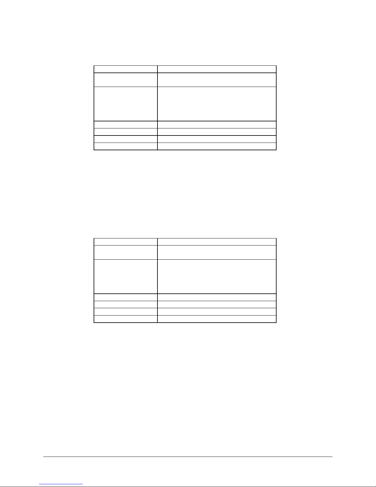
The safety features listed in Table are designed into the TCU 40/80
Component
EMERGENCY OFF
button (EMO)
Remote EMERGENCY
OFF
Drawer safety switch (LS1) Upon opening the drawer, shuts off power to major system
Pressure switch (PS1) Protects the refrigeration system against high discharge
plus.
Table 1 - Safety Features
Ref. Des. *
(PB1) Shuts off power to major system components.
(J72J2) Remote shut off of power to major system components.
components.
pressure. Interrupts operation at 300 psig.
Function
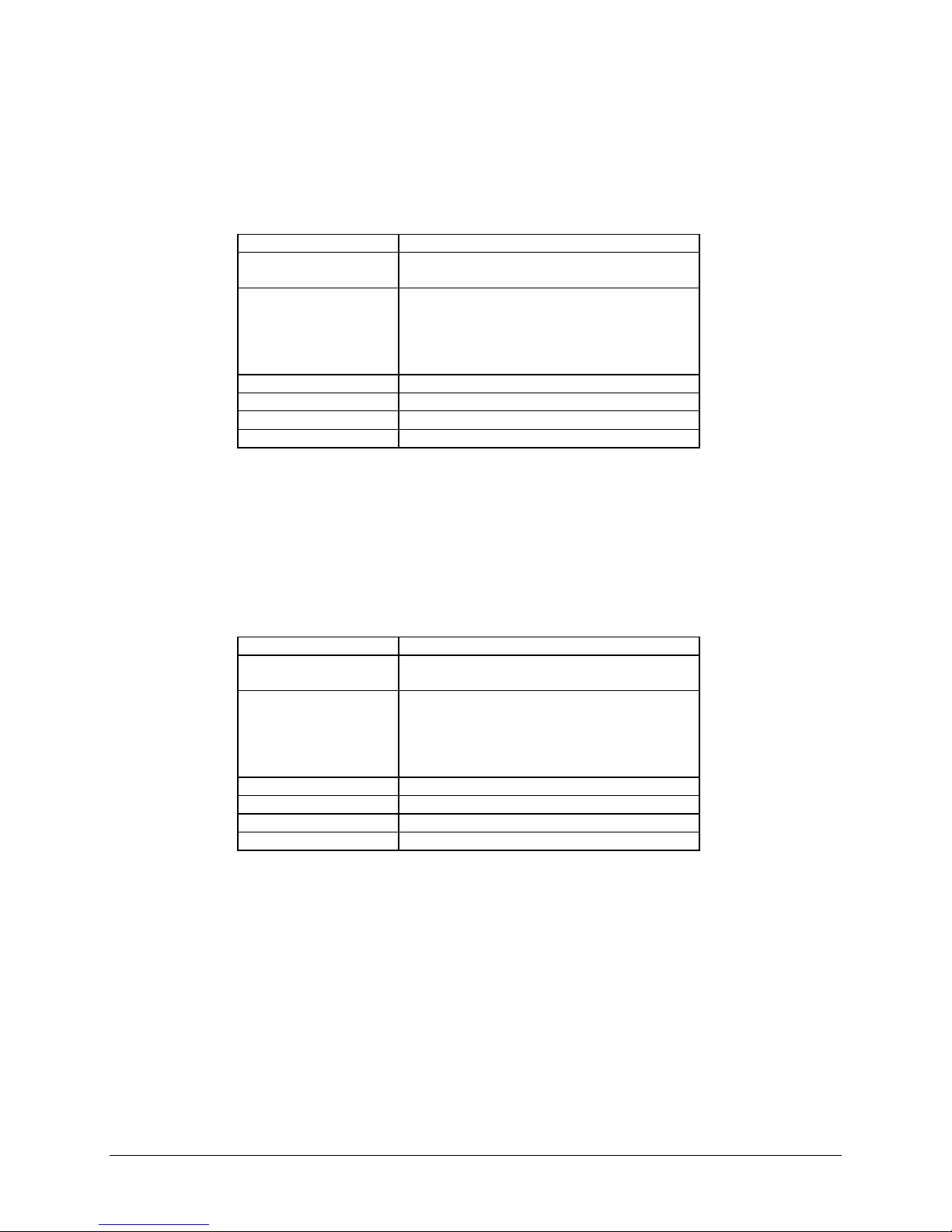
Condenser pressure relief
valve
Reservoir pressure relief
valve
Temperature switch (TS1)
Coolant flow switch (FS1) Protects the process equipment from inadequate coolant
Coolant float switch (LLS1) Protects against low level in the coolant reservoir by
Coolant float switch (LLS3) Protects against overfill of the coolant reservoir. Indication
Thermal overload (K3) Protects the pump motor from excess current.
Surge suppression VR1-4
Line phase monitor PMR1 Protects the equipment against incorrect wiring of the
(W2) Vents refrigerant to the atmosphere above 350 psig. Fail
safe for PS1, works even if there is no power applied to the
system.
(W1) Protects the reservoir from over-pressure.
Protects the process fluid from exceeding 99 °C
flow rates.
stopping the equipment.
on front and rear panels.
Protects the TCU 40/80
power line transients.
supply phases and low voltage burn-out.
plus against voltage surges and
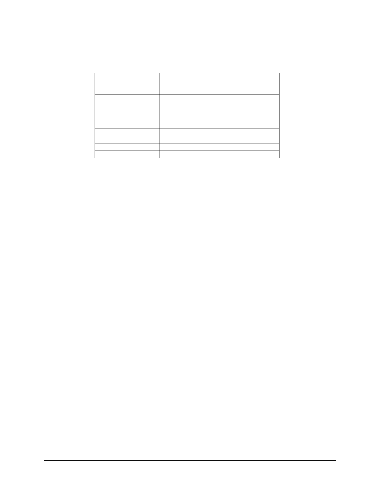
Current sensor CSR1 Protects the compressor against abnormal conditions.
Secondary containment Captures fluids (internal to the TCU) in the event of a leak.
* See Figure 3 on page 10
4 TCU 40/80 plus Temperature Control Unit

3. Quick Start Procedure
This Quick Start procedure is for easy start
up and operation of an installed
working TCU 40/80 plus. If your TCU 40/80
plus is not installed, go to Installation,
Section 5 on page 17. Detailed operating
instructions are in Operation, Section 6 on
page 21. If at any time an alarm occurs,
press STOP and correct the fault indicated
by the display as directed in the
Troubleshooting Guide, Section 8 on page
43. Press RESET and START to continue
operation.
3.1 Power Up
Before applying power, verify that
all water and coolant lines are
connected to the system. The
handles on both coolant line valves
should be in the open position. For
the location of these connections,
refer to Figure 9 on page 19.
To power up the TCU 40/80 plus:
1. READY light should be on. If
the ready light is not on see
Powering Up the TCU 40/80
plus on page 21.
2. Press RESET. Verify that
front panel indicators are as
shown in the Reset column of
Table 2 on this page.
3. Press START. Verify that
front panel indicators are as
shown in the Start Condition
column of Table on this
page.
If in steps two or three any front
panel indicators do not match, refer
to the Troubleshooting Guide
Section 8 on page 43 for corrective
action.
4. Verify that the coolant
pressure gauge (located on the
front access panel) reads less
than 100 psig.
and fully
Table 2 - Front Panel Indicators
Indicator Reset
Condition
Power On Green Green
Reset White White
Facility Power Off Green
Facility Water Green Green
Circuit Breakers Green Green
Compressor Off Green
Temperature Green Green
Flow Off Green
Normal Level Green Green
Low Level Off Off
Remote RTD
(Optional)
Green
(if used)
Start
Condition
Green
(if used)
3.2 Setpoint Verification
Verify that the manual mode
setpoint value (SV1) displayed on
the temperature control is the value
desired. To change the Setpoint
value see Changing the Setpoint
Value (SV1) Section 6.3 on page
22.
Do not to exceed the normal
operating parameters. The system
is designed to operate from -40 °C
to +80 °C.
TCU 40/80 Temperature Control Unit 5

TCU 40/80 Temperature Control Unit 6
4. Product Description
4.1 Refrigeration and Coolant Circuits
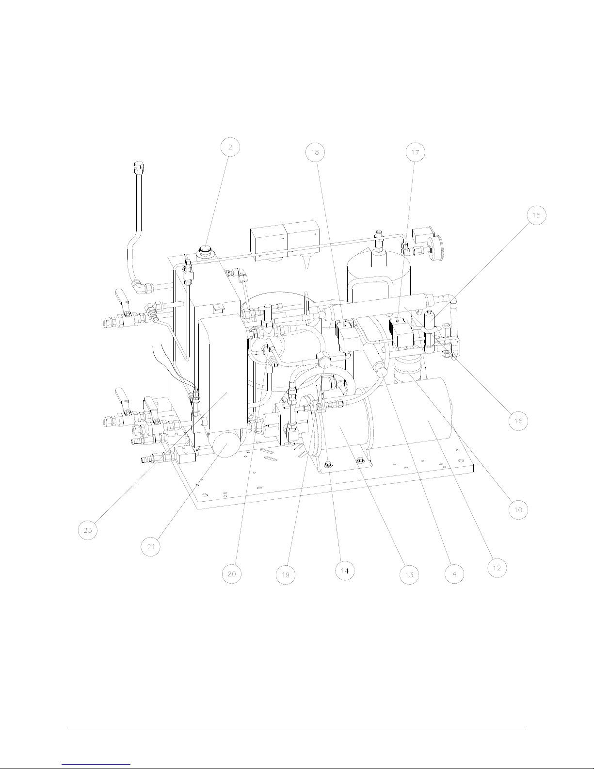
Figure 1, Figure 2, and Table 3 on page 80 describe the refrigeration and coolant components of the TCU
40/80 plus.
(G:\Technical Documents\MANUALS\W95900011- All)
6 TCU 40/80 plus Temperature Control Unit
Figure 1- Refrigeration and Coolant Components

Figure 2 - Refrigeration and Coolant Components
(G:\Technical Documents\MANUALS\W95900011- All)
TCU 40/80 Temperature Control Unit 7

Table 3 - Refrigeration and Coolant Components
Item Component Name Function
1 Reservoir A holding tank for the Fluorinert coolant.
2 Level Switch Monitors the coolant level in the reservoir.
3 Compressor Compresses the refrigerant fluid.
4 Crankcase Regulator Protects the compressor against pressure overload.
5 Suction Service Valve Allows isolation at the compressor.
6 Discharge Service Valve Allows isolation at the compressor.
7 Temperature Switch High limit switch for reservoir heater.
8 Pressure Switch Limits maximum allowable discharge pressure.
9 Condenser Transfers heat from the compressed refrigerant to the facility water.
10 Filter Dryer Removes contaminants and moisture from the refrigerant.
11 Safety Cooling Valve Limits the discharge temperature.
12 Motor Drives the coolant pump.
13 Pump Circulates the Fluorinert coolant.
14 Bypass Valve Regulates coolant flow.
15 Hot Gas Bypass Valve Regulates cooling capacity.
16 Subcooler Further cools the refrigerant that is returning to the compressor.
17 Solenoid Valve SV2 Allows refrigerant to pass through the hot gas bypass valve, then to
the compressor suction line when energized.
18 Solenoid Valve SV1 Allows refrigerant to pass to the TEV when energized.
19 Sight Glass Allows visual inspection of the refrigerant charge and presence of
moisture in the system.
20 TEV
Allows the refrigerant to expand from a liquid to a gas.
(Thermostatic
Expansion Valve)
21 Heater Raises the temperature of the coolant when the process requires
heating.
22 Flow Switch Monitors the flow rate.
23 Heat Exchanger Extracts heat from the coolant and transfers it to the refrigerant.
24 Pressure Relief Valve Discharges refrigerant from the system to the atmosphere in the event
of severe over-pressure condition.
8 TCU 40/80 plus Temperature Control Unit
Fill port
Vent
valve
Coolant
return
Heater
Drain valve
Coolant supply
Pressure
relief
valve
temperature
Bypass valve
Level switch
TS1
Temperature
switch
RTD
probe
Circulation
pump
Plate
heat
exchanger
FS1
TEV
bulb
Thermal
expansion
valve
Flow
switch
Subcooler
Main cooling
solenoid valve
SV1
Crankcase
pressure
regulator
Bypass
valve
Compressor
Service
valve
Hot gas
solenoid valve
SV2
Safety
cooling
TEV
Service
valve
TEV
bulb
Pressure
relief
valve
Filter
dryer
PS1
Pressure
switch
Water out
Condenser
Water in
4.2
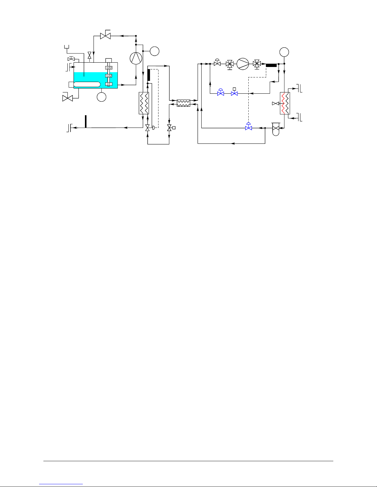
Figure 3 - Refrigeration and Coolant Circuits
(G:\Technical Documents\MANUALS\W95900011- All)
Refrigeration -
(See figure 3 above)
1. Refrigerant gas enters the compressor at low temperature and pressure. It leaves the compressor at high
pressure and temperature.
2. The gas passes into the condenser, where heat is removed by the external water supply, causing the gas
to condense into a liquid.
3. The cool liquid refrigerant exits the condenser and passes through a filter dryer that removes any
residual moisture or contaminants.
4.2.1 If Cooling Is Required:
1. Solenoid valve SV1 opens (coil energized), allowing the refrigerant to flow into the Thermostatic
Expansion Valve (TEV). The pressure drop across the TEV causes the refrigerant to change from
a liquid to a mixture of liquid and gas.
2. The liquid and gas mixture enters the heat exchanger where it becomes entirely a gas. The
process of expansion from a liquid to a gas reduces the temperature by absorbing energy.
3. The refrigerant leaving the heat exchanger returns to the compressor through the sub-cooler and a
crankcase pressure regulator. The sub-cooler further cools the refrigerant entering the TEV.
4.2.2 If Cooling Is Not Required:
1. Solenoid valve SV1 closes (coil de-energized).
2. Hot refrigerant from the compressor is passed through SV2 (coil energized) and a hot gas bypass
valve before returning to the compressor suction line. This bypassing allows the compressor to run
continuously.
3. Cooling, required to prevent the compressor from overheating, is provided by allowing some of
the liquid from the condenser to pass through the safety cooling automatic expansion valve into
the suction line, thus maintaining the discharge gas temperature below 99 °C.
TCU 40/80 Temperature Control Unit 9
4.3 Coolant Circuit
Coolant is pulled from the reservoir by the circulation pump and transferred to the heat exchanger where it
is cooled by the refrigeration system as required. It then flows to the process equipment by means of the
coolant supply hose. The coolant returns to the TCU 40/80 plus reservoir by means of the coolant return
hose. The coolant system requires 8 liters of coolant for the reservoir plus the volume of the circulation
lines and any other spaces filled with coolant that are attached to the TCU 40/80 plus. To increase the
coolant temperature, the reservoir uses an electrical resistance heater that is controlled by the temperature
controller. The heater must be fully submerged at all times, and if the coolant in the reservoir falls below
3.5 liters, a level switch causes the status alarm signal to automatically shut down the TCU 40/80 plus.
A three-float level switch, a thermostat, and a flow sensor provide coolant status signals to the TCU 40/80
plus control system.
4.4 Temperature Monitoring
A Resistance Temperature Device (RTD) monitors the temperature of the coolant leaving the TCU 40/80
plus and transmits this information to the temperature controller. The TCU 40/80 plus compares the output
of the RTD to the selected process temperature (SV1) and determines if the coolant needs to be cooled or
heated. The temperature controller then operates the main cooling solenoid valve or heater. The coolant
temperature at the supply port on the rear panel is measured by a local, internally connected RTD. If
sensing of process equipment temperature is needed, connect an RTD to J72J3 at the rear panel (See Figure
5 on page 13). For remote connection schematic details, see Figure 16 on page 56.
4.5 Front Panel
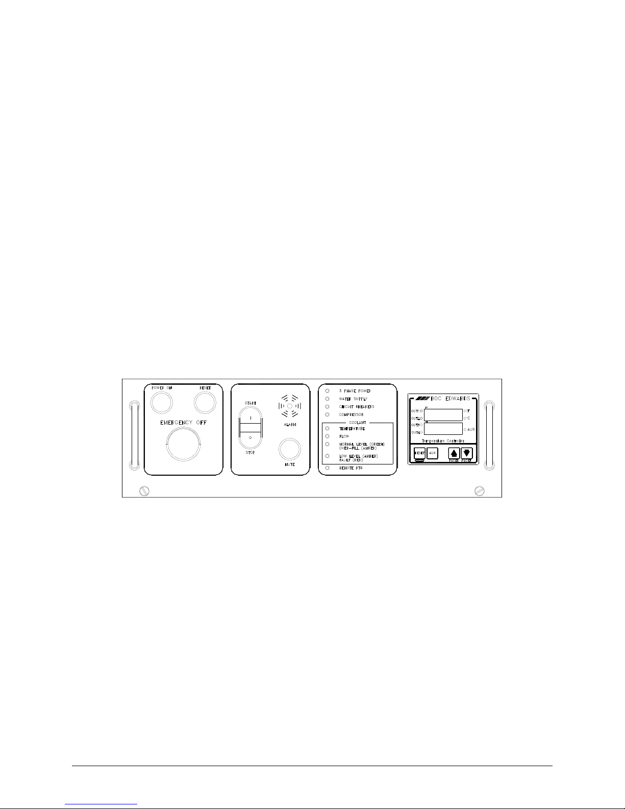
Figure 4 shows the Front Panel. Table 4, Table 5 and Table 6 identify its controls and indicators.
Figure 4 - Front Panel
(G:\Technical Documents\MANUALS\W95900011- All)
10 TCU 40/80 plus Temperature Control Unit

Table 4 - Front Panel Controls
Control Name Description
Power On Lights green when power is being supplied to the TCU 40/80 plus.
Reset Resets alarms and makes the TCU 40/80 plus ready to operate. The white light
indicates that the TCU 40/80 plus is ready to operate.
Emergency Off Removes power from all TCU 40/80 plus circuits except the EMERGENCY
OFF circuit. To shut off power, push EMERGENCY OFF (EMO). To reset,
rotate the EMERGENCY OFF button clockwise as shown on the switch.
Start/Stop Starts and stops the operation of the TCU 40/80 plus.
Alarm Emits a high pitched sound when there is a fault condition which has caused the
TCU 40/80 plus to stop operation.
Mute Silences the audible alarm.
Table 5 - Front Panel LED Indicators
LED Name Condition Description
Facility Power Green
Red
Facility Water
Green
Red
Circuit Breakers
Green
Red
Compressor Green
Red
Coolant Temperature Green
Red
Coolant Flow
Green
Red
Coolant Normal Level Green
Amber
Coolant Low Level Off
Amber
Red
Remote RTD
Off
Green
Power phases are normal.
Power phases are reversed or low line voltage.
Water pressure and flow are normal.
Water pressure or flow are not adequate. (See Specifications
Section 4.7 on page 14.
Rear panel circuit breakers 2, 3, and 4 are on.
One or more of these breakers is tripped or off.
Compressor is operating normally.
Compressor has stopped operating.
Coolant reservoir temperature is normal.
Coolant temperature is above the operating range.
Coolant flow is normal.
Coolant flow is not adequate.
Coolant level is normal .
Coolant level is over filled.
Coolant level is normal
Coolant level is low.
Coolant level is very low.
Remote RTD not connected.
Remote RTD temperature probe is in use.
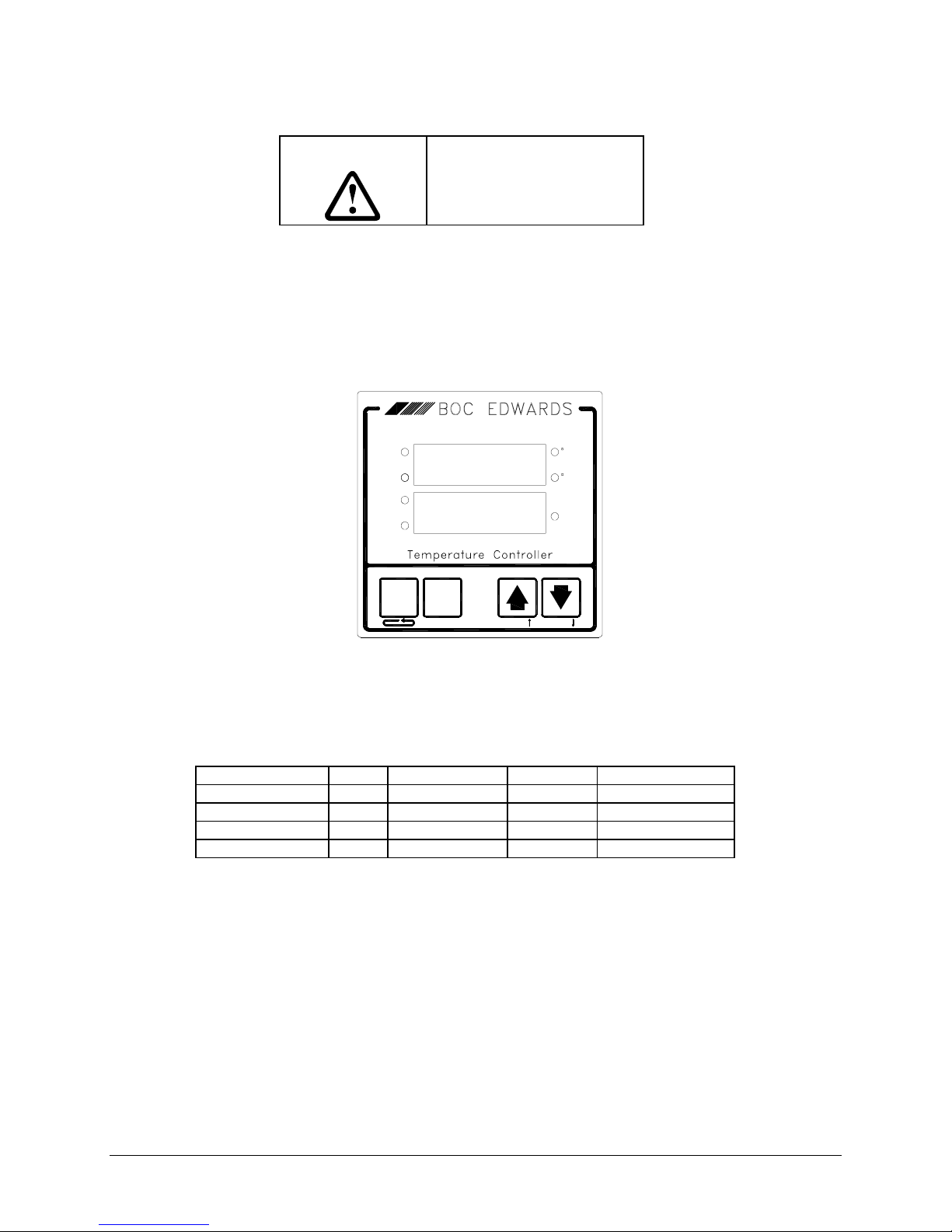
Table 6 - Temperature Controller
Controls and
Description
Indicators
Process Value (PV) The present temperature of the coolant, as indicated by the internal RTD or the
remote RTD.
Setpoint Value (SP) The TCU 40/80 plus regulates to this temperature, as set by the operator.
Pushbuttons Used to program the controller.
Remote Mode Led
(AUX)
Indicates mode of operation:
Off indicates local operation.
On indicates remote operation.
TCU 40/80 Temperature Control Unit 11

4.6 Rear Panel **
Figure 5 shows the rear panel. Table 7 identifies the controls and indicators on the rear panel.
Figure 5 - Electrical Rear Panel
(G:\Technical Documents\MANUALS\W95900011- All)
Table 7 - Description of Rear Panel Components and Indicators
Label Description
J72J3 Five-pin connector for remote RTD interface. See Figure 16 on page 56 for
pinouts.
CB7 24 VAC 1-pole, 2 Amp circuit breaker. Isolates the 24 VAC transformer. Normally on
(in).
CB8 24 VDC 1-pole, 2 Amp circuit breaker. Isolates the 24 VDC power supply output.
Normally on (in).
J72J2 Nine pin connector for remote EMERGENCY OFF, start-stop operation, and
remote setpoint operation enable. See Figure 16 on page 56 for pinouts.
CB4 Reservoir Heater 3-pole, 10 Amp circuit breaker. Normally on (up).
CB3 Circulation Pump 3-pole, 6 Amp circuit breaker. Normally on (up).
CB2 Compressor 3-pole, 16 Amp circuit breaker. Normally on (up).
CB1 Main Power 3-pole, 25 Amp circuit breaker. Normally on (up).
Normal/Overfill Normal, LED Green
Overfilled, LED Amber
Low/Fault Low, LED Amber
Fault, LED Red
200/208 VAC 3 PH
Mains input power connector.
50/60 Hz 30A
CB5-XFMR 2-pole, 0.5 Amp circuit breaker. Isolates the equipment transformer.
CB6-PSU 2-pole, 0.3 Amp circuit breaker. Isolates the power supply.
J72J1 37 pin D-subminiature connector, for setpoint value signal, process value
signal, and remote fail and warning signals.
See Figure 16 on page 56 for pinouts.
** Note: If LONWORKS/RS-485/RS-232 option is chosen, see specific chapter for modified rear panel
details.
12 TCU 40/80 plus Temperature Control Unit

4.7 Specifications
Parameter Conditions Specification
Temperature Ramp Coolant Short Circuit Conditions
Cooling capacity @ process
equipment
150 watt coolant line losses;
coolant water @ 15 °C
Heating Element 2800 Watts
System Flow
Process Temperature Range
Setpoint Resolution
Temperature Regulation
Facility Water Requirements
Process Coolant @ -40 °C
Process Coolant @-20 °C to +80
+25 °C to +80 °C
+25 °C to -30 °C
°C
@20 °C, 60 psig
+10 °C (-0° +2°) to
+26 °C (+0° -2°)
Elapsed Time: <25 Minutes
Elapsed Time: <15 Minutes
750 Watts
2400 Watts
3 gpm (11.36 l pm)
-40 °C to +80 °C
± 0.1 °C
± 1.0 °C Typical
3 to 6 gpm
(11.36 to 22.71 l pm)
Power Requirements
Ambient Operating Temperature
Weight
Dimensions
Altitude
Max. Relative Humidity
Transient Over-Voltage IEC 664, Installation Category II 2.5 kV
Pollution Degree IEC 664
Sound Pressure Level At a distance of 1meter. 65dB(A)
3-Phase Delta (Balanced Load),
4 Wire (3 Phases & Earth Gnd),
200 To 208 VAC, 50/60 Hz
Up to 31 °C
Above 31 °C Derate Linearly to 50% @ 40 °C
30 Amp Outlet
+10 °C to +40 °C
416 lbs. (190kg) Dry Weight
460 lbs. (210 kg) Wet Weight
832 lbs. (308 kg) Dry Weight
Dual Stacked
920 lbs. (420 kg) Wet Weight
Dual Stacked
22" wide x 30" deep x 35" high
(56 cm x 76 cm x 89 cm)
Up to 2000 Meters
(6562 ft.)
80%
2 Π
TCU 40/80 Temperature Control Unit 13

4.8 Dimensions
30.0
[762.0]
22.0
[558.8]
BOC ED WARD S
30.0
[762.0]
35.1
[892.3]
Figure 6 - TCU 40/80 (TCU 40/80
plus
) Dimensions
G:\Technical Documents\MANUALS\W95900011- All)
2
6
5
5
8
.
8
0
2
2
.
0
0
7
0
0
.
0
3
R
0
2
0
O
.
6
0
O
7
3
4
L
0
5
F
.
1
.
1
5
M
9
3
8
O
R
F
CENTER OF GRAVITY
SINGLE
DUAL STACKED
X Y Z
11.10 16.86 17.02
11.10 16.86 33.83
1
2
Z
Y
3
Figure 7 - TCU
40/80 (TCU 40/80
plus
) Dimensions
(G:\Technical Documents\MANUALS\W95900011- All)
14 TCU 40/80 plus Temperature Control Unit

5.4.3 Water
Connections to the water supply and return are made to either ½" brass barb fittings or ½"
compression fittings.
For bare hose connections (½" nominal ID):
1. Slip the hose over the barb fitting and tighten the hose clamp.
2. Turn on the water supply and check for leaks.
For connections using hose with tube adapters or tubing (½" nominal OD):
1. Remove the adapter coupled to the hose barb.
2. Insert the tube adapter or tubing with the appropriate ferrule and compression nut.
3. Tighten the compression nut, turn on the water supply, and check for leaks.
(G:\Technical Documents\MANUALS\W95900011- All)
5.4.4 Coolant
Note: If this TCU 40/80
coolant other than Fluorinert, contact process equipment supplier for retrofit instructions.
Connections to the coolant supply and return are made on the rear panel (See Figure 9 on page
19). The maximum distance between the process equipment and the TCU 40/80 plus is 50 feet
(100 feet total hose length).
1. Attach the hoses to the supply and return compression fittings. Follow the hose manufacturer
recommendations for appropriate adapters.
2. Insulate the hoses with closed cell insulation in order to minimize heat loss.
3. Tape and glue the insulated joints to avoid condensation and icing.
5.4.5 Remote Connections
Wiring details for remote connections are shown in Figure 16 on page 56. Remote connections
should not be run near or parallel to A.C. power lines or in the vicinity of equipment that generates
large electric fields.
Figure 10 - Water Connections
plus
is being installed on process equipment that has been used with a
18 TCU 40/80 plus Temperature Control Unit

5. Installation
5.1 Receiving and Unpacking
Do a complete visual inspection of the TCU 40/80 plus for any damage. Do not use the TCU 40/80 plus
if physical damage is evident. If there is any damage, notify your supplier and the carrier in writing
within three days; state the item number of the TCU 40/80 plus together with your order number and
supplier's invoice number. Retain all packing materials for inspection.
Caution
5.2 Location
Allow a space 46" wide x 54" deep for the TCU 40/80 plus cable and coolant connections. The TCU
40/80 plus should have at least two feet of clearance at the rear and one foot along the sides of the unit.
Be sure that the mounting surface can safely support the weight of the TCU 40/80 plus (460 lbs. evenly
distributed). The center of gravity is approximately the center of the refrigeration compartment.
When using a forklift to move the TCU 40/80 plus, position the forks from the side of the unit.
When using a forklift to move or position the TCU
40/80 plus, do not install the secondary containment
receptacle until the TCU 40/80 plus is in position.
Failure to follow these instructions may lead to
damage of the secondary containment receptacle
caused by the forks of the forklift.
Warning
A 3 ft. (1m) service length of the power cable is required to fully open the electrical drawer. Therefore,
do not install the TCU 40/80 plus further than 7 feet (2.1m) from the power source.
5.2.1 Securing the Unit
The four lockable casters of the TCU 40/80 plus swivel to provide maximum maneuverability.
Make sure that all four casters are turned inward and locked in position once the TCU 40/80 plus
is situated.
5.2.2 Installing the Secondary Containment Receptacle
The secondary containment receptacle slides into the base from the rear of the unit.
5.2.3 Floor Levelers
An optional floor leveler kit is available to compensate for uneven surfaces. See Table 15 on page
57 for ordering information.
The TCU 40/80 plus weighs 460 pounds (210 kg).
Failure to take proper care in moving or lifting these
units can result in serious bodily injury.
TCU 40/80 Temperature Control Unit 15

5.3 Stacking
The TCU 40/80 plus may be stacked two high. Be sure that the mounting surface can safely support the
weight of the two units (920 lbs., 420 kg). Be sure that the casters of the top unit are turned inwards,
but are not locked, until the top unit is fully seated.
5.3.1 Tie-Bolts
An optional tie-bolt kit is available for attaching stacked units. See Table 15 on page57 for
ordering information.
30.0
[762 .0 ]
41.0
[1041.1]
5.4 Facilities
The TCU 40/80 plus requires a water supply flow rate between 3 to 6 gallons per minute at a maximum
pressure of 100 psig, and an inlet temperature range of 10 °C to 26 °C. Power input is by a fused,
suitable isolating electrical outlet, 208 VAC, 50/60 Hz, 30 amp, 3-phase delta (balanced load), 3-wire
and earth. The required receptacle type is Hubbell P/N L21-30R2810-A, or equivalent.
5.4.1 50 Hz Installations
5.4.2 Water and Coolant Connections
Figure 8 - Stacked TCU 40/80 (TCU 40/80 plus) systems
(G:\Technical Documents\MANUALS\W95900011- All)
For 50 Hz installations, adjust the Phase Monitor Relay (PMR1). Open the electrical drawer by
loosening the two screws at the front. Locate PMR1 (reference Figure 13). Remove the
“CAUTION” label, and turn the dial to align with the “50” mark. Replace the “CAUTION” label
and close the drawer.
Figure 9 shows a rear view of the TCU 40/80 plus with its water and coolant connections.
16 TCU 40/80 plus Temperature Control Unit

(G:\Technical Documents\MANUALS\W95900011- All)
TCU 40/80 Temperature Control Unit 17
Figure 9 - System Rear View

5.4.3 Water
Connections to the water supply and return are made to either ½" brass barb fittings or ½"
compression fittings.
For bare hose connections (½" nominal ID):
1. Slip the hose over the barb fitting and tighten the hose clamp.
2. Turn on the water supply and check for leaks.
For connections using hose with tube adapters or tubing (½" nominal OD):
1. Remove the adapter coupled to the hose barb.
2. Insert the tube adapter or tubing with the appropriate ferrule and compression nut.
3. Tighten the compression nut, turn on the water supply, and check for leaks.
(G:\Technical Documents\MANUALS\W95900011- All)
5.4.4 Coolant
Note: If this TCU 40/80
coolant other than Fluorinert, contact process equipment supplier for retrofit instructions.
Connections to the coolant supply and return are made on the rear panel (See Figure 9 on page
19). The maximum distance between the process equipment and the TCU 40/80 plus is 50 feet
(100 feet total hose length).
1. Attach the hoses to the supply and return compression fittings. Follow the hose manufacturer
recommendations for appropriate adapters.
2. Insulate the hoses with closed cell insulation in order to minimize heat loss.
3. Tape and glue the insulated joints to avoid condensation and icing.
5.4.5 Remote Connections
Wiring details for remote connections are shown in Figure 16 on page 56. Remote connections
should not be run near or parallel to A.C. power lines or in the vicinity of equipment that generates
large electric fields.
Figure 10 - Water Connections
plus
is being installed on process equipment that has been used with a
18 TCU 40/80 plus Temperature Control Unit

6. Operation
6.1 Preparation
Verify that water and coolant connections are made at both ends that the drain valve is closed and the
coolant supply and return valves are open. Connect the remote interfaces if required.
1. To use an external RTD probe, attach it to connector J72J3. Refer to Figure 16 on page 60. Verify
that the plug J72J2 is installed.
2. Press the EMERGENCY OFF button on the front panel.
3. Plug the TCU 40/80 plus power cord into a fused, switchable, 30 amp, 3-phase, 208 VAC outlet.
4. Ensure that all circuit breakers on the rear panel are in the ON position. CB7 and CB8 are non switchable circuit breakers and will trip when there is a problem. They cannot be turned on or off,
but they are re-settable.
6.2 Powering up the TCU 40/80 plus
1. Verify that the POWER ON lamp on the front panel is illuminated.
2. Release the EMERGENCY OFF button.
Caution
3. Press the RESET button and verify the front panel indicators are as in the Reset Condition
column of Table .
Remote RTD (If Used) Green Green
4. Press MUTE to silence the alarm.
The TCU 40/80 plus is shipped without coolant. The coolant level alarm will sound and the front
panel Reservoir Coolant Low Level LED will be red indicating that the reservoir must be filled.
5. Fill the coolant reservoir using the procedure Filling the Reservoir on page 31.
6. Press the START button and verify the front panel indicators are as in the Start Condition column
of Table 8.
7. Use a halogen leak detector to check all supply and return line connections at both the TCU and
process equipment, around the pump head assembly, drain valve, heater, flow switch, vent line,
fill line, and reservoir pressure relief valve.
If the Facility Power LED
illuminates, the line voltage is low, or
the phase of the main power supply
is reversed.
Table 8 - Front Panel Power Up Indicator Conditions
Indicator Reset Condition Start Condition
Power On Green Green
Reset Off White
Facility Power Off Green
Facility Water Green Green
Circuit Breakers Green Green
Compressor Off Green
Temperature Green Green
Flow Off Green
Normal Level Off Green
Low Level Red Off
Adjust the line voltage, if it is low.
Correct the phases by swapping two
phases in the electrical outlet.
TCU 40/80 Temperature Control Unit 19
6.3 Changing the Setpoint Value (SV1)
The following instructions are for local temperature control only.
Caution
To change the temperature settings press page up or page down to either increase or decrease the
temperature. The red display “PV” indicates the process value. The green display “SP” indicates the current
setpoint.
Note: The temperature controller has been programmed to prevent the setpoint from exceeding the normal
operating range of the TCU 40/80
PID and other settings. Contact the process equipment supplier for access to these settings and other
information.
plus
Do not exceed the temperature
range of -40 °C to +80 °C.
This is the normal operating
range of the TCU 40/80 plus.
. The controller is also protected from unauthorized changes to the
PV
OUT 1
OUT 2
SP
OUT 3
OUT 4
AUXRESET
Figure 11 - Temperature Controller
(G:\Technical Documents\MANUALS\W95900011- All)
6.4 Temperature Controller PID Settings
BOC Edwards default settings are:
PID1 - Heating Value PID2 - Cooling Value Parameter
Pb1 14.0 Pb2 18.0 Proportional Band
Ar1 1.0 Ar2 4.5 Automatic Reset
rAt1 3.0 rAt2 4.0 Rate
db1 1.0 db2 1.0 Deadband
6.5 Remote Set-Point
To use the remote set point, wire the J72J2 mating connector as illustrated on page 56.
24vac must be applied to pins 3 and 4.
The AUX LED on the temperature controller will illuminate indicating remote setpoint enable mode as
soon as the mating connector is installed.
F
C
AUX
PAGE PAGE
20 TCU 40/80 plus Temperature Control Unit

6.6 Flow Rate Adjustment
Caution
The Fluorinert flow rate of the TCU 40/80 plus is factory set to provide approximately 3 gpm at
60 psig/20°C for a unit operating at 208vac/3-ph/60Hz. If the flow rate requires adjustment to
accommodate the process equipment suppliers’ recommendations, follow the steps below. The flow rate
may be measured using a flow meter external to the TCU 40/80 plus.
1. Open the left side access door.
2. Peel back the insulation covering the by-pass valve. Refer to Figure 1 on page 7.
3. The valve handle can be found in the plastic bag secured to the pump. Reduce the flow by turning the
valve stem clockwise. To increase the flow, turn the stem counter clockwise. The valve is a 1/4 turn
valve.
4. Once the required flow rate has been achieved, return the valve handle to the bag for future use, glue
the insulation back in place, and secure the access door.
Do not exceed coolant pressure of
100 psi.
Exceeding the coolant pressure
may result in damage to the
pump.
TCU 40/80 Temperature Control Unit 21

22 TCU 40/80 plus Temperature Control Unit

7. Maintenance
This section contains information that will allow you to safely keep your TCU 40/80 plus in working order.
It contains important Hazard Warnings, and a Preventive Maintenance Schedule on page 28.
7.1 Hazard Warnings
Warning
Warning
High Pressure
Maintenance to the electrical
system of the TCU40/80 should
be performed by qualified
personnel only.
The refrigeration units are sealed
and are not user serviceable.
Only trained and licensed
refrigeration personnel should
perform repairs on this
equipment.
All applicable EPA regulations
apply.
Water and the coolant are
pressurized within this equipment.
Water pressure will depend upon
utility supply, but usually is up to
60 psig. The coolant can be at
pressures up to 100 psig.
Refrigerant pressures can be up to
300 psig.
Do not open lines with pressure
present.
Toxic Gases
High Pressure
The coolant breaks down above
215 °C. If the coolant is allowed
to reach these temperatures; toxic
gasses may be discharged from
the unit.
Refer to the Appendix for
Material Safety Data Sheets for
the coolant and refrigerant used in
this system.
The reservoir may become
pressurized due to changes in
temperature.
Under no circumstances should
the reservoir pressure relief valve
be removed or capped off.
22 TCU 40/80 plus Temperature Control Unit
High
The refrigerant lines are at high
pressure.
Pressure
Under no circumstances should
Eye
Protection
Hand
Protection
the refrigerant pressure relief
valve be removed or capped off.
Leakage or failure of highpressure circuits may cause injury
or irritation of the eyes.
Eye protection should be worn
when working with fluid systems.
Hot or cold fluids and surfaces
can cause injury or irritation of
the hands.
Hand protection should be worn
when working with these fluid
systems.
Electric
Shock
Hot Surface
Ensure that all electrical power
has been removed and the main
circuit breaker has been turned off
prior to opening the electrical
drawer. The EMERGENCY OFF
circuit (EMO) does not
disconnect all power from the
electrical drawer.
Extreme caution must be
observed if performing
maintenance operations with the
drawer open.
Refrigeration and circulating fluid
lines can attain temperatures as
high as 110 °C.
Caution must be observed.
TCU 40/80 Temperature Control Unit 23

7.2 Hazards
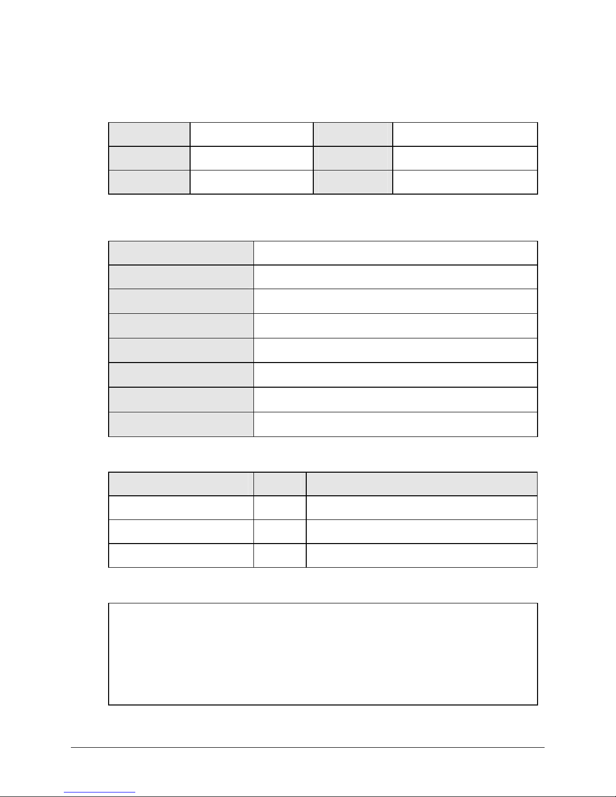
Table 9 gives the classifications of electrical hazards. This number indicates the severity of the
hazard as defined by SEMI S2-93.
Table 9 - Electrical Hazards Classifications
Classification Description Comment
Type 1 Equipment is fully de-energized. None called out.
Type 2 Equipment is energized. Live circuits are covered or
insulated. Work is performed at a remote location to preclude
accidental shock.
Type 3 Equipment is energized. Live circuits are exposed and
accidental contact is possible. Potential exposures are less
than 30 volts RMS, 42.2 volts peak, 240 volt-amps, 20
Joules.
(See NFPA 79-14.3, IEC 204, UL 1950 & 1262, IEC 950.)
Type 4 Equipment is energized. Live circuits are exposed and
accidental contact is possible. Potential exposures are greater
than 30 volts RMS; 42.2 volts peak, 240 volt-amps, 20 Joules
or radio frequency (RF) is present.
Type 5 Equipment is energized and measurements and adjustments
require physical entry into the equipment, or equipment
configuration will not allow the use of clamp-on probes.
Called out as Type 2.
Called out as Type 3.
Called out as Type 4.
None called out.
7.3 Filling the Reservoir
Warning
When retrofitting a TCU 40/80
plus in place of a water/glycol
unit, the coolant lines must be
1. Open the vent port valve (See Figure 9 on page 19) to avoid air locks that may slow filling.
2. Remove the plug and fasten the funnel accessory to the ½" fill port located at the rear of the unit (See
Figure 9 on page 19).
3. Fill the reservoir with Fluorinert heat transfer fluid. The amount needed for a new installation is
approximately 44 pounds for the TCU and an additional amount for process lines (approximately 0.15
pounds/ft of 1/2” tube) and other external volumes.
4. Begin filling the reservoir until the Coolant Normal Level LED on the rear electrical panel turns green.
When the LED turns green, add approximately 4 liters more of fluid (approximately 17 pounds).
5. If this is a new installation, the lines to the tool are empty. If possible, start the TCU. The coolant will
leave the TCU to fill the lines and the level in the TCU reservoir will decrease. Observe the TCU to
determine if the Coolant Low Level LED on the rear panel turns amber. If so, add approximately 4
liters more fluid (approximately 17 pounds).
6. In the event of over-filling, the Coolant Normal LED will change from green to amber. Drain excess
fluid until the Coolant Normal Level LED turns green. Refer to Draining/Bleeding the Coolant
Reservoir, below.
flushed with nitrogen to remove
moisture prior to installation.
24 TCU 40/80 plus Temperature Control Unit
7.4 Draining/Bleeding the Coolant Reservoir
It may be necessary to drain the coolant reservoir for storage of the TCU 40/80 plus or due to
moisture contamination of the coolant.
It may be necessary to bleed the coolant reservoir to correct an overfill condition.
Note: The unit may continue running during this procedure.
Follow the procedure below whenever it becomes necessary to drain or bleed the system.
Extreme
Temperature
Hot or cold coolant may reach 40°C to +80°C during operation.
Hot or cold fluid can cause
burns.
1. Open the vent valve located at the top of the unit.
2. Place an appropriate container beneath the drain valve. The capacity of the container used
needs to be 10 liters plus the volume of the hoses and the volume of the process equipment.
3. Remove the cap fitting from the end of the drain valve.
4. Open the reservoir drain valve.
5. To correct an overfill condition,
a. Drain the reservoir until the Coolant Level Normal LED on the rear electrical panel turns
green. Close the reservoir drain and vent valves when the LED turns green.
b. To empty the reservoir, remove power to the TCU and allow the unit to drain until all
coolant has been removed.
6. Close the reservoir drain and vent valves.
7. For proper disposal of the coolant, follow the manufacturer recommendations.
Note: Uncontaminated Fluorinert may be reused. The Fluorinert should be stored in a compatible
and sealed container.
Coolant should be at ambient
temperature before handling.
7.5 Temperature Probe Calibration
The BOC Edwards Temperature Controller comes equipped with a factory calibrated internal ±10V
remote input/output option making calibration unnecessary.
7.6 Preventive Maintenance Schedule
Table 10 shows the maintenance required to keep the TCU 40/80 plus in good working order.
Failure to follow this schedule may result in degradation of system performance.
Table 10 - Preventive Maintenance Schedule
Frequency Operation Hazard
Verify system status
Check coolant level
Check lamps (Type 3)
Semi-annually Coolant leak check (Type 3)
Refrigeration leak check (Type 3)
Insulation repair (Type 3)
Water leak check (Type 3)
Replace solenoid coils SV1 and SV2 (Type 3)
Annually System check (Type 3)
Lamp replacement (Type 3)
Note: All maintenance should be recorded on the Preventative Maintenance Record label located
on the inside of the left-hand side access panel.
TCU 40/80 Temperature Control Unit 25

7.7 Semi-Annual Preventative Maintenance
Refer to the Troubleshooting section 8 on page43 when results for any of the following
checkpoints are not as expected.
7.7.1 Required Equipment
· 12” slotted screwdriver · Spare lamps (24 vac / 60 mA)
· 4” slotted screwdriver · Fluorinert
· Two 10” adjustable wrenches · Insulation Tape
· Halogen leak detector
7.7.2 Preparation
· Locate the two screws securing each of the side access panels and loosen to open doors.
· Listen for excessive or questionable noise or sounds coming from the pump assembly,
motor, compressor, or solenoid valves (SV1 and SV2).
7.7.3 Verify System Status
· Verify system status led indicators on the front electrical panel.
(See Table 8 on page 21.)
7.7.4 Refrigeration Leak Check
· Visually check for signs of compressor oil on the base, insulation, and on all refrigeration
Tube assembly.
· Using a halogen leak detector check around the discharge and suction service valves of
the compressor, and all accessible refrigeration tube assembly.
7.7.5 Fluorinert Leak Check
· Use a halogen leak detector to check all supply and return line connections at both the
TCU and process equipment, around the pump head assembly, drain valve, heater, flow
switch, vent line, fill line, and reservoir pressure relief valve.
7.7.6 Water Leak Check
· Visually check for signs of water leaks at all water line connections external to the TCU
and at the condenser connections inside the unit.
7.7.7 Insulation Repair
Note: If ice formation is excessive, it may be necessary to correct this condition before
insulation can be repaired.
· Visually inspect refrigeration and process fluid lines both inside the TCU cabinet and at
the supply and return line connections for signs of ice formation. Correct insulation as
necessary.
26 TCU 40/80 plus Temperature Control Unit

7.7.8 Lamp Check/Replacement
Electric
Shock
Caution
Visually verify that the POWER ON and RESET lamps are working. If either lamp needs
replacement and the proper authorization has been obtained:
1. Press STOP.
2. Turn off the main circuit breaker (CB1).
3. Disconnect power cord from mains power supply.
4. Locate the two securing screws on the front electrical panel and loosen. Open the electrical
drawer.
5. If replacing the POWER ON lamp, locate contactor block (LP1) on the backside of the front
electrical panel. If replacing the RESET lamp, locate contactor block (PB1) on the backside of
the front electrical panel.
6. Pry up the metal retaining ring attached to the coupling plate. Remove the contact block
assembly.
7. Replace the defective lamp.
8. Reinstall the contact block assembly by snapping it back onto the front element.
9. Close the electrical drawer and tighten securing screws.
10. Reconnect main power and turn on the main circuit breaker (CB1). The POWER ON lamp
should be illuminated.
11. Press RESET. The lamp should illuminate. Press START to reactivate the TCU.
Ensure all electrical power has
been removed and the main
circuit breaker has been turned
off due to the presence of high
voltage or current.
Should a lamp require
replacement, notify the
appropriate personnel that an
EMO condition will occur.
Failure to follow these
instructions may result in the
shutdown of the process tool
and associated equipment.
(G:\Technical Documents\MANUALS\W95900011- All)
TCU 40/80 Temperature Control Unit 27
Figure 12 - Lamp Replacement

7.8 Annual Preventative Maintenance
Refer to the Troubleshooting section 8 on page47 when results for any of the following checkpoints are not
as expected.
7.8.1 Required Equipment
· 12” slotted screwdriver · Miniature diagonal cutters
· 4” slotted screwdriver · Halogen leak detector
· 7” slotted screwdriver · 3\8” open-ended wrench
· 8” Phillips screwdriver · 1\4” open-ended wrench
· Two 10” adjustable wrenches · Wire crimpers - Insulated terminal
· Wire strippers (14 AWG) · Digital multimeter (DMM)
· Two test clips w/12” leads · Remote RTD connector plug (J72J3)
7.8.2 Required Supplies
· Preventative Maintenance Kit (P60153005)
· Fluorinert
· Insulation Tape
7.8.3 Solenoid Valve Coil Replacement
Electric
Shock
Caution
1. Press STOP. Turn off the main circuit breaker (CB1).
2. Disconnect the power cord from the mains power supply.
3. Locate the main cooling solenoid valve (SV1) from the left side access door.
4. Remove the junction box attachment screw. Slide off the junction box cover.
5. Back off the strain relief-retaining nut.
6. Unfasten the ground screw. Cut off the wire butt splices (ensuring that the wire labels remain
attached to the base assembly) and pull the wires through the junction box.
7. Remove the solenoid valve coil lock nut. Lift off the spacer cup. Separate the coil from the
solenoid valve body by gently pulling up on the coil.
8. Remove replacement solenoid valve coil from packaging.
9. Remove the junction box.
10. Note the location of the conduit hole on the coil removed and remove the appropriate “knock-
out” on the replacement coil.
11. Gently slip the replacement coil onto enclosing tube of solenoid valve body.
12. Pull the base assembly wiring through conduit hole and slip on the strain relief-retaining nut.
13. Attach the ground wire to coil.
Ensure all electrical power has
been removed and the main
circuit breaker has been turned
off due to the presence of high
voltage or current.
Should a solenoid valve coil
require replacement, notify the
appropriate personnel that an
EMO condition will occur.
Failure to follow these
instructions may result in the
shutdown of the process tool and
associated equipment.
28 TCU 40/80 plus Temperature Control Unit

14. Strip the ends of all wires on base assembly and solenoid valve coils.
15. Attach wires and secure mating connections per figure 13 below.
16. Tighten the strain relief-retaining nut.
17. Install the original junction box cover and fasten attachment screw.
18. Install the spacer cup.
19. Install and tighten the lock nut.
20. Verify the coil junction box is labeled SV1.
21. Repeat the procedure for Hot Gas Bypass solenoid valve coil (SV2).
22. Discard the old solenoid coils.
23. Perform the System Check procedure.
RED WIRE
WHITE WIRE
Junction Box Cover
P43018200
P43018300
Ground Screw
Retaining Nut
Lock Nut
Spacer Cup
(G:\Technical Documents\MANUALS\W95900011- All)
TCU 40/80 Temperature Control Unit 29
Figure 13 - Solenoid Coil Replacement
7.8.4 System Check
Component Settings
Motor Overload Setting (K3) 3.5 amps
Current Sensing Relay Setting (CSR) 25 amps
Thermostat Setting (TS1) 210°F (Differential set at 10°F)
High Pressure Switch Setting (PS1) 300 psig. (Differential set at 40 psig)
Power-Up Conditions
· Power cord connected to mains power supply.
· All circuit breakers on.
· EMO released.
· Drawer interlock switch in maintenance position.
· Host connector J72J2 installed (Pins 5 & 6 shorted).
Indicator Condition
Relays All off
LED All off
Power On
Reset Off
PMR Green
Current Sensing Relay Off
Note: REMOTE RTD is optional. LED will be green if used.
Reset Button
1. Press RESET.
2. Verify contactor K1 engages.
3. Verify LED indicator on PMR is green.
Indicator Condition
Relays CR1, CR4, & CR12 on all others off
LED Facility Water, Circuit Breakers, Coolant
Temperature, Coolant Normal Level, Green
Facility Power, Compressor, Coolant Flow, Coolant
Low Level, Remote RTD, Off
Power On
Reset On
PMR Green
Current Sensing Relay Off
Note: REMOTE RTD is optional. LED will be green if used.
30 TCU 40/80 plus Temperature Control Unit

Temperature Controller
1. All control parameters and selections procedures for the temperature controller are
accomplished through simple MENU selections. These MENU selections are organized
into PAGES. On each page you will find a specific set of related functions. The PAGES
setup structure is as follows: diSP PAGE, Ctrl PAGE, inPt PAGE, ScAL PAGE, Out1
PAGE and Out2 PAGE.
To select a PAGE:
Press and hold the RESET key, while pressing the or keys. The upper display of
the temperature controller will increment or decrement through the PAGEs, and PAGE
will be displayed in the lower display.
To select a MENU:
After reaching the correct page, press reset to move through MENUs. The alpha cue for
the MENU will appear on the upper display and the current value will appear in the lower
display.
To change a MENU value:
After the MENU is selected and displayed, use the and keys to change the value.
2. To enter the SetUp Mode, press the controller RESET key and hold it for about 3
seconds. The controller will display LocH XXX where XXX is the security code. The
security code number should be 458. If not, press either the or keys until the
display reads 458. This is the first menu in the Ctrl PAGE.
3. Verify that the menu settings for the Ctrl PAGE are as follows:
PID1 - Heating Value PID2 - Cooling Value Parameter
Pb1 14.0 Pb2 18.0 Proportional Band
Ar1 1.0 Ar2 4.5 Automatic Reset
rAt1 3.0 rAt2 4.0 Rate
db1 1.0 db2 1.0 Deadband
OFst = 0.0 FL = On Orng = 0.0 LooP = OFF Auto = 4 rrAt = OFF Cont = HtCl
CooL = PID2 rSP = On Enti = rSP Au = none Aout = Proc rSEn = OFF
4. Select the next page, which is the InPT PAGE. Verify that the menu settings for the InPt
PAGE are as follows:
SEnS = rtdt unit = °C CoFF = .0 SPLL = -40.0 SPUL = 80.0
5. Select the next page, which is the ScAL PAGE. Verify that the menu settings for the
ScAL PAGE are as follows:
DP = 1 AinL = -50.0 AinH = 100.0 AotL = -100.0 AotH = 100.0 rSPL = -100.0
rSPH = 100.0
6. Select the next page, which is the Out1 PAGE. Verify that the menu settings for the
Out1 PAGE are as follows:
Cyc1 = 16 OL1 = 100.0 HoFF = .0
7. Select the next page, which is the Out2 PAGE. Verify that the menu settings for the
Out2 PAGE are as follows:
Cyc2 = 16 OL2 = 100.0 CoFF = .0
8. Press START.
To return to Operating Mode, press and hold the RESET key for more than 3 seconds.
The controller will automatically return to operating mode after 10 minutes of no pushbutton activity.
9. Press START.
TCU 40/80 Temperature Control Unit 31
EMO Circuit
Do not perform the EMO
Warning
circuit check while the TCU is
on-line with the process tool.
Failure to follow these
instructions will lead to the
shutdown of the process tool
and other associated equipment.
1. Press the EMO button and check that the following occur.
· READY lamp goes out.
· All front panel LED indicators go out.
· Temperature controller shuts off.
· K1 contactor opens.
2. Release the EMO button and press RESET. Perform the following:
· Remove rear panel connector J72J2. The READY lamp should go out. Contactor K1
should open, the temperature controller and the front panel LED indicators should go
out. Replace J72J2 connector and press RESET.
3. Press in the interlock switch then release it. The READY lamp should go out. Contactor
K1 should open, the temperature controller and the front panel LED indicators should go
out. Place the drawer interlock switch in the maintenance position.
· Press RESET
· Press START
PMR
1. On the PMR rotate the adjustment knob completely clockwise.
2. Verify the unit shuts down, LED 1 (Facility Power) illuminates red, and that the alarm
sounds.
3. Press MUTE.
Indicator Condition
Relays CR1, CR4, CR11, CR12, CR13
On all others, Off
LED Facility Water, Circuit Breakers, Coolant
Temperature, Coolant Normal Level, Green
Compressor, Coolant Flow, Coolant Low Level,
Remote RTD, Off
Facility Power, Red
Power On
Reset Off
PMR Red
Current Sensing Relay Off
Note: REMOTE RTD is optional. LED will be green if used.
4. Return the PMR adjustment control to the original position.
5. Press RESET then START
32 TCU 40/80 plus Temperature Control Unit

Current Sensing Relay
1. Set CSR1 to 50 amps. The indicator LED on CSR1 should go from green to red.
2. After a 5 second time delay, verify that the unit shuts down, COMPRESSOR illuminates
red and the alarm sounds.
3. Press MUTE.
Indicator Condition
Relays CR1, CR4, CR8, CR11, CR12, CR13
On all others, Off
LED Facility Water, Circuit Breakers, Coolant
Temperature, Coolant Normal Level, Green
Facility Power, Coolant Flow, Coolant Low Level,
Remote RTD, Off
Compressor, Red
Power On
Reset Off
PMR Green
Current Sensing Relay Off
Note: REMOTE RTD is optional. LED will be green if used.
4. Reset CSR1 to 25 amps.
5. Press RESET.
6. Press START.
Circuit Breaker
1. Power off CB4. The TCU will shut down, alarm will sound and CIRCUIT BREAKER LED
should be red.
2. Press MUTE.
3. Power on CB4, press START.
4. Repeat steps 1 through 3 for CB3 and CB2.
Indicator Condition
Relays CR4, CR11, CR12, CR13
On all others, Off
LED Facility Water, Coolant Temperature, Coolant
Normal Level, Green
Facility Power, Compressor, Coolant Flow,
Coolant Low Level, Remote RTD, Off
Circuit Breakers, Red
Power On
Reset Off
PMR Green
Current Sensing Relay Off
Note: REMOTE RTD is optional. LED will be green if used.
TCU 40/80 Temperature Control Unit 33

Water Supply
1. Open TCU right side panel and remove PS1 cover. Using a flat head screwdriver, lift up PS1
tab. The TCU will shut down, alarm will sound, and FACILITY WATER LED should
illuminate red.
2. Press MUTE.
Indicator Condition
Relays CR1, CR2, CR4, CR11, CR12, CR13
On all others, Off
LED Circuit Breakers, Coolant Temperature, Coolant
Normal Level, Green
Facility Power, Compressor, Coolant Flow,
Coolant Low Level, Remote RTD, Off
Facility Water, Red
Power On
Reset Off
PMR Green
Current Sensing Relay Off
Note: REMOTE RTD is optional. LED will be green if used.
3. Reinstall PS1 cover.
4. Press RESET.
5. Press START.
Reservoir Over-Temperature
1. Open TCU right side panel and remove TS1 cover. Using a flat head screwdriver, lift up TS1
tab. The TCU will shut down, alarm will sound and COOLANT TEMPERATURE LED
should be red.
2. Press MUTE.
Indicator Condition
Relays CR1, CR4, CR6, CR11, CR12, CR13
On all others, Off
LED Facility Water, Circuit Breakers, Coolant
Normal Level, Green
Facility Power, Compressor, Coolant Flow,
Coolant Low Level, Remote RTD, Off
Coolant Temperature, Red
Power On
Reset Off
PMR Green
Current Sensing Relay Off
Note: REMOTE RTD is optional. LED will be green if used.
3. Reinstall TS1 cover.
4. Press RESET.
5. Press START.
34 TCU 40/80 plus Temperature Control Unit
Coolant Flow
1. Shut off coolant supply valve. After 5 second delay, the TCU will shut down, alarm will
sound and COOLANT FLOW LED should be red.
2. Press MUTE.
Indicator Condition
Relays CR1, CR4, CR7, CR11, CR12, CR13
On all others, Off
LED Facility Water, Circuit Breakers, Coolant
Temperature, Coolant Normal Level, Green
Facility Power, Compressor, Coolant Low
Level, Remote RTD, Off
Coolant Flow, Red
Power On
Reset Off
PMR Green
Current Sensing Relay Off
Note: REMOTE RTD is optional. LED will be green if used.
3. Open coolant supply valve.
4. Press RESET
5. Press START
Compressor
1. Remove wire #60 from CSR1. After 5 second delay, the TCU will shut down, alarm will
sound and COMPRESSOR LED will be red.
2. Press MUTE.
Indicator Condition
Relays CR1, CR4, CR8, CR11, CR12, CR13
On all others, Off
LED Facility Water, Circuit Breakers, Coolant
Temperature, Coolant Normal Level, Green
Facility Power, Coolant Flow, Coolant Low
Level, Remote RTD, Off
Compressor, Red
Power On
Reset Off
PMR Green
Current Sensing Relay Off
Note: REMOTE RTD is optional. LED will be green if used.
3. Reinstall wire #60 to N.O. contact of CSR1.
4. Press RESET.
5. Press START.
TCU 40/80 Temperature Control Unit 35

Circulation Pump
1. Adjust overload trip on K3 to the minimum setting. Within three minutes the overload will
trip. After a five second time delay, the TCU will shut down, the alarm will sound and the
COOLANT FLOW LED should illuminate red.
2. Press MUTE.
Indicator Condition
Relays CR1, CR4, CR7, CR11, CR12, CR13
On all others off
LED Facility Water, Circuit Breakers, Coolant
Temperature, Coolant Normal Level, Green
Facility Power, Compressor, Coolant Low
Level, Remote RTD, Off
Coolant Flow, Red
Power On
Reset Off
PMR Green
Current Sensing Relay Off
Note: REMOTE RTD is optional. LED will be green if used.
3. Reset overload trip to 3.5 amps.
4. Press RESET
5. Press START
Reservoir Overfill
1. Short wire #23 (TB1) to wire #63 (Relay board J3-4). COOLANT NORMAL LEVEL LED
will go from green to amber.
Indicator Condition
Relays CR1, CR4, CR5, CR10
On CR12, Off
LED Facility Power, Facility Water, Circuit
Breakers, Compressor, Coolant Temperature,
Coolant Flow, Coolant Normal Level, Green
Coolant Low Level, Remote RTD, Off
Coolant Normal Level, Amber
Power On
Reset On
PMR Green
Current Sensing Relay Green
Note: REMOTE RTD is optional. LED will be green if used.
36 TCU 40/80 plus Temperature Control Unit
Remote Start/Stop
1. Remove jumper from terminal strip (TB1). The TCU will shut down.
2. Press RESET.
3. Press START.
Remote Temperature Probe
1. Install connector J72J3 and verify REMOTE RTD illuminates green.
Indicator Condition
Relays CR1, CR4, CR9, CR10, CR12
On all others, Off
LED Facility Power, Facility Water, Circuit
Breakers, Compressor, Coolant Temperature,
Coolant Flow, Coolant Normal Level,
Remote RTD, Green
Coolant Low Level, Off
Power On
Reset On
PMR Green
Current Sensing Relay Green
2. Remove connector J72J3.
Cooling
1. Change the temperature controller set point to -40°C.
2. Verify CR15 on the relay board illuminates.
3. Verify main solenoid valve (SV1) has opened by confirming that the sight glass has filled
with refrigerant.
4. Verify OUT 2 LED on the temperature controller is on.
Indicator Condition
Relays CR1, CR4, CR10, CR12, CR15
On all others, Off
LED Facility Power, Facility Water, Circuit
Breakers, Compressor, Coolant Temperature,
Coolant Flow, Coolant Normal Level,
Remote RTD, Green
Coolant Low Level, Remote RTD, Off
Power On
Reset On
PMR Green
Current Sensing Relay Green
Note: REMOTE RTD is optional. LED will be green if used.
TCU 40/80 Temperature Control Unit 37
Heating
1. Change the temperature controller set point to 80°C.
2. Verify contactor K4 pulls in.
3. Verify CR15 goes out. Verify OUT 1 on the temperature controller is on and OUT 2 is off.
4. Verify hot gas bypass solenoid (SV2) is energized.
Indicator Condition
Relays CR1, CR4, CR10, CR12
On all others, Off
LED Facility Power, Facility Water, Circuit
Breakers, Compressor, Coolant Temperature,
Coolant Flow, Coolant Normal Level,
Remote RTD, Green
Coolant Low Level, Remote RTD, Off
Power On
Reset On
PMR Green
Current sensing relay Green
Note: REMOTE RTD is optional. LED will be green if used.
Process Value Setting
1. Set the temperature controller to the proper process set value.
2. Verify all the host interface connections are mated properly.
38 TCU 40/80 plus Temperature Control Unit
7.9 Preventive Maintenance Checklist
Record Date:
Customer Name:
Checked By:
System Status
Timer Hours:
Coolant Pressure:
Process Temperature:
Fluorinert Type:
Quantity Of Fluorinert Added:
Operation Mode:
Utilities Water Temperature:
Leak Check Results:
Parts Replaced
Actions / Concerns
FC8270 FC77
Remote Local
Pass
Quantity Cause / Reason
Serial No:
Line / Area:
Tool Name:
Hours
psig
°C
lbs.
°C
Fail
Other:
Liters
Remarks:
TCU 40/80 Temperature Control Unit 39

8. Troubleshooting
Table 11, Table 12, Table 13 and Table 14 identify fault conditions that may encounter with the TCU 40/80
plus. For additional assistance contact the BOC Edwards Service Department.
Table 11 - Faults Identified By Front Panel Lamps
Indicator Possible Causes Action Hazard
POWER ON lamp
is not
illuminated.
The main power circuit
POWER ON lamp
The transformer isolating
The transformer isolating
One of the following
No power to the TCU
40/80 plus.
breaker (CB1) is off.
requires replacement.
circuit breaker CB5 may
be off.
circuit breaker CB7 may
be tripped.
circuit breakers may not
be functional:
· main power circuit
breaker (CB1)
· transformer isolating
circuit breaker CB5
· transformer isolating
circuit breaker CB7
Verify that the power cord is plugged in.
Verify that outlet's circuit breaker is on.
Verify that the outlet’s EMO is not activated.
Verify that the main power circuit breaker
(CB1) is on.
Verify that the POWER ON lamp assembly
is receiving 24 VAC. To do this, opening of
the electrical drawer is necessary. This will
activate the drawer interlock switch and shut
the TCU 40/80 plus down.
Notify the tool operator prior to opening the
electrical drawer.
Check to see that 24 VAC is present across
the lamp assembly terminal block (LP1),
terminals X1 and X2. If 24 VAC is present,
then replace the POWER ON lamp. (EHVI
part no. P23247900).
Refer to the “Lamp Check/Replacement”
Section 7.7.8 page 30.
Verify that the transformer isolating circuit
breaker CB5 is on.
Verify that the transformer isolating circuit
breaker CB7 is not tripped. Reset if
necessary.
Verify that the main power circuit breaker
CB1 is functional. Replace if necessary.
(EHVI part no. P43126700).
Verify that the transformer circuit breaker
CB5 is functional. Replace if necessary.
(EHVI part no. P43129500).
Verify that the transformer circuit breaker
CB7 is functional. Replace if necessary.
(EHVI part no. P43129100).
Type 4
Type 4
Type 4
40 TCU 40/80 plus Temperature Control Unit

Table 11 - Faults Identified By Front Panel Lamps (continued)
Indicator Possible Causes Action Hazard
POWER ON lamp
is illuminated, but
when RESET is
Local EMERGENCY
OFF circuit (EMO) is
engaged.
pressed, it does not
illuminate. The
front panels LED’s
are not illuminated,
and the temperature
controller is off.
Electrical drawer safety
interlock switch is not
engaged.
Remote EMERGENCY
OFF circuit (EMO) is
engaged.
Remote EMERGENCY
OFF circuit (EMO) is
not wired properly to
interface connector
J72J2.
POWER ON lamp
is illuminated.
A failure condition exists
that must be satisfied.
When RESET is
pressed it does not
illuminate. The
audible alarm is
sounding, the front
panels LED’s are
illuminated, and the
temperature
controller is on.
POWER ON lamp
is illuminated.
RESET lamp requires
replacement.
When RESET is
pressed, it does not
illuminate. There is
no audible alarm
sounding. The front
panels LED’s are
illuminated and do
not indicate the
presence of a failure
mode. The
temperature
controller is on.
Verify the front panel EMERGENCY OFF
(EMO) is engaged.
Ensure that the interface connector J72J2 is
installed with pins 5 and 6 linked.
Refer to the “Remote Interface” Figure 15
page 54.
Ensure the electrical drawer is fully closed
and that the securing screws are tightened.
Verify that the remote EMERGENCY OFF
(EMO) is not engaged.
Verify the correct wiring to the interface
connector J72J2.
Refer to the “Remote Interface” Figure 15
page 54.
Review the front panel status indicators to
identify the failure mode.
Refer to the “Faults Indicated By Front
Panel Lamps” Table 12 on page 45.
Verify that the RESET lamp assembly is
receiving 24 VAC. To do this, opening of the
electrical drawer is necessary. This will
activate the drawer interlock switch and shut
the TCU 40/80 plus down.
Notify the tool operator prior to opening the
electrical drawer.
Check to see that 24 VAC is present across
the lamp assembly terminal block (LP2),
terminals X1 and X2. If 24 VAC is present,
then replace the RESET lamp. (EHVI part
no. P23247900).
Refer to the “Lamp Check/Replacement”
Section 7.7.8 page 30.
Type 3
Type 3
Type 4
TCU 40/80 Temperature Control Unit 41

Table 12 - Faults Indicated By the Front Panel LED Indicators
Indicator Possible Causes Action Hazard
FACILITY
POWER LED is
Phasing of the incoming
power is reversed.
Swap any two of the three power line supply
phases in the outlet box.
red; audible alarm is
sounding; TCU will
not start or has
stopped operation.
Line voltage is low
(below 177 VAC).
Correct low line voltage condition.
Refer to the “Specifications” Section 4.7
page 14.
The phase monitor relay
(PMR) is not set properly
to 177 VAC.
The adjustment knob of the PMR should be
positioned such that the arrow is pointing
towards the calibration mark black ink
marking) on the PMR. The PMR is calibrated
to trip at 177 VAC. If necessary replace the
PMR with a known calibrated PMR. (EHVI
part no. P60056100).
FACILITY
WATER LED is
Water supply is off or not
connected.
red; audible alarm is
sounding; TCU has
stopped operation.
Water supply is below 3
gpm.
Verify that the water supply lines are
connected properly to the unit.
Verify water is turned on.
Refer to the “Water and Coolant
Connections” Section 5.4.1 page 18.
Verify that water supply valves are open and
that the water flow is between 3 - 6 gpm.
Refer to the “Specifications” Section 4.7
page 14.
Water is too warm. Verify facilities water supply meets the
temperature specification of 10 - 26°C.
Refer to the “Specifications” Section 4.7
page 14.
Pressure switch (PS1) has
tripped.
CIRCUIT
BREAKER LED is
red; audible alarm is
sounding; TCU has
stopped operation.
One of the following
circuit breakers as
tripped:
· Compressor circuit
breaker (CB2)
· Circulation pump
circuit breaker (CB3)
· Heater circuit
breaker (CB4)
Verify that the pressure switch (PS1) is set to
300 psig.
Examine the rear electrical panel of the unit
to determine which circuit breaker has
tripped.
Refer to the “Dimensions” Section 4.8 page
15.
Reset the tripped circuit breaker. To restart
the unit, press the RESET button to clear the
alarm condition, then press START. If the
circuit breaker trips again, monitor the current
draw from the proper corresponding
component. The maximum current draw is as
follows:
· Compressor: 7 amps per leg
· Circulation Pump: 3.5 amps per
leg
· Heater: 3 amps per leg
If the current draw is in excess of the values
noted above, remove power to the unit and
contact a BOC Edwards service
representative.
Type 4
Type 4
Type 2
Type 4
42 TCU 40/80 plus Temperature Control Unit

Table 12 - Faults Indicated by the Front Panel LED Indicators (continued)
Indicator Possible Causes Action Hazard
The circuit breaker may
not be functioning
properly.
Verify that the circuit breaker that is tripping
is functioning properly. Replace if necessary.
Compressor circuit breaker: EHVI part no.
P43129400
Circulation pump circuit breaker: EHVI part
no. P43129300
Heater circuit breaker: EHVI part no.
P43129200
COMPRESSOR
LED is red; audible
alarm is sounding;
TCU has stopped
operation.
Current sensing relay
(CSR1) has tripped.
Verify that the current sensing relay (CSR1)
is set to 25 amps. To do this, opening of the
electrical drawer is necessary. This will
activate the drawer interlock switch and shut
the TCU 40/80 plus down.
Notify the tool operator prior to opening the
electrical drawer.
Refrigerant leak. Visually check for signs of compressor oil on
the base, insulation, around the compressor
service valves, and on all refrigeration tube
assembly.
Use a halogen leak detector to leak check all
accessible refrigeration tube assembly and the
compressor service valves.
If compressor oil is noted or a leak is located
remove all power to the unit and contact a
BOC Edwards service representative.
Hot gas bypass solenoid
valve (SV2) fail.
Verify 24 VAC is present between wire #15
(J4-5) on the relay board and wire #4 (TB1).
To do this opening of the electrical drawer is
necessary. This will activate the drawer
interlock switch and shut the TCU 40/80 plus
down.
Notify the tool operator prior to opening the
electrical drawer.
Verify current draw of the solenoid is not
above 1 amp.
Verify that the resistance of the coil is about
8 W.
If necessary, replace the coil (EHVI part no.
P33030300).
Main cooling solenoid
valves (SV1) fail.
Verify 24 VAC is present between wire #16
(J4-5) on the relay board and wire #4 (TB1).
To do this, opening of the electrical drawer is
necessary. This will activate the drawer
interlock switch and shut the TCU 40/80 plus
down.
Notify the tool operator prior to opening the
electrical drawer.
Verify current draw of the solenoid is not
above 1 amp.
Verify that the resistance of the coil is about
8 W.
If necessary, replace the coil (EHVI part no.
P33030300).
Type 4
Type 4
Type 2
Type 4
Type 4
TCU 40/80 Temperature Control Unit 43

Table 12 - Faults Indicated by the Front Panel LED Indicators (continued)
Indicator Possible Causes Action Hazard
Compressor tripped on
thermal over-load.
Verify that the temperature of the discharge
line of the compressor has not exceeded
195°F. If the temperature is above 195°F,
remove power to the unit and contact a BOC
Edwards service representative.
Warning: Ensure all electrical power has
been removed and the main circuit breaker
has been turned off prior to checking the
compressor motor winding resistance.
Verify compressor motor winding resistance.
The resistance between any two terminals of
the compressor motor should be 1.4 W
(± 0.3 W). Verify all three phases are within
specification.
If the motor winding resistance is out of
tolerance contact an BOC Edwards service
representative.
Incorrect line voltage to
the compressor.
Verify that the compressor is receiving all
three phases (208 VAC) at the compressor
terminals.
Coolant
TEMPERATURE
LED is red; audible
alarm; system shut
An excessive heat load is
causing the coolant
temperature to exceed 90
°C.
Ensure the heat load power does not exceed
2000 watts.
Refer to the “Temperature Controller Table”
Table 6 page 12.
down.
The temperature switch
(TS1) is not set correctly.
Coolant FLOW
LED is red; audible
alarm; system shut
Coolant supply shut-off
valves at the rear of TCU
are closed.
Verify that the temperature switch (TS1) is
set at 210 °F.
Verify coolant line valves are open.
down.
Supply flow is
inadequate.
Verify adequate supply flow. Eliminate
possible coolant line restrictions.
Refer to the “Temperature Controller Table”
Table 6 page 12
Circulation pump thermal
over-load protector (K3)
is set improperly.
Verify that the circulation pump thermal
over-load protector (K3) is set to 3.5A. To do
this, opening of the electrical drawer is
necessary. This will activate the drawer
interlock switch and shut the TCU 40/80 plus
down.
Notify the tool operator prior to opening the
electrical drawer.
Circulation pump thermal
over-load protector (K3)
is tripped.
Press the “reset” button on the circulation
pump thermal over-load protector (K3) to
ensure that it is not tripped. To do this,
opening of the electrical drawer is necessary.
This will activate the drawer interlock switch
and shut the TCU 40/80 plus down.
Notify the tool operator prior to opening the
electrical drawer.
Type 4
Type 4
Type 2
Type 4
Type 4
44 TCU 40/80 plus Temperature Control Unit

Table 12 - Faults Indicated by the Front Panel LED Indicators (continued)
Indicator Possible Causes Action Hazard
Flow switch may not be
set properly.
Monitor the voltage between wire #57 (J2-5)
and wire #58 (J3-9) located on the relay
board. To do this, opening of the electrical
drawer is necessary. This will activate the
drawer interlock switch and shut the TCU
40/80 plus down.
Notify the tool operator prior to opening the
electrical drawer.
Place the drawer interlock switch in the
maintenance position. Press the RESET
button to clear the alarm condition, then press
START. There should be 24 VDC present. If
not, a minor adjustment of the reed contact of
the flow switch is required.
Remove the insulation from the enclosing
tube of the flow switch. Loosen, but do not
remove, the two locking plate-securing
screws on the top of the flow switch. This
will allow movement of the reed contact.
Make minor adjustments to the reed contact
until 0 VDC is seen at “no flow” and 24
VDC is present when the unit is running.
After the proper adjustment to the reed
contact is complete, tighten the locking plate
securing screws and re-attach the insulation.
Excessive current draw
from the circulation
pump motor.
Coolant NORMAL
Reservoir is over-filled. Drain the reservoir until the LED turns green.
LEVEL LED is
amber.
Coolant LOW
LEVEL LED is
Fluid volume is low (less
than 8 liters).
amber.
Verify current draw from each phase of the
circulation pump motor does not exceed 3.5
Amps.
Refer to“ Draining/Bleeding the Coolant
Reservoir” Section 7.4 page 28.
Add fluid to reservoir until LED turns green.
Refer to “Filling the Reservoir” Section 7.3
page 27.
There may be a leak. Visually check for signs of leaks inside the
unit and at all connections between the TCU
40/80 plus and the process tool. Check all
process line connections for leaks.
Refer to the “Fluorinerte Leak Check”
Section 7.7.5 page 29.
Coolant LOW
LEVEL LED is red.
Coolant level is very low;
less than 3.5 liters.
Reservoir needs to be filled.
Refer to “Filling the Reservoir” Section 7.3
page 27.
Reservoir drain valve is
Close the drain valve.
open.
There may be a leak. Visually check for signs of leaks inside the
unit and at all connections between the TCU
40/80 plus and the process tool. Check all
process line connections for leaks.
Refer to “Fluorinert Leak Check” Section
7.7.5 page 29.
REMOTE RTD is
in use but LED is
off.
Terminals 4 and 5 on the
interface connector J72J3
are not linked.
Verify that terminals 4 and 5 on interface
connector J72J3 are linked.
Refer to the “Remote Interface” Figure 15
page 54.
Type 4
Type 4
Type 2
Type 2
Type 3
TCU 40/80 Temperature Control Unit 45

Table 13 - Faults Identified By Rear Panel Indicators
Indicator Possible Causes Action Hazard
Coolant NORMAL
LEVEL LED is
amber.
Coolant LOW
LEVEL LED is
amber.
Reservoir is over-filled. Drain the reservoir until the LED turns green.
Refer to “ Draining/Bleeding the Coolant
Reservoir” Section 7.4 page 28.
Fluid volume is low; less
than 8 liters.
Add fluid to reservoir until LED turns green.
Refer to “Filling the Reservoir” Section 7.3
page 27.
There may be a leak. Visually check for signs of leaks inside the
unit and at all connections between the TCU
40/80 plus and the process tool. Check all
process line connections for leaks.
Refer to “Fluorinert Leak Check” Section
7.7.5 page29.
Coolant LOW
LEVEL LED is red.
Coolant level is very low;
less than 3.5 liters.
Reservoir needs to be filled?
Refer to “Filling the Reservoir” Section 7.3
page 27.
Reservoir drain valve is
Close the drain valve.
open.
There may be a leak. Visually check for signs of leaks inside the
unit and at all connections between the TCU
40/80 plus and the process tool. Check all
process line connections for leaks. Refer to
“Fluorinert Leak Check” Section 7.7.5 page
29.
Type 2
Type 2
46 TCU 40/80 plus Temperature Control Unit

Table 14 - Miscellaneous Fault Conditions
Indicator Possible Causes Action Hazard
Host fail signal.
Supplies fail signal
to the host interface
when any of the
following occur:
Unit in STOP mode
FACILITY POWER
Fail
FACILITY WATER
Fail
Refer to the “Faults Indicated By The Front
Panel LED Indicators” Table 12 on page 45.
CIRCUIT BREAKER
Fail
COMPRESSOR Fail
TEMPERATURE Fail
FLOW Fail
Coolant LOW LEVEL
FAULT
Host warn signal.
Supplies warn signal
to the process tool
Coolant NORMAL
LEVEL OVER-FILL
Coolant LOW LEVEL
Refer to the “Faults Indicated By The Front
Panel LED Indicators” Table 12 on page 45.
when any of the
following occur:
Temperature
controller process
value blinks.
RTD wired incorrectly to
the interface connector
J72J3.
Verify that the remote RTD is wired
correctly.
Refer to the “Remote Interface” Figure 16
page 59.
Terminals 4 and 5 are not
linked on the interface
connector J72J3.
Verify that terminals 4 and 5 on connector
J72J3 are linked.
Refer to the “Remote Interface” Figure 16
page 56.
Incorrect RTD type being
Verify that the RTD is 100 ohm European.
utilized.
Temperature controller
parameters are not set to
factory defaults.
Failure to cool. Main cooling solenoid
valve (SV1) fail.
Verify temperature controller PID settings.
Refer to the “Temperature Controller PID
Settings” Section 6.4 page 22.
Verify 24 VAC is present between wire #16
(J4-5) on the relay board and wire #4 (TB1).
To do this, opening of the electrical drawer is
necessary. This will activate the drawer
interlock switch and shut the TCU 40/80 plus
down.
Notify the tool operator prior to opening the
electrical drawer.
Verify current draw of the solenoid is not
above 1 amp.
Verify that the resistance of the coil is about
8 W.
If necessary, replace the coil (EHVI part no.
P33030300).
Relay board failure. Verify that the main cooling relay (CR15)
comes on when the unit is in cooling mode.
Moisture is in the system. Verify that the moisture indicator in the sight
glass is green. If it appears yellow in color
remove power from the unit and notify a
BOC Edwards service representative.
Type 3
Type 3
Type 2
Type 4
Type 3
Type 2
TCU 40/80 Temperature Control Unit 47

Table 14 - Miscellaneous Fault Conditions (continued)
Indicator Possible Causes Action Hazard
Refrigerant leak. Visually check for signs of compressor oil on
Type 2
the base, insulation, around the compressor
service valves, and on all refrigeration tube
assembly.
Use a halogen leak detector to leak check all
accessible refrigeration tube assembly and the
compressor service valves.
If compressor oil is noted or a leak is located
remove all power to the unit and contact a
BOC Edwards service representative.
Temperature controller
parameters are not set to
factory defaults.
Temperature controller is
not functioning properly.
Verify temperature controller PID settings.
Refer to the “Temperature Controller PID
Settings” Section 6.4 page 22.
Verify that the OUT 2 lamp on the front of the
temperature controller is ON when the unit is
Type 2
Type 4
in cooling mode.
Replace the temperature controller if necessary
(EHVI part no. P43008000).
Remote
START/STOP fail.
J72J2 interface connector
is wired incorrectly.
Verify proper wiring of connector J72J2.
Refer to the “Remote Interface” Figure 16
Type 3
page 56.
Remote START/STOP
jumper not removed
Verify that the remote START/STOP jumper
located across terminal TB1-1 on terminal
Type 4
block TB1 is removed. To do this, opening of
the electrical drawer is necessary. This will
activate the drawer interlock switch and shut
the TCU 40/80 plus down.
Notify the tool operator prior to opening the
electrical drawer.
Hour counter fail. Hour counter not
recording operating time.
Verify 24 VDC across the wires connected to
the hour counter (wire #28 and wire #29). To
Type 4
do this, removal of the front access panel is
necessary.
Replace the hour counter if necessary (EHVI
part no. P43144900).
Remote setpoint
enable fail.
Absence of 24 VAC
supply to interface
connector J72J2 or
interface connector is
Verify the host 24 VAC supply to pin 3 and
pin 4 on connector J72J2.
Refer to the “Remote Interface” Figure 16
page 56.
Type 3
wired incorrectly.
Relay board failure
(CR14).
Temperature controller
parameters are not set to
factory defaults.
Temperature controller
not functioning properly.
Verify that the remote setpoint enable relay
(CR14) is on.
Verify temperature controller PID settings.
Refer to the “Temperature Controller PID
Settings” Section 6.4 page 22
Verify temperature controller is in remote
mode. The AUX lamp on the front of the
Type 4
Type 2
Type 4
controller should be ON.
Replace the temperature controller if necessary
(EHVI part no. P43008000).
48 TCU 40/80 plus Temperature Control Unit

J6
J5
Figure 14 - Electrical Drawer Analog
(G:\Technical Documents\MANUALS\W95900011- All)
TCU 40/80 Temperature Control Unit 49

No Text
50 TCU 40/80 plus Temperature Control Unit
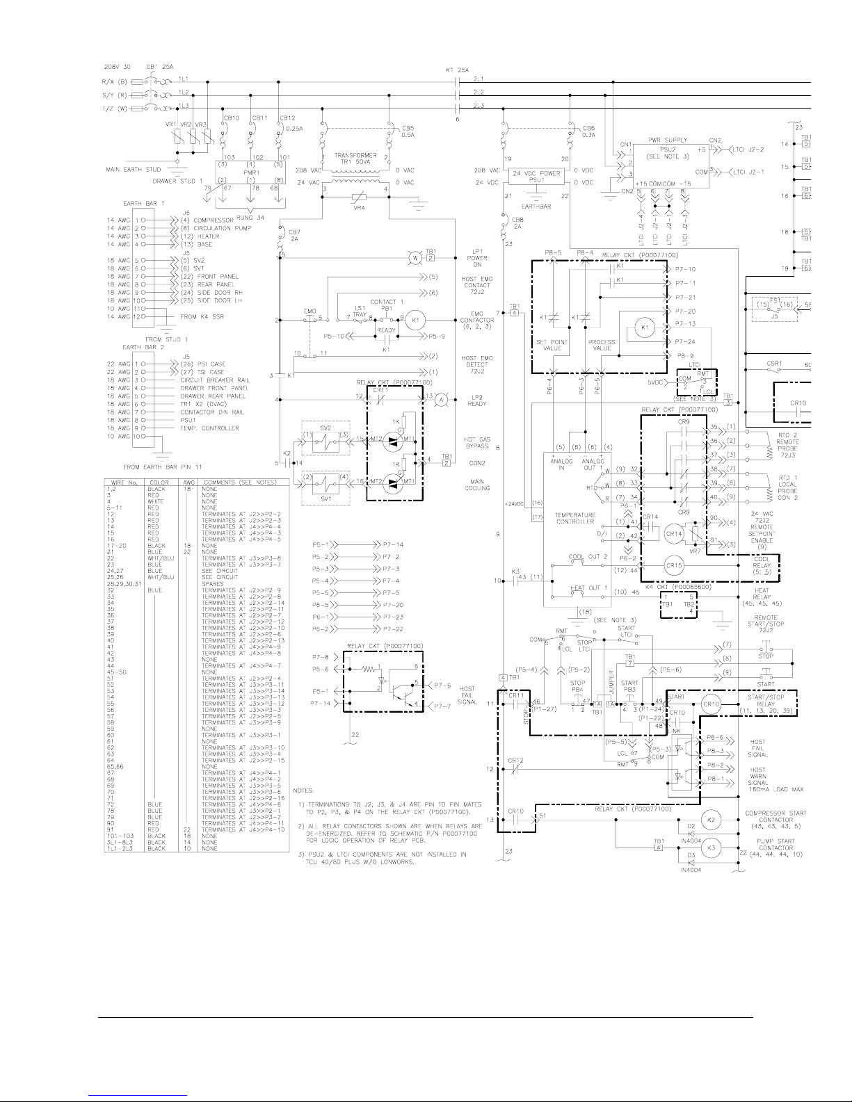
(G:\Technical Documents\MANUALS\W95900011- All)
TCU 40/80 Temperature Control Unit 51
Figure 15 - Electrical Drawer Schematic (Page 1)
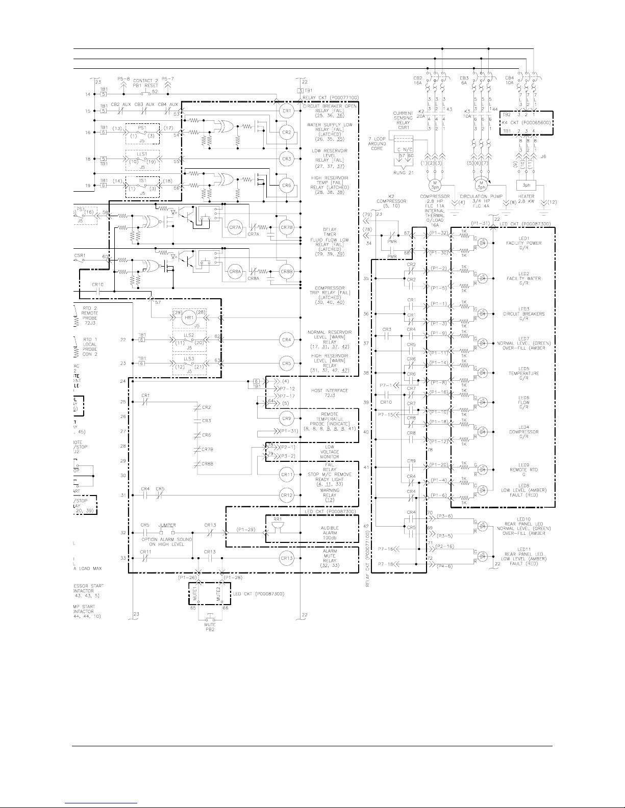
(G:\Technical Documents\MANUALS\W95900011- All)
52 TCU 40/80 plus Temperature Control Unit
Figure 15 - Electrical Drawer Schematic (Page 2)

(G:\Technical Documents\MANUALS\W95900011- All)
TCU 40/80 Temperature Control Unit 53
Figure 16 – Remote Interface

9. Accessories And Spare Parts
Accessories and spare parts are available from service centers at BOC Edwards companies in Brazil,
Canada, Germany, Great Britain, Italy, Japan, USA, and a worldwide network of distributors. The majority
of these centers employ service engineers who have undergone comprehensive BOC Edwards training
courses. When ordering please state for each part required:
· Model and code number of your equipment
· Description of part
· Serial number (if any)
Table 15 - Accessories
Part Number Description Contents Qty
P60150400 Coolant connection kit Ball valve 1/2” female NPT 2
1/2” male connector 4
P60152200 Tie-bolt kit
(Anchors top to bottom unit when
stacking)
P60154600 Stabilization kit
(Anchors bottom or single unit to
floor.)
P60153100 Remote RTD assembly
(auxiliary)
P60188300 Coolant RTD assembly
(external)
P60152100 Leveler kit Leveler pad 4
P30152700 Secondary containment receptacle Removable spill containment system 1
P60141100 Funnel Off-set funnel with Swagelok connector 1
P60153200 Host interface connector kit 9 pin plug (J72J2) 1
P53289800 Fluorinert 11 pound container 1
P53289900 Fluorinert 44 pound container 1
P60153005 Preventative maintenance kit Lamps, 28vac, 60 mA 4
P60140600 Electrical drawer assembly Electrical drawer 1
P60153001 Refrigeration refurbishment kit Filter/dryer 1
P60153003 Electrical refurbishment kit Heater contactor 1
P60153004 Coolant pump rebuild kit Gear shafts 2
P60140301 Coolant pump/motor assembly Coolant pump/motor 1
Rod 3/8”-16 x 7” 4
Hex nut 3/8”-16 4
Flat washer 3/8” 4
UnistrutÒ channel 2
Studs 3/8”-16 x 5” 4
Hex nut 3/8”-16 4
Flat washer 3/8” 4
Lock washer 3/8” 4
100W RTD; 3 wire, 15’ leads 1
5 pin circular connector (J72J3) 1
100W RTD; 3 wire, 15’ leads 1
5 pin circular connector (J72J3) 1
½” X ½” pipe connector 1
Rod 3/8”-16 x 7” 4
Hex nut 3/8”-16 4
Flat washer 3/8” 4
Lock washer 3/8” 4
Sockets (J72J2) 9
37 pin male “D” connector (J72J1) 1
Backshell w/hardware (J72J1) 1
5 pin circular connector (J72J3) 1
Solenoid valve coils 2
Discharge service valve 1
Suction service valve 1
Pump contactor 1
Solenoid valves 2
Lamps 2
Gears (idler & drive) 2
Seals 3
Wear plates 4
Bearings 4
54 TCU 40/80 plus Temperature Control Unit

TCU 40/80 Temperature Control Unit 55

10. OPTIONS
10.1 LonWorks
10.1.1 References
10.1.2 Overall Description
The LTCI is a microprocessor-based system installed in the TCU 40/80 plus chiller unit providing
LonWorks network nodes with access to a number of chiller control and status monitoring points.
When used with Lam processing equipment, the LTCI communicates primarily with a Lam Host Node
using the LonWorks protocol in accordance with the specifications provided in [1]. Figure 17 shows
the overall LTCI architecture.
[1] Lam, CSD5014 V0.1, 300mm Software Requirements Specification for Generic
LonWorks Interface, 21 April 1997
[2] Lam, CSD5139 V0.1, Software Requirements Specification for LonWorks Interface
for the BOC Edwards Chiller, 20 June 1997
[3] Echelon Corporation, The SNVT Master List and Programmers Guide, May 1997
(G:\Technical Documents\MANUALS\W95900011- All)
TCU 40/80 Temperature Control Unit 55
Figure 17 - Overall LTCI Architecture
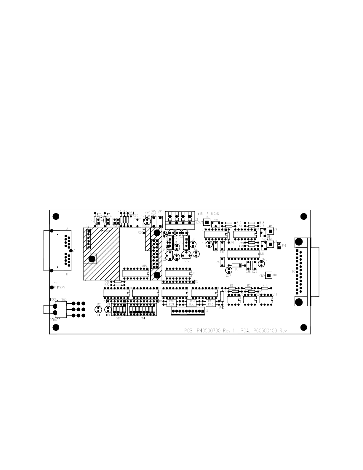
10.1.3 Requirements
1. Physical
The LTCI is configured as two subassemblies: the Interface Module (IM) and the Control Module
(CM). The CM utilizes a standard Echelon twisted pair control module programmed to implement the
control and status monitoring functions. In addition to the NEURON processor and support functions,
the CM provides the LonWorks network interface transceiver, allowing the LTCI to be adapted to
different LonWorks physical media by exchanging the CM. The IM provides recommended
termination loads for both twisted pair and FTT transceiver types with termination selected via
jumpers.
The IM supports 3 functions: (1) conditioning of ±15VDC and +5VDC input power to provide filtered
+5VDC and ±12VDC supply power for digital and analog functions, (2) signal conversion and
conditioning functions to support the analog and digital interfaces between the LTCI processor and
TCU 40/80 plus and, (3) physical connection points supporting the TCU 40/80 plus and LonWorks
network interfaces. The CM plugs into the IM directly as a daughterboard.
2. Size/Weight/Mounting Requirements
The CM and IM functions are implemented as separate modules that are connected together to operate.
The IM supports the physical mounting within the TCU 40/80 plus drawer using three standoffs. The
CM connects to the IM using two connectors: one supporting the LonWorks network interface and one
supporting a digital interface between the NEURON processor circuitry on the CM and the power and
signal conditioning circuitry on the IM. In addition to the electrical connections, the CM is secured to
the IM using threaded standoffs.
Figure 18 shows a preliminary physical layout of the LTCI unit, combining the IM and CM modules.
(G:\Technical Documents\MANUALS\W95900011- All)
56 TCU 40/80 plus Temperature Control Unit
Figure 18 - LTCI Physical Layout

3. Address and Subnet Switch Settings
The LonWorks PCB has two DIP switches SW3 and SW4. Switch SW3, which has four switches, is
the Subnet Switch. When the switches are in the CLOSE position, their value is 0. When they are in
the OPEN position, their values from right to left are 1, 2, 4 and 8.
Open
SW3
4 3 2 1
8 4 2 1
values
The Subnet Switch default value is set at 2. Therefore switch 2 is in the open position. If SW3 is to be
set at 3 then switch 1 and 2 should be in the OPEN position (1+2 = 3).
If SW3 is to be set at 5 then switch 1 and 3 should be in the OPEN position (1+4 = 5).
Switch SW4, which has 8 switches, is the Address Switch. When the switches are in the CLOSE
position, their value is 0. SW4 address, when all the switches are in the CLOSE position, is 65. When
they are in the OPEN position, their values from right to left are 1, 2, 4, 8, 16, 32, 64 and 128. The
lowest address value that SW4 could be set at is 65 and highest address is 95.
Open Open
SW4
8 7 6 5 4 3 2 1 8 7 6 5 4 3 2 1
128 64 32 16 8 4 2 1
Open
4 3 2 1
SW3 set to 2
values SW4 set to 70
The Address Switch default value is set at 70. Therefore switch 1 and 3 are in the open position
(65 + 1 + 4 = 70)
If SW4 is to be set at 85 then switch 3 and 5 should be in the OPEN position
(65 + 4 + 16 = 85).
If SW4 is to be set at 95 then switch 2 through 5 should be in the OPEN position
(65 + 2 + 4 + 8 + 16 = 95).
4. Power Requirements
The LTCI requires a constant supply of ±15VDC & 5VDC at J2 for use as primary power. From this
primary power source, the IM power conditioning circuitry provides the LTCI with two filtered DC
voltages, +5VDC and +12VDC to support the signal conditioning and conversion functions.
5. General/Environmental Requirements
Physical Parameter Limits
Operating Temperature +10C to +50C
Humidity 80%
TCU 40/80 Temperature Control Unit 57

ETC Output
(Process Temp.)
6. Functional Requirements
The LTCI supports the following TCU 40/80 plus control and monitoring functions:
1. Temperature Monitoring/Control
2. Start/Stop Control
3. Status Monitoring
The functional requirements associated with each of these capabilities are described in detail below.
LTCI operation involves communication with the Lam Host Node using LonWorks network variables
(NVs) and the following descriptions make a number of references to these NVs.
7. TCU 40/80 plus Temperature Monitoring/Control
The LTCI interfaces with the analog input and output interfaces of TCU 40/80 plus’s embedded
temperature controller (ETC), allowing it to specify the process temperature setpoint and monitor the
current process temperature respectively. Each of these analog interfaces uses a ±10V signal to linearly
represent temperature in accordance with the specifications given in Table 16. During operation the
LTCI samples the ETC voltage output, convert it to temperature, and, and transmit it to the Lam Host
Node via the LonWorks interface in accordance with the protocol described in [1] and [2]. Table 16
specifies the process temperature-sampling rate used by the LTCI.
Table 16 - Analog Temperature Signal Characteristics
Signal Sampling/Update
Rate
ETC Input
(Temp.
Setpoint)
Updated upon receipt
of value from Lam
Host
Sampled at 1S period Linear Mapping:
Voltage/Temperature
Conversion
Linear Mapping:
±10VDC => ±100°C
±10VDC => ±100°C
Notes
Sent to Lam Host as described in Text in
accordance with host update and deadband
specification.
Although the process temperature is sampled at regular intervals, not every sample is transmitted to the
host. The LTCI provides two methods of limiting the rate of the temperature updates that it receives:
1. Specification of a minimum update period by the host using the nviNodeConfig network
variable
2. Implementation of a temperature update deadband of ±1° C.
The minimum update period specifies the minimum amount of time that must transpire between
temperature updates. The LTCI ensures that temperature updates are not sent more frequently than
the time specified by the minimum update period.
The temperature update deadband specifies the minimum temperature change between host
updates. The current process temperature must differ from the last host update by more than the
amount specified by the update deadband in order for the LTCI to send it to the host. This function
prevents the host from receiving unnecessary updates indicating identical temperatures or very
small temperature changes. In order to provide the host with reasonably fresh process data, the
LTCI ensures that a temperature update is sent to the host within at least 10 minimum update
periods regardless of whether it exceeds the specified deadband.
The TCU 40/80 plus may be operated in either Local Mode or Remote Mode, with selection made
manually via a rear panel switch. The LTCI commands the TCU 40/80 plus to use either the local
or remote temperature probes in accordance with the switch setting through connection to the TCU
40/80 plus’s Host Interface contacts controlling relay CR9. The network variable used to send the
process temperature to the host, nvoData, will contain a flag indicating the temperature
measurement source as well as the temperature.
The LTCI will also be capable of commanding the TCU 40/80 plus to utilize either a Local or
Analog Setpoint specification using the D/I interface of the ETC, replacing the functionality of
CR14. The Local Setpoint is fixed and preprogrammed into the ETC, whereas the Analog Setpoint
is generated by the LTCI in accordance with the temperatureSetpoint member of the
nviConfig network variable, specified by the Lam Host Node. Upon receipt of an update to the
nviConfig network variable, the LTCI sets its Analog Setpoint output in accordance with the
specified temperature value without regard to the status of the temperatureSetpoint
member. If temperatureSetpoint indicates selection of the Analog Setpoint, the LTCI
ensures that the Analog Setpoint value is updated prior to selecting it.
58 TCU 40/80 plus Temperature Control Unit

On initial Power-up, prior to receiving a setpoint specification from the host, the LTCI will
command a default setpoint of 25° C.
8. TCU 40/80 plus Start/Stop Control
The LTCI provides the Lam Host Node with the ability to start and stop chiller operation using the
nviControl network variable. This is accomplished through connection to the TCU 40/80 plus
Remote Start/Stop interface.
9. TCU 40/80 plus Status Monitoring
Note: The specific TCU 40/80
plus
status monitoring functions have not been finalized. The description
contained within this section presumes the desire to monitor a variety of status conditions through
connection to the status indicator panel at connector P1. Alternatively, TCU 40/80
plus
status
indications could be limited to the Host Fail and Host Warning indications.
The LTCI provides the Lam Host Node with the ability to monitor a variety of TCU 40/80 plus status
conditions. The LTCI monitors TCU 40/80 plus status through connection to the TCU 40/80 plus Status
Indicator Panel connections within the TCU 40/80 plus drawer. In supporting these connections, the
LTCI ensures that it does not present an excessive load to the panel drivers and will not affect the
intensity of the existing LED displays.
The LTCI will poll the following status monitoring signals at the same time that it samples chiller
temperature:
1. Host Fail Signal
2. High Reservoir Temperature
3. Local Mode
4. Low Reservoir Level Warning
5. Low Reservoir Level Fail
6. Low Fluid Flow Fail
Each of these conditions, except for Local Mode, will be mapped to a bit in the error_codes
member of the nvoStatus network variable. In accordance with the protocols specified in [1] and
[2], nvoStatus is sent to the Lam Host node upon receipt of an update to the nviHeartbeat
network variable containing the LTCI node address or whenever there is a change in TCU 40/80 plus
status.
If the Lam host issues a TCU 40/80 plus control command (START/STOP, Temperature Setpoint, or
Temperature Alarm Setpoint) while the TCU 40/80 plus is in Local Mode, the LTCI will set the Local
Mode bit within error_codes and send nvoStatus to the host.
10.1.4 Interfaces
1. LonWorks Interface
a. Physical Network Interface
The LonWorks network interface is provided on the LTCI CM utilizing a standard,
transformer-coupled 1.25Mbps twisted-pair transceiver sold by Echelon Corporation (PN
50020-10). The transceiver supports connection to other approved 1.25Mbps transceivers,
using standard signaling levels and power-down protection mechanisms. The LTCI will
connect the output of the CM transceiver directly to the network interface. The transceiver
output is transformer-coupled interface to the network, thus providing electrical isolation.
The LTCI will provide the ability to select one of three types of LonWorks network
termination circuits through jumpers: (1) Twisted Pair bus termination, (2) FTT Bus
Termination, and (3) FTT Free Topology Termination. Selection of a Termination Circuit
is not required.
TCU 40/80 Temperature Control Unit 59

b. Interface Protocol
The LTCI LONW
ORKS
interface communicates with the Lam Host node through the
exchange of messages using LonWorks Network Variables (NVs). Each NV contains one
or more parameters, is defined using a C syntax to include any valid C data type (i.e., ints,
structures, enums, etc.), and is declared as either an input or output. In order to transmit a
message to the host, the LTCI will update an associated output NV, causing the embedded
LonTalk protocol stack to generate a message by adding appropriate addressing and
message delivery information. The addressing will specify delivery to a corresponding
input NV at the Lam Host node. Upon receipt of the message, the protocol stack at the
host node will unpack the message to produce an update to the selected input NV.
Communication from the Lam Host to the LTCI is handled identical.
The LTCI provides a set of network variables to meet the basic network interface
requirements specified by Lam in [1] and to support specific TCU 40/80 plus control and
monitoring functions described previously. Host control of TCU 40/80 plus operation is
performed by writing to Host output network variables that are mapped to associated LTCI
input network variables. Upon detection of a network variable update, the LTCI firmware
translates the input network variables into corresponding TCU 40/80 plus commands.
TCU 40/80 plus status is continuously monitored by the LTCI and is provided to the
LonWorks interface by updating the values of appropriate output network variables in
accordance with the protocol described by Lam in [1].
Table 18 defines the set of network variables implemented by the LTCI. Input network
variables are sent from the host node to the LTCI and are named with an “nvi” prefix.
Input network variables having their contents to be saved in nonvolatile EEPROM are
named with an “nci” prefix. Output network variables are sent from the LTCI to the host
node and are named with an “nvo” prefix. The LTCI firmware declares the network
variables in the same sequence as shown in Table 18 and will use the self installation
procedures described in [1] to assign the associated network variable selectors as
indicated.
60 TCU 40/80 plus Temperature Control Unit

Table 17 - LTCI Network Variables
3: This nviHeartbeat definition is taken from the Lam SRS for the BOC Edwards Chiller
[2].
Network
Variable
nviHeartbeat uint
Type Selector Function Notes
2,3
0 Specifies address of node to
Per Lam Specification
respond with a nvoStatus update
nvoStatus status_struct1 1 Contains node status info:
last reset cause
heartbeat acknowledgment
HW FAIL flag
Per Lam Specification
Chiller error codes adapted from
Lam specification. See text for
description
COMM FAIL flag
HEARTBEAT FAIL flag
Chiller errors
nviNodeConfig nodeconfig_struct1 2 Specifies minimum update
Per Lam Specification
period, heartbeat time-out, and
contains output force flag
nviCommReset uint2 3 Commands a transition from
COMM FAIL state to
NORMAL state
Per Lam Specification
If the LTCI is not in a COMM
FAIL state, this will be ignored
nviHWReset uint2 4 Commands a hardware reset Per Lam Specification
nvoNodeInfo info_struct1 5 Specifies node type and
firmware revision
nciNetConfig SNVT_config_src3 6 Specifies whether node should
Per Lam Specification
For LTCI, node type is 245
Per Lam Specification
perform self-installation
nviControl SNVT_lev_disc 7 Commands TCU 40/80 plus
Start/Stop
BOC Edwards Specification
ST_OFF => STOP
ST_LOW-ST_ON => START
other values are ignored
nviConfig config_struct1 8 Specifies LTCI/Chiller operating
BOC Edwards Specification
configuration:
LTCI Analog Setpoint
High Temperature Alarm
Setpoint
Low Temperature Alarm
Setpoint
nvoData data_struct1 9 Contains current coolant
Adapted from Lam Specification
temperature and measurement
source
Notes:
1: NEURON C structure definitions are contained in Appendix A.
2: Lam Specification defines these as unsigned short (8 bits). unit represents an unsigned, which NEURON C represents
as 8 bits.
c. Network Variables
This section describes the network variables provided by the LTCI. It should be
remembered that the input/output sense of these NVs is defined in reference to the LTCI
node.
nviHeartbeat
This input NV contains a Lam network node address and is broadcast periodically by the
Lam host node to the entire subnet to determine the status of the network nodes. Upon
receipt of the nviHeartbeat message, the LTCI will reset its local heartbeat timer and
compare the supplied node address to its own node address. The LTCI node address is
determined by reading the state of a 6-bit DIP switch contained on the LTCI module
during power-up reset. If the addresses match, the LTCI will transmit the nvoStatus
NV to the host.
TCU 40/80 Temperature Control Unit 61

nvoStatus
The nvoStatus NV contains the status information shown in Table 18. It is sent to the
Lam Host node in response to receipt of a nviHeartbeat message containing the LTCI
address and in response to a NEURON chip watchdog time-out.
Table18 - Definition of nvoStatus Network Variable
Status Parameter Meaning Notes
Reset Cause A 4-bit indication of the cause of the last LTCI reset:
0 => Power-up Reset
1 => External Reset
2 => Watchdog Reset
3 => Software Reset
If reset is due to a watchdog timeout, the LTCI will forward the
nvoStatus NV to the Lam Host at
the end of reset processing. All
other reset conditions will simply
be saved for subsequent
transmission in response to
heartbeat polls or other status
changes
Heartbeat
Acknowledgment
A single bit acknowledgment to a heartbeat poll. Only set for heartbeat
acknowledgments
Flag
Hardware Failure
Flag
A single bit set to indicate an LTCI or TCU 40/80 plus
hardware failure
Any hardware failure will result
in immediate transmission of
nvoStatus. The flag will be
cleared upon removal of the
hardware fault condition.
Communication
Failure Flag
A single bit set to indicate an LTCI LonWorks
communication failure
Any communication failure will
result in immediate transmission
of nvoStatus. This flag will not be
reset until the LTCI receives
nviCommReset having a value of
“1”
Heartbeat Failure
Flag
A single bit set to indicate that the LTCI heartbeat timer
has timed out.
Detection of a heartbeat time-out
will not result in transmission of
nvoStatus. The flag will be
cleared upon detection of the next
heartbeat poll input.
TCU 40/80 plus
Error Codes
A set of 8 bits indicating TCU 40/80 plus status:
Bit 0: TCU 40/80 plus High Reservoir Temp. Fault
Bit 1: TCU 40/80 plus Low Fluid Flow Fault
Bit 2: TCU 40/80 plus Local Mode
Bit 3: TCU 40/80 plus Low Reservoir Level Fault
Bit 4: TCU 40/80 plus Low Reservoir Level Warning
Bit 5: TCU 40/80 plus Temperature below Lo Temp Alm
Setpt.
Bit 6: TCU 40/80 plus Temperature above Hi Temp Alm
Detection of any Fault condition
will result in immediate
transmission of nvoStatus.
Detection of any Warning
condition will not result in
immediate nvoStatus
transmission.
“0” indicates No Fault
“1” indicates Fault
Setpt.
Bit 7: TCU 40/80 plus System Status (Summary Fault)
nviConfig
The nviConfig NV contains three parameters:
1. The minimum period between LTCI temperature updates (in milliseconds)
The LTCI transmits TCU 40/80 plus temperature updates to the host whenever the
temperature changes by an amount greater than the update deadband, but will not
transmit at a rate faster than that specified by the minimum update period.
2. The Heartbeat time-out period (in seconds)
The LTCI will immediately reset the heartbeat timer to the value specified. If the timer
expires before the next heartbeat message is received, then the LTCI will declare a
heartbeat fault.
3. The output condition force flag
If the output condition force flag is set, the LTCI will set the analog and discrete output
signals to default conditions.
62 TCU 40/80 plus Temperature Control Unit

nviCommReset
The LTCI will verify the successful transmission of each message from itself to the Lam
Host as specified in [1]. Upon detection of a communication failure the LTCI will enter the
COMM FAIL state and remain there until it receives an nviCommReset message having
a value of “1”. Upon receiving such a message, the LTCI will exit the COMM FAIL state
and enter the NORMAL state. If the LTCI is in the NORMAL state it will not take any
action upon receipt of a nviCommReset message.
nviHWReset
Upon receiving a nviHWReset message having a value of “1”, the LTCI will initiate a
hardware reset of the TCU 40/80 plus by pulsing the reset relay.
nvoNodeInfo
The nvoNodeInfo NV contains the LTCI node type specification and current LTCI
firmware revision and is used by the Lam host to identify the individual nodes within the
300 mm system. The LTCI will report the node type as 245 and will report the software
revision using the format X.YZ where X is the major version number and YZ are minor
version numbers.
nciNetConfig
The nciNetConfig NV specifies whether the LTCI will perform self-installation
functions. nciNetConfig is an enumerated Standard Network Variable Type (SNVT)
and may have values of CFG_LOCAL (“0”), CFG_EXTERNAL (“1”), or CFG_NUL
(“FF”). When reset, the LTCI firmware will read the value of the nciNetConfig NV. If the
value is CFG_LOCAL, the LTCI will perform the self installation procedures specified in
[1] to assign its own domain, subnet, and node address parameters and set up the address
table used to communicate with the Lam Host node. If the value is not CFG_LOCAL, the
LTCI will not perform any self-installation processing.
nvoData
1. The nvoData NV indicates the most recent TCU 40/80 plus temperature measurement
and the measurement source (local or remote). Temperature will be specified in degrees C
above -273°C with a resolution of 0.1°C in accordance with the NEURON C SNVT_temp
network variable type definition. The measurement source will have a value of either “0” or
“1”. A “0” will indicate a local measurement and a “1” will indicate a remote measurement.
The nvoData NV will be sent whenever the measured temperature has changed by greater
than the specified temperature deadband.
For Condition 1, the LTCI will ensure that temperature updates are not transmitted with a
period of less than that specified in the nviConfig NV. For both conditions, the LTCI
will adjust the deadband to coincide with the most recently transmitted temperature.
nviConfig - Specifies the LTCI/Chiller operating configuration
The nviConfig NV is used by the Lam Host node to specify LTCI and TCU 40/80 plus
operating parameters. nviConfig specifies the following LTCI and TCU 40/80 plus
operating parameters:
1. LTCI Analog Setpoint Specification
2. High and Low Temperature Alarm Setpoints
nviControl
The nviControl NV is used to start and stop chiller operation. It utilizes the standard
NEURON C enumerated type of SNVT_lev_disc for a two-state device, using ST_OFF
to specify Chiller Stop. Receipt of any of the following specify Chiller Start: ST_LOW,
ST_MED, ST_HIGH, ST_ON. All other values will be ignored.
TCU 40/80 Temperature Control Unit 63

TCU 40/80 plus Interface
LTCI Power Interface
The LTCI will require ±15VDC and +5VDC at CB1 for use as primary power. Power
conditioning circuitry onboard the LTCI will re-regulate this to provide +5VDC and
±12VDC for use by the LTCI circuitry. The LTCI will not separately fuse the input
power.
Analog Output Interface
Using a D/A and appropriate signal conditioning circuitry, the LTCI Analog Output
Interface will be capable of generating output voltages between -10VDC and +10VDC
into a 100KΩ load. The accuracy of the analog output will be 0.2% or better over the
LTCI operating temperature range. The maximum analog update rate will be 10 updates
per second.
Analog Input Interface
The LTCI Analog Input Interface will be capable of measuring analog input signals
between -10VDC and +10VDC to a resolution of 12 bits. It will present a load of no less
than 100KΩ to the analog driver circuit. The LTCI A/D will incorporate appropriate
sample and hold functions to ensure accurate conversion in the presence of changes in
input signal amplitude during conversion. The maximum A/D sampling rate will be 10
samples per second.
Contact Closure Interface
The LTCI will utilize solid-state devices to support all contact closure outputs. The
selected devices will provide a closed contact resistance of less than 30Ω. The LTCI will
be electrically coupled with the TCU 40/80 plus circuitry through its use of the same
24VDC and return that is used to support TCU 40/80 plus circuitry and its transformercoupled isolation from the LonWorks Twisted Pair network. The LTCI contact closure
interfaces will utilize optical isolation circuitry.
0/24VDC Interfaces
The LTCI will detect the state of the TCU 40/80 plus status monitor signals through
direct coupling to the TCU 40/80 plus circuits that are used to drive the status indicating
LEDs. The LTCI detection circuitry will provide input impedance of at least 10KΩ to
avoid any degradation in indicator performance. All of the 0/24VDC status signals are
uniquely mapped to fail-safe conditions. For these signals, absence of a 24VDC-signal
level is an indication of the associated fault.
The TCU 40/80 plus uses relay ladder logic to implement the Reservoir fluid level
warning and failure indicators, precluding the simple detection of the associated fault
conditions. The LTCI will combine the detection of the two Low Reservoir Level signals
to detect the Fail and Warning conditions as follows:
Reservoir Level Warning = A & B
Reservoir Level Fail = !A & B
Reservoir Level Normal = A & !B
where:
A = TCU 40/80 plus P7-16
(TCU 40/80 plus Reservoir Normal Indication)
B = TCU 40/80 plus P7-18
(TCU 40/80 plus Reservoir Fail Indication)
Electrical Interconnections
The electrical connections between the LTCI and the TCU 40/80 plus are shown in Figure
22.
64 TCU 40/80 plus Temperature Control Unit

Rear Panel
Figure 18 shows the rear panel. Table 19 identifies the controls and indicators on the rear
panel.
Figure 19 - Electrical Rear Panel
(G:\Technical Documents\MANUALS\W95900011- All)
Table 19 - Description of Rear Panel Components and Indicators
Label Description
J72J3 Five-pin connector for remote RTD interface. See figure 16 on page 59 for
pinouts.
CB7 24 VAC 1-pole, 2 Amp circuit breaker. Isolates the 24 VAC transformer. Normally on
(in).
CB8 24 VDC 1-pole, 2 Amp circuit breaker. Isolates the 24 VDC power supply output.
Normally on (in).
J72J2 Nine pin connector for remote EMERGENCY OFF, start-stop operation, and
remote setpoint operation enable. See figure 16 on page 59 for pinouts.
CB4 reservoir heater 3-pole, 10 Amp circuit breaker. Normally on (up).
CB3 circulation pump 3-pole, 6 Amp circuit breaker. Normally on (up).
CB2 compressor 3-pole, 16 Amp circuit breaker. Normally on (up).
CB1 main power 3-pole, 25 Amp circuit breaker. Normally on (up).
normal/overfill Normal, LED Green
Overfilled, LED Amber
low/fault
200/208 VAC 3 PH
50/60 Hz 30A
CB5-XFMR 2-pole, 0.5 Amp circuit breaker. Isolates the equipment transformer.
CB6-PSU 2-pole, 0.3 Amp circuit breaker. Isolates the power supply.
LonWorks Local/Remote Switch
RJ-45 connectors for LonWorks communications
Low, LED Amber
Fault, LED Red
Mains input power connector.
TCU 40/80 Temperature Control Unit 65
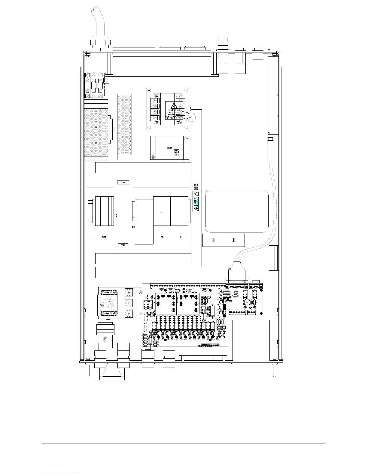
B
C
P
S
K
R
O
W
N
O
S
R
E
T
L
I
F
C
A
L
PSU2
PHASE
MONITOR
RELAY
PSU1
K3
TB GND
CB10CB10
CB12CB12
TB2
(G:\Technical Documents\MANUALS\W95900011- All)
66 TCU 40/80 plus Temperature Control Unit
Figure 20 - Electrical Drawer LonWorks

No Text
TCU 40/80 Temperature Control Unit 67

(G:\Technical Documents\MANUALS\W95900011- All)
68 TCU 40/80 plus Temperature Control Unit
Figure 21 - Electrical Drawer Schematic

(continued …..) Figure 21 - Electrical Drawer Schematic
(G:\Technical Documents\MANUALS\W95900011- All)
TCU 40/80 Temperature Control Unit 69

(G:\Technical Documents\MANUALS\W95900011- All)
70 TCU 40/80 plus Temperature Control Unit
Figure 22 - Remote Interface
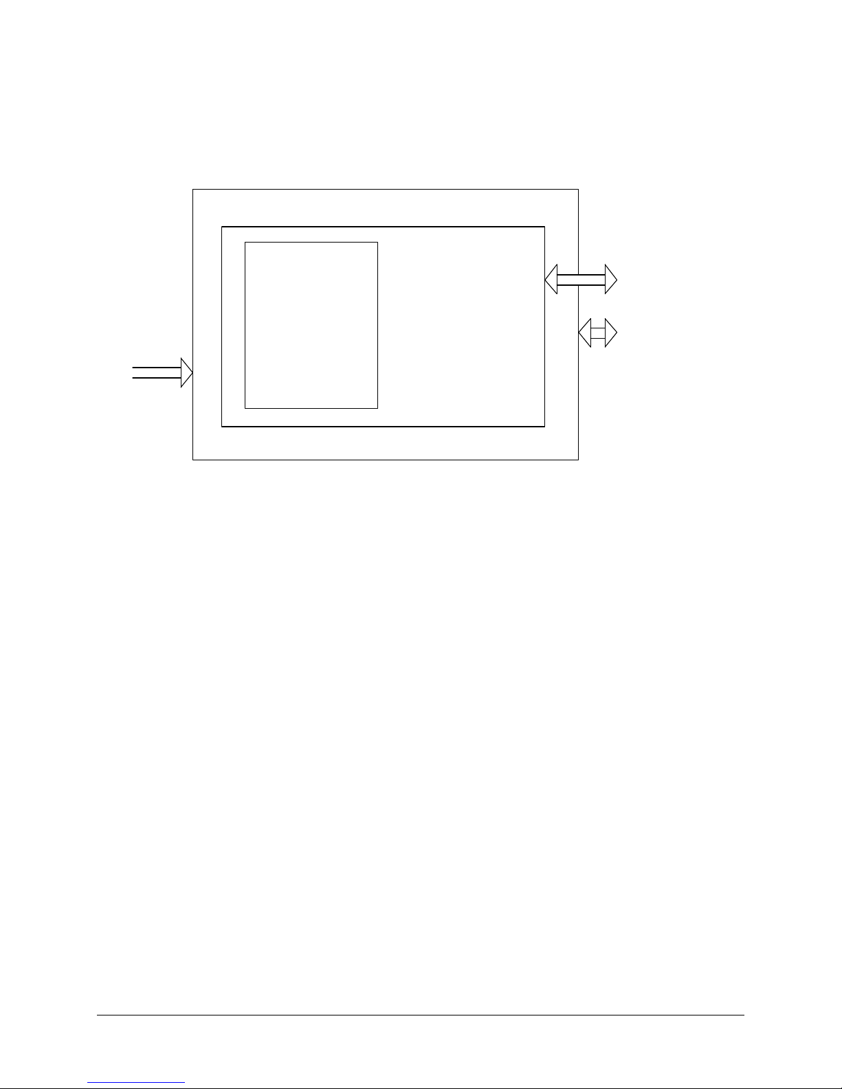
10.2 RS 232 TEL
FIG 23
10.2.1 Block Diagram
The signals comprises contact I/O signals and an RS-232C communication function.
See Figure 23.
DIGITAL I/O
ANALOG I/O
9 WAY
[RS 232C]
D SUB
A - D
CPU
15 WAY
D SUB
[HOST CONTROL I/O SIGNALS]
INTERFACE
BLOCK DIAGRAM
(G:\Technical Documents\MANUALS\W95900011- All)
10.2.2 Operation Modes and Contents of Function
The modes include local operation mode and remote operation mode. The Functions available
differ in each mode.
1. Local operation mode
In this mode of operation, the TCU can only be controlled from the front control panel.
System status and Process Temperature maybe monitored by the external host device. In the
case of power shut down, the set point will default to 25°C upon the next system power up.
2. Remote operation mode
In this mode the unit can be operated by a signal generated from the external host device.
“Run” and “Stop” of the unit, temperature set point is only available from the external host
device.
Note: The alarm may only be reset at the front control panel of the TCU.
3. Set point retention during mode switching
If the unit is switched from Local to Remote operation, the temperature set point will be set
by the external host device. If the unit is switched for Remote to Local operation, the
temperature set point will be set by the last value retained in the temperature controller.
4. Available functions in each mode
The functions available in each mode are listed in Table 20
TCU 40/80 Temperature Control Unit 71

Table 20 – Available Functions
Operation At the TCU At the Host RS-232
Local operation
Run C M M
mode
Stop C M M
Temperature Setting C M M
BAND Setting M M M
Alarm reacting C ----------------- --------------
-----
Reading of set
C (with display) M C
temperature
Reading of BAND set
value
Reading of process
M (with
M C
display)
C (with display) M C
temperature
Reading of Status C (with display) M C
Remote operation
Run M C C
mode
Stop M C C
Temperature setting M M C
BAND setting M M C
Alarm reading C --------------- --------------
--
Reading of set point
C C C
temperature
Reading of BAND set
M M C
value
Reading of process
C (with display) C C
temperature
Reading of status C (with display) C C
C: Control M: Monitor
Additional description of the functions and terms used in Table 20
1. Band
The term denotes the range between the upper limit and the lower limit of the
temperatures corresponding to the generation of a “TEMPERATURE OK” message and
signal. It can be set over a range of from + 0.5 °C to + 5.0°C. The setting is done only
on the positive side, the negative side is automatically set.
Example: When the set value of BAND is selected to 1.0°C, the message
“TEMPERATURE OK” and a signal is generated when the process temperature
becomes within a range from –1.0°C to +1.0°C of setting temperature.
2. Temperature Ok
When the process temperature enters into the BAND range during operation of the unit,
the message “TEMPERATURE OK” appears on the screen of the Control Display Panel
and signal is generated at the same time. If an offset has been set, the temperature range
of “TEMPERATURE OK” (BAND) adopts the offset display temperature.
72 TCU 40/80 plus Temperature Control Unit
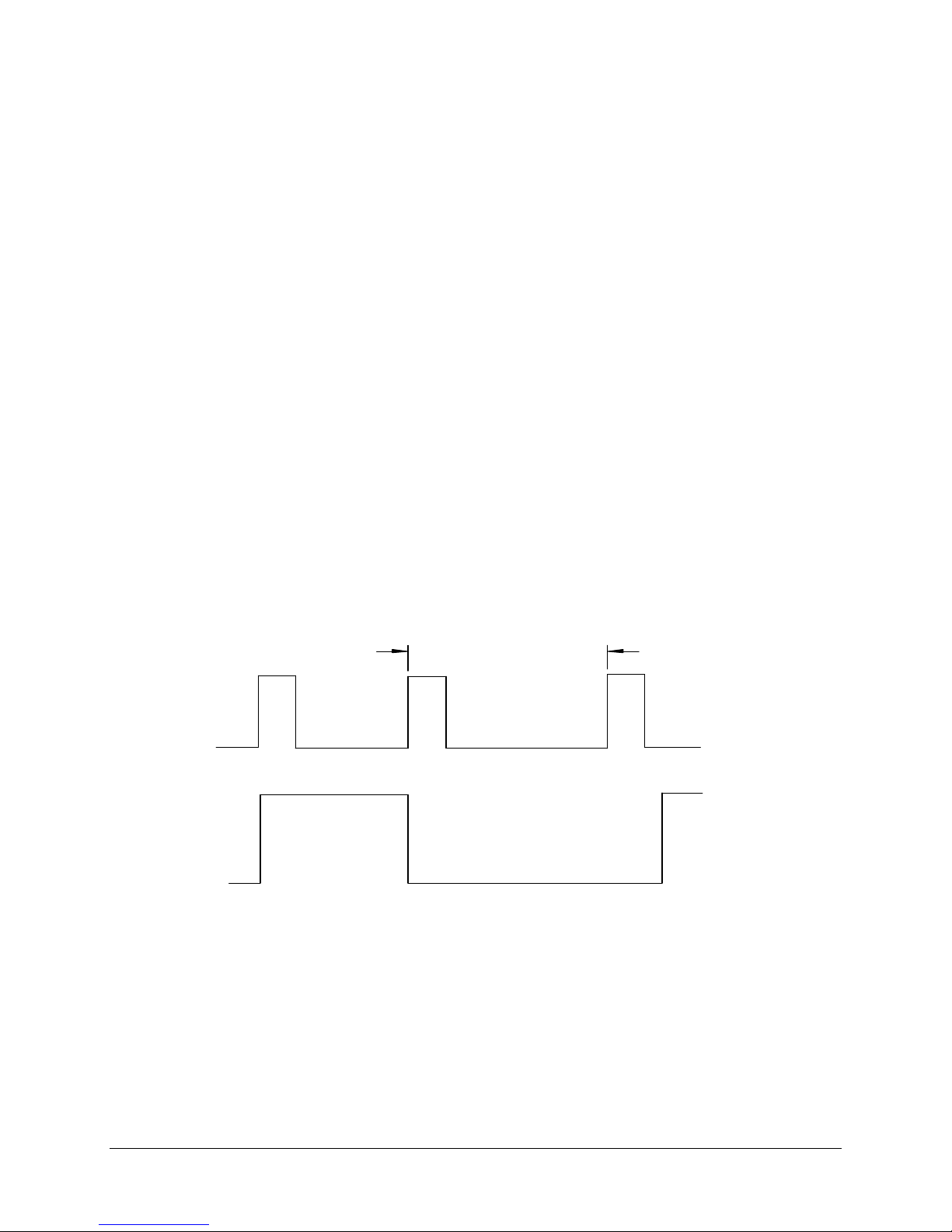
10.2.3 Description of External Control and Monitoring Signals
Two methods of communication are used together, these are:
1. Contact I/O Signals
2. RS 232 Communication
A. Contact I/O Signals
1. Host control signals (Signals to and from an external host device to the TCU)
a. “Run” / “Stop” Signal
2. Monitoring signals (Signals from the TCU to an external host device)
a. “Operation mode” signal (remote operation mode/local operation mode)
b. “Run” Signal
c. “Stop” Signal (Not Used)
d. “TEMPERATURE OK” signal
e. “Fault” Signal (TCU will shut down)
f. “Warning” Signal (TCU will continue to operate)
g. “EMO” Signal
A description and the functions of the contact I/O signals are as follows:
Host control signals (Signals to and from the external host device)
1. “Run” / “Stop” Signal
In remote operation mode, a momentary signal with contact ON (close)
Initiates “Run” and “Stop” of the specified channel in the unit.
S I G N A L
U N I T
M O R E T H A N 3 M I N U T E S
O N
O F F
R U N
S T O P
F I G 2 4 - " R U N " / " S T O P " S I G N A L
(G:\Technical Documents\MANUALS\W95900011- All)
3. Input signal state (common to all signals)
a. The input signals shall be momentary (instantaneous) work mode.
b. The input time shall be set as illustrated below.
TCU 40/80 Temperature Control Unit 73

SIGNAL
BETWEEN 100 [MSEC]
AND 1 [SEC]
ON
OFF
Fig 25 - Control Signal State
(G:\Technical Documents\MANUALS\W95900011- All)
c. Input impedance: 3.0 kΩ
Host monitoring signals (Signals from the TCU to an external host device)
1. “Operation mode” signal
When in remote operation mode, the contact is set to ON.
In local operation mode, the contact is set to OFF.
2. “RUN” signal
The contact is ON (for each channel) during operation
3. “STOP signal (Not Used)
The contact is ON (for each channel) during stop.
4. “TEMPERATURE OK” signal
When the recirculating fluid temperature is within the range of BAND,
the contact is set to ON (for each channel).
5. “FAULT” signal (impossible to sustain operation)
If a major system fault occurs that is likely to cause damage to the TCU,
Host, or endanger life, then the TCU will stop, setting the contact to the
ON position (for each channel).
6. “WARNING” signal (possible to sustain operation)
If a system fault occurs that will not cause damage to the TCU, Host, or
endanger life, then the TCU will continue to operate, setting the contact
to the ON position (for each channel).
7. “EMO” signal
If the emergency stop switch on the operation panel of the unit is
pressed, the power to the unit is shut off and EMO signal is set to OFF
(open).
Note: The capacity of the output signals:
• Contact closure (solid state) capacity of 100 (ma) at 50 volts DC
• The unit shall be operated within the above-specified range Operation
outside of this range may damage the unit.
• All warning & fault signals can only be reset on the unit and cannot be
reset from an external device.
74 TCU 40/80 plus Temperature Control Unit

NC
Table 21 - Pin Assignments at the TCU Host Connection (15 way D sub)
Pin # Function/Use Comment
1 Operation Mode Isolated Solid State
2 Operation Mode Return Contact Closure
3 Run Contact Closure to Common
4 Stop (Not Used) Contact Closure to common
5 Fault Contact Closure to common
6 Warning Contact Closure to common
7 Temperature OK Contact Closure to common
8 Run/Stop Input Command Contact closure to common to
Toggle Run/Stop
9 System Status Common (return) 24 volt Common
B. RS-232C Communication
1. Outline of RS-232C communication functions
RS-232C communication provides the following functions.
a. Reading of data
• Reading of set temperature
• Reading of BAND set value
• Reading of process temperature
• Reading of status
b. Writing of data
• Writing of set temperature
• Writing of BAND set value
NOTE: For Dual Channel operation the signals are independent in each channel
except for the “operation mode” signal. The RS-232C port is also
independent for each channel.
2. Pin Assignment for RS-232C communication connectors
• Connector No. (TBA): for channel 1 (CH1) RS-232C communication
• Type of connector: D-sub 9 pin, socket (female connector)
• Pin assignment for connectors see Figure 24.
TX
RX
GND
TCU 40/80 TELHOST
1
2
3
4
5
6
7
8
9
1
2
3
4
5
6
7
8
9
1
2
3
6
1
2
3
6
SD
RD
SG
9 PIN “D” 9 PIN “D” 9 PIN “D” 9 PIN “D”
FEMALE MALE MALE FEMALE
Fig. 26 - Pin Assignment for TCU-Tel Cable
(G:\Technical Documents\MANUALS\W95900011- All)
NOTE: A Personal Computer with appropriate software can be used to simulate a Host. In this
case a Pin1 to Pin 1, 9 Pin male to female cable can connect the TCU to the P.C.
TCU 40/80 Temperature Control Unit 75

3. RS-232C Specifications
• Standard---------------------------------------------------------RS-232C (EIA)
• Communication Method-------------------------------------Half-Duplex
• Synchronous Type---------------------------------------------Start-stop
• Baud Rate-------------------------------------------------------9600bps
• Character Code-------------------------------------------------ASCII
• Parity------------------------------------------------------------Non
• Start Bit---------------------------------------------------------1 bit
• Data Length-----------------------------------------------------8 bit
• Stop Bit----------------------------------------------------------1 bit
• Block Check----------------------------------------------------See page 80
4. Description Of Transmission/Reception Of Messages
1. Control Code
Table 22 - Control Code
Control Code ASCII Code Function
STX 02H Start of text
ETX 03H End of text
ENQ 05H Enquiry
ACK 06H Acknowledge
NAK 15H Negative acknowledge
CR ODH Carriage Return
1. Header Code
Table 23 - Header Code
Header Code (Hex) Function
31H Reading/Writing of setpoint
temperature
32
H
34
H
36
H
37
H
38H / 39
3A
H
3B
H
H
Reading/Writing of BAND set value
Reading of process temperature
Reading of Status 1
Reading of Status 2
Run CMD / Stop CMD
Select Remote RTD
Select Local RTD
Note: The external host device has priority of communication. Communication begins from the
host, and the TCU answers to the host. Therefore, a response from the TCU must be
confirmed after transmitting a signal from the host. If there is no response from the TCU
within 3 seconds, the host will transmit the signal again. No data is accepted during the
period of response from the TCU.
76 TCU 40/80 plus Temperature Control Unit

5. Block Check (Frame Check Sequence)
FCS is calculated in accordance with the following steps:
Calculation Procedure
By putting 3 to the head of each value, this translates each byte into its ASCII
Hex code.
Add the target of calculation per byte. This will give a 2-byte answer in Hex,
which will be FCS.
(Follow the following example of calculation.)
STX ETX FCS CR
Target of calculation
The FCS Calculation is the sum of the bytes between, but not including [STX]
to [ETX].
Note: 2BH is the Hex value representing the ASCII code for a + sign.
Example: (Writing of set point temperature 25°C)
STX 31H +25 000 000 ETX FCS CR
STX 31H, 2BH, 32H, 35H, 30H, 30H, 30H, 30H, 30H, 30H, ETX…
Sum = 1E3H
Then, FCS will be [3EH, 33H], that is, 3 is added to the head of each figure of
[E][3] H, the
First place 1 byte. (If A—F are included in the calculation result, it will be 3A--and 3F and
Different from ASCII Code.) Note: The most significant byte is dropped.
In this case, the transmission data will be:
02 31 2B 32 35 30 30 30 30 30 30 03 3E 33 OD
STX Header Date Dummy Code ETX FCS CR
Code
6. Description of the Read Command
a. Reading of Set Temperature
Command format [Transmission from host (external device) to the unit
ENQ Header ETX FCS CR
02
H
31
H
03
H
33
31
H
H
Response format [Response from the unit to the host (external device)
STX Header + 9 9 Dummy Code
02
H
31
H
Set Temp. 30H 30H 30
Dummy Code ETX FCS CR
30
30
H
30
H
03
H
H
* * OD
OD
H
H
H
TCU 40/80 Temperature Control Unit 77

Set Point Temperature Data
2 digits ASCII code with +/- sign (-30°C--+90°C)
Example: +10°C: 2BH, 31H, 30
0°C: 2BH, 30H, 30
-20°C: 2DH, 32H, 30
H
H
H
b. Reading of BAND Set Value
Command format [Transmission from host (external device) to the unit]
ENQ Header ETX FCS CR
05
H
32
H
03
H
33H 32
OD
H
H
Response format [Response from the unit to the host (external device)
Equal Box
STX Header 9 9 9 Dummy code
02
H
32
H
BAND setvalue 30H 35H 30
H
Dummy Code ETX FCS CR
30
H
35
H
30
03
H
* * OD
H
H
BAND Set Value
3 digits ASCII code without +/- sign (0.5°C—5.0°C)
Example: 0.5°C: 30H, 30H, 35
5.0°C: 30H, 35H, 30
H
H
c. Reading of Process Temperature
Command format [transmission from host (external device) to the unit]
ENQ Header ETX FCS CR
05
H
34
H
03
H
33
34
H
H
OD
H
Response format [Response from the unit to the host (external device)]
STX Header + 9 9 9 9 Dummy Code
02
H
34
H
Process Temp 30H 30H 30H 30H 30
H
Dummy Code ETX FCS CR
30
30
H
30
H
30
H
30
H
03
H
* * OD
H
H
Process Temperature Data
4 digits ASCII code with +/- sign (-40.0°C--+100.0 °C)
Example: +90.0°C: 2BH, 30H, 39H, 30H, 30
0.0°C: 2BH, 30H, 30H, 30H, 30
-30.0°C: 2DH, 30H, 33H, 30H, 30
H
H
H
78 TCU 40/80 plus Temperature Control Unit
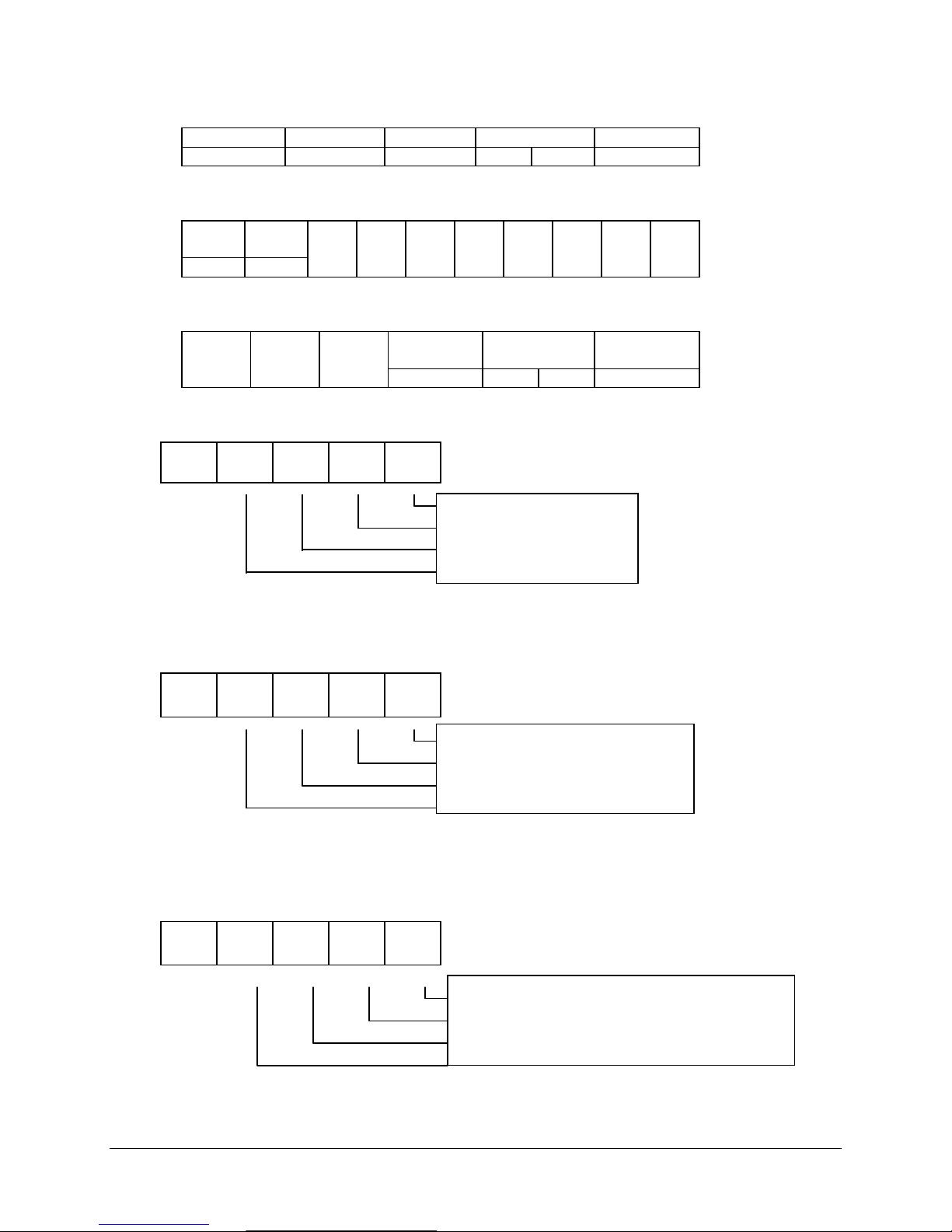
Not used
Not used
Not used
Not used
Not used
Not used
Not used
Not used
Not used
Not used
STX Header
02
H
9
03
1.
3
0011
d. Reading of Status 1
Command format [Transmission from host (external device) to the unit]
ENQ Header ETX FCS CR
05
H
36
H
03
H
33
36
H
H
OD
Response format [Transmission from host (external device ) to the unit]
1
36
H
10
2
11
3
4
5
6
7
ETX FCS CR
H
* * OD
0 0 0 0
(0 fixed)
(0 fixed)
(0 fixed)
(0 fixed)
H
8
H
2.
3
0 0 0
0011
3.
3
0 0 0
0011
“Run” Status (1: RUN 0: STOP)
(0 fixed)
(0 fixed)
(0 fixed)
(0 fixed)
Operation mode status (1: Remote 0: Local)
(0 fixed)
(0 fixed)
TCU 40/80 Temperature Control Unit 79

Not used
Not used
Not used
Not used
Not used
Not used
Not used
Not used
4.
3
0 0
0011
5.
3
0 0
0011
6.
3
0 0 0
0011
Facility Water (a: Fault)
Compressor (1: Fault)
(0 fixed)
(0 fixed)
(0 fixed)
Circuit Breaker (1: Fault)
Low Battery fault (1: Fault)
(0 fixed)
Coolant Temperature Hi (1: Fault)
7.
3
0
0011
Recirculating fluid low level Warning (1: Fault)
Recirculating fluid below low limit fault (1: Fault)
Pump fault/Coolant Flow (1: Fault)
8.
(0 fixed)
(0 fixed)
(0 fixed)
(0 fixed)
80 TCU 40/80 plus Temperature Control Unit
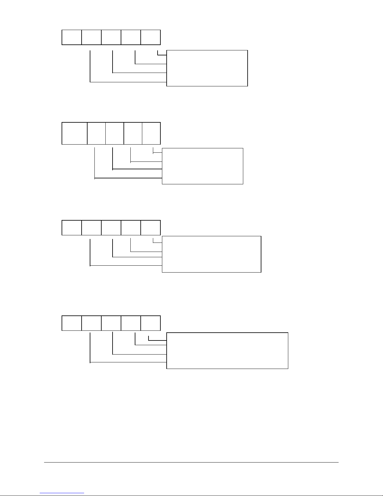
Not used
Not used
Not used
Not used
Not used
Not used
Not used
Not used
Not used
Not used
Not used
Not used
Not used
Not used
3
0 0 0 0
0011
9.
3
0 0 0 0
0011
10.
3
0 0 0
0011
(0 fixed)
(0 fixed)
(0 fixed)
(0 fixed)
(0 fixed)
(0 fixed)
(0 fixed)
(0 fixed)
11.
3
0 0 0 0
0011
(0 fixed)
(0 fixed)
(0 fixed)
Temperature OK (1: Temp OK)
Remote RTD=1 (0 fixed)
(0 fixed)
(0 fixed)
(0 fixed)
TCU 40/80 Temperature Control Unit 81
e. Reading of Status 2
Not used
Not u
Not used
N/A
Not used
Not used
Not used
Not used
Command format [Transmission from host (external device) to the unit]
E
Header ETX FCS CR
NQ
05
H
37
H
03
H
33H 37
H
Response format [response from the unit to the host (external device)]
STX
Header
02
H
37
H
1
2
ETX FCS CR
03
H
* * OD
1.
3
0 0
0011
OD
H
H
3
2.
3
0 0
0011
3.
3
0 0 0
0011
“RUN”/ “STOP signal (1: RUN 0: STOP)
(0 fixed)
sed (0 fixed)
(0 fixed)
Warning signal (1: Warning condition)
Fault signal (1: Fault condition)
(0 fixed)
(0 fixed)
82 TCU 40/80 plus Temperature Control Unit
Operation mode status (1: Remote 0: Local)
(0 fixed)
(0 fixed)

Command format [Transmission from the host (external device) to the unit]
7. Description of Write Command
The write command is effective only when the unit is in remote operation
mode. If the unit is in local operation mode, [ACK] is returned but the
command is neglected.
A. Writing of Set Temperature
Command format [Transmission from the host] (external device to the unit]
STX Header + 9 9 Dummy code
02
H
31
Set Point Temp 30
H
30
H
30
H
H
Dummy code ETX FCS CR
30
30
H
30
H
H
03
* * OD
H
H
Response format [Response from the unit to the host (external device)]
STX ACK ETX FCS CR
02
H
06
H
03
H
30H 36
H
OD
H
Set Temperature Data
2 digits ASCII code with + / - sign ( -30°C--+90°C)
Example: +10°C: 2BH , 31H, 30
0°C: 2BH, 30H, 30
-20°C: 2DH, 32H, 30
H
H
H
Note: If the setpoint temperature is set that is outside of the temperature range, the following
occurs. If the value is higher than the upper limit then the temperature is set to that
value. If the value is lower than the lower limit then the temperature is set to that value.
[NAK] is not returned.
B. Writing of BAND Set Value
STX Header 9 9 9 Dummy Code
02
H
32
H
BAND Set Value 30H 30H 30H
Dummy Code ETX FCS CR
30
35
H
30
H
H
03
H
* * OD
H
Response format [Response from the unit to the host (external device)]
STX ACK ETX FCS CR
02
H
06
H
03
H
30
36
H
H
OD
H
BAND Set Value
3 digits ASCII code without +/- sign A(0.5°C—5.0°C)
Example: 0.5°C: 30H, 30H, 35
5.0°C: 30H, 35H, 30
H
H
Note: If the BAND value is set outside the available range the following occurs. Below the
lower limit, the value will be set to the lower limit. Above the higher limit the value will
be set to the higher limit. [NAK] is not returned.
TCU 40/80 Temperature Control Unit 83

(G:\Technical Documents\MANUALS\W95900011- All)
84 TCU 40/80 plus Temperature Control Unit
Fig 27 – Electrical Rear Panel

Table 24 - Description of Rear Panel Components and Indicators
Label Description
J72J3 Five-pin connector for remote RTD interface. See Figure 31 on page 98 for pin
outs.
CB7 24 VAC 1-pole, 2 Amp circuit breaker. Isolates the 24 VAC transformer. Normally on
(in).
CB8 24 VDC 1-pole, 2 Amp circuit breaker. Isolates the 24 VDC power supply output.
Normally on (in).
J72J2 Nine pin connector for remote EMERGENCY OFF, start-stop operation, and
remote setpoint operation enable. See Figure 31 on page 98 for pin outs.
CB4 reservoir heater 3-pole, 10 Amp circuit breaker. Normally on (up).
CB3 circulation pump 3-pole, 6 Amp circuit breaker. Normally on (up).
CB2 compressor 3-pole, 16 Amp circuit breaker. Normally on (up).
CB1 main power 3-pole, 25 Amp circuit breaker. Normally on (up).
normal/overfill Normal, LED Green
Overfilled, LED Amber
low/fault
200/208 VAC 3 PH
50/60 Hz 30A
Low, LED Amber
Fault, LED Red
Mains input power connector.
CB5-XFMR 2-pole, 0.5 Amp circuit breaker. Isolates the equipment transformer.
CB6-PSU 2-pole, 0.3 Amp circuit breaker. Isolates the power supply.
DB9 RS 232 Communications
DB15 Analog Host Interface
TCU 40/80 Temperature Control Unit 85

(G:\Technical Documents\MANUALS\W95900011- All)
86 TCU 40/80 plus Temperature Control Unit
Fig 28 – RS232 Electrical Drawer

No Text
TCU 40/80 Temperature Control Unit 87
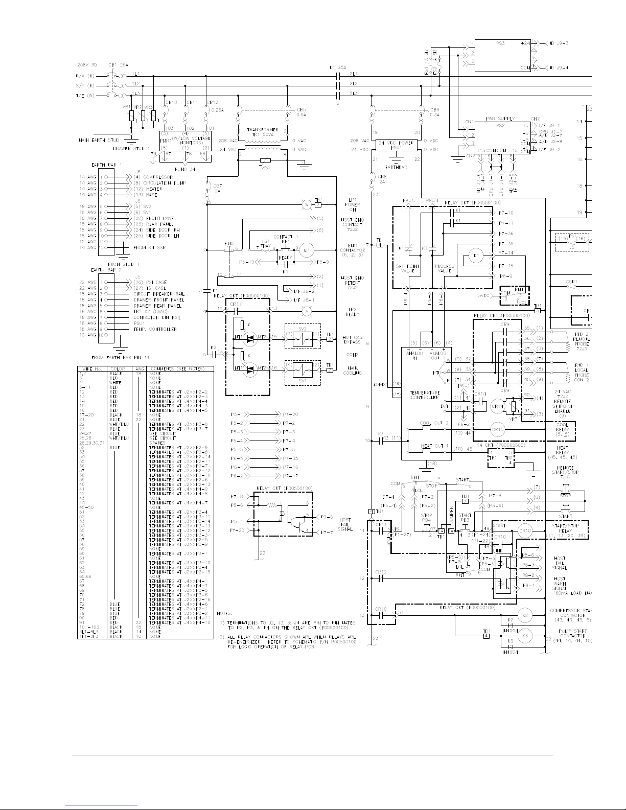
(G:\Technical Documents\MANUALS\W95900011- All)
88 TCU 40/80 plus Temperature Control Unit
Fig 29 - RS 232 Power Distribution Schematic

(continued …..) Fig 29 - RS 232 Power Distribution Schematic
(G:\Technical Documents\MANUALS\W95900011- All)
TCU 40/80 Temperature Control Unit 89
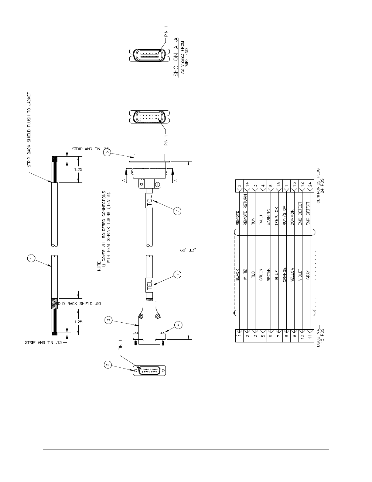
1
8
8
1
(G:\Technical Documents\MANUALS\W95900011- All)
90 TCU 40/80 plus Temperature Control Unit
1
1
Fig 30 - Assy,Cable,TCU Host Comm
 Loading...