

Page 1

1
Reference Guide
Product Code: TU120AE
PWR VC DC TR TD RD DS
Page 2

2
WEBGLIDER-460
Page 3

3
Before You Begin your Installation
The product you have purchased is designed to be easily installed with
most IBM PC or compatible systems in conjunction with an ISDN phone
line. The Quick Tour Installation Guide contains detailed instructions and
is where you should begin installation. Most included software has
automatic installation programs to place the software correctly onto your
computer. However, as all computers are configured differently, you may
be required to perform some basic DOS or Windows tasks. If you are not
familiar with basic DOS commands such as DIR, CD, or EDIT, you
should check your DOS manual, or seek assistance from your local
computer dealer to install the product
.
How to get Technical Assistance
The dealer that you purchased this product or your computer from is the
first place you should go for technical assistance. The dealer is usually
the most qualified source of help, and is most familiar with your system
and how this product should be installed. Many dealers have customer
service and technical support programs, with varying levels of support
offered, depending on your needs and computer knowledge. Please
contact the dealer first whenever a problem occurs.
If your Dealer Can’t Assist you
If you can’t get assistance from your dealer, the manufacturer provides
varying levels of technical assistance as summarized on the following
page. The Standard Free Technical Support number is for quick answers
to specific inquiries on product features and technical questions (call 407-
241-8088; M-F, 8 am to 6:30 pm EST). Direct access to technical support
representatives is provided on a limited basis. If you require immediate
attention or in-depth help with the installation of the product, please call
our 900-priority support number for service. This number gives you
immediate access to senior-level technicians. The number is 900-555-4900.
You will be charged $2.00 per minute. The charges will appear on your
next phone bill.
Page 4
4
Boca BBS
407-997-9159
(ISDN)
407-241-1601
(analog)
On-Line Support!
CompuServe: GO BOCA
Internet:
email: support@boca.org
on the World Wide Web:
http://www.boca.org
Automated
1
2
4
3
5
7
6
8
9
Fax Retrieval
System
407-995-9456
1
2
4
3
5
7
6
8
9
Technical
Priority Service
Support Fax
900-555-4900
407-997-2163
($2 per minute)
Standard Free
Technical Support
407-241-8088
Damaged or Missing Items
We use many world-class quality assurance programs to ensure the
product you purchased is of the highest caliber. Sometimes, however, a
component may be missing from the box, or is damaged or corrupt in
some way. If this happens, immediately return the entire package to your
place of purchase so you may exchange it for a new one. Your dealer
should be able to provide you with an exchange far more quickly than by
contacting us directly. If for some reason you are unable to return the
product directly to its place of purchase, refer to the “Servicing Your
Product” and “Warranty” sections in this manual for instructions
.
WEBGLIDER-460
Page 5

Using the Boca Research WEBGLIDER-460 Reference Guide
This manual provides reference information for the WEBGLIDER-460.
WEBGLIDER documentation assumes the user has basic computer skills
and is familiar with personal computers. For installation, use the Quick
Tour Installation Guide. Our customer support experience has shown
that many costly and time-consuming calls to our technical support staff
can be avoided with closer attention to the information provided in the
documentation. In addition to following the instructions provided in
the WEBGLIDER documentation, you will also need to consult the
documentation supplied with your communications software.
IMPORTANT NOTICE
5
FCC Requirements
The Federal Communications Commission (FCC) restricts the way you
can use modems. Read the FCC compliance statement found in
Appendix E of this manual.
Copyright
©1996 Boca Research, Inc. All rights reserved. No r epr oduction of this document in
any form is allowed without permission in writing from Boca Research, Inc. Boca
Research is not liable for any damage resulting fr om technical or editorial errors or
omissions contained in this document. The information in this manual is subject to
change without notice. Revisions to the product(s) in this manual may occur at any
time without notice.
Trademarks
All Boca Research products ar e trademarks of Boca Resear ch, Inc. All other
references to computer systems, softwar e, and peripherals use trademarks owned
by their respective manufacturers.
Publication Date: February, 1996
Printed in the U.S.A. TU120AE.PM5
Page 6

6
Contents
Section One: Introduction ...................................................... 7
1.1 This Reference Guide ............................................................ 9
1.2 Package Contents ................................................................... 10
1.3 Notation Conventions Used ............................................... 1 1
Section Two: WEBGLIDER Interfaces & Features ....... 1 3
2.1 WEBGLIDER Interfaces ...................................................... 1 3
2.2 WEBGLIDER Indicators ...................................................... 16
Section Three: Installation ...................................................17
Section Four: Command Line Configuration ................. 19
Appendix A: Troubleshooting ............................................ 27
Appendix B: Cable Connections ........................................ 3 1
Appendix C: Command/Protocol Overview ................... 33
Appendix D: Technical Specifications ............................ 3 9
Appendix E: Compliance Information ............................. 41
Appendix F: Warranty ........................................................... 45
Appendix G: Servicing Your Boca Product .....................47
Appendix H: AT Command Reference ............................ 5 1
Mode Selection ............................................................................................53
Extended Call Control ............................................................................... 55
DTE Interface...............................................................................................56
Miscellaneous.............................................................................................. 62
S-Registers .................................................................................................... 65
Response Codes........................................................................................... 70
Extended Response Codes ....................................................................... 71
Appendix I: Additional Command Line Options ......... 7 5
Appendix J: Microsoft’s Remote Access Server ............ 91
Appendix K: Dial-Up Networking for Windows 95 .... 9 3
Appendix L: Glossary ............................................................ 95
WEBGLIDER-460
Page 7

Introduction 1
The WEBGLIDER is a Basic Rate Integrated Services Digital
Network (ISDN) terminal adapter that allows connection of a PC
(or other data terminal equipment) and up to two telephone
devices (such as telephones, modems or faxes) to ISDN. This
product was designed specifically for North American ISDN.
The WEBGLIDER allows you to
connect your PC to the Internet,
telecommute to a central site,
7
INTRODUCTION
connect to other remote PCs, or
computer systems. At the same
PWR VC DC TR TD RD DS
The WEBGLIDER
The on-board high speed processor handles all ISDN processing,
channel aggregation and data compression giving the
WEBGLIDER very fast connect times and very high throughput
allowing connections to data terminal equipment at up to
460.8Kbps*.
The WEBGLIDER connects to the U-interface of the ISDN
time your existing telephone
equipment can be used to make
calls to other equipment on the
Public Switched Telephone
Network (PSTN).
allowing direct connection to the ISDN without the need for an
NT1 device. NOTE: Do not attach the WEBGLIDER to an NT1
device.
Introduction
Page 8

8
Basic Rate ISDN provides two 64 kbps B-channels, each of which
can carry a data or a ‘voice’ call. This allows the WEBGLIDER to
handle two simultaneous ‘voice’ calls (telephone, fax or modem),
or a ‘voice’ call and an ISDN data call, or a data call that uses both
B-channels (128 kbps).
Industry standard V.120 rate adaption and V.42bis data
compression ensure interoperability with ISDN equipment from
other vendors. The WEBGLIDER is able to store up to 32 different
numbers and has directories of stored numbers for positive
(“whitelisting”) and negative (“blacklisting”) checking of caller ID,
allowing secure applications to be developed.
The industry standard AT command set is also included.
Familiarize yourself with the following terms before continuing.
ANALOG PHONE DEVICE: Regular phone handset, fax
machine, etc.
AUX1/AUX2: POTS ports on the back of your WEBGLIDER.
BRI.: Basic Rate Interface
DN: Directory Numbers (phone numbers) given to you by your
phone company when you get ISDN service
NETWORK (ISDN): Type of switching equipment the phone
company uses to connect your ISDN line to their CO (central
office)
POTS port: (Plain Old Telephone Service), i.e., RJ-11 phone-type
jack into which you can plug standard devices like fax machines
or telephone handsets.
SPID: Service Profile ID (supplied by your phone company)
TA: Terminal Adapter (usually ISDN modem)
WEBGLIDER-460
Page 9

1.1 This Reference Guide
9
This manual provides a technical reference for the
WEBGLIDER.
Section 1... (this section) provides a description of
package contents and tells you where to
get started.
Section 2... describes the WEBGLIDER connectors
and indicators.
Section 3... describes the physical installation.
Section 4... shows you how to configure your
WEBGLIDER with command line options;
otherwise, refer to the Quick Tour Installation
Guide
.
Appendices... provide troubleshooting guidance,
extensive reference information (including
specifications, a comprehensive AT
command reference, and a glossary),
regulatory and warranty information,
and how to service your Boca product.
*(With two WEBGLIDERS, each using a Boca IO650 serial card, V.42bis
compression, and rate aggregation).
Introduction
Page 10

10
1.2 Package Contents
The WEBGLIDER package contents are illustrated below. The
package contains:
• WEBGLIDER
• power supply
• RJ-45 cable
• RS-232 serial cable
• this Reference Guide
Other software,
CDs,
documentation, and
special introductory
offers may also be
included.
• Quick Tour installation guide
• Ordering ISDN Services guide
• software diskette(s).
Examine the contents of your WEBGLIDER package and check for
damage. Contact your supplier or distributor if any of the items
listed above are missing or physically damaged. Do not install
damaged equipment.
WEBGLIDER-460
PWR VC DC TR TD RD DS
Page 11

1.3 Notation Conventions Used
The following notations are used to describe commands:
Description Meaning
<parameter description> mandatory parameter
[parameter description] optional parameter
| option separator
Text in the following font:
SET NETWORK NI2
11
indicates input to, or output from the
WEBGLIDER
.
Introduction
Page 12

12
WEBGLIDER-460
Page 13
13
WebGlider Connections & Features 2
This section is a quick tour of the WEBGLIDER.
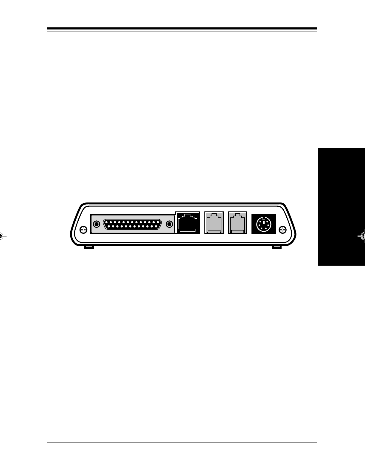
2.1 WEBGLIDER Interfaces
The WEBGLIDER is a Basic Rate Integrated Services Digital
Network (ISDN) terminal adapter that allows connection of a PC
(or other data terminal equipment) and up to two telephone
devices (such as telephones, modems or faxes) to ISDN. The
interface connectors are located on the back panel of the unit.
QUICK TOUR
WEBGLIDER
ISDN URS-232 AUX 1 AUX 2 PWR
WEBGLIDER Back Panel
ISDN Connection
The WEBGLIDER connects directly to the ISDN network at the Uinterface. An ISDN network terminator device (NT1) is not
required. This port is labelled ‘ISDN-U’ and we have supplied an
RJ-45 cable for connecting to the ISDN network. NOTE: Do not
attach the WEBGLIDER to an NT1 device.
Serial Connection
The WEBGLIDER has a serial port for connecting to your PC or
other Data Terminal Equipment (DTE). This port is labelled ‘RS232’ and is located on the back panel. The port appears as a DCE
(modem-like) connection and can be directly connected to
terminal equipment using standard cables.
Connection & Features
Page 14

14
Telephone Connections
Two “voice” or POTS (Plain Old Telephone Service) ports are
provided for connecting telephone equipment such as telephones,
answering machines, faxes, or modems to the WEBGLIDER.
These ports are labelled ‘AUX 1’ and ‘AUX 2’. Each port supports
multiple telephone-type devices up to a Ringer Equivalence
Number (REN) of three. WEBGLIDER allows both lines to be used
at the same time for two simultaneous telephone calls, if no data
call is present. If a data call is present, you can only use one AUX
line.
Power Connection
Power for the WEBGLIDER is provided by an external power
supply. The power supply is attached to the connector (marked
‘PWR’) on the back panel. The WEBGLIDER does not draw power
from the ISDN network. So, if there is no power to the
WEBGLIDER, then the telephone ports will not work.
Typical Configuration
The illustration on the next page shows a typical WEBGLIDER
configuration with a PC, a telephone, and a fax machine connected
to an ISDN line. For a typical configuration (if you have an analog
modem), you should assign one AUX port exclusively for that
modem. This will allow you to establish either an analog modem
call, or a voice call, using a handset plugged into the modem. You
can then tele-conference while working on the same document,
engage in two-player remote game playing, or do an analog data
download. If you do not have an analog modem, just assign one
AUX port exclusively to a handset.
WEBGLIDER-460
Page 15

ISDN
Network
15
You may also
have a standard
modem in your
PC connected to
a standard RJ-11
phone line
Fax
(optional)
(optional)
BRI
PWR VC DC TR TD RD DS
PCTelephone
Power
supply
TO
POWER
SUPPLY
TO SERIAL
PORT ON
TO ISDN
NETWORK
COMPUTER
ISDN URS-232 AUX 1 AUX 2 PWR
TO FAX
MACHINE
in this
example
(optional)
TO STANDARD
ANALOG
TELEPHONE in
this example
(optional)
Connection & Features
Page 16
16
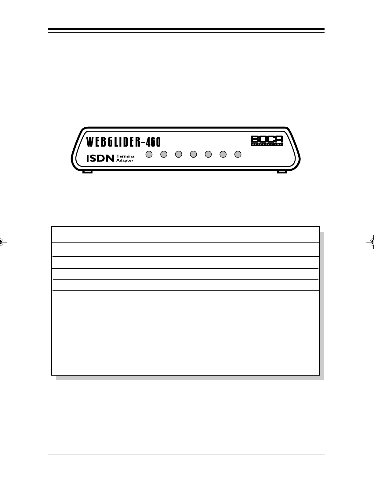
2.2
WEBGLIDER
Indicators
The WEBGLIDER’s status indicators are located on the front
panel.
PWR VC DC TR TD RD DS
The WEBGLIDER front panel.
There are six status indicators on the front panel:
Indicator Meaning
PWR Power: The WEBGLIDER is powered on.
VC Voice Call: A call is established on AUX 1 or AUX2.
DC Data Call: A data call is established for the RS-232 port.
TR Data T erminal Ready. The DTE has DTR asserted.
TD Transmit Data: Data is being sent by the DTE.
RD Receive Data: Data is being received by the DTE.
DS D-Channel Status: The indicator is OFF when the
WEBGLIDER is not connected to the ISDN network. The
indicator flashes when the ISDN network is detected and
connection to the central office is starting up. The indicator is
ON solid when the WEBGLIDER is ready for use (to make or
receive calls from either the RS-232 port, or one of the AUX ports.)
The WEBGLIDER status indicators
The status indicators are also used during the Power On Self Test
(POST).
WEBGLIDER-460
Page 17

Installation 3
1. Connect the output from the power supply lead to the socket
marked 'PWR' on the back panel of the WEBGLIDER.
Note: This should be done BEFORE plugging the power
adapter into the AC outlet.
Safety Statement
17
Use only the power supply shipped with the product.
2. Use a serial cable to connect the port marked ‘RS-232’ to your
PC or other device that will be used for configuration. The
WEBGLIDER is wired as a DCE allowing standard modem
cables to be used. Full information on the cable required is
provided in Appendix B: Cable Connections.
3. Connect the socket marked ‘ISDN U’ on the back panel to the
ISDN network using the cable supplied. The ISDN network
normally terminates with an eight-way RJ-45 socket.
Note: DO NOT CONNECT the WEBGLIDER to an NT1 or any
other device providing an S-interface to ISDN.
INSTALLATION
Installation
Page 18

18
Safety Statement
Do not install telephone wiring or connect/disconnect
ISDN equipment during an electrical storm.
4. You may now connect your telephone equipment to the AUX
port(s) or, you may choose to do this after the unit has been
configured. Use the cables provided with your telephone
equipment to connect to AUX 1 or AUX 2. If there is no power
to the WEBGLIDER, then the telephone ports will not work.
5. Connect the power supply to the AC outlet.
6. Verify that the PWR LED on the WEBGLIDER is ON.
WEBGLIDER-460
Page 19

Command Line Configuration 4
If you use an operating system other than Windows, command
line configuration should be used. This method uses a series of
simple SET and SHOW commands to set the WEBGLIDER
operating parameters. If you are configuring through Windows,
refer to the Quick Tour Installation Guide. For a comprehensive
description of all command-line options, see Appendix I in this
manual.
Before continuing with this section, you should familiarize
19
CONFIGURATION
COMMAND LINE
yourself with the following terms:
ANALOG PHONE DEVICE: Regular phone handset, fax
machine, etc.
AUX1/AUX2: POTS ports on the back of your WEBGLIDER.
BRI.: Basic Rate Interface
DN: Directory Numbers given to you by your phone company
when you get ISDN service
NETWORK (ISDN): Type of switching equipment the phone
company uses to connect your ISDN line to their CO (central
office)
POTS port: (Plain Old Telephone Service), i.e., RJ-11 phone-type
jack into which you can plug standard devices like fax machines
or telephone handsets.
SPID: Service Profile ID (supplied by your phone company)
TA: Terminal Adapter (usually ISDN modem)
Now, continue with the next page to prepare the WEBGLIDER for
command line configuration.
Command Line Configuration
Page 20

20
NOTE: When the WEBGLIDER is configured correctly, the DS
indicator will blink at first and then remain on solid. If it is not
configured correctly, the DS indicator will blink continuously.
1. Power on the WEBGLIDER and wait for the self-test sequence
to be performed. Start your modem software and go to the
command screen where you can issue modem “AT”
commands.
2. Configure your software for the COM port to which the
WEBGLIDER is attached. Set the COM port speed to the
desired value. Set the flow control to ‘hardware’ (usually RTS/
CTS). Keep compression (V.42bis) disabled for now. If your dialup service supports compression, re-enable it at a later time.
3. Type AT and press ENTER (or carriage return for non PCs). The
OK response should be seen. If you do not see the A character
after pressing A, press it a few more times until the
WEBGLIDER detects the baud rate and displays an A character.
4. Type ‘AT’ and press ENTER. When you have received the OK
response, enter the following command: AT&Q4 and press
ENTER.
The following prompt will appear: ISDN-TA>
The WEBGLIDER is now ready to be configured for use. In the
example that follows, the information below is used:
WEBGLIDER-460
Page 21

Network NI1
DN1 555-1111
SPID1 6175551 1110100
DN2 555-2222
SPID2 61755522220100
RS232# 5551111
AUX1# 5552222
AUX2# 5551111
5. The first item to configure is the network type. This will be
either National ISDN-1, National ISDN-2, AT&T 5ESS custom
21
or Northern Telecom DMS-100 custom. Depending on your
switch type, enter the command as follows:
For National ISDN-1 (default)
SET NETWORK NI1
or for National ISDN-2
SET NETWORK NI2
or for AT&T 5E5 custom
SET NETWORK AT5
or for AT&T 5E6, 5E7, 5E8, 5E9 custom
SET NETWORK AT9
or for Northern Telecom DMS-100 custom
SET NETWORK DMS
Note: Some AT&T 5ESS and DMS-100 switches run custom;
others run National ISDN (NI1 or NI2) protocols. Check this with
your ISDN provider.
Command Line Configuration
Page 22

22
6. Your ISDN provider will have provided you with Directory
Numbers (DNs). These are your ISDN numbers. Each DN is
provided with a Service Profile ID (SPID). The SPID is normally
based on the DN and includes the area code and a suffix. You
need to configure the WEBGLIDER with your DNs and SPIDs.
To do this, use the command:
SET DN 1 <dn 1> <spid 1>
Where dn 1 is one of your directory numbers (usually your main
number) and spid 1 is the associated SPID.
Note: The DN does not include the area code. Repeat this
command for your other directory numbers, using SET DN 2 for
the second number etc.
Example: (area code 617, SPID suffix 0100)
SET DN 1 5551111 61755511110100
SET DN 2 5552222 61755522220100
This example sets the first Directory Number to 5551111 with SPID
61755511110100 and the second Directory Number to 5552222 with
SPID 61755522220100.
7. Now that we have set the DNs and SPIDs, we can assign ISDN
numbers to the WEBGLIDER ports. Assigning numbers to ports
allows incoming calls to be sent to the right ports.
To set the ISDN number for the RS-232 (data) port use the
command: SET RS232 DN <dn>
WEBGLIDER-460
Page 23

To set the number for the AUX 1 port use the command:
SET AUX1 DN <dn>
and to set the number for AUX 2 use the command:
SET AUX2 DN <dn>
Where dn is the directory number you wish to use for this port.
23
Note:
The directory number used for an AUX port must have been
assigned previously using the SET DN command.
Example:
SET RS232 DN 5551111
SET AUX1 DN 5551111
SET AUX2 DN 5552222
This example sets the DN for the RS-232 port to 5551111, the DN
for AUX 1 to 5551111, and the DN for AUX 2 to 5552222.
Note: The RS-232 and AUX 1 ports have the same number.
Incoming calls will be routed to the correct port on call type
(voice calls to AUX 1 and data calls to RS-232). ISDN digital data
will be answered by the TA only (special signalling) and analog
calls for an analog modem, fax machine, or phone will pass
through to one of the AUX ports. Do not assign the handset to
the same AUX port assigned to the RS232. This is so that when
the RS232 port is busy with an ISDN signal, connection through
the phone is still available.
Command Line Configuration
Page 24

24
8. Before saving, you should make sure all settings are as you
intended. At the ISDN-TA prompt, type the following and press
ENTER:
SHOW NETWORK
(shows the network (switch type) the WEBGLIDER is configured for)
SHOW DN
(shows all DNs and SPIDs)
SHOW RS232 DN
(shows the DN assigned to the RS232 data port)
SHOW AUX1 DN
(shows the DN assigned to the AUX1 port)
SHOW AUX2 DN
(shows the DN assigned to the AUX2 port)
9. To save the configuration, enter the command:
SAVE
This operation will take a few seconds to complete.
To leave configuration mode without saving, type EXIT. You can
now use AT commands.
WEBGLIDER-460
Page 25

25
Summarizing the Commands from the Previous Example
Note: If your switch is running one of the 5E custom protocols, it
may be configured as point-to-point or multipoint (default).
Enter the following command only if you have an AT&T custom
point-to-point configuration:
ISDN-TA>SET TOPOLOGY POINT-TO-POINT
Example:
ISDN-TA>SET NETWORK NI1
(This sets the WEBGLIDER for National ISDN-1 switch type.)
ISDN-TA>SET DN 1 5551111 61755511110100
(where the DN1 is 5551111 and the SPID1 is 61755511110100)
ISDN-TA>SET DN 2 5552222 61755522220100
(where the DN2 is 5552222 and the SPID2 is 6175552220100)
ISDN-TA>SET RS232 DN 5551111
(where the phone number to the RS232 port to send/receive data
is set to 5551111)
ISDN-TA>SET AUX1 DN 5551111
(where the AUX1 POTS port is set to use 5551111)
ISDN-TA>SET AUX2 DN 5552222
(where the AUX2 POTS port is set to use 5552222)
ISDN-TA>SAVE
NOTE: When the WEBGLIDER is configured correctly, the DS
indicator will blink at first and then remain on solid. If it is not
configured correctly, the DS indicator will blink continuously.
Command Line Configuration
Page 26

26
You have now set up your WEBGLIDER for basic operation, you
should now be able to make and receive calls from all three ports.
To make a call on the data port, use AT dialing through your
communications software. To make a call on AUX1 or AUX2, pick
up the handset, wait for a dial tone, and make a call in the normal
way. Or, use AT dialing through the communications software you
have configured for your analog modem attached to one of the
AUX ports.
Configuration is not limited to the items discussed above. See
Appendix I for a full explanation of each command line option.
WEBGLIDER-460
Page 27

Troubleshooting A
Should your WEBGLIDER not function as expected, check the
following before seeking support:
WEBGLIDER will not respond to DTE
27
1. Check the LEDs to make sure that the power on self-test has
completed successfully. When the test completes successfully,
the LEDs will flash in a sweep sequence. If a test fails, one or all
of the LEDs will be flashing.
2. Make sure that the cables used conform to the specifications
defined in Appendix B of this manual and that both ends of the
cables are securely connected.
3. The WEBGLIDER will autobaud to the speed of your DTE. If
autobaud appears not to work after pressing the A key several
times, try changing the speed of your DTE. If you are using a
PC, make sure your communication software is also configured
to use the correct COM port.
TROUBLESHOOTING
4. Some asynchronous devices have specific requirements for DCD
and DSR operation. The default behavior of these signals for the
WEBGLIDER is that DCD and DSR are always on for AT
dialing. Check that this method of operation is acceptable to
your PC or terminal. DCD and DSR behavior can be modified
using the AT&C and AT&S commands.
Troubleshooting
Page 28

28
5. If you are using AT dialing and the WEBGLIDER was
previously responding, it could be that the AT interface has
been reconfigured not to respond. To check this, enter ATE1Q0
to enable ‘echo’ and disable ‘quiet mode’.
Get AT response but cannot make a
call on data port, or no dial tone on
AUX port
1. If the DS light is off, check the connection to the ISDN line and
make sure that the WEBGLIDER is not connected to an NT1.
Also check that the network type is configured correctly.
2. If the DS light is flashing, there may be a problem with your
SPIDs or the network type configuration. Check your SPIDs
with your ISDN service provider (telco) and try adding trailing
zeroes to the SPID. If you change the SPIDs don’t forget to
SAVE the configuration. Ask your service provider to run a test
on your line from the central office.
3. Try setting the CALL SETUP option to both MINIMUM and
MAXIMUM.
WEBGLIDER-460
Page 29

29
WEBGLIDER displays double characters
Local-echo is enabled in the terminal. Reconfigure the terminal to
disable the local echo.
WEBGLIDER connects but the connection is
then lost
1. If you are using rate adaption, check that the device you are
connecting to is configured for the same rate adaption standard
as the WEBGLIDER. The WEBGLIDER uses V.120, which will
not interoperate with V.110.
2. Check that the PPP is not enabled if calling a line without PPP.
Disable PPP by typing AT&Q0. Enable it by typing AT&Q3.
WEBGLIDER will not auto-answer on RS-232
port
In AT dialing mode ‘automatic-answer’ is enabled by setting the
value of the S0 register to 1 (ATS0=1).
WEBGLIDER very slow or re-booting
Serial cables greater than a few feet in length connected to the
WEBGLIDER and left unterminated may cause problems. These
cables should be plugged into a DTE or disconnected from the
WEBGLIDER.
Troubleshooting
Page 30

30
WEBGLIDER-460
Page 31

31
Cable Connections B
We recommend the example cables illustrated in this appendix for
use with your WEBGLIDER.
B1 WEBGLIDER to 25-way DTE
Use this cable to connect the RS-232 port of the WEBGLIDER to a
DTE with a 25-pin D-type connector.
11
2
3
4
WEBGLIDER
'RS-232'
(DB25)
5
6
7
8
15
17
20
22
20
22
1
2
3
4
5
6
7
8
1 Frame GND
2
2 Tx
3
3 Rx
4
4 RTS
5
5 CTS
6
7
6 DSR
8
7 GND
15
DTE
(DB25)
8 DCE
17
20 DTR
20
22 RI
22
CABLE CONNECTIONS
WEBGLIDER to 25-way DTE
Cable Connections
Page 32

32
B2 WEBGLIDER to IBM Compatible
PC
Use this cable to connect the RS-232 port of the WEBGLIDER to
the 9-way serial port of an IBM compatible PC.
1
1
2
2
1
1 DCD
3
4
WEBGLIDER
'RS-232'
(DB25)
5
6
7
8
20
22
WEBGLIDER to IBM Compatible PC
3
4
5
6
7
8
20
22
2
2 Rx
3
3 Tx
4
4 DTR
5
5 GND
6
7
6 DSR
8
7 RTS
9
8 CTS
9 RI
PC
Serial
Port
(DB9)
WEBGLIDER-460
Page 33

33
Command/Protocol Overview C
In most cases, your communications software will set and
control the operation of your WEBGLIDER. Following is a brief
survey of the most commonly used Hayes-compatible AT
commands for use with your WEBGLIDER. In addition, we’ve
also provided information on extended AT command sets, SRegisters, and commands and registers for high-level protocols
such as MNP, V.42/V.42bis, and V.32/V.32bis.
NOTE: This section makes references to Hayes-compatible
commands, originally developed for analog modem
OVERVIEW
COMMAND/PROTOCOL
communications. Bear in mind the WEBGLIDER is not an
analog modem. It is a digital device allowing communication
between two DTE devices, and is also referred to as terminal
adapter (TA). The WEBGLIDER supports the AT command set
to ensure compatibility with today’s communication programs.
It will rarely be necessary to use ‘AT’ commands and SRegisters in command or terminal mode. We include them here
for more advanced users who may prefer command mode
operation, or r equire special settings. See pages 51-74 for
additional details.
Hayes-compatible commands consist of a basic command set
and an extended command set. The basic set involves functions
such as dialing a number, or putting the modem on-hook (i.e.,
replacing the telephone handset).
Extended commands allow more sophisticated control of the
device such as adjusting transmission speed, or initiating highlevel functions like data compression or error correction. These
functions are defined and controlled by the available protocols
mentioned above. A protocol is a set of standards by which
Command/Protocol Reference
Page 34

34
data communications operate. Every AT command includes an
“AT” prefix, followed immediately by the command and, in
many cases, additional parameters. Multiple commands can be
entered at the same time from your communications software.
AT Command[parameter] [parameter] ...
PRESS ENTER
Example: ATH or ATH0 tells the modem to disconnect
Extended commands were developed to provide greater
functionality and control over modem operations. Their format is
the same as the basic command except that an additional
parameter is required following the AT prefix and before the
numerical parameter. Examples: AT&V displays the value of the
S-Registers, configuration parameters, and ISDN address
directory (the stored numbers).
S-Registers
Modem command “language” also employs a set of indicators or
registers, which are various numerical values all with a standard
“S” prefix, hence S-Registers. To a large extent, the values defined
in the S-Registers regulate the operation of the WEBGLIDER and
the function of some commands in the AT command set.
Example: S-Register 7, or S7=n, defines the length of time the
WEBGLIDER will wait for an outgoing call to be established
before reporting NO CARRIER to the DTE. In this case, the
acceptable range is 0-255 with a default value of 20. With S7=20,
the WEBGLIDER will wait 20 seconds for an outgoing call to be
established before reporting NO CARRIER.
WEBGLIDER-460
Page 35

35
Data Communication Protocols
These protocols represent various domestic and international
standards which enhance modem performance and reliability. The
protocols are activated and controlled by a variety of extended AT
commands and S-Registers.
MNP stands for Microcom Networking Protocol and is a protocol
developed by Microcom for full-duplex, error-free
communications. This protocol detects and corrects errors which
can result from telephone line noise and other signal distortions.
There are several classes of MNP operation also referred to as
service classes. Class 5 maximizes data transfer rate and provides
compression which can significantly increase data throughput.
The “V-Dot” standards are more numerous, but have a single
origin: the International Telecommunications Union
Telecommunications Standards Sector (formerly the Consulting
Committee for International and Telephone and Telegraph or
CCITT). Some of the lower-level standards such as V.21 and V.22
have “domestic” equivalents as developed by the former Bell
System, also referred to as Bell standards. The “V.Dot” standards
may be summarized as shown on the following page.
Command/Protocol Reference
Page 36

36
V.21 The CCITT standard for 300bps communications.
Domestic modems follow the Bell 103 standard,
but V.21 can accept international calls at 300bps.
V.22 The CCITT standard for 1200bps communications.
The domestic equivalent is the Bell 212A standard.
V.22bis The CCITT standard for 2400bps.
V.23 CCITT for 1200bps with a 75bps back channel. This is
mostly used in Europe and South America.
V.24 CCITT serial interface standard (EIA/RS232-D).
V.25bis Automatic calling and answering protocol, originally
intended for use over PSTN.
V.32 CCITT standard for 9600bps and 4800bps
communications.
V.32bis CCITT standard for an extensive range of high-speed
modems operating at 14,400bps, 12Kbps, 9600bps,
7200bps, and 4800bps.
V.34 ITU-TSS protocol. It can operate up to 28,800bps for
data and 14,400bps for send/receive fax.
V.42 CCITT standard for detection and negotiation for
LAPM (Link Access Procedure for Modems) error
control. V.42 will also support MNP levels 2-4.
WEBGLIDER-460
Page 37

V.42bis An extension of V.42 specifying the data compression
protocol for use with V.42.
V.110 Rate Adaption standard for ISDN B-channel
V.120 Rate adaption and multiplexing standard for ISDN B-
channel
37
Command/Protocol Reference
Page 38

38
WEBGLIDER-460
Page 39

Technical Specifications D
Power requirements
North America: 120V AC @60Hz
Unit power consumption
39
Normal operation: 2.5 W Maximum
Ringing: 3.5 W Maximum
Dimensions
Length: 7 9/16 ” (192 mm)
Width: 5 9/16 ” (141 mm)
Height: 1 5/32” (30 mm)
Mass
1.10 lb (0.50 kg)
SPECIFICATIONS
Environment
Operational: Temp: +5°C to +50°C
Humidity: 10 % to 90 % non condensing
Non-Operational: Temp: -30°C to +80°C
Humidity: 5% to 95% non condensing
Technical Specifications
Page 40

40
Interfaces
RS-232 Port: Connector - DB-25 female
Operation - RS-232 asynchronous
ISDN Port: Connector - RJ-45 (ISO 8877)
Layer 1 - ANSI T1.601 (ISDN U-interface,
2B1Q) with metallic termination
AUX 1: Connector - RJ-11 4 way
Operation - Telephone interface (network
presentation), DTMF dialing, REN 2
AUX 2: Connector - RJ-11 4 way (wired with
AUX 1 and AUX 2)
Operation - Telephone interface (network
presentation), DTMF dialing, REN 2
Central office support
National ISDN-1
National ISDN-2
AT&T 5ESS 5E5, 5E6, 5E7, 5E8, 5E9 custom and
National ISDN
Northern Telecom DMS-100 BCS 32 and above,
NIS 208.5 & 6.
EKTS support
Yes
Supplementary services
Calling Line ID Presentation (CLIP), also known as Caller ID
User-to-User Information (UUI)
WEBGLIDER-460
Page 41

41
Compliance Information E
FCC Statement:
“This device complies with part 15 of the FCC rules. Operation is subject
to the following two conditions:
(1) This device may not cause harmful interference.
(2) This device must accept any interference received including
interference that may cause undesired operation.
THIS UNIT COMPLIES WITH FCC PART 68 AS OF DATE OF
MANUFACTURE.
This equipment has been tested and found to comply with the limits for
a Class B digital device, pursuant to Part 15 of FCC rules. These limits
are designed to provide reasonable protection against harmful
interference in a residential installation. This equipment generates, uses,
and can radiate radio frequency energy and, if not installed in accordance
with the instructions, may cause harmful interference to radio
communications. However, there is no guarantee that interference will
not occur in a particular installation. If this equipment does cause
harmful interference to radio or television reception, which can be
determined by turning the equipment off and on, the user is encouraged
to try to correct the interference by one or more of the following
measures:
• Re-orient or relocate the receiving antennae.
• Increase the separation between the equipment and the receiver.
• Connect the equipment into an outlet on a circuit different from that to
which the receiver is connected.
• Consult the dealer or an experienced radio/TV technician for help.
Note: This unit was tested with shielded cables on the peripheral devices.
Shielded cables must be used with the unit to insure compliance.
INFORMATION
COMPLIANCE
Note: The manufacturer is not responsible for any radio or TV
interference caused by unauthorized modifications to this equipment.
Such modifications could void the user’s authority to operate the
equipment.”
Page 42

42
Notification to the Telephone Company
Notification to the telephone company is no longer required prior to
connecting the registered equipment but upon request from the telephone
company the user shall tell the telephone company which line the
equipment is connected to as well as the registration number and the
ringer equivalence of the registered protective circuitry. In most, but not
all areas, the sum of all RENs should be 5.0 or less. The FCC Registration
number and Ringer Equivalence number are printed on the main chip in
the center of the internal modem board, or on the underside of the
external modem.
Malfunction of the Equipment
In the event that the device should fail to operate properly, the customer
shall disconnect the equipment from the telephone line to determine if it
is the customer ’s equipment which is not working properly, or if the
problem is with the device, the user shall discontinue use until it is
repaired. In the event service is needed the user should contact the
vendor from whom you purchased the device.
Telephone Connection Requirements
Except for telephone company-provided ringers, all connections to the
telephone network shall be made through standard plugs and standard
telephone company-provided jacks, or equivalent, in such a manner as to
allow for easy and immediate disconnection of the terminal equipment.
Standard jacks shall also be arranged that, if the plug connected thereto is
withdrawn, no interference to the operation of the equipment at the
customer ’s premises which remains connected to the telephone network,
shall occur by reason of such withdrawal.
Incidence of Harm
Should terminal equipment or protective circuitry cause harm to the
telephone network, the telephone company shall, where practical, notify
the customer that temporary discontinuance of service may be required;
however, where prior notices are not practical, the telephone company
may temporarily discontinue service if such action is deemed reasonable
in the circumstances. In the case of such temporary discontinuance, the
telephone company shall promptly notify customers and will be given
the right to bring a complaint to the FCC if they feel the disconnection is
not warranted.
WEBGLIDER-460
Page 43

43
Changes in Telephone Company Equipment or
Facilities
The telephone company may make changes in its communications
facilities, equipment, operations, or procedures, where such action is
reasonably required and proper in its business. Should any such changes
render the customer ’s terminal equipment incompatible with the
telephone company facilities, the customer shall be given adequate notice
to make modifications to maintain uninterrupted service.
General
The FCC prohibits customer-provided terminal equipment be connected
to party lines or to be used in conjunction with coin telephone service.
Installation
The device is equipped with a USOC RJ-11 standard miniature modular
jack and is designed to plug directly into a modular jack.
Compliance Information
Page 44

44
DOC Compliance Statement (Canada)
The Canadian Department of Communications label identifies certified
equipment. This certification means that the equipment meets certain
telecommunications network protective operational and safety
requirements. The Department does not guarantee the equipment will
operate to the user ’s satisfaction.
Before installing this equipment, users should ensure that it is
permissible to be connected to the facilities of the local
telecommunications company. The equipment must also be installed
using an acceptable method of connection. In some cases, the company’s
inside wiring associated with a single line individual service may be
extended by means of a certified connector assembly (telephone
extension cord). The customer should be aware that compliance with the
above conditions may not prevent degradation of service in some
situations.
Repairs to certified equipment should be made by an authorized
Canadian maintenance facility designated by the supplier. Any repairs or
alterations made by the user to this equipment, or equipment
malfunction, may give the telecommunications company cause to
request the user to disconnect the equipment.
Users should ensure, for their own protection, that the electrical ground
connections of the power utility, telephone lines, and internal metallic
water pipe system, if present, are connected together. This precaution
may be particularly important in rural areas.
CAUTION Users should not attempt to make such connections
themselves, but should contact the appropriate electric inspection
authority or electrician, as appropriate.
The Load Number (LN) assigned to each terminal device denotes the
percentage of the total load to be connected to a telephone loop which is
used by the device to prevent overloading. The termination on a loop
may consist of any combination of devices subject only to the
requirement that the total of the load numbers of all the devices does not
exceed 100. The Load number appears on the underside of the
WEBGLIDER.
WEBGLIDER-460
Page 45

45
Warranty F
Limited Warranty
Boca Research, Inc. (BRI) warrants to the original buyer of this BRI product that the
hardware is free of defects in materials and workmanship for a period of five (5) years
from the date of purchase from BRI or its authorized dealer. Should the product fail to be in
good working order at any time during the five-year period, BRI, will at its option, repair
or replace this product as described below. This warranty does not cover defects resulting
from misuse, abuse, negligence, accident, repairs, or alterations made by either the
customer or another party. Boca Research reserves full rights to determine whether a
defective product falls into this category.
The entire risk as to the quality and performance of the product rests with the customer.
Any written or oral information or advice given by Boca Research dealers, distributors,
agents, or employees will in no way increase the scope of this warranty. This warranty
applies only to the product described in this manual and not to any other value-added
software which may be included.
All products will be serviced and returned via UPS-ground at no charge to customers.
All customers are required to demonstrate proof of purchase when requesting a Return
Merchandise Authorization (RMA). The period of service commences on the date of
purchase. A copy of the sales slip must be included with the returned merchandise.
WARRANTY
Products which require Limited Warranty service during the warranty period should be
delivered to BRI at the address in the Appendix (Servicing Your Boca Product) with proof
of purchase and the Return Merchandise Authorization (RMA) number provided by BRI
Technical Support. Refer to the Appendix in your manual. Replacement parts or complete
products will be furnished on an exchange basis only. Replaced parts and/or products
become the property of BRI.
If the returned product is sent by mail, the purchaser agrees to prepay shipping charges,
insure the product or assume the risk of loss or damage which may occur in transit, and to
use a shipping container equivalent to the original packaging. ALL EXPRESS AND
IMPLIED WARRANTIES OF MERCHANTABILITY AND FITNESS OF PURPOSE FOR
THE PRODUCT ARE LIMITED IN DURATION TO THE ABOVE FIVE- AND ONE-YEAR
PERIODS, RESPECTIVELY.
UNDER NO CIRCUMSTANCES (WHETHER BASED IN CONTRACT OR TORT) SHALL
BOCA RESEARCH BE LIABLE FOR INCIDENTAL, CONSEQUENTIAL, INDIRECT,
SPECIAL, OR PUNITIVE DAMAGES OF ANY KIND, OR FOR LOSS OF REVENUE, LOSS
OF BUSINESS, OR OTHER FINANCIAL LOSS AS A RESULT OF THE SALE,
INSTALLATION, MAINTENANCE, USE, PERFORMANCE, FAILURE, OR DISRUPTION
OF ITS PRODUCTS.
Boca Research reserves the right to make periodic changes or enhancements to any Boca
Research product without prior notification, but has no obligation to modify or update
products once sold.
This warranty gives you specific legal rights, and you have other rights which may vary
from state to state. This warranty is valid only in the United States.
Page 46

46
WEBGLIDER-460
Page 47

47
Servicing Your Boca Product G
If your WEBGLIDER-460 requires service, first contact the
authorized dealer from whom you purchased the product. If the
dealer is unable to assist you, and you must contact Boca
Research, Inc., please follow the instructions below.
Our ISDN BBS is available 24 hours a day at (407) 997-9159. You
may also contact our analog BBS at (407) 241-1601. Product
information is provided here along with special software and
utilities that may be downloaded.
BOCA PRODUCT
SERVICING YOUR
If the Troubleshooting section (Appendix A) did not resolve your
problem, you may call our technical support staff for assistance. If
you haven’t referred to the Troubleshooting section, do so now.
NOTE: CALLING TECHNICAL SUPPORT WITHOUT
COMPLETE AND ACCURATE INFORMATION
CONCERNING YOUR PROBLEM MAY BE BOTH TIMECONSUMING AND FRUSTRATING FOR YOU.
1. When calling Boca Research Technical Support, have the
following information available:
n Board or external unit name and part number
n Computer manufacturer
n Computer Model
n Peripherals in system
n Operating system and version
Servicing Your Boca Product
Page 48

48
If you suspect a problem with a specific program or software
package, make note of the name, version or release number,
and manufacturer of the software.
2. Call our Technical Support Department between the hours of
8:00 a.m. and 6:30 p.m. EST Monday through Friday at (407)
241-8088. A technician will be available to discuss the
problem(s) you are experiencing.
If factory service is required, you will be given a Return
Merchandise Authorization (RMA) number. Please place
this number on the outside of the package when you return
the item(s) for service and reference it on any
correspondence included in the package. Boca Research,
Inc. will return any product which is not accompanied by
an RMA number.
3. Refer to the Warranty Statement if the product is covered under
the five-year Boca Research, Inc. Limited Warranty.
4. Certain parts will not be covered under the Boca Research, Inc.
Limited Warranty. Dealer installed parts are warranted by the
dealer. Parts which you have installed yourself are covered only
by the supplier’s warranties. In these cases, Boca Research, Inc.
can identify which parts are defective, but will not replace such
parts until specific written authorization is received from you.
The cost of parts and labor involved in making such repairs will
be billed to you C.O.D.
5. When sending the WEBGLIDER-460 to Boca Research, Inc. for
repairs, please be sure to include:
WEBGLIDER-460
Page 49

49
n the WEBGLIDER-460 unit (external case only)
n a copy of the original invoice
n your return street address (for UPS purposes)
n phone number
n the RMA number mentioned above
Package the product securely in a container equivalent to the
original packaging, and insure the package to protect against loss
or damage during transit. Shipping charges must be prepaid;
C.O.D. shipments will not be accepted. Please use the address
below for all correspondence:
Boca Research, Inc.
RMA Department - RMA # _____________
1601 Clint Moore Road
Boca Raton, FL 33487-2841
6. If the repairs performed on your WEBGLIDER were covered by
the warranty, Boca Research, Inc. will return it prepaid via UPS.
Servicing Your Boca Product
Page 50

50
WEBGLIDER-460
Page 51

51
AT Command Reference H
Overview
Your WEBGLIDER provides serial, asynchronous dialing for the
data port (RS-232) using standard AT commands with extensions
for getting the most out of ISDN.
The ISDN command set was originally developed for use with Vseries modems that operate over the telephone network. While
keeping the standard AT commands that are used for making and
answering calls we have made enhancements to allow access to
ISDN supplementary services including caller ID and user-to-user
signalling over the D-channel at call setup and clear down time.
Note: Not all ISDN networks provide caller ID and user-to-user
signalling.
Introduction to Commands
AT commands are entered on a command line which starts with
the characters AT or at and ends when a Carriage Return (see S3
register) character is received. The maximum length of a
command line is 256 characters. Multiple commands can be
concatenated together, in which case the AT prefix need only
appear before the first command.
Example: ATS112=3VD14085552609
This single command has the same effect as the three commands:
REFERENCE
AT COMMAND
ATS112=3
ATV
ATD14085552609
AT Command Reference
Page 52

52
The command line may be edited using the Backspace (see S5
register) character. To repeat the last command A/ or a/ should
be entered (without Carriage Return). All commands are in
ASCII.
Introduction to Responses
The WEBGLIDER sends response codes to the PC (or DTE) when
commands are issued or events such as call establishment happen.
These response codes can be in English text (default) or numeric
code form. Numeric mode is useful when the device is being
software controlled. The commands Q and V can be used to set
the response mode. In text mode the WEBGLIDER will respond
to badly formed commands with ERROR. In most cases (but not
when dialing or answering) correctly formatted commands
receive an OK response when they have been processed.
All responses are in ASCII.
States
A port configured for AT dialing can be in one of two states,
command state or data state. When in command state the
WEBGLIDER interprets local DTE data as commands. The data
state is entered when a call is set up. In this state data from the
local DTE is sent over the connection to the remote DTE. The DTE
can get from data mode back to command mode using the escape
command (+++) and go back on-line again when required using
the online command (ATO).
WEBGLIDER-460
Page 53

Commands
This section describes the AT commands in detail, giving
examples where relevant. The commands are grouped
as follows:
• Mode selection
• Call control commands
• Extended call control commands
• DTE interface commands
• Miscellaneous commands
• Configuration
53
For notation conventions please refer to Section One.
Mode Selection
&Q Communication Mode
Syntax: AT&Q[0|1|2|3|4]
Description: Sets the communication mode as follows:
&Q0 AT dialing, asynchronous operation (default)
&Q1 DTR dialing, asynchronous operation
&Q2 Dial-on-data, asynchronous operation
&Q3 PPP mode (asynchronous to synchronous PPP
conversion; used for most Internet ISDN services)
&Q4 Command line configuration mode.
DTR dialing and dial-on-data are described in Section
Four. PPP mode provides AT dialing, but when the
connection is established asynchronous to synchronous
PPP conversion is enabled. Use this option if your
internet provider requires synchronous PPP. Command
line configuration is defined in Section Four.
AT Command Reference
Page 54

54
Call Control Commands
A Answer
Syntax: ATA
Description: This command causes an incoming call to be
answered. The command can be aborted by the PC (or DTE)
sending any character when the command is executing.
See also: *A, S0, RING
D Dial
Syntax ATD<isdn number[*subaddress]>
DescriptionInitiates a call to the ISDN address defined by isdn
number (and optional subaddress).
To dial a pre-stored number the following syntax should be used:
ATDS=n
where n is the index of the stored number.
Aggregated calls are made using the same command, two Bchannels are used rather than one, see &B.
Examples: ATD12025556000
An ISDN call is initiated to 12025556000.
ATD5550620*2 calls the equipment at 5550620, specifying
subaddress 2.
See also: *D, &Z, &B
H Hook
Syntax: ATH[0|1]
Description: This command causes a call to be cleared. This
command cannot be entered during a call while in data mode, the
user must escape back to command mode using ‘+++’.
H Same as H0
WEBGLIDER-460
Page 55

H0 Hang-up, clear call
H1 Go off-hook (do nothing, respond OK)
See also: +++, O
O Online
Syntax: ATO
Description: If a connection is established this command
causes an exit from the command mode into an on-line state.
See also: +++, H
Extended Call Control Commands
The following commands are ‘extended’ call commands
55
for ISDN; they allow access to the supplementary services
of ISDN. Note: Caller ID and user-to-user information (uui) are
not available on all networks, check with your ISDN provider.
*A Answer with optional UUI
Syntax: AT*A[,uui]
Description: Causes the incoming call to be answered. The uui
parameter allows optional user-to-user (D-channel) information to
be passed at this time. This information must be in double quotes.
The maximum length of uui depends on your network.
Example: AT*A,”Transaction Accept”
This example answers the call and sends the user-to-user
information Transaction Accept to the remote device via the ISDN
D-channel.
If the remote calling device is another Boca Research ISDN
product using AT dialing, this information will be received with
the CONNECTED response.
See also: *D, A, Extended Response Codes
AT Command Reference
Page 56

56
*D Dial with optional UUI
Syntax: AT*D/<isdn number[*subaddress]>/[uui]
Description: Initiates an ISDN call to the address specified by
isdn number and optional subaddress. The uui parameter allows the
inclusion of an optional connect time user-to-user (D-channel)
message. This information must be between double quotes.
Example: AT*D/5552234/”Transaction Request 53663:50”
In this example the ISDN number 5552234 is called with user-touser information Transaction Request 53663:50.
See also: D, *A, Extended Response Codes
*H Hang-up call with optional UUI
Syntax: AT*H[,uui]
Description: Causes the currently established call to be cleared.
User-to-user information can be passed at this time if the optional
uui parameter is included.
Example: AT*H,”Timeout”
The ISDN connection is closed and user-to-user information
Timeout is sent. A remote Boca Research ISDN product will
inform the user of the disconnection as follows:
CLEARED:16,”Timeout”
See also: H, Extended Response Codes
DTE Interface Commands
These commands configure the behavior of the RS-232 port. See
also S-registers S2, S3, S4, S5, S39, S95, S112.
E Echo
Syntax: ATE[0|1]
Description: This command controls whether command input
characters are echoed back to the DTE.
E Same as E0
E0 Echo disabled
E1 Echo enabled (default).
WEBGLIDER-460
Page 57

Q Quiet
Syntax: ATQ[0|1]
Description: This command controls whether or not result
codes should be sent back to the DTE on completion of
commands. The command is used as follows:
Q Same as Q0
Q0 Quiet mode disabled, results sent (default)
Q1 Quiet mode enabled, no results sent
See also: V
V Verbose
Syntax: ATV[0|1]
57
Description: This command controls the output format of
result codes, the two possible formats are verbose and numeric
(short form). Note: When quiet mode is enabled no response
codes will be sent to the DTE.
V Same as V0
V0 Numeric form
V1 Verbose literal form (default).
See also: Q
W Negotiation progress messages
Syntax: ATW[0|1|2]
Description: This command selects the format of the
connection negotiation progress messages.
W Same as W0
W0 The CONNECT message reports the port speed.
If S95 is 0 the extended negotiation messages are disabled
(default).
AT Command Reference
Page 58

58
W1 The CONNECT message reports the port speed.
If S95 is 0 CARRIER and PROTOCOL
messages are enabled. The CARRIER speed is the
ISDN B-channel speed.
W2 The CONNECT message reports the link speed.
If S95 is 0 the extended negotiation messages are disabled.
See also: S95
X Result code and call progress messages
Syntax: ATX[0|1|2|3|4]
Description: Configuration of response codes sent to DTE to
report call progress.
X Same as X4
X0,X1 Sends NO CARRIER when destination is busy.
Sends NO CARRIER when no B-channel is available or
no link to central office (C.O.) (default).
X2 Sends NO CARRIER when destination is busy
Sends NO Dial tone when no B-channel or no link to
C.O.
X3 Sends BUSY when destination is busy
Sends NO CARRIER when no B-channel or no link to
C.O.
X4 Sends BUSY when destination is busy
Sends NO Dial tone when no B-channel or no link to
C.O.
&B B-channel Profile selection
Syntax: AT&B[1|2|3|4]
Description: This command selects the current B-channel
profile. The B-channel profile controls data compression and rate
aggregation. Data compression uses the V.42bis standard and
WEBGLIDER-460
Page 59

59
allows data to be transferred between the two DTE devices (e.g.
PCs) above the speed of the ISDN link. Rate aggregation controls
whether the WEBGLIDER bonds the two 64 kbps B-channels
together to provide an ISDN link speed of 128 kbps.
Profile Data Rate
Compression Aggregation
&B1 1 (default) OFF OFF
&B 2 2 ON OFF
&B 3 3 OFF ON
&B4 4 ON ON
Incoming calls are handled in one of two modes. In the simplest
mode incoming calls need to match the current profile (i.e. the
remote terminal adapter must have the same data compression
and rate aggregation settings).
Automatic profile selection can be achieved where Multiple
Subscriber Numbering or subaddressing are available. Each of the
four profiles can be assigned a unique ISDN address, this allows
automatic profile selection for incoming calls depending on the
address called.
Port speed (the speed of transmission between the WEBGLIDER
and the DTE) can be any speed regardless of the settings of rate
aggregation and data compression. The WEBGLIDER will ‘flow
control’ the DTE if data cannot be sent over the ISDN fast enough.
Example: AT&B4S114=460
Enables rate aggregation and data compression and sets the port
speed to 460800 bps.
AT Command Reference
Page 60

60
&C Data Carrier Detect (V.24 circuit 109) behavior
Syntax: AT&C[0|1]
Description: This command selects the behavior of DCD,
as follows:
&C Same as &C0
&C0 DCD always asserted (default).
&C1 DCD asserted only when ISDN connection
established.
&D Data Terminal Ready (V.24 circuit 108) response
Syntax: AT&D[0|1|2|3]
Description: This command selects the response to changes in
the DTR signal, as follows:
&D Same as &D0
&D0 Ignore DTR
&D1 DTR drop puts WEBGLIDER in command state, but
does not clear call
&D2 DTR drop clears call (default)
&D3 DTR drop resets unit
&K DTE-DCE flow control
Syntax: AT&K[0|1|2|3|4]
Description: This command selects the flow control mechanism to
be used between the DTE and WEBGLIDER, as follows:
&K Same as &K0
&K0 No flow control
&K1 RTS-CTS flow control (default)
&K2 XON-XOFF flow control
&K3 As &K1
&K4 As &K2
Note: This command has the same effect as S39
WEBGLIDER-460
Page 61

&S Data Set Ready (V.24 circuit 107) behavior
Syntax: AT&S[0|1]
Description: This command selects the behavior of DSR,
as follows:
&S Same as &S0
&S0This command causes DSR to be always on (default)
&S1 This command causes DSR to be on when an ISDN
connection is established.
61
AT Command Reference
Page 62

62
Miscellaneous Commands
These commands allow setting and inspection of S-registers and
stored ISDN addresses, performing of internal tests, escaping back
from online mode to command mode and other general functions.
S S-register programming command
Syntax: ATSr=n
Description: This command is used to change the value of an
S-register. r is the number of the register and n is the new value.
I Internal tests
Syntax: ATI [0|1|2|3|4]
Description: This command provides identification information
and initiates internal tests as follows:
I Same as I0
I0 Display product identification
I1 Display ROM checksum
I2 Perform ROM checksum, returning OK or ERROR
I3 Display part number and revision level
I4 Display encoded product information
+++ Escape
Syntax: +++
Description: This escape sequence is used to exit from an
established connection back to command mode. To help prevent
the escape code being triggered by legitimate data, the escape
sequence should be preceded and followed by a one second
pause.
See also: O, S2
WEBGLIDER-460
Page 63

63
&O Display configuration
Syntax: AT&O
Description: Same effect as &V
&V Display configuration
Syntax: AT&V
Description: This command causes the values of the S-registers,
configuration parameters and ISDN address directory (the stored
numbers) to be displayed.
&W Save registers and options as user defaults
Syntax: AT&W
Description: The current settings for S-registers and all other
parameters (e.g., directory entries, DTR response, indication
format, security, call log etc.) are saved to non-volatile memory as
user defaults.
&Z Set directory entry
Syntax: AT&Z<dir id>=<dial string>
Description: This command stores the ISDN address dial string in
one of the 32 locations of the stored number directory. The location
is specified by <dir id>.
Example: AT&Z2=5556874
Sets stored number directory entry 2 to 5556874
Z Reset
Syntax: ATZ
Description: This command resets the WEBGLIDER and restores
registers from user defaults.
AT Command Reference
Page 64

64
Clear Flash memory (Control R)
To perform this procedure, do the following:
1. Turn the WEBGLIDER off.
2. Hold down the CTRL and R keys at the same time.
3. While holding the keys down, turn the WEBGLIDER back on.
4. Continue holding the keys until the indicators on the
WEBGLIDER stop flashing.
5. When the DC and TD indicator lights stay on solid, release the
CTRL and R keys. The WEBGLIDER will reboot again. Reset is
complete.
CAUTION: Use the CTRL/R function only when you wish to
clear the entire contents of flash memory and restore factory
default settings. NOTE: You will have to reconfigure the
WEBGLIDER after performing this procedure. Refer to the
Quick Tour Installation Guide (“Running the Configuration
Utility”). Also, the WEBGLIDER loses date and time following
a reset.
WEBGLIDER-460
Page 65

S-Registers
S-registers contain configuration parameters that define the
behavior of the WEBGLIDER. They can be written to using the
Sr=n command and read from using the Sr? command (see
previous section). The table below summarizes the
S-registers. Detailed descriptions follow the table.
65
Register
S0
S1
S2
S3
S4
S5
S7
S39
S95
S112
S114
S141
S142
Values
0...255
0,1
0...255
0...255
0...127
0...127
0...127
0...255
0,3,4
0...12
0,1,3
3... 460
0,1
0,1
Default
0
N/A
43
13
10
8
20
3
0
3
Autobaud
0
0
Description
Auto-answer control
Pending incoming call count
Escape sequence character
Command line terminator
Line feed character
Backspace character
Outgoing connection time-out
DTE-DCE flow control
Negotiation messages
Extended message format
Port speed
B1 loopback control
B2 loopback control
S-Register Summary
AT Command Reference
Page 66

66
S0 Register
Purpose: The S0 register determines whether incoming ISDN calls
will be automatically answered. If automatic answering is disabled
the DTE decides whether to answer the call or not.
Values: 0 No automatic answer
1 to 255 Automatic answer on this many rings
Default: 0
See also: S1, A, &C, &S, RING
S1 Register
Purpose: Number of pending non-answered incoming calls (Read
only).
Values: 0 to 255
S2 Register
Purpose: Escape sequence character, if greater that 127 escape is
disabled
Values: 0 to 255
Default: 43 (+ character)
See also: +++
S3 Register
Purpose: Command line termination character. This S-register
contains the ASCII character used to terminate the command line.
Values: 0 to 127.
Default: 13 (<CR> character).
S4 Register
Purpose: Response formatting character. This S-register contains
the ASCII character used to format output responses.
Values: 0 to 127.
Default: 10 (<LF> character).
WEBGLIDER-460
Page 67

67
S5 Register
Purpose: Command line editing character. This S-register contains
the character used by the DTE to edit the command line (deleting
characters from the right).
Values: 0 to 127.
Default: 8 (<BS> character)
S7 Register
Purpose: S7 contains the maximum number of seconds to wait for
an outgoing call to be established before reporting NO CARRIER
to the DTE.
Values: 0 to 255
Default: 20
S39 Register
Purpose: S39 defines the mode of flow control that is to be used
between the WEBGLIDER and the DTE. The options are: no flow
control (data may be lost), flow control using the V.24 interface
signals RTS (request to send) and CTS (clear to send), and flow
control using XON and XOFF characters to start and stop the flow
of data over the link.
Values: 0 No flow control.
1 RTS, CTS flow control.
2 XON, XOFF flow control.
3 RTS, CTS flow control.
4 XON, XOFF flow control.
Default: 3
See also: &C command
AT Command Reference
Page 68

68
S95 Register
Purpose: This S-register controls the amount of information (in
addition to the CONNECT message that shows the port speed)
that is sent to the DTE during connection negotiation. The
CARRIER message shows the speed of the ISDN connection and
the PROTOCOL message shows the protocol running over the Bchannel.
Values: The sum of the following:
4 Enable CARRIER message (bit 2)
8 Enable PROTOCOL message (bit 3)
32 Enable COMPRESSION message (bit 5)
Default: 0
See also: Response codes
S112 Register
Purpose: Sets options for extended response code format for
RING, CONNECTED and CLEARED messages.
Values: The sum of the following:
1 Extended response enable (bit 0)
0 AT format
1 extended format.
2 Extended response format (bit 1)
0 short form
1 long form.
8 Extended RING & NO CARRIER format (bit 3)
0 AT standard
1 RING with calling party number
NO CARRIER with cause in decimal.
128 ALERT enable (bit 7)
0 ALERT not displayed
1 ALERT displayed.
Other bits are reserved and should be set to 0.
Default: 3.
See also: Extended Response Codes
WEBGLIDER-460
Page 69

S114 Register
Purpose: Sets port speed in bits per second (bps).
Values: 3 300 bps
6 600 bps
12 or 1 1200 bps
24 or 2 2400 bps
48 or 4 4800 bps
96 or 9 9600 bps
192 or 19 19200 bps
38 38400 bps
57 57600 bps
115 115200 bps
230 230400 bps
69
460 460800 bps
Default: Autobaud.
See also: AT &B
S141 Register
Purpose: Local B-channel 1 loopback. Setting S141 will cause all
incoming B1 information to be looped back to the transmitter.
Loopback must be performed after the call is established.
Values: 0 Do not loopback B1.
1 Loopback B1.
Default: 0
S142 Register
Purpose: Local B-channel 2 loopback. Setting S142 to 1 will cause
all incoming B2 information to be looped back to the transmitter.
Loopback must be performed after the call is established.
Values: 0 Do not loopback B2.
1 Loopback B2.
Default: 0
AT Command Reference
Page 70

70
Response Codes
Response codes are generated when command line processing is
complete. These codes can have numeric or text form (see ATV).
AT Response Codes
Numeric
0
1
2
3
4
5
6
7
10
11
12
16
17
Text Meaning
OK
CONNECT
RING
NO CARRIER
ERROR
CONNECT 1200
NO DIALTONE
BUSY
CONNECT 2400
CONNECT 4800
CONNECT 9600
CONNECT 19200
CONNECT 38400
Command successfully executed
Connection established
Incoming call indication
Call cleared, communication terminated
Error
Communication established, 1200 bps
Network does not respond
Called number is busy
Communication established, 2400 bps
Communication established, 4800 bps
Communication established, 9600 bps
Communication established, 19200 bps
Communication established, 38400 bps
18
59
60
67
83
96
97
99
Standard AT Response Codes
WEBGLIDER-460
CONNECT 57600
CARRIER 64000
CARRIER 128000
COMPRESSION: V42BIS
PROTOCOL: V.120
CONNECT 460800
CONNECT 230400
CONNECT 115200
Communication established, 57600 bps
ISDN speed is 64000 bps
ISDN speed is 128000 bps
bis
data compression
V42
V.120 rate adaption protocol
Communication established, 460800 bps
Communication established, 230400 bps
Communication established, 115200 bps
Page 71

71
Extended Response Codes
These messages are generated as responses to extended ISDN call
commands (i.e. those starting with a ‘*’), or when an incoming call
is received when extended response codes are selected (see S112).
There are no numeric substitutes for these text messages.
Note: The availability of user-to-user information and caller ID
may vary between networks.
Extended RING 1
Syntax: RING:<uui>,<calling address[*subaddress]>
Meaning: This message is sent when an incoming call is received
and S112 bit 0 is set. uui shows user-to-user information (if any).
This information was sent by the calling DTE when the connection
was initiated and is enclosed in double quotes. The address of the
remote DTE is provided in the form calling address[*subaddress].
Examples: RING:”PPP”,4075557710*143
In this example an incoming call has been received from remote
ISDN address 4075557710, subaddress 143. The user-to-user
information PPP was sent with the call.
RING:,212
An incoming call has been received from remote ISDN address
212. No user-to-user information was supplied with the call.
AT Command Reference
Page 72

72
Extended RING 2
Syntax: RING:<uui>,<calling address[*subaddress]> ,<bchannel id>,<called address[*subaddress]>
Meaning: This message is sent when an incoming call is
received and S112 bits 0 and 1 are set. uui shows user-to-user
information (if any). This information was sent by the calling DTE
when the connection was initiated and is enclosed in double
quotes. The address of the remote DTE is provided in the form
calling address[*subaddress]. b-channel id identifies the local Bchannel allocated for the call (1 for B1, 2 for B2). The address and
subaddress that the incoming call was made to is provided by
called address[*subaddress].
Examples: RING:,213,1,214
An incoming call from ISDN address 213 was received, channel B1
has been allocated for the call. The call was made to ISDN address
214. No user-to-user information supplied with the call.
RING:”login required”,2776426*1,2,4773900
Here an incoming call from 2776426, subaddress 1 has been
received, B-channel 2 has been allocated for the call, the called
address was 4773900 and the user-to-user information was login
required.
WEBGLIDER-460
Page 73

73
Extended CONNECTED 1
Syntax: CONNECTED:<uui>
Meaning: This message is sent to the DTE when an outgoing
call is fully established and S112 bit 0 is set. uui is the user-to-user
information sent by the remote party when it received the call.
Example: CONNECTED:”SALES AND STOCK INFO
AVAILABLE”
The outgoing call is established and the remote DTE has sent the
user-to-user information SALES AND STOCK INFO
AVAILABLE.
Extended CONNECTED 2
Syntax: CONNECTED:<uui>,<b-channel id>
Meaning: This message is sent to the DTE when an outgoing
call is fully established and S112 bits 0 and 1 are set. uui is the
user-to-user information sent by the remote party when it received
the call. b-channel id identifies the local B-channel allocated for the
call (1 for B1, 2 for B2).
Extended CLEARED
Syntax: CLEARED:<cause>
Meaning: This message is sent to the DTE when an ISDN call (that
was setup using extended AT* call commands) disconnects. cause
provides the reason for the call being cleared. The normal clearing
indication (for calls not setup with extended commands) is NO
CARRIER.
Example: CLEARED:16
The call cleared with cause 16 (normal call clearing)
AT Command Reference
Page 74

74
Extended BUSY
Syntax: BUSY, LINE IN USE
Description: This message is sent when an AT dial command is
issued when both B-channels are in use by AUX ports and S112
bits 0 and 1 are set.
Extended ALERT
Syntax: ALERT:<b-channel ID>
Description: The number dialed is a valid ISDN number, the
called DTE is not busy and has been informed (by a RING
message) of the call that was initiated by the WEBGLIDER and the
local B-channel is assigned according to b-channel id. This message
is very useful for application diagnostics. This message is
produced when S112 bit 7 is set to 1 (S112>128).
Example: ALERT:2
The remote DTE has been alerted of our call (by a RING message)
and we have been assigned local B-channel B2. Expect a
CONNECT message or call cleared (if the called DTE does not
answer or rejects our call).
WEBGLIDER-460
Page 75

75
LINE OPTIONS
ADDITIONAL COMMAND
Additional Command Line Options I
The following is a summary of command line options for the
WEBGLIDER. The SET command is used for changing the values
of configurable parameters. The other commands are used for
displaying parameters, saving parameters, clearing the screen, and
displaying help.
Command Function
SET Change the value of a configuration item
SHOW
SAVE Store configuration in non-volatile memory
EXIT Exit configuration
HELP Provide helpful information
CLEAR Clear the screen
Display the value of a configuration item, status, or call log
SET
Syntax: SET <parameter name> <value>
Description:This command is used for changing the values of
configurable parameters. The possible parameter names for the
SET command are shown in the tables below. The parameters
have been divided into general parameters, data port (‘RS-232’)
parameters and telephone port (‘AUX’) parameters. See charts on
the following page.
Additional Command Line Options
Page 76

76
P
General
Parameters
Data Port
Parameters
Parameter name
BLACKLIST
DATE
DN
LOG
NETWORK
SECURITY
STORED NUMBER
TIME
TOPOLOGY
WHITELIST
Parameter name
AUTODIAL
CALL SETUP
Configures
Security blacklist directory
Today's date
Directory numbers and SPIDs
Call log control
Network type
Incoming call security mode
Stored number directory
Time of day
ISDN line topology
Security whitelist directory
Configures
Auto re-dial parameters
Call compatibility mode for
interoperability
Voice Port
Parameters
CALL TYPE
CHARACTER
DIALING
PROFILE
RS232 DN
SPEED
SUBADDRESS
Parameter name
AUX1 DN
AUX2 DN
AUX2 REDIRECT
ISDN call type (voice/data)
Asynchronous character format
Dialing procedure
Aggregation and compression profile
Directory Number for 'RS-232' port
Port speed
Subaddress for 'RS-232' port
Configures
Directory Number for 'AUX1'
Directory Number for 'AUX2'
Call redirection from AUX2 to AUX1
WEBGLIDER-460
Page 77

77
The SET command parameters are defined below, they are
arranged in alphabetical order, rather than type.
SET AUTODIAL
Type: Data port parameter
Syntax: SET AUTODIAL <stored number index> <attempts>
<redial timer> <inactivity timer>
Description: This command is only relevant when the dialing
mode is set to DTR dialing or dial-on-data. Dial-on-data mode
only supports an inactivity timer where an ISDN connection can
be dropped if no data is passed in either direction for a particular
period. Parameters for this command are as follows:
stored number index: the index (1-32) into the stored number
directory of the number to be called.
attempts: the number of connection attempts (0-32) that the
WEBGLIDER should make if the connection fails (0 means try
forever).
redial timer: the time interval in seconds between attempts (0-
3600).
The inactivity timer is the length of time in which no traffic has
passed. The device will drop the call. This is only relevant to dialon-data mode and can be disabled if not required, values are in
seconds ranging from zero (disabled) to 3600 (60 minutes).
Examples: SET AUTODIAL 4 2 60 0
This example causes stored number 4 to be dialed when the
dialing criterion is met (see SET DIALING). If the connection fails,
one further attempt will be made after a wait period of 60 seconds.
See also: SET DIALING, SET STORED NUMBER
Additional Command Line Options
Page 78

78
SET AUX1 DN
Type: Voice port parameter
Syntax: SET AUX1 DN <directory number>
Description: This command allows the ISDN number for the
voice port ‘AUX 1’ to be configured. This is the number that will
be dialed from the ISDN/PSTN network to ring the AUX1 port.
NOTE: ‘Directory number ’ should not include the area code and
should be one of the DNs that have already been configured
using the SET DN command.
Example: SET AUX1 DN 555 1111
The directory number of AUX 1 is set to 5551111.
See also: SET DN, SET RS232 DN, SET AUX2 DN
SET AUX2 DN
Type: Voice port parameter
Syntax: SET AUX2 DN <directory number>
Description: Has the same effect as SET AUX1 DN, but for
port AUX 2
See also: SET DN, SET RS232 DN, SET AUX1 DN
SET AUX2 REDIRECT
Type: Voice port parameter
Syntax: SET AUX2 REDIRECT <ON | OFF>
Description: This causes all incoming calls for AUX 2 to be
redirected to AUX 1. This allows you to have two directory
numbers, both directed to a single device. The default setting is
OFF.
Example: SET AUX2 REDIRECT ON
Incoming POTS calls to AUX 2 will ring the device on AUX 1
See also: SET DN, SET AUX1 DN, SET AUX2 DN
WEBGLIDER-460
Page 79

79
SET BLACKLIST n
Type: General parameter
Syntax: SET BLACKLIST <index> <isdn address>
Description: The WEBGLIDER has a configurable ‘blacklist’ that
is intended for ISDN addresses of unwanted callers. The blacklist
is used with Caller ID and applies to all three ports (see SET
SECURITY). This command allows ISDN addresses to be written
into the blacklist directory. Index is the position in the directory
(1-32) and isdn address is the number to store (up to 15 digits).
Example: SET BLACKLIST 1 5551234
This stores the number 5551234 in the blacklist entry 1.
See also: SET SECURITY, SET WHITELIST, SHOW BLACKLIST
SET CALL SETUP
Type: Data port parameter
Syntax: SET CALL SETUP <specification>
Description: This command solves interoperability problems
between WEBGLIDER and some other vendors equipment.
When specification is set to MAXIMUM (default) the ISDN data
call made for the RS-232 port accurately specifies V.120 to the
network and remote ISDN equipment. It has been found that
currently some networks do not support V.120 calls in this form, to
overcome this specification can be set to MINIMUM.
SET CALL TYPE
Type: Data port parameter
Syntax: SET CALL TYPE <VOICE|DATA>
Description: ISDN differentiates between voice and data calls,
some ISDN providers tariff these two service differently. The RS232 port makes data type calls, while the two AUX ports make
analog/voice calls.
Additional Command Line Options
Page 80

80
When an incoming call is received the WEBGLIDER uses the call
type information as well as the number to route the call to the
correct port (e.g. a voice call is not sent to the data port). Under
some circumstances it is desirable to override this system, in this
case the WEBGLIDER can be configured to make and accept calls
of either type on the data port if required. This command is used
to set the type of call made and accepted by the RS-232 port.
Warning: If all ports are configured to accept voice calls the
response to incoming calls may be unpredictable. Each port you
wish to use should be given a different ISDN number.
Example: SET CALL TYPE VOICE
This example sets the call type for the RS-232 port to voice.
See also: SET CALL SETUP
SET CHARACTER
Type: Data port parameter
Syntax:
SET CHARACTER <data bits> <parity> <stop bits>
Description: This command sets the format of asynchronous
characters. Data bits is the number of bits in the asynchronous
character, this can be 7 or 8. Parity is the method of error checking
and can be EVEN, ODD or NONE. Stop bits is the number of stop
bits added to the end of an asynchronous character, this can be 1
or 2. The settings configured in this command must match those
configured in the locally connected PC (or DTE). The default
settings are 8 data bits, no parity and 1 stop bit, (8, N, 1).
Example: SET CHARACTER 7 EVEN 1
Sets the asynchronous character format to 7 data bits, even parity,
1 stop bit.
See also: SET SPEED
WEBGLIDER-460
Page 81

81
SET DATE
Type: General parameter
Syntax: SET DATE <mm>/<dd>/<yy>
Description: This command sets the date within the
WEBGLIDER. If accurate call logging is required the date should
be set after power up, otherwise the date will start at 1/1/94.
Example: SET DATE 2/29/96
Sets the date to February 29 1996
See also: SET TIME
SET DIALING
Type: Data port configuration
Syntax: SET DIALING <dialing mode>
Description: This command sets the dialing mode for a port.
Dialing mode can be either:
AT for AT dialing (default)
DTR for DTR dialing
DATA for dial-on-data
For DTR dialing one of the stored numbers is dialed when the
local DTE becomes ready. Dial-on-data dials a stored number
when the local asynchronous DTE sends data (any character) and
can timeout after a period of inactivity. These parameters are
configured using the SET AUTODIAL command.
Example: SET DIALING DTR
Sets the RS-232 port to DTR dialing.
See also: SET AUTODIAL
Additional Command Line Options
Page 82

82
SET DN
Type: General configuration
Syntax:
SET DN <index> <directory number> <service profile ID>
Description: The WEBGLIDER can support from one to three
Directory Numbers (DNs), how many DNs you have depends on
your service provider and what you ordered. Each Directory
Number that the WEBGLIDER uses has a Service Profile ID
(SPID) associated with it. This SPID is assigned by your ISDN
service provider (telco) and needs to be programmed into your
ISDN device. You need to use this command before you set up the
DNs used by the individual ports. Index is the number you want
to configure (start with index 1, the numbers can be entered in any
order). Directory number is the ISDN number assigned by your
ISDN provider, without the area code. The service profile ID is the
identifier assigned by your ISDN provider, numbers and SPIDs
are assigned in pairs, be sure to match the pairs.
Example: SET DN 1 5551111 61755511110100
SET DN 2 5552222 61755522220100
Here we are configuring two numbers and corresponding SPIDs.
See also: SET RS232 DN, SET AUX1 DN, SET AUX2 DN, SET
PROFILE
SET LOG
Type: General configuration
Syntax: SET LOG <log mode>
Description: This command enables and disables logging of calls
to an internal log and allows the log to be cleared (reset). Log
mode can be set to ON (start logging), OFF (stop logging), and
CLEAR (clear and reset log).
See also: SHOW LOG
WEBGLIDER-460
Page 83

83
SET NETWORK
Type: General configuration
Syntax: SET NETWORK <network type>
Description: This command sets the type of ISDN switch (central
office) that the WEBGLIDER is connected to. This command is
usually executed once during initial installation to set the network
type. The new network type will only be activated if a SAVE is
executed. Network type can be one of the following
NI1 National ISDN-1
NI2 National ISDN-2
AT 5 AT&T 5ESS, version 5 custom
AT 9 AT&T 5ESS, version 6-9 custom
DM S Northern Telecom DMS-100 custom
Example: SET NETWORK AT5
The WEBGLIDER is configured to operate with an AT&T 5ESS
(version 5) central office switch.
See also: SET TOPOLOGY
SET PROFILE
Type: Data port configuration
Syntax: SET PROFILE <profile number>
Description: This command sets the B-channel profile, this
controls rate aggregation and data compression for the data port
(‘RS-232’) of the WEBGLIDER. Profile number can be 1, 2, 3 or 4
and controls the characteristics as follows:
Profile Compression Aggregation
1 (default) OFF OFF
2 ON OFF
3 OFF ON
4ON ON
Additional Command Line Options
Page 84

84
Each profile can be given a unique ISDN address (ISDN number
and subaddress combination), if more than one profile is given an
ISDN address, the WEBGLIDER will automatically switch to the
relevant profile when an incoming call is received (depending on
the called number). This allows a single device to support
incoming calls of all types.
SET RS232 DN
Type: Data port parameter
Syntax: SET RS232 DN <directory number>
Description: This command sets the ISDN number for the ‘RS-
232’ data port. This is the number that will be dialed from the
ISDN network to access this port. Directory number should not
include the area code and should be one of the DNs that was
configured using the SET DN command.
Warning: The SET RS232 DN and SET SUBADDRESS
commands apply only to the last profile selected. Select a
profile before assigning ISDN addresses.
Example: SET RS232 DN 5552222
Sets the directory number of the RS-232 port to 5552222.
See also: SET DN, SET AUX1 DN, SET AUX2 DN
SET SECURITY
Type: General configuration
Syntax: SET SECURITY <security mode>
Description: This command sets the security mode used for
protection against unwanted incoming calls using caller ID.
WEBGLIDER security can be off, (no incoming call security), use a
blacklist (do not allow calls from list of unwanted callers) or use a
whitelist (only allow access to a configured group of callers).
WEBGLIDER-460
Page 85

85
Security mode can be set to OFF, BLACKLIST
or WHITELIST. Up to 32 numbers can be stored in the blacklist
and whitelist directories.
See also: SET BLACKLIST, SET WHITELIST.
SET SPEED
Type: Data port configuration
Syntax: SET SPEED <baud rate>
Description: The WEBGLIDER is designed to do automatic baud
rate detection (autobaud). If you experience problems with
autobaud at certain speeds the port speed can be set using this
command. Speed is the data rate in bits per second and can be:
300, 600, 1200, 2400, 4800, 9600, 19200, 38400, 57600, 115200,
230400 or 460800.
Note: After you have set the speed, autobaud detection is
disabled until the unit is restarted.
SET STORED NUMBER
Type: General configuration
Syntax: SET STORED NUMBER <index> <isdn address>
Description: This command allows ISDN addresses to be
written into the stored number directory. Index is the position in
the directory (1-32) and isdn address is the number to store (up to
15 decimal digits).
Example: SET STORED NUMBER 30 12127779000
The ISDN number 12127779000 is stored in the ISDN directory,
entry 30
See also: SET AUTODIAL
Additional Command Line Options
Page 86

86
SET SUBADDRESS
Type: Data port parameter
Syntax: SET SUBADDRESS <subaddress>
Description: Subaddressing can be useful to provide a unique
ISDN address for each profile of the ‘RS-232’ port. This optional
command allows an ISDN subaddress to be configured for the
‘RS-232’ port, the subaddress applies to the current profile. If you
need subaddressing, check with your ISDN provider to make sure
it is available.
Warning: The SET RS232 DN and SET SUBADDRESS
commands apply only to the last profile selected. Select a
profile before assigning ISDN addresses.
Example: SET SUBADDRESS 1
Sets the subaddress for the RS-232 port (current profile) to 1.
See also: SET DN, SET RS232 DN
SET TIME
Type: General configuration
Syntax: SET TIME <hh>:<mm>:<ss>
Description: This command sets the time of day within the
WEBGLIDER. If accurate logging of calls is required the time must
be set after the device is powers up, otherwise time defaults to
00:00:00 (midnight). hh, mm and ss represent hours, minutes and
seconds of the current time in 24-hour format.
Example: SET TIME 20:40:00
This sets the time to 2040hrs (8.40 pm).
See also: SET DATE
WEBGLIDER-460
Page 87

SET TOPOLOGY
Type: General configuration
Syntax: SET TOPOLOGY <bus type>
Description: This command allows the ISDN line topology
to be configured. Bus type can be set to POINT- TO-POINT or
MULTIPOINT. This command is only relevant for AT&T 5ESS
switches running custom.
See also: SET NETWORK
SET WHITELIST
Type: General configuration
Syntax: SET WHITELIST <index> <isdn address>
87
Description: The WEBGLIDER has a configurable ‘whitelist’ that
is intended for ISDN addresses of callers with access to the
WEBGLIDER. The whitelist is used with Caller ID and applies to
all three ports (enabled using SET SECURITY). This command
allows ISDN addresses to be written into the whitelist directory.
Index is the position in the directory (1-32) and isdn address is the
number to store (up to 15 decimal digits).
See also: SET BLACKLIST, SET SECURITY
Additional Command Line Options
Page 88

88
SHOW
Syntax: SHOW <parameter name>
Description: This command is used for displaying the values
of configurable parameters. All items configured with a SET
command can be displayed with a SHOW command (e.g. SHOW
NETWORK).
The following items may also be displayed:
To display all port parameters enter: SHOW CONFIG
To display the status of the interfaces enter: SHOW STATUS
To display the firmware version enter: SHOW VERSION
To display the contents of the call log enter: SHOW LOG
Log entries, from the time the log was started or last cleared, are
shown. The log holds up to 64 calls after which only the most
recent 64 calls are stored.
Each call is presented on one line, the meanings and formats for
each of the fields are shown below.
Field name
REF
PORT
TIME
DATE
DIR
REMOTE
ADDRESS
DURATION
CAUSE
Start
Column
1
6
12
22
30
35
60
70
Width
1-2
4
8
8
2-3
23
8
1-8
Call reference 1 - 64
Port call made to/from
Time of call set-up (hh:mm:ss)
Date of call set-up (mm/dd/yy)
Call direction IN = incoming,
ISDN address of remote
device
Call duration
(00:00:00 = Call refused)
Call clearing cause
(Q.931 cause code)
Meaning
OUT = outgoing
WEBGLIDER-460
Page 89

89
When a local disconnect occurs Cause will be one of the following:
DTR The local DTE was no longer ready.
ATH An ATH (hang-up) command was issued by the DTE.
INACT The port is in dial-on-data mode and the inactivity
timer has expired.
V120 T/O The V.120 connection was not established to the
remote device.
SAVE
Syntax: SAVE
Description: This command causes the configuration information
to be saved, allowing the WEBGLIDER to be powered off, without
the configuration information being lost. This operation can take a
few seconds to complete.
EXIT
Syntax: EXIT
Description: This command exits configuration and returns
back to AT dialing mode.
HELP or ?
Syntax: HELP [topic] or ? [topic]
Description: This command provides helpful information on the
commands available and how to perform certain functions. Topic
is optional, if specified help is provided for the topic stated, if not
specified a list of help topics is provided.
CLEAR
Syntax: CLEAR
Description: This command causes the WEBGLIDER to
clear the screen. The screen is cleared by sending a carriage return
and multiple line feeds to the terminal device.
Additional Command Line Options
Page 90

90
WEBGLIDER-460
Page 91

91
Microsoft’s Remote Access Server J
The following files contain the latest WEBGLIDER definitions for
Remote Access Server (RAS). These files are on the driver and
configuration diskette:
WINNT.INF Microsoft Windows NT 3.5 MODEM.INF file
WFW311.INF Microsoft Windows for Workgroups 3.11
MODEM.INF file.
SERVER
REMOTE ACCESS
Upgrading Windows for Workgroups 3.11 MODEM.INF
• For Windows for Workgroups 3.11, the MODEM.INF file is
located in the C:\WINDOWS\SYSTEM subdirectory.
• Create a backup of your original MODEM.INF file. Example:
C:\>CD\WINDOWS\SYSTEM
C:\>COPY MODEM.INF MODEM.BAK
• Copy the WFW311.INF file into this directory. Example:
COPY <path>\WFW311.INF MODEM.BAK
(where path is the directory where the WFW311.INF file is located)
Upgrading Windows NT 3.5 MODEM.INF
• For Windows NT 3.5, the MODEM.INF file is located in the
C:\WINNT35\SYSTEM32\RAS subdirectory.
• Create a backup of your original MODEM.INF file. Example:
C:\>CD\WINNT35\SYSTEM32\RAS
C:\>COPY MODEM.INF MODEM.BAK
• Copy the WINNT35.INF file into this directory. Example:
COPY <path>\WINNT35.INF MODEM.BAK
(where path is the directory where the WINNT35.INF file is located)
When you have finished copying the INF file, you will need to
reinstall the WEBGLIDER for the new INF file to take effect.
Remote Access Server
Page 92

92
WEBGLIDER-460
Page 93

93
Dial-Up Networking for Windows 95 K
Make sure you have added the necessary protocols to the
Network icon inside Control Panel and Dial-Up Networking
under My Computer. The steps below will allow you to connect to
the Internet with the WEBGLIDER.
1. Select My Computer.
2. Select Dial-up Networking and establish your connection, then
select Make New Connection .
3. Enter the name of the new connection.
4. Ensure “WEBGLIDER” is the chosen modem. Select Next
5. Enter the phone number, select Next , then Finish.
6. Find the new connection icon you just created and click on this
icon with the right mouse button.
7. Select Properties, then click on the Server Type button.
8. Confirm the server settings with your host’s system
administrator. Keep selecting OK until your icon appears.
Double-click on this icon.
9. Enter user name and password.
10. Select the Connect button.
WINDOWS 95
NETWORKING FOR
DIAL-UP
Page 94

94
WEBGLIDER-460
Page 95

2B+D
See Basic Rate Interface.
5ESS
Call switching equipment developed by AT&T.
Aggregation
See Rate Aggregation.
Asynchronous Comm unication
95
GLOSSARY
Glossary L
Data communication whereby data characters are individually
synchronized using start and stop bits.
AT Dialing
Call control language initially designed for asynchronous modems.
B channel
64 kbps circuit switched user information channel.
BackupUnit(BU)
Device for establishing an ISDN backup circuit when a digital leased line
circuit fails.
Basic Rate Interface (BRI)
A term used to describe a simple standardized combination of ISDN
channels supplied to subscribers. Normally consisting of 2 B-channels
and one 16 kbps D-channel (2B+D).
Glossary
Page 96

96
Bearer Service
Basic services offered by the ISDN network allowing users to
communicate between two user-network interfaces.
Bonding
See Rate Aggregation.
Broadband ISDN (B-ISDN)
ISDN services that operate at data rates higher than primary rate.
Caller ID
See Calling Line Identification.
Calling Line Identification (CLI)
Supplementary service of ISDN whereby the address of the calling party
is supplied at connect time.
CCITT
International Telegraph and Telephone Consultative Committee. This
organization establishes communications standards. Now called ITU-T.
Central Office (CO)
Site containing customer line termination and call switching equipment
for those lines. Also called exchange, local exchange.
Cir cuit Switching
Communication technique where a dedicated communication path with
a fixed very small delay is established for the duration of a call.
COM Port
Serial asynchronous communication port of a Personal Computer.
D-channel
ISDN control channel for the carrying of out-of-band signalling to
control circuit switched calls on associated B-channels. Can also be used
for carrying packet switched data.
WEBGLIDER-460
Page 97

97
Data Circuit terminating Equipment (DCE)
Device to interface a DTE to a communication line (e.g. terminal adapter,
modem).
Data Terminating Equipment (DTE)
A device where a data path ends (e.g. terminal, host computer, router).
Dialing
Call setup procedure.
Dial On Data
Mode of operation in which the DCE attempts to connect to a pre-stored
address automatically when the connected DTE sends data.
Dial On DTR
As above but connection is attempted when the DTE becomes ready.
Digital Leased Line
Dedicated private digital circuit between two fixed points.
Directory Number (DN)
Subscribers unique number within area code boundary.
DMS-100
Call switching equipment developed by Northern Telecom.
EIA-232
Serial communication standard, also called RS-232.
EURO-ISDN
European ISDN standard, based on Q.931.
Eur opean Telecommunications Standards Institute (ETSI)
European body responsible for setting telecommunication standards.
Glossary
Page 98

98
Exchange
See Central Office.
G4 Fax
Group 4 digital facsimile.
High-le vel Data Link Control (HDLC)
Bit-oriented data link control protocol.
Integrated Services Digital Network (ISDN)
Circuit switched communication network that uses digital switching and
digital transmission to carry different traffic types including data, voice
and facsimile.
Integrated Services Private Branch Exchange (ISPBX)
An ISDN capable private switching exchange.
International Telecommunications Union (ITU)
Agency of the United Nations responsible for standardizing
telecommunications.
ISDN
See Integrated Services Digital network.
ISDN Address
Network-wide unique numeric identifier of specific ISDN device
consisting of subscribers ISDN number followed by an optional
subaddress to identify a particular device (see also ISDN number).
ISDN Number
Network-wide unique numeric identifier for subscriber ISDN network
interface. (see also ISDN Address).
WEBGLIDER-460
Page 99

ISDN Provider
Organization providing your connection to ISDN.
Modem
Modulator/demodulator. Data Circuit Terminating Equipment (DCE)
for data transmission over analog telephone lines.
Narr owband ISDN
Term covering Basic Rate and Primary Rate ISDN.
National ISDN
Protocols for communication between central office and subscribers
ISDN equipment. Replaces proprietary standard used by many switch
99
manufacturers.
Network T ermination (NT)
Subscriber premises termination of ISDN network.
Packet Switched Public Data Network (PSPDN)
A public network offering a data packet switching service.
Pinout
Definition of pin assignments within a connector.
POT S
Plain Old Telephone Service, another name for standard analog
telephony.
PPP
Point-to-Point Protocol. A method of sending packet data over a serial
connection, used mainly by the internet community.
Glossary
Page 100

100
Primary Rate Interface (PRI)
An access method for ISDN consisting of 23 or 30 B-channels and one 64
kbps D-channel.
Public Switched Telephone Network (PSTN)
A public network offering a telephone service.
R-interface
The interface between a non-ISDN DTE (TE2) and terminal adapter.
Rate Adaption
Function of mapping a terminal with a data rate of less than 64 kbps to a
data rate of 64 kbps for circuit switched connections over a B-channel.
Rate Aggregation
Function of splitting a data stream from a high speed DTE over two
circuit switched B-channels to increase overall throughput.
S-interface
Interface between ISDN Terminal Equipment (e.g. a TA) and ISDN
Network Terminator (NT).
Service Profile ID (SPID)
Service Profile Identifier. A numeric string given to a subscriber by an
ISDN provider to identify the subscribers ISDN equipment. The
identifier is programmed by the subscriber into the ISDN equipment.
Supplementary Service
Additional service used in conjunction with a bearer service or a
teleservice.
Switch
The equipment at the telephone company’s central office which handles
communications to subscribers
WEBGLIDER-460
.
 Loading...