


1


3
differently, you may be required to perform
some basic DOS or Windows tasks. If you
are not familiar with basic DOS commands
such as DIR, CD, or EDIT, you should check
your DOS manual, or seek assistance from
you local computer dealer to install the
product.
How to get Technical
Assistance
The dealer
that you
purchased
this product
or your
computer from is the FIRST place you should
go for technical assistance. The dealer is
usually the most qualified source of help, and

Direct access to technical support
representatives is provided on a limited basis.
If you require immediate attention or in-depth
help with the installation of the product,
please call our 900-priority support number
for service. This number gives you immediate
access to senior-level technicians. The
number is 900-555-4900. You will be charged
$2.00 per minute. The charges will appear on
your next phone bill.
Damaged or Missing
Items
We use many world-class quality assurance
programs to ensure the product you
purchased is of the highest caliber.
Sometimes, however, a component may be

5
Boca BBS
407-241-1601
Standard Free
Technical Support
407-241-8088
Priority Service
900-555-4900
($2 per minute)
CompuServe
GO BOCA
2
3
1
4
5
6
7
9
8
QuickFax
Fax Retrieval
407-995-9456

Contents

7

INSTALLATION
MANUAL
Make sure you have received the following
items:
If any items are missing, or appear damaged,
contact your dealer for assistance.
DRIVER
DISKETTE
THE
VOYAGER 64
ACCELERATOR

9
EXPRESS Install
Replace your
system cover.
è
è
Attach the monitor cable.
○ ○ ○ ○ ○ ○ ○ ○ ○ ○
○ ○ ○ ○ ○ ○ ○ ○ ○ ○
Install drivers.
Go to page 18.
è
Turn ON your computer.
this does not disable your built-in video
adapter, your computer documentation
should provide the necessary instructions.
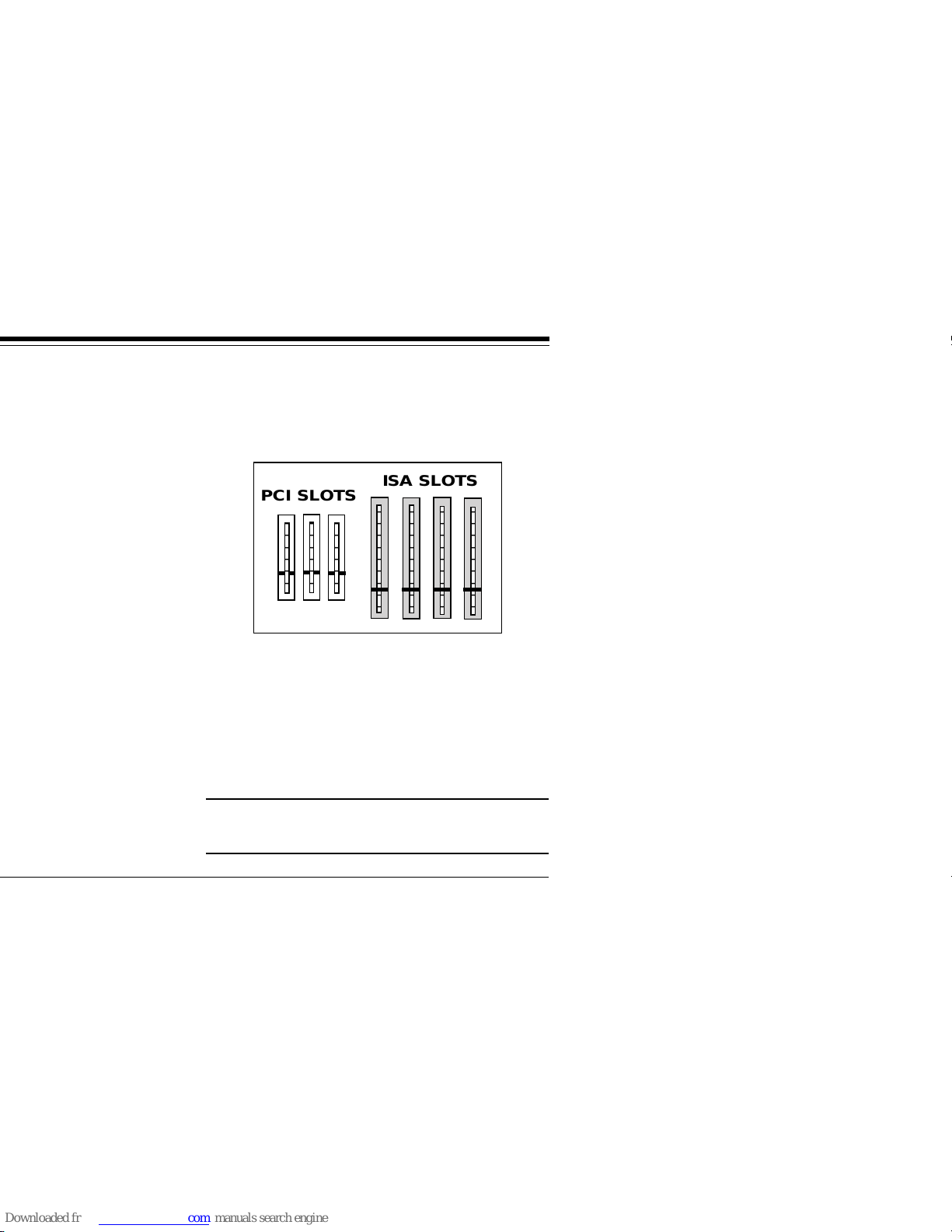
2. Select any available PCI-Bus expansion slot.
3. Remove the screw and the metal plate that
covers the external access to the slot you
have selected.
Remove any existing VGA/EGA card before
installing the Voyager 64.
PCI SLOTS
ISA SLOTS
11
7. Attach the appropriate monitor cable to the
Voyager 64.
8. Power up your system.
Physical installation is complete.
If you wish to enhance your display, turn to
the Display Driver section on page 18.
NOTE: Drivers are not required if the board
is used under DOS and Windows in standard
VGA modes. Drivers are required to run
high-resolution applications under DOS and
Windows.
EXPRESS Install

The Voyager 64 is based on a highly
integrated S3tm Trio64tm architecture. The
Trio64 contains an integrated RAMDAC and
Dual Clock Generator. The Trio64 has a 64 Bit
memory interface which provides 228 MB/
second bandwidth to support resolutions up
to 1600 x 1200, color depths up to 16M
colors, and refresh rates up to 75Hz noninterlaced.
Users of high performance CAD, Animation,
and 3D Modeling applications, will benefit
from the high system level performance
offered by the Voyager 64. Drivers are
provided for support of major GUI
applications such as AutoCAD and Windows.

13
• 1280 x 1024 X 256 Colors
• 1024 x 768 x 64K Colors
• 800 x 600 x 16M Colors
Maximum Resolution/Color Depth Supported
(interlaced).
• 1600 x 1200 x 256 Colors
Maximum Clock Frequencies
• Dot Clock 135 Mhz
• Memory Clock 57Mhz
Memory
• 64 Bit wide memory interface.
• 2MB of display memory
Product Overview

• VESA 1.2 BIOS with DPMS (Display Power
Management Signaling) monitor support.
Software Features
Drivers Provided for the following GUIs and
applications:
• AutoCAD V11 (DOS)
• AutoCAD V12 (DOS)
• MicroStation 4.0
• MicroStation 5.0
• Windows 3.1/3.11
Windows NT 3.5 and Windows 95 come with
built-in support for the S3 Trio64 on which the
Voyager 64 is based.

15
Monitor Compatibility
The Voyager 64 board is compatible with VGA
Color and monochrome analog monitors. TTL
monochrome monitors with 9-pin connectors
are NOT compatible with the Voyager 64. It is
also compatible with Multiple Frequency
Monitors, provided the proper 15-pin cable
adapter is used with the monitor and the
monitor is set to analog.
Check your monitor manual and the video
mode table in Appendix C to determine the
modes supported by your monitor.
Product Overview

System Compatibility
Most systems with PCI Local Bus slots are
compatible with the Voyager 64. If you are
uncertain, refer to your system’s guide to
operation or check with the dealer or
manufacturer of your computer. The Voyager
64 board is compatible with the IBM Video
Graphics Array (VGA) and Enhanced Graphics
Adapter (EGA) standards.

17
○ ○ ○ ○ ○ ○ ○ ○ ○ ○
○ ○ ○ ○ ○ ○ ○ ○ ○ ○
MAIN CHIP SET
FEATURE
CONNECTOR
Product Overview
VIDEO
BIOS
VIDEO
DRAM
DB-15
VGA
CONNECTOR

Highlights include:
• 1600 x 1200 resolution in 256 colors
(interlaced)
• 1024 x 768 resolution in 65,536 colors
• 800 x 600 resolution in 16.7 million colors
• 640 x 480 resolution in 16.7 million colors
If you intend to use your Voyager 64 in
standard VGA modes, you DO NOT need to
install any of these drivers.

19
Installing the Display Drivers
For DOS-only Users
For Windows users, turn to the next page.
• Make sure the Voyager 64 is present
(physically installed) BEFORE installing any
drivers.
• Insert the Voyager driver diskette into your
system drive A: (or B:).
• Type A:\INSTALL (or B:\INSTALL) at a DOS
prompt and follow all on-screen
instructions.
Display Drivers
Screen Saver

Windows 3.1/3.11
The Voyager driver diskette contains drivers
for both DOS and Windows. Make sure
Windows is already installed on your system.
The Windows install can also install drivers for
DOS applications.
1. Put the disk labeled “Voyager Driver
Diskette” into your A: or B: drive.
2. Start Windows
3. From the Program Manager screen, select
File, then Run.
4. In the Command Line box, type A:SETUP or
B:SETUP, then select OK.

21
the README.TXT file in the C:\SVGP64
subdirectory. Installation is complete.
Display Drivers

Windows NT (3.5+)
Do the following to get started when installing
the Voyager 64 with the Windows NT
operating system:
Select the Display icon from the Control Panel,
then Settings, then Change Display Type.
Select S3 as the compatible driver type.
If you require additional assistance, consult
your Windows NT documentation.

23
to your AUTOEXEC.BAT. Choose YES if you
want to use the new refresh rate every time
you turn on your system.
NOTE: The refresh rate set with Vrefresh has
no effect when using Windows.
Display Drivers

Using the FCON Utility
This DOS-based utility allows you to enable or
disable the board’s feature connector. In order
to maintain VESA compatibility when using the
feature connector, only 1MB video modes are
supported.
Instructions for FCON are provided on-screen.

25
• Verify that switch settings and/or jumpers
are properly set on your motherboard. Refer
to compatibility requirements.
• Confirm that your computer and monitor are
plugged in. Check all power cables.
PROBLEM
The computer seems to boot, but there is no
display.
POSSIBLE SOLUTION
• Check all cable and power cable connections
and verify that the monitor is powered on.
• Adjust brightness and contrast controls
correctly.
Troubleshooting

• Make sure your Voyager 64 is properly
installed in a PCI slot.
PROBLEM
Your monitor’s display appears somewhat
distorted when running a graphics
application
POSSIBLE SOLUTION
• Set the vertical hold properly on your
monitor.
• Ensure that your current graphics application
software has been properly installed.
• Ensure that your monitor is capable of
displaying the graphics mode you are using.
Refer to your monitor specifications and
Appendix C.

27
another system, it is likely the problem lies
elsewhere.
• Ensure that your computer is compatible with
the PCI 2.0 Local Bus specifications.
• Ensure that your computer is completely
compatible with IBM standards. Some
machines do not support IBM-standard video
BIOS requirements.
PROBLEM
You are experiencing difficulty installing the
Voyager 64 on a network.
POSSIBLE SOLUTION
• Generally speaking, when configuring a
network system avoid the following areas the
Voyager 64 occupies: Memory addresses
Troubleshooting
network documentation or network software
vendor if you require additional assistance in
this area.
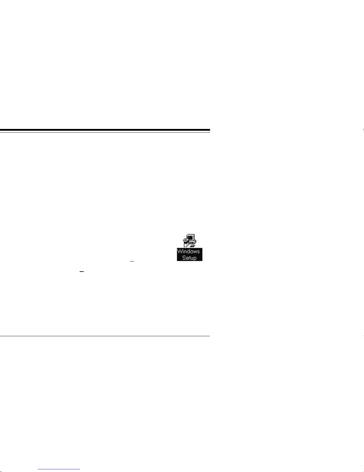
PROBLEM
You
want to adjust your display resolution
with Windows Setup.
REMEDY
Go to the Main Program Group
and select the Windows Setup
icon. Next, select Options, then
Change System Settings. Click on the Down
Arrow next to the Display bar. Here you may
select an alternate display resolution (for
SVGP64). Once you choose an alternate
setting, you will be instructed to re-start
Windows. Follow all on-screen instructions.

29
Signal Pin
Red 1
Green 2
Blue 3
Not used 4
Ground 5
Red Return 6
Green Return 7
Blue Return 8
Not used 9
Ground 10
Not used 11
DDC Data 12
Horizontal Sync 13
Vertical Sync 14
Not used 15
Pin-Out Assignments for the DB15 Video Cable Connector
Technical Specifications

Signal Feature Connector Pin
Pixel Data 0 2
Pixel Data 1 4
Pixel Data 2 6
Pixel Data 3 8
Pixel Data 4 10
Pixel Data 5 12
Pixel Data 6 14
Pixel Data 7 16
Pixel clock 18
Blanking 20
Horz. Sync 22
Vert. Sync 26
ground 1
ground 3
ground 5

31
For additional information see the Auxiliary
Video Connector description in the IBM PS/2
Hardware Technical Reference Manual.
Video Modes
7
9
11

In this case, you must either lower the
resolution to one that can be supported, or
lower the refresh rate. Refer to your monitor
owner’s manual.

33
Video Modes


35
Video Modes


37
accordance with the instructions, may cause harmful
interference to radio or television reception. However,
there is no guarantee that interference will not occur in a
particular installation. If this equipment does cause
harmful interference to radio or television reception, which
can be determined by turning the equipment off and on,
the user is encouraged to try to correct the interference by
one or more of the following measures:
• Reorient or relocate the receiving antenna.
• Increase the separation between the equipment and the
receiver.
• Connect the equipment into an outlet on a circuit
different from that to which the receiver is connected.
• Consult the dealer or an experienced radio/TV technician
for help.
CHANGES OR MODIFICATIONS TO THIS EQUIPMENT NOT
EXPRESSLY APPROVED BY THE MANUFACTURER COULD
VOID YOUR AUTHORITY TO OPERATE THE EQUIPMENT.
FCC Compliance

NOTE: CALLING TECHNICAL SUPPORT
WITHOUT COMPLETE AND ACCURATE
INFORMA TION CONCERNING YOUR PROBLEM
MA Y BE BOTH TIME-CONSUMING AND
FRUSTRA TING FOR YOU.
1. When calling Boca Research Technical Support,
have the following information available:
• Exact board name/product code and board part
number
• Software/driver revision level
• Computer manufacturer
• Computer model
• Peripherals in the system
• Operating system and version
• Contents of system’s CONFIG.SYS

39
3. Refer to the Warranty Statement if the product
is covered under the five-year Boca Research,
Inc. Limited Warranty.
4. Certain parts will not be covered under the Boca
Research, Inc. Limited Warranty. Dealer installed
parts are warranted by the dealer. Parts which
you have installed yourself are covered only by
the supplier’s warranties. In these cases, Boca
Research, Inc. can identify which parts are
defective, but will not replace such parts until
specific written authorization is received from
you. The cost of parts and labor involved in
making such repairs will be billed to you C.O.D.
5. When sending a board to Boca Research, Inc.
for repairs, please be sure to include the Voyager
64 board, your return street address (for UPS
purposes), phone number, and the RMA number
mentioned above.
Servicing Your Boca Product


41
Products which require Limited Warranty service during
the warranty period should be delivered to BRI at the
address in the Appendix (Servicing Your Boca Product)
with proof of purchase, copy of canceled check (if any),
and the Return Merchandise Authorization (RMA) number
provided by BRI Technical Support. Refer to the Appendix
in this manual. Replacement parts or complete products
will be furnished on an exchange basis only. Replaced
parts and/or products become the property of BRI.
If the returned product is sent by mail, the purchaser
agrees to prepay shipping charges, insure the product or
assume the risk of loss or damage which may occur in
transit, and to use a shipping container equivalent to the
original packaging. BRI does not make any warranties in
respect to the product, either expressed or implied,
including no implied warranties of merchantability or
fitness for a particular purpose, except as expressly
provided in this agreement. If any labor, repair, or parts
replacement is required because of accident, negligence,
misuse, theft, vandalism, fire, water or other peril; or
because of conditions outside of specifications, including,
but not limited to, electrical power, temperature, humidity
or dust; or by moving, repair relocation, or alteration not
Warranty


43
5. BRI remains the copyrighted owner of the Voyager 64
software. The ONLY rights given to the licensee are those
which have been provided for under this agreement.
6. UNDER NO CIRCUMSTANCES WILL BRI BE HELD LIABLE
IN ANY WAY TO ANY PURCHASER FOR DAMAGES, LOST
REVENUE, LOST WAGES OR FOR ANY OTHER
INCIDENTAL OR CONSEQUENTIAL DAMAGES OF ANY
KIND WHETHER COVERED UNDER THIS AGREEMENT OR
OTHERWISE. THE Voyager 64 SOFTWARE IS NOT
WARRANTED IN ANY WAY AND ITS USE IS THE SOLE
RESPONSIBILITY OF THE LICENSEE FREE FROM ANY
EXPRESSED OR IMPLIED WARRANTIES OF
MERCHANTABILITY AND FITNESS FOR A PARTICULAR
PURPOSE.
7. BRI provides a five year warranty for the media on which
the Voyager 64 software is furnished. This warranty is
limited to defects in materials and workmanship; it does
not cover the functions provided by the Voyager 64
software. This license is subject to termination upon
breach of this agreement. The Voyager 64 software and
any copies must be destroyed or returned to Boca
Research, Inc.
8. BRI reserves the right to make modifications to the
software without any prior notice.
9. This license is governed by the laws of the state of Florida.
Software License Agreement

BIOS. Basic Input Output System. Provides
fundamental services required for the operation of
a computer. Permanently present in the machine,
these routines are generally stored in ROM (Read
Only Memory). The system board contains a ROM
BIOS to support all of its standard functions. The
Voyager 64 also has a BIOS for display features.
Bit Block Transfer. A method of holding a block of
graphics, such as Windows dialogue box, in
memory so that it can be moved and redrawn
quickly by memory-to-memory operations.
CGA. Color Graphics Adapter. Medium resolution
IBM graphics standard capable of displaying 640 x
200 pixels in 2 colors, or 320 x 200 pixels in 4
colors.
Color Monitor. Any CGA, EGA, VGA color, or
multiple frequency monitor.

45
Extended EGA. Offered by proprietary chip sets on
non-IBM adapter cards with 640 x 480 resolution
or better.
Feature Connector. Used by graphics adapters to
give compatibility with VGA text and graphics
codes for use with multi-media applications.
GUI. Graphical User Interface.
Flicker. The wavering or unsteady image on some
monitors. A major cause can be a low refresh rate.
Hardware Graphics Cursor. Provides a faster
method of displaying/moving a cursor (GUI arrow)
on the screen. The video adapter’s main chipset
controls this function which resides in system
memory, as opposed to slower handling by the
application software.
Glossary

MDA. Monochrome Display Adapter. Early IBM
Video display board designed for use with IBM
monochrome text standard.
Monochrome Monitor. A TTL monitor which can
display only 2 colors (generally green/black or
amber/black).
Multiple Frequency Monitor. Monitor capable of
displaying video signals over a wide range of
horizontal scan frequencies. This may include a
horizontal capture range from 5.5KHz to 35KHz or
wider. Examples of monitors in this class are the
NEC MultiSync and the Sony Multiscan. The
Multiscan has a wide horizontal scan capture range
which enables it to display monochrome signals.
Palette. The range of colors from which you can
select the actual colors that the video adapter will
display simultaneously. Pixel. A single dot on the
CRT display. This word is derived from the words
‘picture’ and ‘element’.

47
TTL. Transistor-Transistor Logic; a fast,
reasonable-cost type of integrated circuit used in
some monitors.
TTL Monitor. Video and synchronization signals
(all digital) are on separate lines and have TTL
compatible voltage levels.
VESA. Video Electronics Standards Association.
VGA. (Video Graphics Array) Analog graphics
standard introduced with the IBM PS/2 series.
Backwards compatible with EGA at the BIOS level,
but provides higher resolutions. Supports a
maximum resolution of 640 x 480 pixels in 16
colors out of a palette of 262,144 colors.
Glossary


49
C
Cables and power cords 11
Clock Frequencies 13
Color Depth 13
Connector Information 29
D
Damaged or Missing Items 4-5, 8
DB15 cable 16, 29
Dimensions 30
Display Data Channel 13
Display Drivers 18-24
Display memory 12
Distorted display 26
DOS-only users 19
DPMS (Display Power Management
signaling) support 13
Drivers 11, 15, 18, 19
Dual Clock Generator 12

I
IBM VGA compatible 8
IBM Video Graphics Array 16
IBM-standard video BIOS
requirements 27
IBM’s analog monitors 19
Installing the Voyager 64 8-11
M
Maximum Resolution (interlaced) 13
Maximum Resolution (non-interlaced) 13
Memory 13
Memory addresses 27-28
Microsoft Windows 19, 20-21
Microstation PC 19
Monitor cable 26
Monitor compatibility 15
Multiple frequency monitors 15, 19, 26

51
R
RAMDAC 12
README.TXT file 18
Return Merchandise Authorization (RMA)
number 39
S
Servicing Your Boca Product 38-40
Size adjustment controls 27
Software Features 14
Software License Agreement 43
Standard ISA slot 10
Standard VGA modes 18
Standard VGA monitors 19
SVGP64 Utilities 19
System compatibility 16
System requirements 17

Vrefresh without a Mouse 24
W
Warranty 41-42
Windows 95 19, 22
Windows NT 19, 22

53


55

Manual Part # 9465
Rev. 1.0
 Loading...