

Page 1

8-PORT
E
THERNET
BOCA NET-8 ETHERNET KIT
N
ETWORK
Page 2

22
2
22
BOCA NETBOCA NET
BOCA NET
BOCA NETBOCA NET
-8 Ethernet Kit-8 Ethernet Kit
-8 Ethernet Kit
-8 Ethernet Kit-8 Ethernet Kit
Page 3
33
3
33
BefBef
Bef
BefBef
The product you have purchased is designed
to be easily installed with most IBM PC or
compatible systems. Many products have
large, easy-to-read legends to allow for the
easy configuring of the product. This
installation manual contains detailed
instructions. Most included software has automatic installation
programs to place the software correctly onto your computer.
However, as all computers are configured differently, you may
be required to perform some basic DOS or Windows tasks. If
you are not familiar with basic DOS commands such as DIR,
CD, or EDIT, you should check your DOS manual, or seek
assistance from you local computer dealer to install the
product.
oror
or
oror
e e
YY
ou Begou Beg
e
Y
ou Beg
e e
YY
ou Begou Beg
in yin y
in y
in yin y
our Installaour Installa
our Installa
our Installaour Installa
tiontion
tion
tiontion
HoHo
w to get w to get
Ho
w to get
HoHo
w to get w to get
familiar with your system and how this product should be
installed. Many dealers have customer service and technical
support programs, with varying levels of support offered,
depending on your needs and computer knowledge.
contact the dealer first whenever a prcontact the dealer first whenever a pr
contact the dealer first whenever a pr
contact the dealer first whenever a prcontact the dealer first whenever a pr
TT
echnical echnical
T
echnical
TT
echnical echnical
The dealer that you purchased this
product or your computer from is the first
place you should go for technical
assistance. The dealer is usually the most
qualified source of help, and is most
AssistanceAssistance
Assistance
AssistanceAssistance
oblem occurs.oblem occurs.
oblem occurs.
oblem occurs.oblem occurs.
PleasePlease
Please
PleasePlease
Page 4

44
4
44
If yIf y
our Dealer Can’our Dealer Can’
If y
our Dealer Can’
If yIf y
our Dealer Can’our Dealer Can’
If you can’t get assistance from your dealer, the manufacturer
provides varying levels of technical assistance as summarized
on the opposite page.
The Standard Free Technical Support number is for quick
answers to specific inquiries on product features and technical
t t
Assist yAssist y
t
Assist y
t t
Assist yAssist y
ouou
ou
ouou
questions (call
access to technical support representatives is provided on a
limited basis. If you require immediate attention or in-depth
help with the installation of the product, please call our 900priority support number for service. This number gives you
immediate access to senior-level technicians. The number is
900-555-4900900-555-4900
900-555-4900. You will be charged $2.00 per minute. The
900-555-4900900-555-4900
charges will appear on your next phone bill.
Damaged or Missing ItemsDamaged or Missing Items
Damaged or Missing Items
Damaged or Missing ItemsDamaged or Missing Items
We use many world-class quality assurance programs to ensure
the product you purchased is of the highest caliber. Sometimes,
however, a component may be missing from the box, or is
damaged or corrupt in some way. If this happens, immediately
return the entire package to your place of purchase so you may
561-241-8088561-241-8088
561-241-8088; M-F, 8 am to 6:30 pm EST). Direct
561-241-8088561-241-8088
exchange it for a new one. Your dealer should be able to
provide you with an exchange far more quickly than by
contacting us directly. If for some reason you are unable to
return the product directly to its place of purchase, refer to the
“Servicing Your Product” and “Warranty” sections in this
manual for instructions.
BOCA NETBOCA NET
BOCA NET
BOCA NETBOCA NET
-8 Ethernet Kit-8 Ethernet Kit
-8 Ethernet Kit
-8 Ethernet Kit-8 Ethernet Kit
Page 5
55
5
55
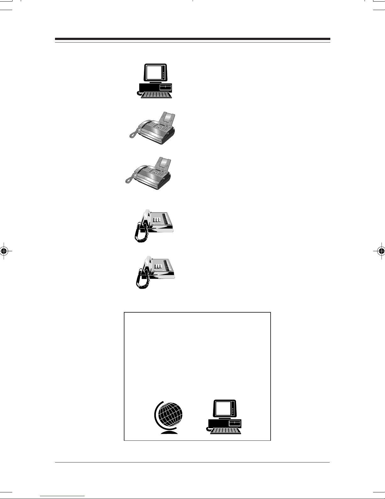
Boca BBSBoca BBS
Boca BBS
Boca BBSBoca BBS
561-241-1601561-241-1601
561-241-1601
561-241-1601561-241-1601
AutomatedAutomated
Automated
AutomatedAutomated
1
2
4
3
5
7
6
8
9
1
2
4
3
5
7
6
8
9
Fax RetrievalFax Retrieval
Fax Retrieval
Fax RetrievalFax Retrieval
SystemSystem
System
SystemSystem
561-995-9456561-995-9456
561-995-9456
561-995-9456561-995-9456
TT
echnicalechnical
T
echnical
TT
echnicalechnical
Support FaxSupport Fax
Support Fax
Support FaxSupport Fax
561-997-2163561-997-2163
561-997-2163
561-997-2163561-997-2163
Standard FrStandard Fr
Standard Fr
Standard FrStandard Fr
TT
echnical Supportechnical Support
T
echnical Support
TT
echnical Supportechnical Support
561-241-8088561-241-8088
561-241-8088
561-241-8088561-241-8088
Priority ServicePriority Service
Priority Service
Priority ServicePriority Service
900-555-4900900-555-4900
900-555-4900
900-555-4900900-555-4900
($2 per minute)($2 per minute)
($2 per minute)
($2 per minute)($2 per minute)
On-Line SupporOn-Line Suppor
On-Line Suppor
On-Line SupporOn-Line Suppor
CompuServeCompuServe
CompuServe
CompuServeCompuServe
InternetInternet
Internet
InternetInternet
email:email:
email:
email:email:
on the Won the W
on the W
on the Won the W
http://wwwhttp://www
http://www
http://wwwhttp://www
::
:
::
: GO BOCA: GO BOCA
: GO BOCA
: GO BOCA: GO BOCA
orld World W
orld W
orld World W
ide WEB:ide WEB:
ide WEB:
ide WEB:ide WEB:
.bocaresearch.com.bocaresearch.com
.bocaresearch.com
.bocaresearch.com.bocaresearch.com
t!t!
t!
t!t!
eeee
ee
eeee
Page 6

66
6
66
ContentsContents
Contents
ContentsContents
Part I: Part I:
Part I:
Part I: Part I:
Part II: Part II:
Part II:
Part II: Part II:
Section One: InstallationSection One: Installation
Section One: Installation
Section One: InstallationSection One: Installation
Section Two: Network ConfigurationSection Two: Network Configuration
Section Two: Network Configuration
Section Two: Network ConfigurationSection Two: Network Configuration
2.1 Small Stand-Alone Network2.1 Small Stand-Alone Network
2.1 Small Stand-Alone Network
2.1 Small Stand-Alone Network2.1 Small Stand-Alone Network
2.2 Cascaded Network2.2 Cascaded Network
2.2 Cascaded Network
2.2 Cascaded Network2.2 Cascaded Network
Section Three: Cabling CharacteristicsSection Three: Cabling Characteristics
Section Three: Cabling Characteristics
Section Three: Cabling CharacteristicsSection Three: Cabling Characteristics
3.1 Cable Type3.1 Cable Type
3.1 Cable Type
3.1 Cable Type3.1 Cable Type
3.2 Pin Assignments3.2 Pin Assignments
3.2 Pin Assignments
3.2 Pin Assignments3.2 Pin Assignments
3.3 Crossover Function3.3 Crossover Function
3.3 Crossover Function
3.3 Crossover Function3.3 Crossover Function
3.4 Straight-Through Wiring3.4 Straight-Through Wiring
3.4 Straight-Through Wiring
3.4 Straight-Through Wiring3.4 Straight-Through Wiring
Introduction and Package ContentsIntroduction and Package Contents
Introduction and Package Contents
Introduction and Package ContentsIntroduction and Package Contents
The BOCA NET-8 HubThe BOCA NET-8 Hub
The BOCA NET-8 Hub
The BOCA NET-8 HubThe BOCA NET-8 Hub
........................................................................
....................................
........................................................................
..................................
.................
..................................
........................................................................
....................................
........................................................................
....................................................................................................
..................................................
....................................................................................................
..............................................................................
.......................................
..............................................................................
......................................................................
...................................
......................................................................
................................................
........................
................................................
..........
.....
..........
..........................
.............
..........................
......................
...........
......................
88
8
88
1414
14
1414
1515
15
1515
1515
15
1515
1616
16
1616
1818
18
1818
1818
18
1818
1818
18
1818
1919
19
1919
2020
20
2020
3.5 Crossover Wiring3.5 Crossover Wiring
3.5 Crossover Wiring
3.5 Crossover Wiring3.5 Crossover Wiring
Part III:Part III:
Part III:
Part III:Part III:
Section One: InstallationSection One: Installation
Section One: Installation
Section One: InstallationSection One: Installation
1.1 Inserting the Adapter1.1 Inserting the Adapter
1.1 Inserting the Adapter
1.1 Inserting the Adapter1.1 Inserting the Adapter
1.2 Adapter Configuration1.2 Adapter Configuration
1.2 Adapter Configuration
1.2 Adapter Configuration1.2 Adapter Configuration
BOCA NETBOCA NET
BOCA NET
BOCA NETBOCA NET
The 10Base-T Network Card The 10Base-T Network Card
The 10Base-T Network Card
The 10Base-T Network Card The 10Base-T Network Card
Single BoardSingle Board
Single Board
Single BoardSingle Board
Multiple BoardMultiple Board
Multiple Board
Multiple BoardMultiple Board
-8 Ethernet Kit-8 Ethernet Kit
-8 Ethernet Kit
-8 Ethernet Kit-8 Ethernet Kit
................................................................................................
................................................
................................................................................................
..........................................................................................
.............................................
..........................................................................................
............................................................................
......................................
............................................................................
............................................................................
......................................
............................................................................
................................................................
................................
................................................................
............................................................
..............................
............................................................
2020
20
2020
2121
21
2121
2222
22
2222
2525
25
2525
2525
25
2525
2525
25
2525
Page 7

77
7
77
Section Two: ConfigurationSection Two: Configuration
Section Two: Configuration
Section Two: ConfigurationSection Two: Configuration
2.1 Driver Support2.1 Driver Support
2.1 Driver Support
2.1 Driver Support2.1 Driver Support
2.2 Installation Notes2.2 Installation Notes
2.2 Installation Notes
2.2 Installation Notes2.2 Installation Notes
2.3 Configuration2.3 Configuration
2.3 Configuration
2.3 Configuration2.3 Configuration
2.4 Windows 95 Driver Installation2.4 Windows 95 Driver Installation
2.4 Windows 95 Driver Installation
2.4 Windows 95 Driver Installation2.4 Windows 95 Driver Installation
Part IVPart IV
Part IV
Part IVPart IV
1.1 BOCA NET-8 Hub1.1 BOCA NET-8 Hub
1.1 BOCA NET-8 Hub
1.1 BOCA NET-8 Hub1.1 BOCA NET-8 Hub
1.2 10Base-T Network Card1.2 10Base-T Network Card
1.2 10Base-T Network Card
1.2 10Base-T Network Card1.2 10Base-T Network Card
Part VPart V
Part V
Part VPart V
::
T T
rr
oubleshootingoubleshooting
:
T
r
oubleshooting
T T
rr
oubleshootingoubleshooting
::
::
Appendices Appendices
:
Appendices
Appendices Appendices
::
........................................................................................
............................................
........................................................................................
............................................................................................
..............................................
............................................................................................
..................................................................
.................................
..................................................................
..............................................................................
.......................................
..............................................................................
........................................................................
....................................
........................................................................
............................
..............
............................
....................................................
..........................
....................................................
2626
26
2626
2626
26
2626
2626
26
2626
3232
32
3232
3232
32
3232
3535
35
3535
3838
38
3838
Appendix A: SpecificationsAppendix A: Specifications
Appendix A: Specifications
Appendix A: SpecificationsAppendix A: Specifications
Appendix B: Pin AssignmentsAppendix B: Pin Assignments
Appendix B: Pin Assignments
Appendix B: Pin AssignmentsAppendix B: Pin Assignments
Appendix C: Appendix C:
Appendix C:
Appendix C: Appendix C:
Appendix D: Installing Boot ROMsAppendix D: Installing Boot ROMs
Appendix D: Installing Boot ROMs
Appendix D: Installing Boot ROMsAppendix D: Installing Boot ROMs
Appendix E: FCC ComplianceAppendix E: FCC Compliance
Appendix E: FCC Compliance
Appendix E: FCC ComplianceAppendix E: FCC Compliance
Appendix F: Servicing Your Boca ProductAppendix F: Servicing Your Boca Product
Appendix F: Servicing Your Boca Product
Appendix F: Servicing Your Boca ProductAppendix F: Servicing Your Boca Product
Appendix G: WarrantyAppendix G: Warranty
Appendix G: Warranty
Appendix G: WarrantyAppendix G: Warranty
NET.CFG Options for NetWareNET.CFG Options for NetWare
NET.CFG Options for NetWare
NET.CFG Options for NetWareNET.CFG Options for NetWare
....................................................................................
..........................................
....................................................................................
................................................................
................................
................................................................
..........................................................
.............................
..........................................................
....................
..........
....................
......................................
...................
......................................
......................................................
...........................
......................................................
..........
.....
..........
4242
42
4242
4444
44
4444
4545
45
4545
4848
48
4848
5050
50
5050
5151
51
5151
5353
53
5353
Page 8

88
8
88
PP
ARAR
AR
ARAR
T I: IntrT I: Intr
T I: Intr
T I: IntrT I: Intr
P
PP
Congratulations on purchasing the BOCA NET-8 Ethernet
kit, which provides everything you need for your network
in one box. Our compact hub, which fits conveniently on
the corner of a desk is fully compliant with IEEE 802.3
standards. Its highly integrated single-chip solution
constantly monitors signal quality ensuring reliability of
your network reliability.
oduction and Poduction and P
oduction and P
oduction and Poduction and P
acac
kage Contentskage Contents
ac
kage Contents
acac
kage Contentskage Contents
In addition, your 10Base-T Ethernet cards get you started
in connecting your ISA bus-based (or compatible) systems
to an Ethernet network. The 10Base-T card features an
RJ45 connector for easy connection to the supplied 8-port
via twisted-pair connector cables from Belkin (supplied).
BOCA NETBOCA NET
BOCA NET
BOCA NETBOCA NET
-8 Ethernet Kit-8 Ethernet Kit
-8 Ethernet Kit
-8 Ethernet Kit-8 Ethernet Kit
Page 9

FF
eaea
turtur
F
ea
FF
eaea
• High-performance, highly integrated one-chip solution from
Advanced Micro Devices.
• The 8-port concentrator allows you to connect up to eight nodes
using unshielded twisted-pair cabling.
• A crossover switch for “cascading” multiple units to support
flexible growth.
• Status LEDs monitor status and operation at all times.
• Automatic partitioning disables ports that experience collisions
and automatically reconnects those ports when the error
es of the BOCes of the BOC
tur
es of the BOC
turtur
es of the BOCes of the BOC
A NETA NET
A NET
A NETA NET
-8:-8:
-8:
-8:-8:
99
9
99
Part I: Introduction and
Package Contents
condition is cleared
FF
eaea
turtur
F
ea
FF
eaea
• Compliant with ISO/ANSI IEEE 802.3 specifications
• High-performance, highly integrated one-chip solution
• On-board support for connecting to a 10Base-T network.
• Designed to work with 286, 386, 486, and Pentium-based
systems.
• Plug and Play compatible (ISA Plug and Play, v. 1.0a)
• Full-duplex capability with a full-duplex hub (not supplied)
• Jumperless adapter—all features such as interrupt channel and
I/O address are software-selectable.
• Easy installation and maintenance.
• Uses existing NE2000 drivers—no need to install new drivers.
es of the 10Base-T Netwes of the 10Base-T Netw
tur
es of the 10Base-T Netw
turtur
es of the 10Base-T Netwes of the 10Base-T Netw
.
oror
k Cark Car
or
k Car
oror
k Cark Car
d:d:
d:
d:d:
• Low-cost solution for networks requiring 10Base-T or 10Base2
connection.
• One link/receive (GREEN) status LED indicator and one
transmit (RED) status LED indicator.
• NE2000/NE2000+ compatible.
IntrIntr
oductionoduction
Intr
oduction
IntrIntr
oductionoduction
Page 10

1010
10
1010
Functional DescrFunctional Descr
Functional Descr
Functional DescrFunctional Descr
The BOCA NET-8 is an implementation of an IEEE 802.3/
Ethernet repeater or hub. It provides eight 10Base-T ports in a
compact package. The BOCA NET-8 complies with the full set
of repeater basic functions as defined in section 9 of ISO 8802.3
(ANSI/IEEE 802.3c). These functions are defined below:
RepeaRepea
Repea
RepeaRepea
If any single network port senses the start of a valid packet on
its receive lines, then the BOCA NET-8 will re-transmit the
received data to all other enabled network ports.
Signal RegeneraSignal Regenera
Signal Regenera
Signal RegeneraSignal Regenera
When re-transmitting a packet, the BOCA NET-8 ensures that
the outgoing packet complies with the 802.3 specification in
ter Functionter Function
ter Function
ter Functionter Function
iption fiption f
iption f
iption fiption f
tiontion
tion
tiontion
or the BOCor the BOC
or the BOC
or the BOCor the BOC
A NETA NET
A NET
A NETA NET
-8-8
-8
-8-8
terms of preamble structure, voltage amplitude, and timing
characteristics.
JJ
aa
bber Locbber Loc
J
a
bber Loc
JJ
aa
bber Locbber Loc
The BOCA NET-8 implements a built-in jabber protection
scheme to ensure that the network is not disabled due to the
transmission of excessively long data packets.
Collision HandlingCollision Handling
Collision Handling
Collision HandlingCollision Handling
The BOCA NET-8 will detect and respond to collision
conditions as specified in 802.3. It will also protect the network
from an excessive duration of, or frequent collisions by
“partitioning” the offending port from the rest of the network.
Once a port is partitioned, the data received from that port will
not be repeated. However, any other data on the network will
kup Prkup Pr
kup Pr
kup Prkup Pr
otectionotection
otection
otectionotection
be re-transmitted on that port.
BOCA NETBOCA NET
BOCA NET
BOCA NETBOCA NET
-8 Ethernet Kit-8 Ethernet Kit
-8 Ethernet Kit
-8 Ethernet Kit-8 Ethernet Kit
Page 11

1111
11
1111
If the collisions that cause the partitioning cease, the port will
be re-connected to the rest of the network.
The status of the partitioning scheme can be checked at any
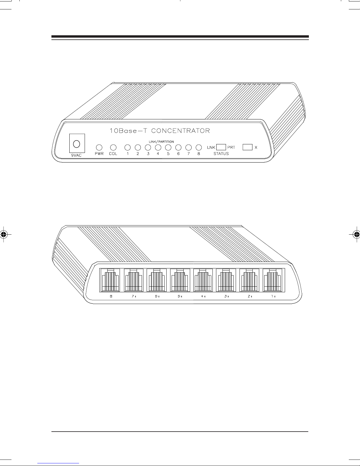
time by moving the LNK/PRT switch on the front of the BOCA
NET-8 to the PRT position. If any ports are currently
partitioned, the corresponding LED will come ON.
Link Link
Link
Link Link
The BOCA NET-8 implements the Link test function as
specified in the 802.3 10Base-T standard. It transmits Link test
pulses to any port after that port’s transmitter has been inactive
for a short period of time. The device connected to the port will
respond in the same manner.
The Link Status can be viewed on the LEDs of the BOCA NET-8
when the LNK/PRT switch is in the LNK position. If a
successful link has been established, the corresponding LED
will be ON.
PP
P
PP
The BOCA NET-8 automatically detects and adjusts to reversed
polarity of received data.
olarolar
olar
olarolar
TT
estest
T
est
TT
estest
ity Reity Re
ity Re
ity Reity Re
vv
v
vv
erer
er
erer
salsal
sal
salsal
IntrIntr
oductionoduction
Intr
oduction
IntrIntr
oductionoduction
Page 12
1212
12
1212
FRONT VIEW OF BOCA NET-8
BOCA NETBOCA NET
BOCA NET
BOCA NETBOCA NET
-8 Ethernet Kit-8 Ethernet Kit
-8 Ethernet Kit
-8 Ethernet Kit-8 Ethernet Kit
REAR VIEW OF BOCA NET-8
Page 13
1313
13
1313
Contents of Contents of
Contents of
Contents of Contents of
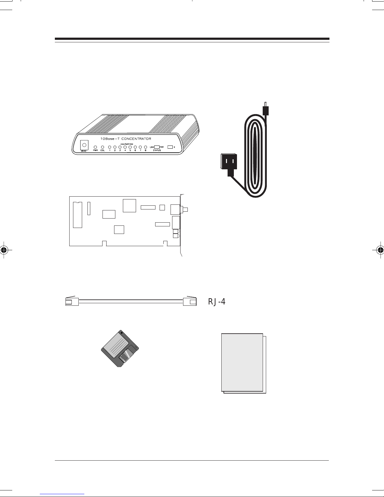
The BOCA NET-8 Hub
YY
our Pour P
Y
our P
YY
our Pour P
acac
ac
acac
kagekage
kage
kagekage
AC Power adapter
10Base-T Network Cards (2)
Driver diskette
RJ-45 Belkin 15’ cables (2)
8-PORT
E
THERNET
N
ETWORK
installation guide
Contents of Contents of
Contents of
Contents of Contents of
YY
our Pour P
Y
our P
YY
our Pour P
acac
ac
acac
kaka
ka
kaka
gg
g
gg
ee
e
ee
Page 14
1414
14
1414
PP
ARAR
P
AR
PP
ARAR
T II: T II:
T II:
T II: T II:
The BOCThe BOC
The BOC
The BOCThe BOC
A NETA NET
A NET
A NETA NET
-8 Hub-8 Hub
-8 Hub
-8 Hub-8 Hub
Section One: InstallaSection One: Installa
Section One: Installa
Section One: InstallaSection One: Installa
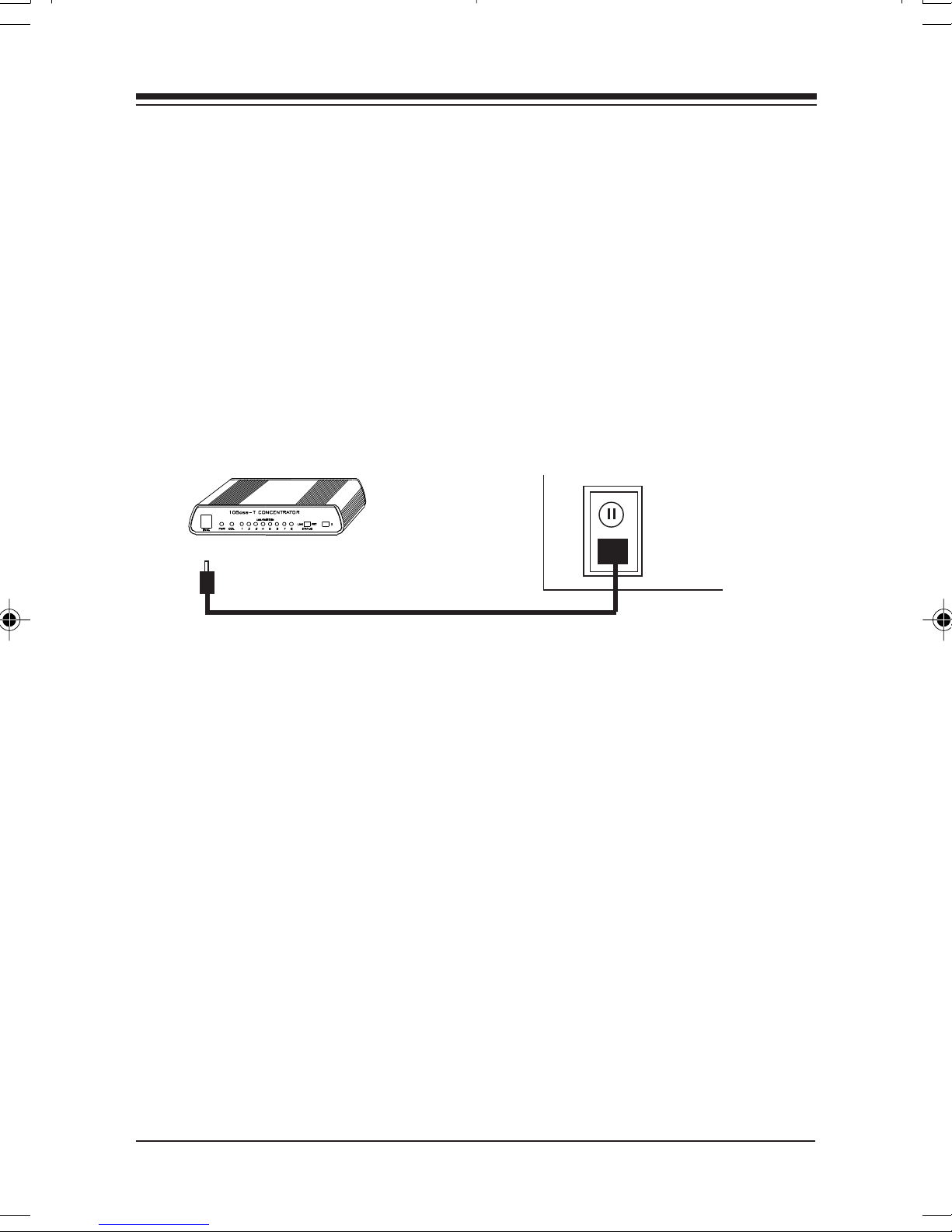
1. Connect the appropriate end of the power cord to the front of
the BOCA NET-8 (marked 9VAC) and insert the remaining
end to any conveniently accessible wall outlet.
2. Check the front panel LEDs. If the power (PWR) LED is not
tiontion
tion
tiontion
ON, turn to
BOCA NETBOCA NET
BOCA NET
BOCA NETBOCA NET
Part IV: Troubleshooting
-8 Ethernet Kit-8 Ethernet Kit
-8 Ethernet Kit
-8 Ethernet Kit-8 Ethernet Kit
.
Page 15
1515
15
1515
Section Section
Section
Section Section
The BOCA NET-8 is intended to connect multiple personal
computers (stand-alone) and/or other concentrators to an
Ethernet star topology network.
2.1 Small Stand-Alone Netw2.1 Small Stand-Alone Netw
2.1 Small Stand-Alone Netw
2.1 Small Stand-Alone Netw2.1 Small Stand-Alone Netw
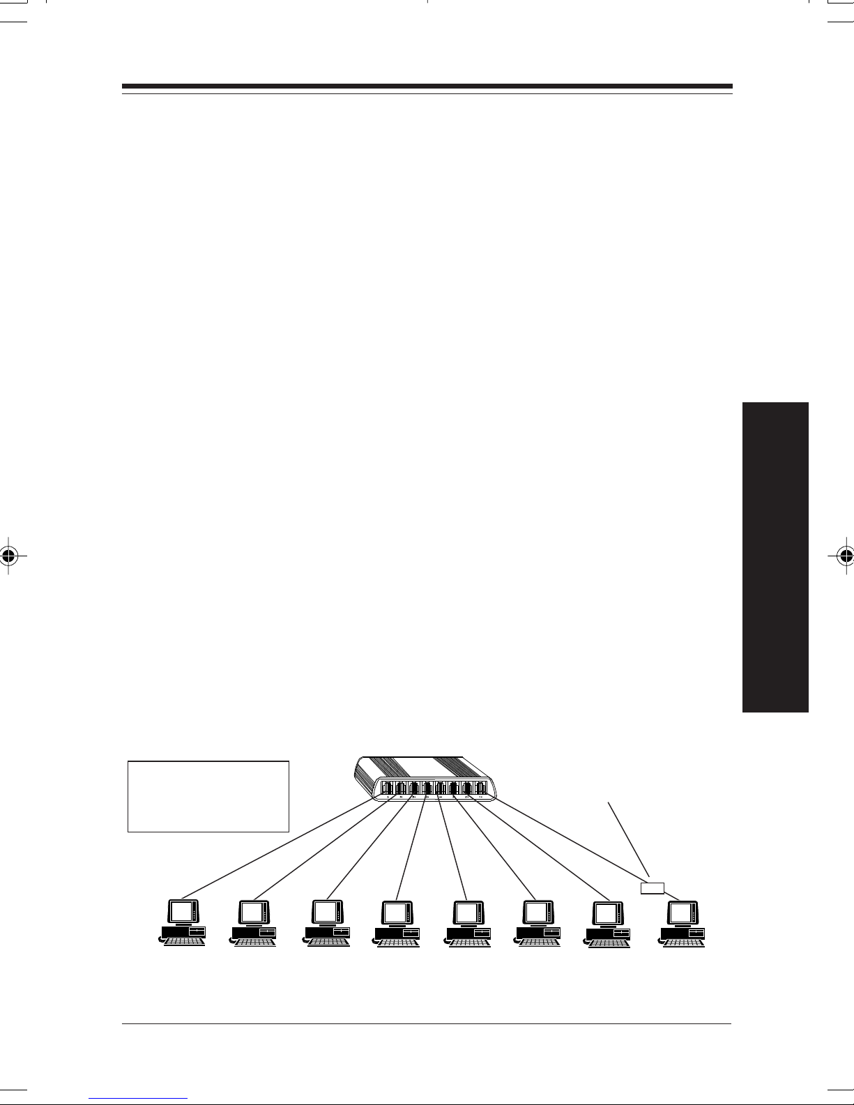
A single BOCA NET-8 can support a maximum of eight nodes,
one per port. Each device is connected directly to the twistedpair port (RJ-45 connector) via a twisted pair link segment (RJ45 cable).
If the Ethernet adapter in any given machine in the stand-alone
network does not have an RJ-45 connector, a transceiver may be
connected to interface the adapter to an RJ-45 connector. The
TT
ww
o: Netwo: Netw
T
w
o: Netw
TT
ww
o: Netwo: Netw
oror
k Confk Conf
or
k Conf
oror
k Confk Conf
oror
or
oror
kk
k
kk
iguraigura
igura
iguraigura
tiontion
tion
tiontion
P art II: The BOCA NET-8
Hub
other end of the transceiver is then connected to an RJ-45 port
on the concentrator with a twisted-pair link segment (RJ-45
cable). In the example below, work station number 8, with an
Ethernet adapter without an RJ-45 connector, requires a
transceiver.
meters (328 feet).meters (328 feet).
meters (328 feet).
meters (328 feet).meters (328 feet).
Twisted-Pair
Link Segments
(Max. 328'/100m)
Server
NOTE: Maximum RJ-45 cabling distance is 100NOTE: Maximum RJ-45 cabling distance is 100
NOTE: Maximum RJ-45 cabling distance is 100
NOTE: Maximum RJ-45 cabling distance is 100NOTE: Maximum RJ-45 cabling distance is 100
10Base-T
Transceiver
Workstations
NetwNetw
Netw
NetwNetw
ork Configurationork Configuration
ork Configuration
ork Configurationork Configuration
Page 16

1616
16
1616
2.2 Cascaded Netw2.2 Cascaded Netw
2.2 Cascaded Netw
2.2 Cascaded Netw2.2 Cascaded Netw
The star network may be expanded to a maximum of 91
stations through “cascading”. This amounts to 3 levels of
concentrators as shown on the next page. The
concentrator. One of its eight ports is connected to a network
card in the server. The remaining 7 ports are connected to 7
concentrators. This makes up the
concentrators have 7 ports available which are connected to 7
workstations for a total of
Seven ports on the remaining concentrator are connected to 7
additional concentrators. This makes up the
workstations may be connected to each of these concentrators
for a total of
Level 2 yield a total of 91 stations. See diagram on following
page.
49 stations on Level 349 stations on Level 3
49 stations on Level 3. 49 on Level 3 and 42 on
49 stations on Level 349 stations on Level 3
oror
kk
or
k
oror
kk
secondsecond
second level. Six of the 7
secondsecond
42 stations on Level 242 stations on Level 2
42 stations on Level 2.
42 stations on Level 242 stations on Level 2
thirdthird
third level. Seven
thirdthird
firstfirst
first is the main
firstfirst
When cascading from one BOCAWhen cascading from one BOCA
When cascading from one BOCA
When cascading from one BOCAWhen cascading from one BOCA
BOCABOCA
BOCA
BOCABOCA
non-X position Use a straight-through cable from port 8non-X position Use a straight-through cable from port 8
non-X position Use a straight-through cable from port 8
non-X position Use a straight-through cable from port 8non-X position Use a straight-through cable from port 8
on the first BOCAon the first BOCA
on the first BOCA
on the first BOCAon the first BOCA
second BOCAsecond BOCA
second BOCA
second BOCAsecond BOCA
NET NET
NET
NET NET
-8, set port 8 on the first BOCA-8, set port 8 on the first BOCA
-8, set port 8 on the first BOCA
-8, set port 8 on the first BOCA-8, set port 8 on the first BOCA
NET NET
NET
NET NET
NET NET
NET
NET NET
-8 to any one port (1-7) on the-8 to any one port (1-7) on the
-8 to any one port (1-7) on the
-8 to any one port (1-7) on the-8 to any one port (1-7) on the
-8.-8.
-8.
-8.-8.
NET NET
NET
NET NET
-8 to a second-8 to a second
-8 to a second
-8 to a second-8 to a second
NET NET
NET
NET NET
-8 to the-8 to the
-8 to the
-8 to the-8 to the
BOCA NETBOCA NET
BOCA NET
BOCA NETBOCA NET
-8 Ethernet Kit-8 Ethernet Kit
-8 Ethernet Kit
-8 Ethernet Kit-8 Ethernet Kit
Page 17
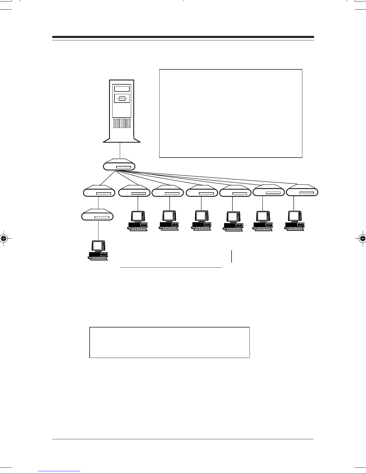
Server with
network
card
LEVEL 1
LEVEL 2
When connecting concentrators
there can be no more than 4
concentrators between any 2
workstations.
The diagram shown is the
maximum allowable configuration.
The system can have only one set
of Level 3 concentrators.
1717
17
1717
LEVEL 3
(7)
777777
(7 x 6 = 42)
(7 x 7 = 49)
NOTE: Maximum RJ-45 cabling distance is 100 meters (328 feet).NOTE: Maximum RJ-45 cabling distance is 100 meters (328 feet).
NOTE: Maximum RJ-45 cabling distance is 100 meters (328 feet).
NOTE: Maximum RJ-45 cabling distance is 100 meters (328 feet).NOTE: Maximum RJ-45 cabling distance is 100 meters (328 feet).
(91)
This is only a sample configuration.
Other configurations are possible.
NetwNetw
Netw
NetwNetw
ork Configurationork Configuration
ork Configuration
ork Configurationork Configuration
Page 18
1818
18
1818
Section Section
Section
Section Section
3.1 Ca3.1 Ca
3.1 Ca
3.1 Ca3.1 Ca
NOTE: If purchasing additional cables, read this section,NOTE: If purchasing additional cables, read this section,
NOTE: If purchasing additional cables, read this section,
NOTE: If purchasing additional cables, read this section,NOTE: If purchasing additional cables, read this section,
otherwise, continue with Part III.otherwise, continue with Part III.
otherwise, continue with Part III.
otherwise, continue with Part III.otherwise, continue with Part III.
Cable: UTP (Unshielded Twisted Pair)
Type: 100 Ohm UTP
Male Connector: 8-pin RJ-45
Distance: Maximum: 100m (328'); Minimum: .6m (2')
3.2 10Base-T Pin 3.2 10Base-T Pin
3.2 10Base-T Pin
3.2 10Base-T Pin 3.2 10Base-T Pin
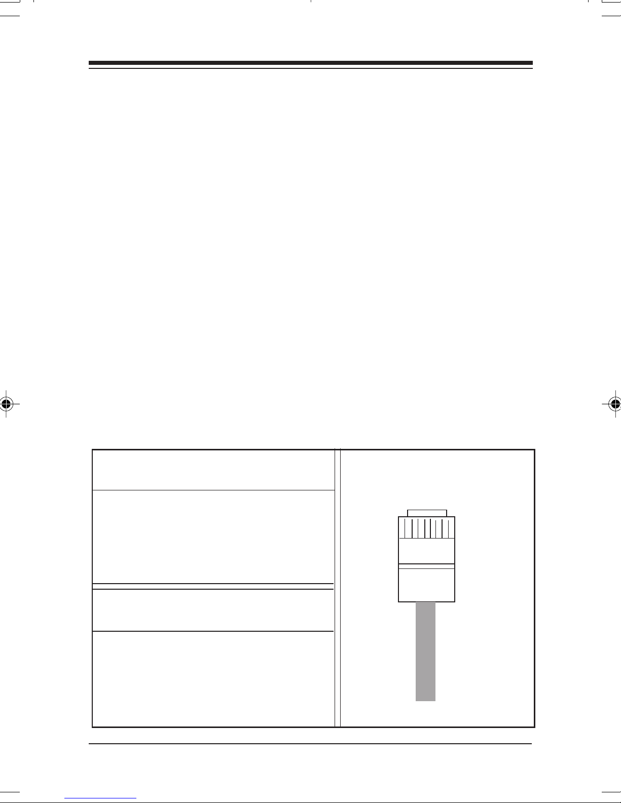
An Ethernet twisted pair link segment calls for two pairs of wires,
with each pair differentiated by color. Each twisted pair link
ThrThr
Thr
ThrThr
ble ble
ble
ble ble
ee: Caee: Ca
ee: Ca
ee: Caee: Ca
TT
ypeype
T
ype
TT
ypeype
bling Characterbling Character
bling Character
bling Characterbling Character
22-26 AWG (0.4-0.6 mm)
2 pairs minimum; category 3 or higher
AssignmentsAssignments
Assignments
AssignmentsAssignments
isticsistics
istics
isticsistics
segment must have an RJ-45 male connector attached to both ends.
Pins 1 and 2 on the RJ-45 connector are for transmitting data while
pins 3 and 6 are for receiving data. See chart below:
Looking into the RJ-45 connector
on the network card
RJ-45 Assignment
1 Tx+
2 Tx3 Rx+
6 Rx-
Looking into the RJ-45 connector
on the BOCA NET-8
RJ-45 Assignment
1 Rx+
2 Rx3 Tx+
6 Tx-
This is standard forThis is standard for
This is standard for
This is standard forThis is standard for
Ethernet devices . TheEthernet devices . The
Ethernet devices . The
Ethernet devices . TheEthernet devices . The
BOCABOCA
BOCA
BOCABOCA
over (except for port 8)over (except for port 8)
over (except for port 8)
over (except for port 8)over (except for port 8)
This is theThis is the
This is the
This is theThis is the
concentrator schemeconcentrator scheme
concentrator scheme
concentrator schemeconcentrator scheme
for Ports 1-7.for Ports 1-7.
for Ports 1-7.
for Ports 1-7.for Ports 1-7.
NET NET
-8 is crossed-8 is crossed
NET
-8 is crossed
NET NET
-8 is crossed-8 is crossed
Pin 1Pin 1
Pin 1
Pin 1Pin 1
88
-pin RJ45-pin RJ45
8
-pin RJ45
88
-pin RJ45-pin RJ45
ConnectorConnector
Connector
ConnectorConnector
Bottom ofBottom of
Bottom of
Bottom ofBottom of
Pin 8Pin 8
Pin 8
Pin 8Pin 8
plugplug
plug
plugplug
BOCA NETBOCA NET
BOCA NET
BOCA NETBOCA NET
-8 Ethernet Kit-8 Ethernet Kit
-8 Ethernet Kit
-8 Ethernet Kit-8 Ethernet Kit
Page 19

1919
19
1919
* The “+” and “-” signs are used to represent the polarity of the
two wires that make up each wire pair.
NONO
TE:TE:
Eac Eac
NO
TE:
TE:TE:
Eac
Eac Eac
NONO
in a specifin a specif
in a specif
in a specifin a specif
details.details.
details.
details.details.
h wirh wir
h wir
h wirh wir
ic oric or
ic or
ic oric or
e pair me pair m
e pair m
e pair me pair m
ientaienta
ienta
ientaienta
tion. Reftion. Ref
tion. Ref
tion. Reftion. Ref
ust be connected to the RJ-45 connectorust be connected to the RJ-45 connector
ust be connected to the RJ-45 connector
ust be connected to the RJ-45 connectorust be connected to the RJ-45 connector
er beloer belo
er belo
er beloer belo
w to 3.3 Crw to 3.3 Cr
w to 3.3 Cr
w to 3.3 Crw to 3.3 Cr
ossoosso
osso
ossoosso
vv
er Function fer Function f
v
er Function f
vv
er Function fer Function f
oror
or
oror
ss
s
ss
3.3 Cr3.3 Cr
3.3 Cr
3.3 Cr3.3 Cr
Two Ethernet 10Base-T devices can communicate only if the
transmitter on one device is connected to the receiver of the
other device. The 10Base-T specification suggests that the
crossover function be implemented in the concentrator itself.
On the BOCA NET-8, this crossover function is implemented in
all ports. However, the last port can be switched to straightthrough to simplify installation when cascading concentrators.
This switch is labelled “X” and located on the front of the
BOCA NET-8.
The BOCA NET-8 features internal cross-over for each port. So,
when a BOCA NET-8 port labelled with an “X” is connected to
a network card that does not feature internal crossover, then
straight-through wiring must be used.
ossoosso
osso
ossoosso
vv
er Functioner Function
v
er Function
vv
er Functioner Function
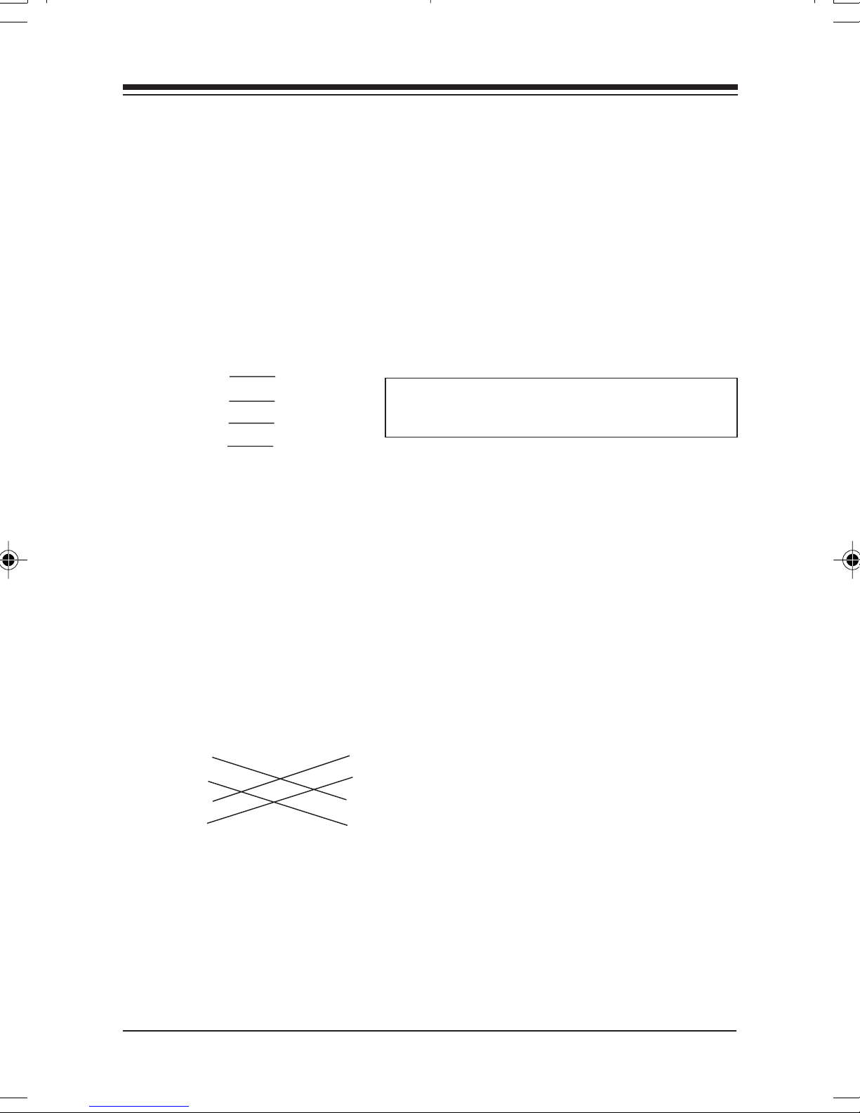
When connecting two identical twisted-pair ports (that is, ports
that either BOTH support or NOT support the crossover
function), a crossover must be implemented in the wiring (see
3.5).
CabCab
ling Characteristicsling Characteristics
Cab
ling Characteristics
CabCab
ling Characteristicsling Characteristics
Page 20
2020
20
2020
3.4 Straight-Thr3.4 Straight-Thr
3.4 Straight-Thr
3.4 Straight-Thr3.4 Straight-Thr
If the twisted pair link segment is to connect two devices and
only one of the devices features an internal crossover, the two
pairs of wires must be straight-through:
STRAIGHTSTRAIGHT
STRAIGHT
STRAIGHTSTRAIGHT
Device 1 Device 2
1 (Rx+) 1 (Tx+)
2 (Rx-) 2 (Tx-)
3 (Tx+) 3 (Rx+)
6 (Tx-) 6 (Rx-)
3.5 Cr3.5 Cr
3.5 Cr
3.5 Cr3.5 Cr
-THROUGH RJ-45 PIN ASSIGNMENTS-THROUGH RJ-45 PIN ASSIGNMENTS
-THROUGH RJ-45 PIN ASSIGNMENTS
-THROUGH RJ-45 PIN ASSIGNMENTS-THROUGH RJ-45 PIN ASSIGNMENTS
ossoosso
osso
ossoosso
vv
v
vv
er er
er
er er
ough ough
ough
ough ough
WW
irir
inging
W
ir
ing
WW
irir
inging
WW
irir
inging
W
ir
ing
WW
irir
inging
The assignments will vary if both areThe assignments will vary if both are
The assignments will vary if both are
The assignments will vary if both areThe assignments will vary if both are
“X”, or both are NOT “X”.“X”, or both are NOT “X”.
“X”, or both are NOT “X”.
“X”, or both are NOT “X”.“X”, or both are NOT “X”.
If you are connecting two devices directly that do not
implement internal crossover, then the crossover must be
implemented in the wiring.
CROSSOVER RJ-45 PIN ASSIGNMENTSCROSSOVER RJ-45 PIN ASSIGNMENTS
CROSSOVER RJ-45 PIN ASSIGNMENTS
CROSSOVER RJ-45 PIN ASSIGNMENTSCROSSOVER RJ-45 PIN ASSIGNMENTS
Device 1 Device 2
1 (+) 1 (+)
2 (-) 2 (-)
3 (+) 3 (+)
6 (-) 6 (-)
NOTE ON SIGNAL POLARITYNOTE ON SIGNAL POLARITY
NOTE ON SIGNAL POLARITY
NOTE ON SIGNAL POLARITYNOTE ON SIGNAL POLARITY
If a receive data pair has the “+” and “-” signals unintentionally
reversed, the BOCA NET-8 automatically detects and adjusts
this reversal so the data path will function properly.
BOCA NETBOCA NET
BOCA NET
BOCA NETBOCA NET
-8 Ethernet Kit-8 Ethernet Kit
-8 Ethernet Kit
-8 Ethernet Kit-8 Ethernet Kit
Page 21

PP
P
PP
arar
ar
arar
t III: t III:
t III:
t III: t III:
The 10Base-T EtherThe 10Base-T Ether
The 10Base-T Ether
The 10Base-T EtherThe 10Base-T Ether
net Netwnet Netw
net Netw
net Netwnet Netw
oror
k Cark Car
or
k Car
oror
k Cark Car
2121
21
2121
dd
d
dd
Section One: InstallaSection One: Installa
Section One: Installa
Section One: InstallaSection One: Installa
The 10Base-T Ethernet Network Card is compatible with
network hardware which complies with IEEE Ethernet 802.3
standards. The card offers a twisted-pair connector, plus a BNC
connector. The network card is compatible with existing
NE2000 drivers shipped with Novell and other operating
systems. In addition, drivers are also provided for full-duplex
operation when network switches are used. Throughput may
then reach as high as 20Mb/s.
PNP OR JUMPERLESS MODEPNP OR JUMPERLESS MODE
PNP OR JUMPERLESS MODE
PNP OR JUMPERLESS MODEPNP OR JUMPERLESS MODE
This selects the operating mode of the 10Base-T Network Card:
PNP (Plug and Play) or Jumperless (configured by
BENCFG.EXE).
tiontion
tion
tiontion
If either your BIOS is Plug and Play If either your BIOS is Plug and Play
1.
If either your BIOS is Plug and Play
If either your BIOS is Plug and Play If either your BIOS is Plug and Play
9595
95, do not install the
9595
Utility. Leave the card in the default Plug and Play mode.
NOTE:NOTE:
NOTE:
NOTE:NOTE:
Windows 95, you will need to know the system resources
assigned to the card. Run a utility such as Isolate to provide
this information.
If you do NOT have WIf you do NOT have W
2.
If you do NOT have W
If you do NOT have WIf you do NOT have W
Plug and PlayPlug and Play
Plug and Play, then you must install the
Plug and PlayPlug and Play
CardCard
Card Configuration Utility (see
CardCard
BENCFG and set the mode to “jumperless”. Press
changes made in BENCFG.
If you have a Plug and Play systemIf you have a Plug and Play system
If you have a Plug and Play system, but do not have
If you have a Plug and Play systemIf you have a Plug and Play system
10Base-T Network Card10Base-T Network Card
10Base-T Network Card Configuration
10Base-T Network Card10Base-T Network Card
indows 95, and your BIOS is NOTindows 95, and your BIOS is NOT
indows 95, and your BIOS is NOT
indows 95, and your BIOS is NOTindows 95, and your BIOS is NOT
Part III, Section Two
, or you have W, or you have W
, or you have W
, or you have W, or you have W
10Base-T Network10Base-T Network
10Base-T Network
10Base-T Network10Base-T Network
). Run
F10F10
F10 to save
F10F10
InstallationInstallation
Installation
InstallationInstallation
indowsindows
indows
indowsindows
Part III: The 10Base-T
Network Card
Page 22

2222
22
2222
1.1 Inser1.1 Inser
1.1 Inser
1.1 Inser1.1 Inser
RemoRemo
Remo
RemoRemo
These instructions assume an IBM-style or compatible machine.
1. Power-down your system and remove the power cord.
2. Use a screwdriver to remove the screws which hold the cover
in place. Obviously, locations and types of screws as well as
type of case cover will vary based on your particular system.
Refer to your computer system documentation for assistance.
3. Carefully remove the
cover from the computer.
Be careful not to let the
cover catch on internal
ting the ting the
ting the
ting the ting the
ving the System Coving the System Co
ving the System Co
ving the System Coving the System Co
AdaAda
Ada
AdaAda
pterpter
pter
pterpter
vv
v
vv
erer
er
erer
cables to disk drives,
controllers, or the power
supply.
InserInser
Inser
InserInser
4. Select an empty 16-bit slot and remove the screw and metal
5. Insert the adapter in the slot you have selected so that the
ting the Netwting the Netw
ting the Netw
ting the Netwting the Netw
plate that covers the external access to the slot you have
selected.
edge connectors on the bottom of the board mate with the
slot on the motherboard. Press down firmly on the
secure it with the screw you removed in step 4.
oror
k Cark Car
or
k Car
oror
k Cark Car
dd
d
dd
board and
BOCA NETBOCA NET
BOCA NET
BOCA NETBOCA NET
-8 Ethernet Kit-8 Ethernet Kit
-8 Ethernet Kit
-8 Ethernet Kit-8 Ethernet Kit
Page 23

2323
23
2323
Replacing the System CoReplacing the System Co
Replacing the System Co
Replacing the System CoReplacing the System Co
6. Slide the cover back over the chassis, again exercising care
not to let it catch on any cabling. Once the cover is back in
place, replace all the screws you removed in step 2.
Connecting CaConnecting Ca
Connecting Ca
Connecting CaConnecting Ca
7.
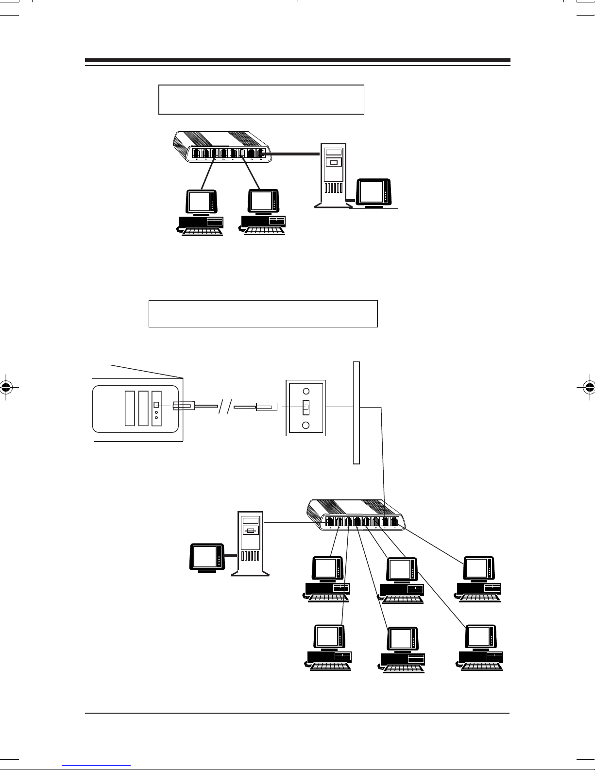
Connect one end of the Belkin 10Base-T cable to the RJ-45
connector on the board. Attach the remaining end to a
network outlet, hub, or concentrator as shown in the sample
configurations on the following page.
8. Re-attach all other external cables and power cords to their
original position. Installation of the hardware is now
complete. Go to section
blesbles
bles
blesbles
vv
erer
v
er
vv
erer
1.2 Adapter Configuration
.
InstallationInstallation
Installation
InstallationInstallation
Page 24
2424
24
2424
Small Office Configuration
Hub
Network
Server
Workstations (one
can also function as
server)
Multiworkstation Configuration
RJ-45
Connector
RJ-45 Belkin
Cable
Network
Server
Wall
Jack
Punch-down
Block
Hub
BOCA NETBOCA NET
BOCA NET
BOCA NETBOCA NET
-8 Ethernet Kit-8 Ethernet Kit
-8 Ethernet Kit
-8 Ethernet Kit-8 Ethernet Kit
Page 25

.
1.2 1.2
1.2
1.2 1.2
AdaAda
Ada
AdaAda
pter Confpter Conf
pter Conf
pter Confpter Conf
iguraigura
igura
iguraigura
tiontion
tion
tiontion
2525
25
2525
Loading a Single BoarLoading a Single Boar
Loading a Single Boar
Loading a Single BoarLoading a Single Boar
The 10Base-T Network Card is a software-configurable
Ethernet adapter. In order to change parameters, run the
configuration utility,
options:
I/O Base Address, Interrupt NumberI/O Base Address, Interrupt Number
I/O Base Address, Interrupt Number
I/O Base Address, Interrupt NumberI/O Base Address, Interrupt Number
Boot ROM Address.Boot ROM Address.
Boot ROM Address.
Boot ROM Address.Boot ROM Address.
Loading Multiple BoarLoading Multiple Boar
Loading Multiple Boar
Loading Multiple BoarLoading Multiple Boar
To load more than one 10Base-T Network Card in your
machine, you must configure each one separately. Configure
each board to a different interrupt and I/O base address. Insert
BENCFG.EXEBENCFG.EXE
BENCFG.EXE, to specify the following
BENCFG.EXEBENCFG.EXE
dd
d
dd
dsds
ds
dsds
, Run Diagnostics, and, Run Diagnostics, and
, Run Diagnostics, and
, Run Diagnostics, and, Run Diagnostics, and
one card and run BENCFG.EXE. When all cards have been
correctly configured, power down and re-insert all adapters.
The network driver must be loaded again for each new adapter
board installed in the system. For example, to load three
boards in a NetWare server environment, the following must
be entered.
For first adapter board: LOAD NE2000.LAN int=X1 Port=Y1
For second adapter board: LOAD NE2000.LAN int=X2 Port=Y2
For third adapter board:LOAD NE2000.LAN int=X3 Port=Y3
InstallationInstallation
Installation
InstallationInstallation
Page 26

2626
26
2626
Section Section
Section
Section Section
2.1 Dr2.1 Dr
2.1 Dr
2.1 Dr2.1 Dr
The 10Base-T Network Card is NE2000 and NE2000+
compatible. High-speed (full-duplex) drivers support the
following operating systems:
• Windows 95 (see p. 33 for Windows 95 driver installation)
• Novell Server 3.x and 4.x
• Novell ODI Workstation
• Windows for Workgroups 3.11
• Windows NT 3.51
• Packet Drivers
iv
TT
ww
o: Softwo: Softw
T
w
o: Softw
TT
ww
o: Softwo: Softw
iviv
er Supporer Suppor
er Suppor
iviv
er Supporer Suppor
arar
e Confe Conf
ar
e Conf
arar
e Confe Conf
tt
t
tt
iguraigura
igura
iguraigura
tiontion
tion
tiontion
2.2 Installa2.2 Installa
2.2 Installa
2.2 Installa2.2 Installa
Installation of the drivers and utilities is only necessary if either
of the following two conditions are true:
1. You are operating in a non Plug and Play environment. You
should then install the configuration utility BENCFG.EXE.
2. You want to install high-speed drivers for Novell Client ODI,
Novell Server drivers, or packet drivers.
NOTE: For operating systems such as Windows 95, Windows for
Work groups 3.11, and Windows NT, drivers are installed via a facility
in the operating system. You will need to follow the instructions in
this manual, as well as those supplied in your network operating
system documentation.
tion Notestion Notes
tion Notes
tion Notestion Notes
BOCA NETBOCA NET
BOCA NET
BOCA NETBOCA NET
-8 Ethernet Kit-8 Ethernet Kit
-8 Ethernet Kit
-8 Ethernet Kit-8 Ethernet Kit
Page 27
2727
27
2727
High-speed drivers for the 10Base-T Network Card for these
operating systems are provided in the following subdirectories
on the driver diskette as listed below.
Windows 95 \WIN95 (see Part III; section 2.4)
Windows NT \WINNT
Windows for Workgroups \WFW311
To start installation, type
the following introductory screen is displayed.
sure you have exited Wsure you have exited W
sure you have exited W
sure you have exited Wsure you have exited W
installation.installation.
installation.
installation.installation.
A:\INSTA:\INST
A:\INST
A:\INSTA:\INST
indows completely before starting theindows completely before starting the
indows completely before starting the
indows completely before starting theindows completely before starting the
ALLALL
ALL (or
ALLALL
B:\INSTB:\INST
B:\INST
B:\INSTB:\INST
ALLALL
ALL) and
ALLALL
NOTE: MakeNOTE: Make
NOTE: Make
NOTE: MakeNOTE: Make
This program installs the 10Base-T Network Card configuration
utility and drivers on your computer. Press the escape key
[ESC] at any time to abort the installation. Each question has a
default answer. If the default is correct, press ENTER in
response. Otherwise, type the correct answer and press ENTER.
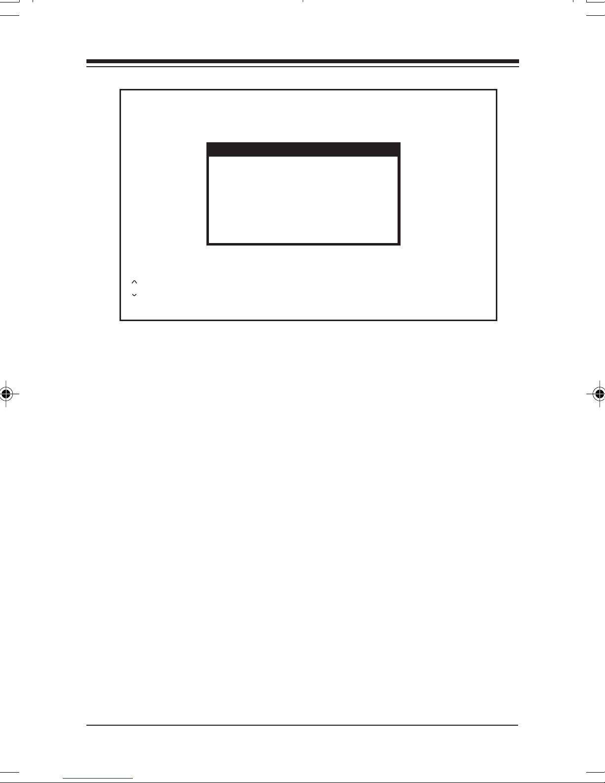
If you make a mistake, press the BACKSPACE key and retype
the answer. The Installation Option screen then appears:
InstallationInstallation
Installation
InstallationInstallation
Page 28
2828
28
2828
Select the file to install:
BOCALANcard Configuration Utilities
DOS ODI Client Drivers NO
Novell Server 3.11 Drivers NO
Novell Server 3.12 Drivers NO
Novell Server 4.x Drivers NO
Packet Drivers NO
Windows 95 NO
Windows NT 3.51 NO
Windows for Workgroups 3.11 NO
| - scroll up PgUp - scroll page up Enter - install selections
| - scroll down PgDn - scroll page down Space bar - toggle Yes/No
Y - all YES N - all NO Esc - Exit Install
NO
The choices are as follows:
• 10Base-T network Card Configuration Utilities
• DOS ODI Client Drivers
• Novell Server 3.11 Drivers
• Novell Server 3.12 Drivers
• Novell Server 4.x Drivers
• Packet Drivers
• Windows 95
• Windows NT 3.51
• Windows for Workgroups 3.11
2.3 Conf2.3 Conf
2.3 Conf
2.3 Conf2.3 Conf
iguraigura
igura
iguraigura
tiontion
tion
tiontion
Configuration is “automatic” when running a Plug and Play
system. Otherwise, the 10Base-T Network Card is configured
with the BENCFG.EXE program, which is installed when you
select “10Base-T Network Card Configuration Utilities” from
the installation menu. The card can operate in one of two
modes:
BOCA NETBOCA NET
BOCA NET
BOCA NETBOCA NET
-8 Ethernet Kit-8 Ethernet Kit
-8 Ethernet Kit
-8 Ethernet Kit-8 Ethernet Kit
Page 29
2929
29
2929
1. Non Plug and Play Systems:1. Non Plug and Play Systems:
1. Non Plug and Play Systems:
1. Non Plug and Play Systems:1. Non Plug and Play Systems:
• Software-configurable by the BENCFG.EXE program
(jumperless), or
2. Plug and Play Systems:2. Plug and Play Systems:
2. Plug and Play Systems:
2. Plug and Play Systems:2. Plug and Play Systems:
• Plug and Play Mode (factory default). If you have Plug and
Play, running or installing BENCFG.EXE is NOT necessary.
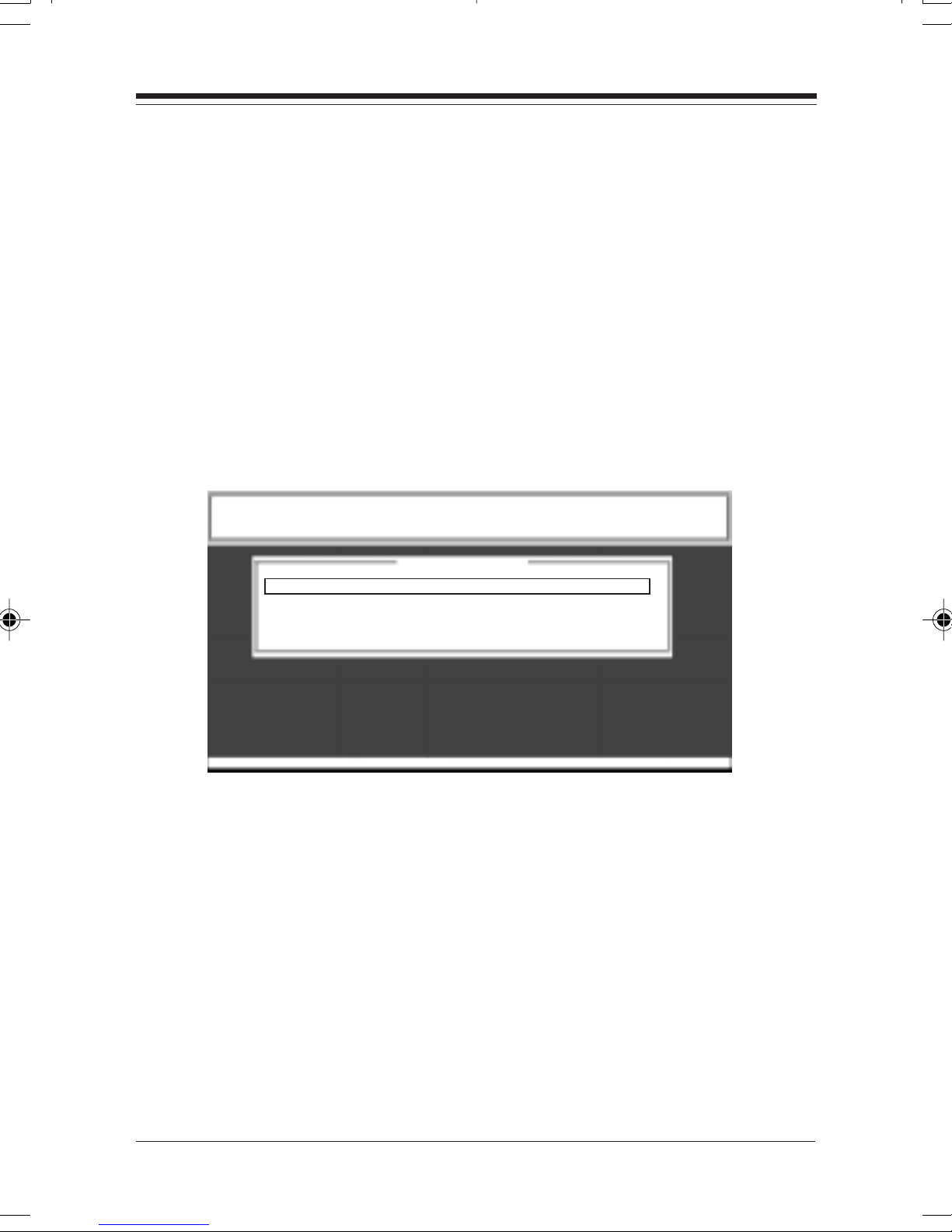
When you run BENCFG.EXE, the following main selection
screen is displayed:
BOCALANCard Configuration Utility
For BEN400IT and BEN400I2
Boca Research, Inc.
Configuration Menu
I/O Base Address - 0x300
Interrupt Output Line - IRQ 5
Boot ROM Base Address - No Boot ROM
PNP or Jumperless Mode - Plug and Play
Ethernet Address - 00C06D10ABE2
F1 Help | | Select F5 Diagnose F10 Save Esc Quit
The options are summarized as follows:
I/O Base Address:I/O Base Address:
I/O Base Address: Changes the board’s I/O address when in
I/O Base Address:I/O Base Address:
“jumperless” mode.
Interrupt Output Line:Interrupt Output Line:
Interrupt Output Line: Changes the board’s IRQ when in
Interrupt Output Line:Interrupt Output Line:
“jumperless” mode.
Boot ROM Base Address:Boot ROM Base Address:
Boot ROM Base Address: Specifies Boot ROM options or no
Boot ROM Base Address:Boot ROM Base Address:
Boot ROM.
InstallationInstallation
Installation
InstallationInstallation
Page 30
3030
30
3030
PNP or Jumperless Mode:PNP or Jumperless Mode:
PNP or Jumperless Mode: Specifies Plug and Play or
PNP or Jumperless Mode:PNP or Jumperless Mode:
jumperless mode.
Ethernet Address:Ethernet Address:
Ethernet Address: Displays the IEEE Ethernet address assigned
Ethernet Address:Ethernet Address:
to the board (this is never user-configurable).
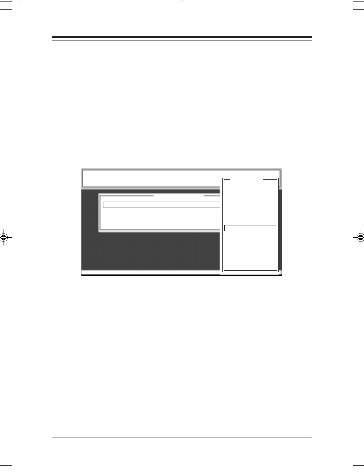
I/O Base I/O Base
I/O Base
I/O Base I/O Base
AddrAddr
Addr
AddrAddr
F1 Help | | Select F5 Diagnose F10 Save Esc Quit
essess
ess
essess
BOCALANcard Configuration Utility
For BEN400IT and BEN400I2
Boca Research, Inc.
Configuration Menu
I/O Base Address - 0x300
Interrupt Output Line - IRQ 5
Boot ROM Base Address - No Boot ROM
PNP or Jumperless Mode - Jumperless
Ethernet Address - 00C06D10ABE2
I/O Base
200H -- 21FH
220H -- 23FH
240H -- 25FH
260H -- 27FH
280H -- 29FH
2A0H -- 2BFH
2C0H -- 2DFH
2E0H -- 2FFH
300H -- 31FH
320H -- 33FH
340H -- 35FH
360H -- 37FH
380H -- 39FH
3A0H -- 3BFH
3C0H -- 3DFH
3E0H -- 3FFH
The 10Base-T Network Card can operate in a range from 0200h
to 03E0h, requiring an address window of 1Fh. If the board is in
Plug and Play mode, you will not be able to change the I/O
address because the Plug and Play configuration is responsible
for the configuration of Plug and Play boards. Also, if the board
is in non Plug and Play (or “jumperless” mode), the
BENCFG.EXE program determines which I/O addresses are in
use by other devices and “grays” out (disables) these choices.
BOCA NETBOCA NET
BOCA NET
BOCA NETBOCA NET
-8 Ethernet Kit-8 Ethernet Kit
-8 Ethernet Kit
-8 Ethernet Kit-8 Ethernet Kit
Page 31
IRQIRQ
IRQ
IRQIRQ
BOCALANcard Configuration Utility
For BEN400IT and BEN400I2
Boca Research, Inc.
Configuration Menu
I/O Base Address - 0x300
Interrupt Output Line - IRQ 5
Boot ROM Base Address - No Boot ROM
PNP or Jumperless Mode - Jumperless
Ethernet Address - 00C06D10ABE2
F1 Help | | Select F5 Diagnose F10 Save Esc Quit
IRQ Number
IRQ Level 3
IRQ Level 4
IRQ Level 5
IRQ Level 9(2)
IRQ Level 10
IRQ Level 11
IRQ Level 12
IRQ Level 15
3131
31
3131
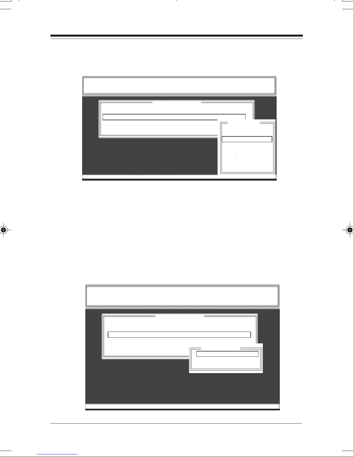
The 10Base-T Network Card can operate with the following
IRQ settings: 3, 4, 5, 9(2), 10, 11, 12, or 15. Note that most
secondary IDE hard-disk controllers operate on IRQ15, so if the
system is not a “diskless workstation”, IRQ15 should be
avoided.
BOOBOO
BOO
BOOBOO
T RT R
T R
T RT R
OM BOM B
OM B
OM BOM B
ASE ASE
ASE
ASE ASE
ADDRESSADDRESS
ADDRESS
ADDRESSADDRESS
BOCALANcard Configuration Utility
For BEN400IT and BEN400I2
Boca Research, Inc.
Configuration Menu
I/O Base Address - 0x300
Interrupt Output Line - IRQ 5
Boot ROM Base Address - No Boot ROM
PNP or Jumperless Mode - Jumperless
Ethernet Address - 00C06D10ABE2
ROM Address
C8000H -- CBFFFH
CC000H -- CFFFFH
D0000H -- D3FFFH
F1 Help | | Select F5 Diagnose F10 Save Esc Quit
InstallationInstallation
Installation
InstallationInstallation
Page 32

3232
32
3232
10Base-T Network Card10Base-T Network Card
The
10Base-T Network Card is compatible with an NE2000-
10Base-T Network Card10Base-T Network Card
type Boot ROM. Refer to the documentation provided with
your boot ROM for configuration instructions. Do NOT enable
this option unless there is a boot ROM present. The default
setting is NO BOOT ROM.
Notes on Using the 10Base-T NetwNotes on Using the 10Base-T Netw
Notes on Using the 10Base-T Netw
Notes on Using the 10Base-T NetwNotes on Using the 10Base-T Netw
Play Mode without Using a Plug and Play OperaPlay Mode without Using a Plug and Play Opera
Play Mode without Using a Plug and Play Opera
Play Mode without Using a Plug and Play OperaPlay Mode without Using a Plug and Play Opera
SystemSystem
System
SystemSystem
It is possible to use the 10Base-T Network Card in Plug and
Play mode without using a Plug and Play operating system.
Your operating system vendor may provide software utilities to
do so. For example, Intel Corp. provides the “ISA Plug and Play
Kit” for MS-DOS type computers. These utilities configure the
10Base-T Network Card10Base-T Network Card
10Base-T Network Card when in Plug and Play mode. The
10Base-T Network Card10Base-T Network Card
BENCFG program can report how the utility configured the
card (I/O Address, IRQ) so that you can set up your operating
system accordingly.
oror
k Cark Car
or
k Car
oror
k Cark Car
d in Plug andd in Plug and
d in Plug and
d in Plug andd in Plug and
tingting
ting
tingting
2.4 2.4
WW
2.4
2.4 2.4
Please check the version of WPlease check the version of W
Please check the version of W
Please check the version of WPlease check the version of W
click on the “My Computer” icon on the desktop and selectclick on the “My Computer” icon on the desktop and select
click on the “My Computer” icon on the desktop and select
click on the “My Computer” icon on the desktop and selectclick on the “My Computer” icon on the desktop and select
“Properties”. Under “System”, if your version reads “Properties”. Under “System”, if your version reads
“Properties”. Under “System”, if your version reads
“Properties”. Under “System”, if your version reads “Properties”. Under “System”, if your version reads
you have OEM Service Release 2 of Wyou have OEM Service Release 2 of W
you have OEM Service Release 2 of W
you have OEM Service Release 2 of Wyou have OEM Service Release 2 of W
continue with page 33continue with page 33
continue with page 33
continue with page 33continue with page 33
earlier release of Wearlier release of W
earlier release of W
earlier release of Wearlier release of W
of Wof W
of W
of Wof W
BOCA NETBOCA NET
BOCA NET
BOCA NETBOCA NET
indoindo
W
indo
WW
indoindo
indows 95” on page 34.indows 95” on page 34.
indows 95” on page 34.
indows 95” on page 34.indows 95” on page 34.
ws 95 Drws 95 Dr
ws 95 Dr
ws 95 Drws 95 Dr
-8 Ethernet Kit-8 Ethernet Kit
-8 Ethernet Kit
-8 Ethernet Kit-8 Ethernet Kit
iviv
er Installaer Installa
iv
er Installa
iviv
er Installaer Installa
indows 95 that you are using. Rightindows 95 that you are using. Right
indows 95 that you are using. Right
indows 95 that you are using. Rightindows 95 that you are using. Right
. If your version is not 4.00.950 B, you have an. If your version is not 4.00.950 B, you have an
. If your version is not 4.00.950 B, you have an
. If your version is not 4.00.950 B, you have an. If your version is not 4.00.950 B, you have an
indows 95indows 95
indows 95.
indows 95indows 95
In that case, go to “Earlier VIn that case, go to “Earlier V
In that case, go to “Earlier V
In that case, go to “Earlier VIn that case, go to “Earlier V
tiontion
tion
tiontion
4.00.950 B4.00.950 B
4.00.950 B
4.00.950 B4.00.950 B
indows 95. In this case,indows 95. In this case,
indows 95. In this case,
indows 95. In this case,indows 95. In this case,
ersionsersions
ersions
ersionsersions
, then, then
, then
, then, then
Page 33

3333
33
3333
For For
WW
For
For For
1. With the 10BaseT/2 Network Card installed in your system, start
indoindo
W
indo
WW
indoindo
Windows 95 as you normally would.
ws 95 ws 95
ws 95
ws 95 ws 95
VV
erer
sion 4.00.950 B:sion 4.00.950 B:
V
er
sion 4.00.950 B:
VV
erer
sion 4.00.950 B:sion 4.00.950 B:
2. When Windows 95 detects new hardware, it starts the
Device Driver WDevice Driver W
Device Driver W
Device Driver WDevice Driver W
3. Insert the “Boca BEN400 Driver Disk” and click
TT
o install Full-Duplex drivers under Wo install Full-Duplex drivers under W
T
o install Full-Duplex drivers under W
TT
o install Full-Duplex drivers under Wo install Full-Duplex drivers under W
otherwise, complete driver installation with step 4:otherwise, complete driver installation with step 4:
otherwise, complete driver installation with step 4:
otherwise, complete driver installation with step 4:otherwise, complete driver installation with step 4:
CAUTION: Using this driver with a half-duplex hub can result in diminishedCAUTION: Using this driver with a half-duplex hub can result in diminished
CAUTION: Using this driver with a half-duplex hub can result in diminished
CAUTION: Using this driver with a half-duplex hub can result in diminishedCAUTION: Using this driver with a half-duplex hub can result in diminished
performance.performance.
performance.
performance.performance.
• Click
• After Windows 95 finishes its search, click on
• Enter the path
• •
• Next, the “
• •
the following selections under “Property”:
EARLYTRANSMIT (enables early transmit; allows processing of data while still
receiving data from the network, increasing overall throughput).
NextNext
Next. Windows 95 searches for updated drivers.
NextNext
Network CardNetwork Card
Network Card Properties” screen is displayed. Note
Network CardNetwork Card
izard”izard”
izard”.
izard”izard”
indows 95, continue belowindows 95, continue below
indows 95, continue below
indows 95, continue belowindows 95, continue below
A:\WIN95\FLDPXA:\WIN95\FLDPX
A:\WIN95\FLDPX and click
A:\WIN95\FLDPXA:\WIN95\FLDPX
Next.Next.
Next.
Next.Next.
Other LocationsOther Locations
Other Locations.
Other LocationsOther Locations
OKOK
OK.
OKOK
“Update“Update
“Update
“Update“Update
,,
,
,,
EARLYRECEIVE (enables early receive; allows processing of data while
sending data to the network, increasing overall throughput).
FULL DUPLEX (enables full duplex; allows the Network Card to transmit and
receive data at the same time without causing a collision. This increases and width
from 10Mbs to 20Mbs. Note that the use of a full duplex Ethernet switch is
required.)
“V“V
Under
(highlight each one by one).
• Select
prompted for your original Windows 95 CD or diskettes from
which files will be copied. Installation of the Windows 95 FullDuplex driver is complete
4. After Windows 95 finishes searching for updated drivers, click on
the
Windows 95 users.
alue”alue”
“V
alue”, select
“V“V
alue”alue”
OKOK
OK. Files are then copied to your system. You may be
OKOK
FinishFinish
Finish button. Congratulations! Setup is complete for
FinishFinish
EnableEnable
Enable for all three of these properties
EnableEnable
.
InstallationInstallation
Installation
InstallationInstallation
Page 34

3434
34
3434
For EarFor Ear
For Ear
For EarFor Ear
1. With the 10BaseT/2 Network Card installed in your system, start
Windows 95 as you normally would.
2. When Windows 95 detects new hardware, it displays the
Hardware FoundHardware Found
Hardware Found dialog box. Here, you are asked what driver files
Hardware FoundHardware Found
are associated with the new hardware.
3. From the choices given, select
hardware manufacturerhardware manufacturer
hardware manufacturer.
hardware manufacturerhardware manufacturer
4. Windows 95 then displays the
you are asked for the location of the driver files. Insert the “Boca
BEN400 Driver Disk” in your floppy drive.
TT
o install Full-Duplex drivers under Wo install Full-Duplex drivers under W
T
o install Full-Duplex drivers under W
TT
o install Full-Duplex drivers under Wo install Full-Duplex drivers under W
otherwise, complete driver installation with step 5:otherwise, complete driver installation with step 5:
otherwise, complete driver installation with step 5:
otherwise, complete driver installation with step 5:otherwise, complete driver installation with step 5:
CAUTION: Using this driver with a half-duplex hub can result in diminishedCAUTION: Using this driver with a half-duplex hub can result in diminished
CAUTION: Using this driver with a half-duplex hub can result in diminished
CAUTION: Using this driver with a half-duplex hub can result in diminishedCAUTION: Using this driver with a half-duplex hub can result in diminished
performance.performance.
performance.
performance.performance.
• Enter the path
lier lier
lier
lier lier
VV
erer
sions of sions of
V
er
sions of
VV
erer
sions of sions of
A:\WIN95\FLDPXA:\WIN95\FLDPX
A:\WIN95\FLDPX and click
A:\WIN95\FLDPXA:\WIN95\FLDPX
WW
W
WW
indoindo
indo
indoindo
ws 95:ws 95:
ws 95:
ws 95:ws 95:
Driver from disk provided byDriver from disk provided by
Driver from disk provided by
Driver from disk provided byDriver from disk provided by
“Install from Disk”“Install from Disk”
“Install from Disk” dialog box. Here,
“Install from Disk”“Install from Disk”
NewNew
New
NewNew
indows 95, continue belowindows 95, continue below
indows 95, continue below
indows 95, continue belowindows 95, continue below
OKOK
OK.
OKOK
,,
,
,,
• •
• Next, the
• •
following selections under
EARLYTRANSMIT (enables early transmit; allows processing of data while still
receiving data from the network, increasing overall throughput).
EARLYRECEIVE (enables early receive; allows processing of data while sending data
to the network, increasing overall throughput).
FULL DUPLEX (enables full duplex; allows the Network Card to transmit and receiv e
data at the same time without causing a collision. This increases and width from 10Mbs
to 20Mbs. Note that the use of a full duplex Ethernet switch is required.)
Under
each one by one).
• Select
prompted for your original Windows 95 CD or diskettes from which
files will be copied. Installation of the Windows 95 Full-Duplex
driver is complete.
5. Enter the path A:\WIN95 (or B:\WIN95) and click
driver is copied, may be prompted for your original Windows 95 CD
or diskettes from which files will be copied. Congratulations! Setup
is complete for Windows 95.
“Network Card Properties”“Network Card Properties”
“Network Card Properties” screen is displayed. Note the
“Network Card Properties”“Network Card Properties”
“Property”“Property”
“Property”:
“Property”“Property”
“V“V
alue”alue”
“V
alue”, select
“V“V
alue”alue”
OKOK
OK. Files are then copied to your system. You may be
OKOK
EnableEnable
Enable for all three of these properties (highlight
EnableEnable
OKOK
OK. After the
OKOK
BOCA NETBOCA NET
BOCA NET
BOCA NETBOCA NET
-8 Ethernet Kit-8 Ethernet Kit
-8 Ethernet Kit
-8 Ethernet Kit-8 Ethernet Kit
Page 35
PP
P
PP
arar
ar
arar
t IVt IV
t IV
t IVt IV
: :
TT
rr
oubleshootingoubleshooting
:
T
r
oubleshooting
: :
TT
rr
oubleshootingoubleshooting
3535
35
3535
Part IV: Troubleshooting
1.1 BOC1.1 BOC
1.1 BOC
1.1 BOC1.1 BOC
StaSta
tus/Diagnostic LEDstus/Diagnostic LEDs
Sta
tus/Diagnostic LEDs
StaSta
tus/Diagnostic LEDstus/Diagnostic LEDs
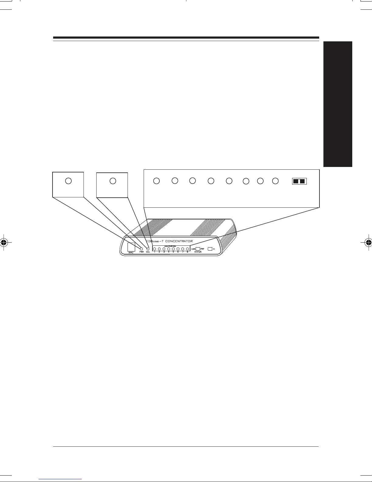
The BOCA NET-8 features a total of ten front panel LEDs to aid
in testing the installation and the diagnosing of problems. There
are eight LINK/PARTITION LEDs, one Power LED, and one
Collision LED.
PWR
A NETA NET
A NET
A NETA NET
Col
-8 Hub-8 Hub
-8 Hub
-8 Hub-8 Hub
1
4
36
2
L I N K / P A R T I T I O N
5
7
8
LNK
Status
PRT
Ports one through eight feature an associated Link/Partition
LED. A switch is used to toggle between the
PP
ARAR
P
PP
When set to
a given port IF a device is physically attached and functioning
normally. If the LED is
with the corresponding device.
When set to
for a given port IF a device is physically attached and
functioning normally. If the LED is
has been isolated from the network because of a
(concentrator receiving data from two or more nodes at the
same time).
TITION TITION
AR
TITION display status.
ARAR
TITION TITION
LINK LINK
LINK, the status LED will be
LINK LINK
PP
ARAR
P
PP
TITIONTITION
AR
TITION, the LED will be
ARAR
TITIONTITION
OFFOFF
OFF or
OFFOFF
FLASHINGFLASHING
FLASHING, there is a problem
FLASHINGFLASHING
ONON
ON, the associated device
ONON
LINKLINK
LINK and
LINKLINK
ONON
ON continuously for
ONON
OFFOFF
OFF continuously
OFFOFF
COLLISIONCOLLISION
COLLISION
COLLISIONCOLLISION
TT
rr
ouboub
T
TT
leshootingleshooting
r
oub
leshooting
rr
ouboub
leshootingleshooting
Page 36

3636
36
3636
Each BOCA NET-8 concentrator also has:
• A GREEN power LED to indicate that the BOCA NET-8 has
power.
• One RED collision LED to signal a network collision. If this
light goes ON, toggle the LNK/PRT switch to PRT (for
PARTITION), to isolate which device is causing the collision.
LED functionality is summarized as follows:
LED COLOR # STATUS MEANING
POWER GREEN 1 ON
COLLISION RED 1 ON
PORT GREEN 8 ON
LINK
STATUS
(1-8)
PORT GREEN 8 OFF
PARTITION
STATUS
(1-8)
ON
BOCA NET-8 has power.
A network collision has
been detected. BOCA
NET-8 is receiving data
from two or more nodes
at the same time.
The port is receiving a
valid link test signal.
Associated device is
attached and functioning
normally.
Device has been isolated
because of COLLISION
BOCA NETBOCA NET
BOCA NET
BOCA NETBOCA NET
-8 Ethernet Kit-8 Ethernet Kit
-8 Ethernet Kit
-8 Ethernet Kit-8 Ethernet Kit
Page 37

3737
37
3737
InstallaInstalla
Installa
InstallaInstalla
1. POWER UP THE BOCA1. POWER UP THE BOCA
1. POWER UP THE BOCA
1. POWER UP THE BOCA1. POWER UP THE BOCA
The Power LED should be ON. If the ports are connected to
active devices, their LINK LEDs will remain on after power-on.
2. IF THE POWER LED IS NOT ON AND THE BOCA2. IF THE POWER LED IS NOT ON AND THE BOCA
2. IF THE POWER LED IS NOT ON AND THE BOCA
2. IF THE POWER LED IS NOT ON AND THE BOCA2. IF THE POWER LED IS NOT ON AND THE BOCA
SHOWS NO ACTIVITYSHOWS NO ACTIVITY
SHOWS NO ACTIVITY
SHOWS NO ACTIVITYSHOWS NO ACTIVITY
Check the connections between the concentrator, the power
cord, and the wall outlet.
Try another AC power adapter that you know works. If the
Power LED still fails to come ON, the BOCA NET-8 may be
tion tion
tion
tion tion
TT
estest
T
est
TT
estest
NET NET
NET
NET NET
-8 AND CHECK THE LEDs-8 AND CHECK THE LEDs
-8 AND CHECK THE LEDs
-8 AND CHECK THE LEDs-8 AND CHECK THE LEDs
NET NET
NET
NET NET
-8-8
-8
-8-8
faulty. Call Technical Support.
3. IF THE LINK LEDs DO NOT RESPOND3. IF THE LINK LEDs DO NOT RESPOND
3. IF THE LINK LEDs DO NOT RESPOND
3. IF THE LINK LEDs DO NOT RESPOND3. IF THE LINK LEDs DO NOT RESPOND
Check that the LNK/PRT switch is set to LNK.
Check the connections between each network device and the
concentrator port, including wiring. Make certain all devices
have power and are working normally.
TT
T
TT
rr
ouboub
leshootingleshooting
r
oub
leshooting
rr
ouboub
leshootingleshooting
Page 38

3838
38
3838
1.2 10Base-T Netw1.2 10Base-T Netw
1.2 10Base-T Netw
1.2 10Base-T Netw1.2 10Base-T Netw
If you encounter difficulties with your 10Base-T Network Card,
the problem may be a faulty installation or configuration
settings which conflict with other devices. Check the following:
• ST• ST
• ST
• ST• ST
GREEN:GREEN:
GREEN:
GREEN:GREEN:
RED:RED:
RED:
RED:RED:
Power on the system, connect the network cable, and observe
AA
TUS LEDsTUS LEDs
A
TUS LEDs. The 10Base-T Network Card has two LEDs
AA
TUS LEDsTUS LEDs
that are visible from the rear of the board. These status
indicators show whether or not the cable is connected along
with transmit/receive activity.
Link/Receive StatusLink/Receive Status
Link/Receive Status
Link/Receive StatusLink/Receive Status
TT
ransmit Statusransmit Status
T
ransmit Status
TT
ransmit Statusransmit Status
oror
k Cark Car
or
k Car
oror
k Cark Car
dd
d
dd
the LEDs. The green LED shows that it is connected with
another 10Base-T transceiver. If the green light is ON, then the
system is connected to the network. If the green light is
flickering, the system is connected to
the network. See charts explaining LED status on next page.
andand
and receiving data from
andand
BOCA NETBOCA NET
BOCA NET
BOCA NETBOCA NET
-8 Ethernet Kit-8 Ethernet Kit
-8 Ethernet Kit
-8 Ethernet Kit-8 Ethernet Kit
Page 39
3939
39
3939
Using RJ45 with connection type set to Auto (default) or
RJ-45
LIGHT CONDITION STATUS
GREEN ON LINK established
OFF No LINK established
Flickering Receiving data from
network
RED ON Network Card NOT
transmitting data to
network.
Flickering Network Card IS
transmitting data to network
Using BNC with connection type set to Auto (default)
LIGHT CONDITION STATUS
GREEN OFF Always off.
RED ON Network Card NOT
transmitting data to
network.
Flickering Network Card IS
transmitting data to network
TT
rr
ouboub
T
TT
leshootingleshooting
r
oub
leshooting
rr
ouboub
leshootingleshooting
Page 40
4040
40
4040
Using BNC with connection type set to BNC
LIGHT CONDITION STATUS
GREEN ON Network Card not
receiving data from
network
Flickering Network Card IS
receiving data from the
network.
RED ON Network Card NOT
transmitting data to
network.
Flickering Network Card IS
transmitting data to
network
• BOARD SETTINGS.• BOARD SETTINGS.
• BOARD SETTINGS. If you are using a Novell® network,
• BOARD SETTINGS.• BOARD SETTINGS.
make sure that the settings in the NET.CFG file are correct.
Also, when NE2000.COM is executed, NET.CFG must be in
the same directory as NE2000.COM.
If you are using another type of network (NDIS, etc.), read
the driver installation instructions again to be sure that I/O
address and IRQ settings are correct.
Review the installation again and check software setup.
BOCA NETBOCA NET
BOCA NET
BOCA NETBOCA NET
-8 Ethernet Kit-8 Ethernet Kit
-8 Ethernet Kit
-8 Ethernet Kit-8 Ethernet Kit
Page 41

4141
41
4141
Also make sure that any of the setting selections you have
made do not conflict with devices that are currently in your
system. You may want to vary the settings on your board to
see if it makes a difference. Remember to modify the
NET.CFG or your batch files as well.
• MAKE SURE THA• MAKE SURE THA
• MAKE SURE THA
• MAKE SURE THA• MAKE SURE THA
CONNECTED TO IS FUNCTIONING.CONNECTED TO IS FUNCTIONING.
CONNECTED TO IS FUNCTIONING.
CONNECTED TO IS FUNCTIONING.CONNECTED TO IS FUNCTIONING.
• REPLACE THE ADAPTER WITH ANOTHER KNOWN TO• REPLACE THE ADAPTER WITH ANOTHER KNOWN TO
• REPLACE THE ADAPTER WITH ANOTHER KNOWN TO
• REPLACE THE ADAPTER WITH ANOTHER KNOWN TO• REPLACE THE ADAPTER WITH ANOTHER KNOWN TO
FUNCTION AND TRFUNCTION AND TR
FUNCTION AND TR
FUNCTION AND TRFUNCTION AND TR
••
TRTR
•
••
• MAKE SURE YOU ARE USING DRIVERS MADE FOR• MAKE SURE YOU ARE USING DRIVERS MADE FOR
• MAKE SURE YOU ARE USING DRIVERS MADE FOR
• MAKE SURE YOU ARE USING DRIVERS MADE FOR• MAKE SURE YOU ARE USING DRIVERS MADE FOR
• REFER TO THE README FILE FOR A COMPREHENSIVE• REFER TO THE README FILE FOR A COMPREHENSIVE
• REFER TO THE README FILE FOR A COMPREHENSIVE
• REFER TO THE README FILE FOR A COMPREHENSIVE• REFER TO THE README FILE FOR A COMPREHENSIVE
Y THE ADAPTER IN AY THE ADAPTER IN A
TR
Y THE ADAPTER IN A
TRTR
Y THE ADAPTER IN AY THE ADAPTER IN A
NE2000 COMPNE2000 COMP
NE2000 COMP
NE2000 COMPNE2000 COMP
LIST OF POSSIBLE ERROR MESSAGES ANDLIST OF POSSIBLE ERROR MESSAGES AND
LIST OF POSSIBLE ERROR MESSAGES AND
LIST OF POSSIBLE ERROR MESSAGES ANDLIST OF POSSIBLE ERROR MESSAGES AND
SUGGESTED REMEDIES.SUGGESTED REMEDIES.
SUGGESTED REMEDIES.
SUGGESTED REMEDIES.SUGGESTED REMEDIES.
T THE NETWORK YOU ARET THE NETWORK YOU ARE
T THE NETWORK YOU ARE
T THE NETWORK YOU ARET THE NETWORK YOU ARE
Y TO LOGIN AGAIN.Y TO LOGIN AGAIN.
Y TO LOGIN AGAIN.
Y TO LOGIN AGAIN.Y TO LOGIN AGAIN.
DIFFERENT COMPUTER. DIFFERENT COMPUTER.
DIFFERENT COMPUTER.
DIFFERENT COMPUTER. DIFFERENT COMPUTER.
AA
TIBILITYTIBILITY
A
TIBILITY
AA
TIBILITYTIBILITY
..
.
..
If none of the above isolates and solves the problem, refer to
Appendix F: Servicing Your Boca Product.
TT
T
TT
rr
ouboub
leshootingleshooting
r
oub
leshooting
rr
ouboub
leshootingleshooting
Page 42

4242
42
4242
Appendix Appendix
Appendix
Appendix Appendix
BOCBOC
BOC
BOCBOC
Operating
Temperature: 20-50 Centigrade
Relative Humidity: 70%
(non-condensing)
Power: 9vac @ 750mA
Twisted-Pair Cable
Interface: Unshielded Twisted Pair
Crossover Ports: 7 preset/1 switch-selectable
A NETA NET
A NET
A NETA NET
A: SpecifA: Specif
A: Specif
A: SpecifA: Specif
-8 Hub-8 Hub
-8 Hub
-8 Hub-8 Hub
icaica
ica
icaica
tionstions
tions
tionstions
Connector: RJ-45
BOCA NETBOCA NET
BOCA NET
BOCA NETBOCA NET
-8 Ethernet Kit-8 Ethernet Kit
-8 Ethernet Kit
-8 Ethernet Kit-8 Ethernet Kit
Page 43

4343
43
4343
10Base-T Netw10Base-T Netw
10Base-T Netw
10Base-T Netw10Base-T Netw
• 10Base-T twisted pair transceiver with RJ-45 connector
• 10Base-T operating distance 100 meters (328') maximum hub
to node length
• Diagnostic LEDs: link/receive (GREEN LED) indicator and
transmit (RED LED) indicator
• Software-Selectable interrupts, memory address, and a base
I/O address.
oror
k Cark Car
or
k Car
oror
k Cark Car
dd
d
dd
Part V: Appendices
SpecificationsSpecifications
Specifications
SpecificationsSpecifications
Page 44
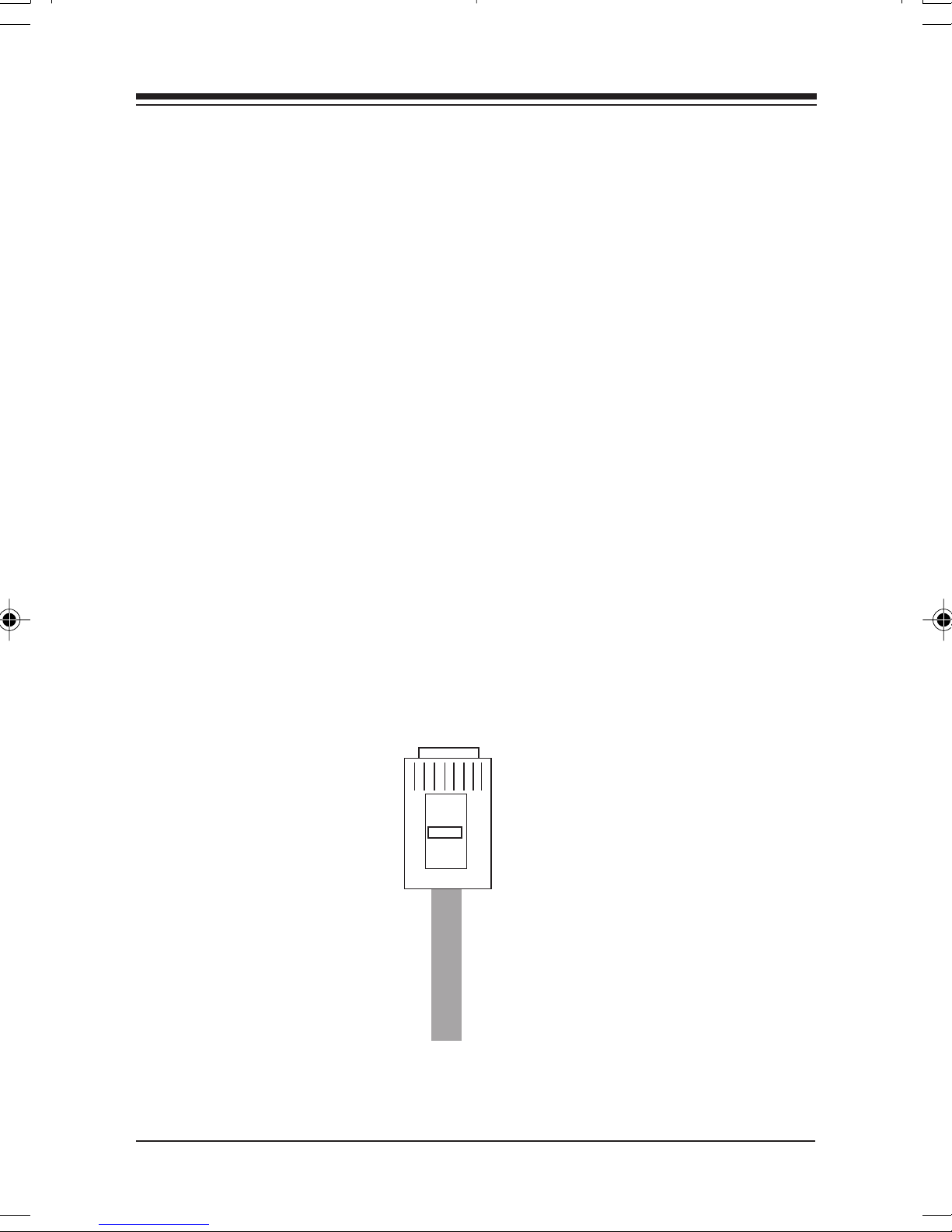
4444
44
4444
Appendix B: Pin-Out Appendix B: Pin-Out
Appendix B: Pin-Out
Appendix B: Pin-Out Appendix B: Pin-Out
Pin-out assignments for the 10Base-T connector are as follows:
8-pin8-pin
8-pin
8-pin8-pin
1 Tx+
2 Tx3 Rx+
4NC
5NC
6 Rx7NC
8NC
AssignmentsAssignments
Assignments
AssignmentsAssignments
Boca’s Ethernet products use a 8-pin 10Base-T connector.
8-pin RJ45
Connector
Pin 1
Bottom of
plug
Pin 8
BOCA NETBOCA NET
BOCA NET
BOCA NETBOCA NET
-8 Ethernet Kit-8 Ethernet Kit
-8 Ethernet Kit
-8 Ethernet Kit-8 Ethernet Kit
Page 45

4545
45
4545
Appendix C: NETAppendix C: NET
Appendix C: NET
Appendix C: NETAppendix C: NET
Included on the driver disk in the Novell® ODI sub-directory is
a file that establishes the base settings for your adapter. This file
is called NET.CFG, and is a text file that describes these
settings. If a configuration is different from the default settings
or if you are using multiple protocols, you need to modify this
NET.CFG file. This appendix explains how.
The NET.CFG file is a configuration file that contains section
headings and options for the ODI software.
You may also need to see the documentation specific to your
protocol for additional NET.CFG information. Use any DOS
text editor to modify the file.
.CFG Options f.CFG Options f
.CFG Options f
.CFG Options f.CFG Options f
or NetWor NetW
or NetW
or NetWor NetW
arar
ar
arar
e®e®
e®
e®e®
ConCon
Con
ConCon
Main section headings must be left-justified and are not case
sensitive. The heading must precede the options you want to
include in that section. Options are not case sensitive and must
be preceded by a tab or hard spaces.
Precede comments with a semicolon (;). End each line with a
hard return. Write all numbers in decimal notation except
where noted otherwise.
vv
entionsentions
v
entions
vv
entionsentions
NETNET
.CFG Options f.CFG Options f
NET
.CFG Options f
NETNET
.CFG Options f.CFG Options f
or NetWor NetW
or NetW
or NetWor NetW
areare
are
areare
Page 46
4646
46
4646
OptionsOptions
Options
OptionsOptions
The following chart lists the driver options defined by the DOS
ODI software. The options available for the 10Base-T Network
Card driver and IPX protocol stack are shown in a sample
NET.CFG file. Protocol stacks other than IPX may have
additional options not listed here. Refer to the other protocol’s
documentation for more information. In this chart, the main
NET.CFG section headings are bold and flush with the left
margin. NET.CFG options are listed under each heading and
indented.
LinkDriver
PORT [#1 | #2] hex_starting_address [hex_number_of_ports]
NODE ADDRESS hex_address
SLOT number
FRAME frame_type
PROTOCOL name hex_protocol_IDframe_type
SAPS number
LINKS STATIONS number
ALTERNATE
MAX FRAME SIZE number
CONNECTOR DIX
INT[#1|#2]channel_number
Link Support
BUFFERS communication_number [size]
MEMPOOL number[k]
Protocol
PNPODI.COM
protocol name
BIND #board_number
The 10Base-T Network Card has these NET.CFG options
available:
BOCA NETBOCA NET
BOCA NET
BOCA NETBOCA NET
-8 Ethernet Kit-8 Ethernet Kit
-8 Ethernet Kit
-8 Ethernet Kit-8 Ethernet Kit
Page 47

• INTERRUPT#
• NODE ADDRESS
• FRAME
• PROTOCOL (such as IPX)
• PORT
The NE2000 driver requires that the following lines be set
accordingly:
INT
PORT
FRAME
4747
47
4747
The following figure is a sample of the structure of any given
NET.CFG file:
LINK DRIVER NE2000
INT X (where X is the interrupt request for the Network Card
PORT YYY (where YYY is the port address for the
Network Card)
FRAME ETHERNET_802.3
NETNET
.CFG Options f.CFG Options f
NET
.CFG Options f
NETNET
.CFG Options f.CFG Options f
or NetWor NetW
or NetW
or NetWor NetW
areare
are
areare
Page 48
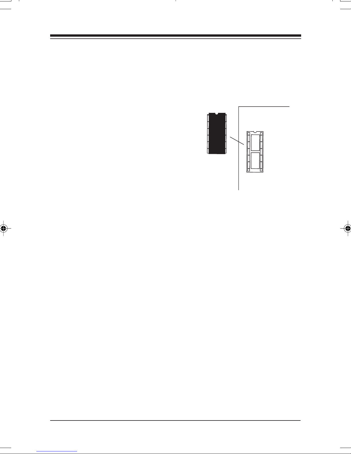
4848
48
4848
Appendix D: Installing Boot RAppendix D: Installing Boot R
Appendix D: Installing Boot R
Appendix D: Installing Boot RAppendix D: Installing Boot R
Installing the ODI Boot RInstalling the ODI Boot R
Installing the ODI Boot R
Installing the ODI Boot RInstalling the ODI Boot R
compacompa
compa
compacompa
1. Obtain a boot ROM
2. Put the Boot ROM in the 28-pin
socket. Make sure you line up the
notch on the Boot ROM with the
notch on the socket.
3. To enable the Boot ROM, run the
BENCFG utility. Select Mode
Settings, then Boot ROM Enable.
4. The Boot ROM will work only with the following three
configurations:
tible)tible)
tible)
tible)tible)
OM (mOM (m
OM (m
OM (mOM (m
OMsOMs
OMs
OMsOMs
ust be NE2000-ust be NE2000-
ust be NE2000-
ust be NE2000-ust be NE2000-
U3
I/O INTERRUPT BOOT ROM
ADDRESS
CONFIG.1 300h 3 C800h
CONFIG.2 320h 5 CC00h
CONFIG.3 340h 4 D000h
5. Follow the Boot ROM installation procedure given in the
Novell Installation manual to create the Boot Image on the
Novell Server.
6. Remove any boot drives from the workstation (A:, C:) and reboot the system.
BOCA NETBOCA NET
BOCA NET
BOCA NETBOCA NET
-8 Ethernet Kit-8 Ethernet Kit
-8 Ethernet Kit
-8 Ethernet Kit-8 Ethernet Kit
Page 49
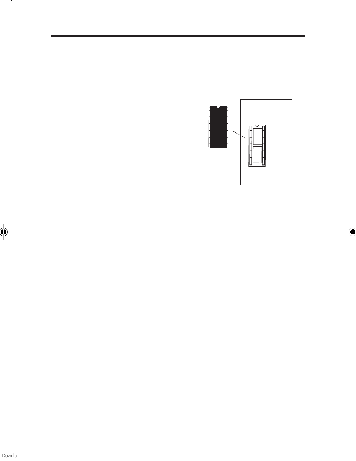
4949
49
4949
Installing the NDIS Boot RInstalling the NDIS Boot R
Installing the NDIS Boot R
Installing the NDIS Boot RInstalling the NDIS Boot R
1. Obtain a boot ROM.
2. Put the Boot ROM in the 28-pin
socket. Make sure you line up the
notch on the Boot ROM with the
notch on the socket.
3. To enable the Boot ROM, run the
BENCFG utility. Select Mode
Settings, then Boot ROM Enable.
4. The Boot ROM will work only with the following three
configurations:
I/O INTERRUPT BOOT ROM
OMOM
OM
OMOM
U3
ADDRESS
CONFIG.1 300h 3 C800h
CONFIG.2 320h 5 CC00h
CONFIG.3 340h 4 D000h
5. Follow the LAN Manager server setup procedure for starting
remote booting services on the LAN Manager server. Refer to
the LAN Manager documentation.
6. Remove any boot drives from the workstation (A:, C:) and reboot the system.
Installing Boot RInstalling Boot R
Installing Boot R
Installing Boot RInstalling Boot R
OMsOMs
OMs
OMsOMs
Page 50

5050
50
5050
Appendix E: FCC ComplianceAppendix E: FCC Compliance
Appendix E: FCC Compliance
Appendix E: FCC ComplianceAppendix E: FCC Compliance
This equipment has been tested and found to comply with the
limits for a
FCC Rules. These limits are designed to provide reasonable
protection against harmful interference when the equipment is
operated in a commercial environment.
This equipment generates, uses, and can radiate radio
frequency energy and, if not installed and used in accordance
with the instructions, may cause harmful interference to radio
communications. Operation of this equipment in a residential
area is likely to cause harmful interference in which case users
will be required to correct the interference at their own
expense.”
CHANGES OR MODIFICACHANGES OR MODIFICA
CHANGES OR MODIFICA
CHANGES OR MODIFICACHANGES OR MODIFICA
NOT EXPRESSLNOT EXPRESSL
NOT EXPRESSL
NOT EXPRESSLNOT EXPRESSL
COULD VOID YOUR AUTHORITY TO OPERACOULD VOID YOUR AUTHORITY TO OPERA
COULD VOID YOUR AUTHORITY TO OPERA
COULD VOID YOUR AUTHORITY TO OPERACOULD VOID YOUR AUTHORITY TO OPERA
Class A Class A
Class A digital device, pursuant to Part 15 of the
Class A Class A
TIONS TO THIS EQUIPMENTTIONS TO THIS EQUIPMENT
TIONS TO THIS EQUIPMENT
TIONS TO THIS EQUIPMENTTIONS TO THIS EQUIPMENT
Y APPROVED BY THE MANUFY APPROVED BY THE MANUF
Y APPROVED BY THE MANUF
Y APPROVED BY THE MANUFY APPROVED BY THE MANUF
ACTURERACTURER
ACTURER
ACTURERACTURER
TE THETE THE
TE THE
TE THETE THE
EQUIPMENTEQUIPMENT
EQUIPMENT
EQUIPMENTEQUIPMENT
BOCA NETBOCA NET
BOCA NET
BOCA NETBOCA NET
-8 Ethernet Kit-8 Ethernet Kit
-8 Ethernet Kit
-8 Ethernet Kit-8 Ethernet Kit
..
.
..
Page 51

5151
51
5151
Appendix F: SerAppendix F: Ser
Appendix F: Ser
Appendix F: SerAppendix F: Ser
If your Boca product requires service, first contact the authorized
dealer from whom you purchased the product. If the dealer is unable
to assist you, and you must contact Boca Research, Inc., please follow
the instructions below.
Our electronic BBS is available 24 hours a day at (561) 241-1601 and
will support data transmission speeds up to 33.6Kbps with settings of
N, 8, 1. If you have a modem, the BBS may be helpful (especially
during off hours) if you have a question about product settings or
compatibility, or if you wish to download driver software or utilities.
If the Troubleshooting section did not resolve your problem, you may
call our technical support staff for assistance. If you haven’t referred
to the Troubleshooting section, there’s a good chance the solution to
your problem is there.
vicing vicing
vicing
vicing vicing
YY
our Boca Prour Boca Pr
Y
our Boca Pr
YY
our Boca Prour Boca Pr
oductoduct
oduct
oductoduct
NOTE: CALLING TECHNICALNOTE: CALLING TECHNICAL
NOTE: CALLING TECHNICAL
NOTE: CALLING TECHNICALNOTE: CALLING TECHNICAL
AND ACCURAAND ACCURA
AND ACCURA
AND ACCURAAND ACCURA
PROBLEM MAPROBLEM MA
PROBLEM MA
PROBLEM MAPROBLEM MA
FRUSTRAFRUSTRA
FRUSTRA
FRUSTRAFRUSTRA
1. When calling Boca Research Technical Support, have the following
information available:
Board name and part #
(located on the board)
Computer manufacturer
Computer model
Peripherals in system
Operating system and version
2. Call Boca Research Technical Support Department between the
hours of 8:00 a.m. and 6:30 p.m. Monday through Friday EST at
(561) 241-8088. A technical support specialist will be available to
discuss the problem(s) you are experiencing. If factory service is
required, you will be given a Return Merchandise Authorization
TING FOR YOU.TING FOR YOU.
TING FOR YOU.
TING FOR YOU.TING FOR YOU.
TE INFORMATE INFORMA
TE INFORMA
TE INFORMATE INFORMA
Y BE BOTH TIME-CONSUMING ANDY BE BOTH TIME-CONSUMING AND
Y BE BOTH TIME-CONSUMING AND
Y BE BOTH TIME-CONSUMING ANDY BE BOTH TIME-CONSUMING AND
SUPPOR SUPPOR
SUPPOR
SUPPOR SUPPOR
TION CONCERNING YOURTION CONCERNING YOUR
TION CONCERNING YOUR
TION CONCERNING YOURTION CONCERNING YOUR
If you suspect a problem with aIf you suspect a problem with a
If you suspect a problem with a
If you suspect a problem with aIf you suspect a problem with a
specific program or softwarespecific program or software
specific program or software
specific program or softwarespecific program or software
package, make note of the name,package, make note of the name,
package, make note of the name,
package, make note of the name,package, make note of the name,
version or release numberversion or release number
version or release number
version or release numberversion or release number
manufacturer of the software.manufacturer of the software.
manufacturer of the software.
manufacturer of the software.manufacturer of the software.
T WITHOUT COMPLETET WITHOUT COMPLETE
T WITHOUT COMPLETE
T WITHOUT COMPLETET WITHOUT COMPLETE
, and, and
, and
, and, and
Servicing Your Boca Product
Page 52

5252
52
5252
(RMA) number.
packagepackage
package when you return the item(s) for service and reference it on
packagepackage
any correspondence included in the package. Boca Research, Inc.
will return any product which is not accompanied by an RMA
number.
3. Refer to the Warranty Statement if the product is covered under the
five-year Boca Research Limited Warranty.
4. Certain parts will not be covered under the Boca Research, Inc.
Limited Warranty. Dealer installed parts are warranted by the
dealer. Parts which you have installed yourself are covered only by
the suppliers warranties. In these cases, Boca Research, Inc. can
identify which parts are defective, but will not replace such parts
until we receive written authorization from you. Cost of parts and
labor involved in making such repairs will be billed to you C.O.D.
5. When returning the product to Boca Research, Inc. for repairs,
please be sure to include:
• the BOCA NET-8 concentrator and/or network cards only
• your name
• your return street address (for UPS purposes)
• your phone number
• the RMA number mentioned above.
Please place this number on the outside of thePlease place this number on the outside of the
Please place this number on the outside of the
Please place this number on the outside of thePlease place this number on the outside of the
Package the product securely in a container equivalent to the
original packaging, and insure the package to protect against loss
or damage during transit. Shipping charges must be prepaid;
C.O.D. shipments will not be accepted. Please use the address
below for all correspondence:
RMA Department - RMA # ___________RMA Department - RMA # ___________
RMA Department - RMA # ___________
RMA Department - RMA # ___________RMA Department - RMA # ___________
6. If the repairs performed on your product were covered by the
warranty, Boca Research, Inc. will return it prepaid via UPS.
BOCA NETBOCA NET
BOCA NET
BOCA NETBOCA NET
-8 Ethernet Kit-8 Ethernet Kit
-8 Ethernet Kit
-8 Ethernet Kit-8 Ethernet Kit
Boca Research, Inc.Boca Research, Inc.
Boca Research, Inc.
Boca Research, Inc.Boca Research, Inc.
6500 W6500 W
6500 W
6500 W6500 W
Boca Raton, FL 33487-2841Boca Raton, FL 33487-2841
Boca Raton, FL 33487-2841
Boca Raton, FL 33487-2841Boca Raton, FL 33487-2841
est Rogers Circleest Rogers Circle
est Rogers Circle
est Rogers Circleest Rogers Circle
Page 53

5353
53
5353
Appendix G: Appendix G:
Appendix G:
Appendix G: Appendix G:
Limited WLimited W
Limited W
Limited WLimited W
Boca Research, Inc. (BRI) warrants to the original buyer of this BRI pr oduct that the
hardware is free of defects in materials and workmanship for a period of five (5)
years from the date of purchase from BRI or an authorized dealer (“the Warranty
Period”). Should the product fail to be in working order at any time during the fiveyear period, BRI, will at its option, repair or replace this product as described
below, provided that in BRI’s sole determination the part or product has not been
abused, misused, repair ed, or modified.
All products will be serviced and returned via ground at no charge to customers.
All returns for limited warranty service require a Return Merchandise
Authorization (RMA). All customers ar e r equir ed to demonstrate pr oof of purchase
when requesting an RMA. The period of warranty commences on the date of
purchase. A dated copy of the sales slip must be included with the returned
merchandise.
arrantyarranty
arranty
arrantyarranty
WW
arrantyarranty
W
arranty
WW
arrantyarranty
Products which r equire Limited Warranty service during the warranty period
should be delivered to BRI at the address in the Appendix (Servicing Your Boca
Product) with pr oof of purchase, copy of canceled check (if any), and the Return
Merchandise Authorization (RMA) number pr ovided by BRI Technical Support.
Refer to the Appendix in this manual. Replacement parts or complete products will
be furnished on an exchange basis only. Replaced parts and/or products become
the property of BRI.
If the returned product is sent by mail, the purchaser agrees to prepay shipping
charges, insure the product or assume the risk of loss or damage which may occur
in transit, and to use a shipping container equivalent to the original packaging. BRI
does not make any warranties in respect to the pr oduct, either expr essed or
implied, including no implied warranties of merchantability or fitness for a
particular purpose, except as expressly provided in this agreement. If any labor,
repair, or parts replacement is required because of accident, negligence, misuse,
theft, vandalism, fire, water or other peril; or because of conditions outside of
specifications, including, but not limited to, electrical power, temperature,
humidity or dust; or by moving, repair relocation, or alteration not performed by
BRI, or by any other cause other than normal use, the warranty and maintenance
obligations provided herein shall not apply.
Warranty
Page 54

5454
54
5454
BRI SHALLBRI SHALL
BRI SHALL
BRI SHALLBRI SHALL
CONSEQUENTIAL DAMAGES OR FOR LOSS, DAMAGE, OR EXPENSECONSEQUENTIAL DAMAGES OR FOR LOSS, DAMAGE, OR EXPENSE
CONSEQUENTIAL DAMAGES OR FOR LOSS, DAMAGE, OR EXPENSE
CONSEQUENTIAL DAMAGES OR FOR LOSS, DAMAGE, OR EXPENSECONSEQUENTIAL DAMAGES OR FOR LOSS, DAMAGE, OR EXPENSE
DIRECTLDIRECTL
DIRECTL
DIRECTLDIRECTL
INABILITY TO USE THE EQUIPMENT EITHER SEPINABILITY TO USE THE EQUIPMENT EITHER SEP
INABILITY TO USE THE EQUIPMENT EITHER SEP
INABILITY TO USE THE EQUIPMENT EITHER SEPINABILITY TO USE THE EQUIPMENT EITHER SEP
COMBINACOMBINA
COMBINA
COMBINACOMBINA
OR LOSS OR DESTRUCTION OF OTHER PROPEROR LOSS OR DESTRUCTION OF OTHER PROPER
OR LOSS OR DESTRUCTION OF OTHER PROPER
OR LOSS OR DESTRUCTION OF OTHER PROPEROR LOSS OR DESTRUCTION OF OTHER PROPER
CAUSE.CAUSE.
CAUSE.
CAUSE.CAUSE.
Boca's products are manufactured from new and serviceable used parts testedBoca's products are manufactured from new and serviceable used parts tested
Boca's products are manufactured from new and serviceable used parts tested
Boca's products are manufactured from new and serviceable used parts testedBoca's products are manufactured from new and serviceable used parts tested
to Boca Research's quality assurance standards. If the product proves to beto Boca Research's quality assurance standards. If the product proves to be
to Boca Research's quality assurance standards. If the product proves to be
to Boca Research's quality assurance standards. If the product proves to beto Boca Research's quality assurance standards. If the product proves to be
defective, Boca Research will bear the costs of labor and materials fordefective, Boca Research will bear the costs of labor and materials for
defective, Boca Research will bear the costs of labor and materials for
defective, Boca Research will bear the costs of labor and materials fordefective, Boca Research will bear the costs of labor and materials for
hardware replacement or repair during the above specified warranty period.hardware replacement or repair during the above specified warranty period.
hardware replacement or repair during the above specified warranty period.
hardware replacement or repair during the above specified warranty period.hardware replacement or repair during the above specified warranty period.
Boca Research or its Authorized Service Providers shall have the option toBoca Research or its Authorized Service Providers shall have the option to
Boca Research or its Authorized Service Providers shall have the option to
Boca Research or its Authorized Service Providers shall have the option toBoca Research or its Authorized Service Providers shall have the option to
replace any defective part(s) with new part(s) orreplace any defective part(s) with new part(s) or
replace any defective part(s) with new part(s) or
replace any defective part(s) with new part(s) orreplace any defective part(s) with new part(s) or
Research, with serviceable used parts that are equivalent to new parts inResearch, with serviceable used parts that are equivalent to new parts in
Research, with serviceable used parts that are equivalent to new parts in
Research, with serviceable used parts that are equivalent to new parts inResearch, with serviceable used parts that are equivalent to new parts in
performance. Boca Research shall also have the option to replace anyperformance. Boca Research shall also have the option to replace any
performance. Boca Research shall also have the option to replace any
performance. Boca Research shall also have the option to replace anyperformance. Boca Research shall also have the option to replace any
defective product(s) with functionally equivalent product(s).defective product(s) with functionally equivalent product(s).
defective product(s) with functionally equivalent product(s).
defective product(s) with functionally equivalent product(s).defective product(s) with functionally equivalent product(s).
This warranty shall not be applicable to the extent that any provision of this
warranty is prohibited by any Federal, state, or municipal law which cannot be
preempted. This warranty gives you specific legal rights, and you may also have
other rights which vary from state to state.
NOT BE LIABLE FOR ANY SPECIAL, INCIDENT NOT BE LIABLE FOR ANY SPECIAL, INCIDENT
NOT BE LIABLE FOR ANY SPECIAL, INCIDENT
NOT BE LIABLE FOR ANY SPECIAL, INCIDENT NOT BE LIABLE FOR ANY SPECIAL, INCIDENT
Y OR INDIRECTLY OR INDIRECTL
Y OR INDIRECTL
Y OR INDIRECTLY OR INDIRECTL
TION WITH OTHER EQUIPMENTTION WITH OTHER EQUIPMENT
TION WITH OTHER EQUIPMENT
TION WITH OTHER EQUIPMENTTION WITH OTHER EQUIPMENT
Y ARISING FROM CUSTOMER’S USE OF ORY ARISING FROM CUSTOMER’S USE OF OR
Y ARISING FROM CUSTOMER’S USE OF OR
Y ARISING FROM CUSTOMER’S USE OF ORY ARISING FROM CUSTOMER’S USE OF OR
ARAARA
ARA
ARAARA
, OR FOR PERSONAL, OR FOR PERSONAL
, OR FOR PERSONAL
, OR FOR PERSONAL, OR FOR PERSONAL
TYTY
, OR FROM ANY OTHER, OR FROM ANY OTHER
TY
, OR FROM ANY OTHER
TYTY
, OR FROM ANY OTHER, OR FROM ANY OTHER
, at the option of Boca, at the option of Boca
, at the option of Boca
, at the option of Boca, at the option of Boca
TELTEL
TEL
TELTEL
AL, ORAL, OR
AL, OR
AL, ORAL, OR
Y OR INY OR IN
Y OR IN
Y OR INY OR IN
INJUR INJUR
INJUR
INJUR INJUR
YY
Y
YY
CopyrightCopyright
Copyright
CopyrightCopyright
©1997. Boca Research, Inc. All rights reserved. No reproduction of
this document in any form is allowed without permission in writing
from Boca Research, Inc. Boca Research is not liable for any damages
resulting from technical or editorial errors or omissions contained in
this document. The information in this manual is subject to change
without notice. Revisions to the product(s) in this manual may occur
at any time without notice.
TT
rademarksrademarks
T
rademarks
TT
rademarksrademarks
All Boca Research products are trademarks of Boca Research, Inc. All
other references to computer systems, software, and peripherals use
trademarks owned by their respective manufacturers.
Publication Date: OctoberPublication Date: October
Publication Date: October
Publication Date: OctoberPublication Date: October
Printed in the U.S.A.
BOCA NETBOCA NET
BOCA NET
BOCA NETBOCA NET
-8 Ethernet Kit-8 Ethernet Kit
-8 Ethernet Kit
-8 Ethernet Kit-8 Ethernet Kit
, 1997, 1997
, 1997
, 1997, 1997
9370.P65
Page 55

5555
55
5555
Page 56

5656
56
5656
BOCA NETBOCA NET
BOCA NET
BOCA NETBOCA NET
-8 Ethernet Kit-8 Ethernet Kit
-8 Ethernet Kit
-8 Ethernet Kit-8 Ethernet Kit
Manual PManual P
Manual P
Manual PManual P
10/97-110/97-1
10/97-1
10/97-110/97-1
arar
ar
arar
t No.t No.
t No.
t No.t No.
9370 9370
9370
9370 9370
 Loading...