

1

2
On-Line EXPRESS

Before You Begin your Installation
The product you have purchased is designed to be
easily installed into most IBM PC or compatible
systems. Many products have large, easy-to-read
legends to allow for the easy configuring of the
product. This installation manual contains detailed
instructions. Most included software has automatic
installation programs to place the software correctly onto your
computer. However, as all computers are configured differently, you
may be required to perform some basic DOS or Windows tasks. If you
are not familiar with basic DOS commands such as DIR, CD, or EDIT,
3
you should check your DOS manual, or seek assistance from you local
computer dealer to install the product.
How to get Technical Assistance
The dealer that you purchased this product or your computer from is
the first place you should go for technical assistance. The dealer is
usually the most qualified source of help, and
is most familiar with your system and how
this product should be installed. Many dealers
have customer service and technical support
programs, with varying levels of support offered, depending on your
needs and computer knowledge. Please contact the dealer first
whenever a problem occurs.
If your Dealer Can’t Assist you
If you can’t get assistance from your dealer, the manufacturer provides
varying levels of technical assistance as summarized on the following
page.
4
2
3
1
4
5
6
7
9
8
2
3
1
4
5
6
7
9
8
Boca BBS
407-241-1601
Standard Free
Technical Support
407-241-8088
Technical
Support Fax
407-997-0918
Priority Service
900-555-4900
($2 per minute)
Automated Fax Retrieval System
407-995-9456
The Standard Free Technical
Support number is for quick
answers to specific inquiries on
product features and technical
questions (call 407-241-8088; MF, 8 am to 6:30 pm EST). Direct
access to technical support
representatives is provided on a
limited basis. If you require
immediate attention or in-depth
help with the installation of the
product, please call our 900priority support number for
service. This number gives you immediate access to senior-level
technicians. The number is 900-555-4900. You will be charged $2.00 per
On-Line Support!
CompuServe: GO BOCA
Internet:
email: support@boca.org
on the World-wide WEB:
http://www.boca.org
minute. The charges will appear on your next phone bill.
Damaged or Missing Items
We use many world-class quality assurance programs to ensure the
product you purchased is of the highest caliber. Sometimes, however, a
component may be missing from the box, or is damaged or corrupt in
some way. If this happens, immediately return the entire package to
your place of purchase so you may exchange it for a new one. Your
dealer should be able to provide you with an exchange far more quickly
than by contacting us directly. If for some reason you are unable to
return the product directly to its place of purchase, refer to the
“Servicing Your Product” and “Warranty” sections in this manual for
instructions.
On-Line EXPRESS

Contents
Section One: EXPRESS Install ................................................ 6
Section Two: Product Overview ...........................................13
Section Three: Troubleshooting ........................................... 16
Appendix A: Command and Protocol Reference ............. 21
Appendix B: Technical Specifications................................ 25
Appendix C: Compliance Information ...............................26
5
Appendix D: RPI Software Developers.............................. 30
Command Quick Reference .................................................. 31
Servicing Your Boca Product ................................................. 46
Warranty Information ............................................................. 49
Copyright
©1995. All rights reserved. No reproduction of this document in any form is
allowed without permission in writing from Boca Research, Inc. Boca Research
is not liable for any damage resulting from technical or editorial errors or
omissions contained in this document. The information in this manual is subject
to change without notice. Revisions to the product(s) in this manual may occur
at any time without notice.
Trademarks
All Boca Research products are trademarks of Boca Research, Inc. All other
references to computer systems, software, and peripherals use trademarks
owned by their respective manufacturers.
Publication Date: March, 1995
Printed in the U.S.A. M144AE.PM5
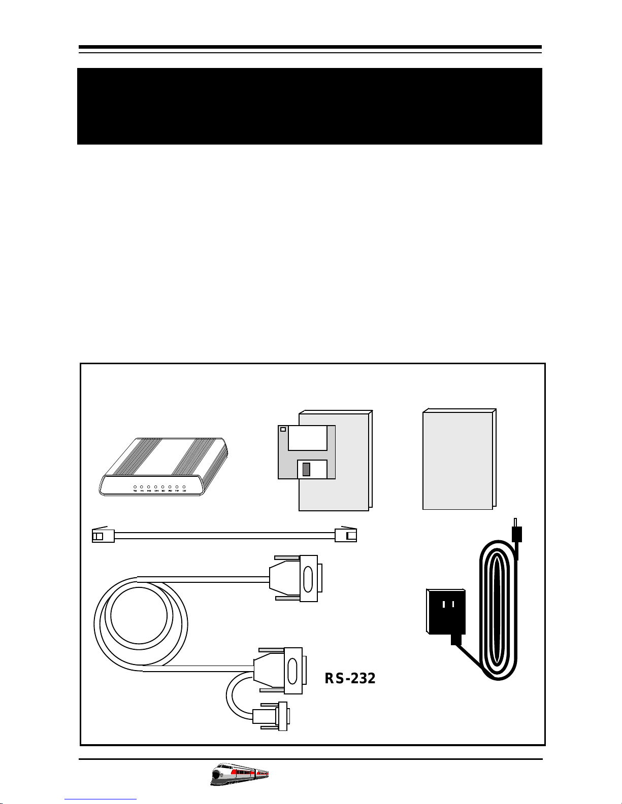
6
EXPRESS Install
Congratulations on the purchase of your On-Line
EXPRESS 14.4 (M144AI) from Boca Research, Inc., a
leader in high-tech computer enhancement products.
Get started with the streamlined EXPRESS Install
provided here. The balance of the manual contains a
product overview, troubleshooting, technical
specifications, and a comprehensive AT command
reference. Make sure you have received the following
items:
EXTERNAL
MODEM
RJ-11 CABLE
COMMUNICATIONS
SOFTWARE & MANUAL
AC POWER
ADAPTER
INSTALLATION
MANUAL
On-Line EXPRESS
RS-232 ADAPTER
CABLE TO SERIAL
PORT (9- or 25-pin
connector)
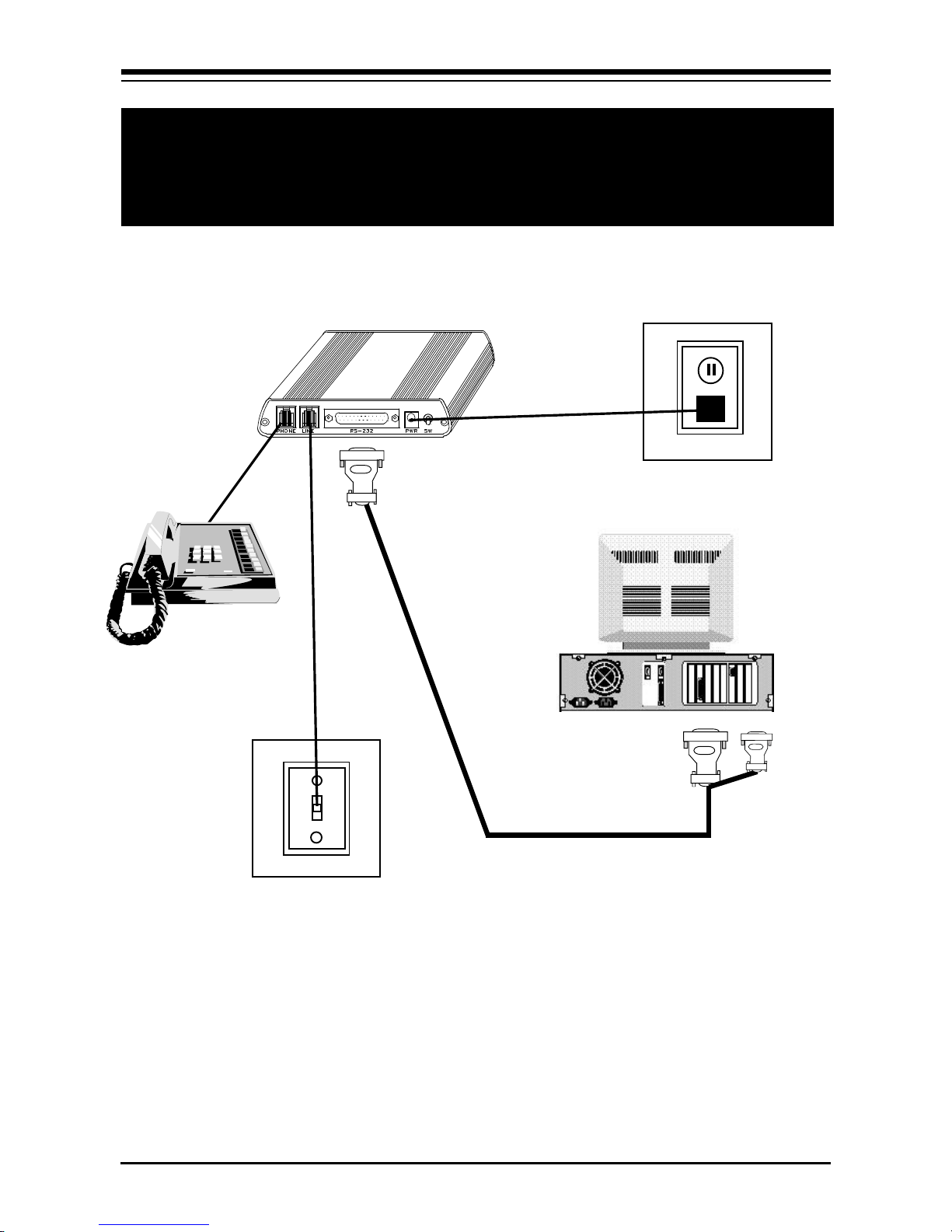
Installation Overview
MODEM
AC ADAPTER
7
PHONE
(OPTIONAL)
REAR OF
SYSTEM
RS-232 ADAPTER CABLE
TO SERIAL PORT (9- or 25-
PHONE
JACK
pin connector)
For details on the procedure outlined above, continue
with the EXPRESS Install on pages 8-12.
EXPRESS Install

8
Installing the On-Line EXPRESS Modem
1. Turn off your computer and all peripheral devices.
2. Examine the back of the modem and review the
interfaces as shown below.
3. Check to make sure that the power switch is OFF
(RIGHT). Then plug the small end of the power
adapter into the power jack on the back of the
modem and plug the power adapter into a standard
120V AC wall socket.
Power connector
Phone jack
Line jack
Power
switch
RS-232 connector
AC adapter
Power jack
4. Disconnect your present phone cord from the wall
jack. Plug the end of the phone cord that came with
the modem into the wall jack, and the other end
into the RJ-11 jack at the rear of the modem marked
LINE.
On-Line EXPRESS
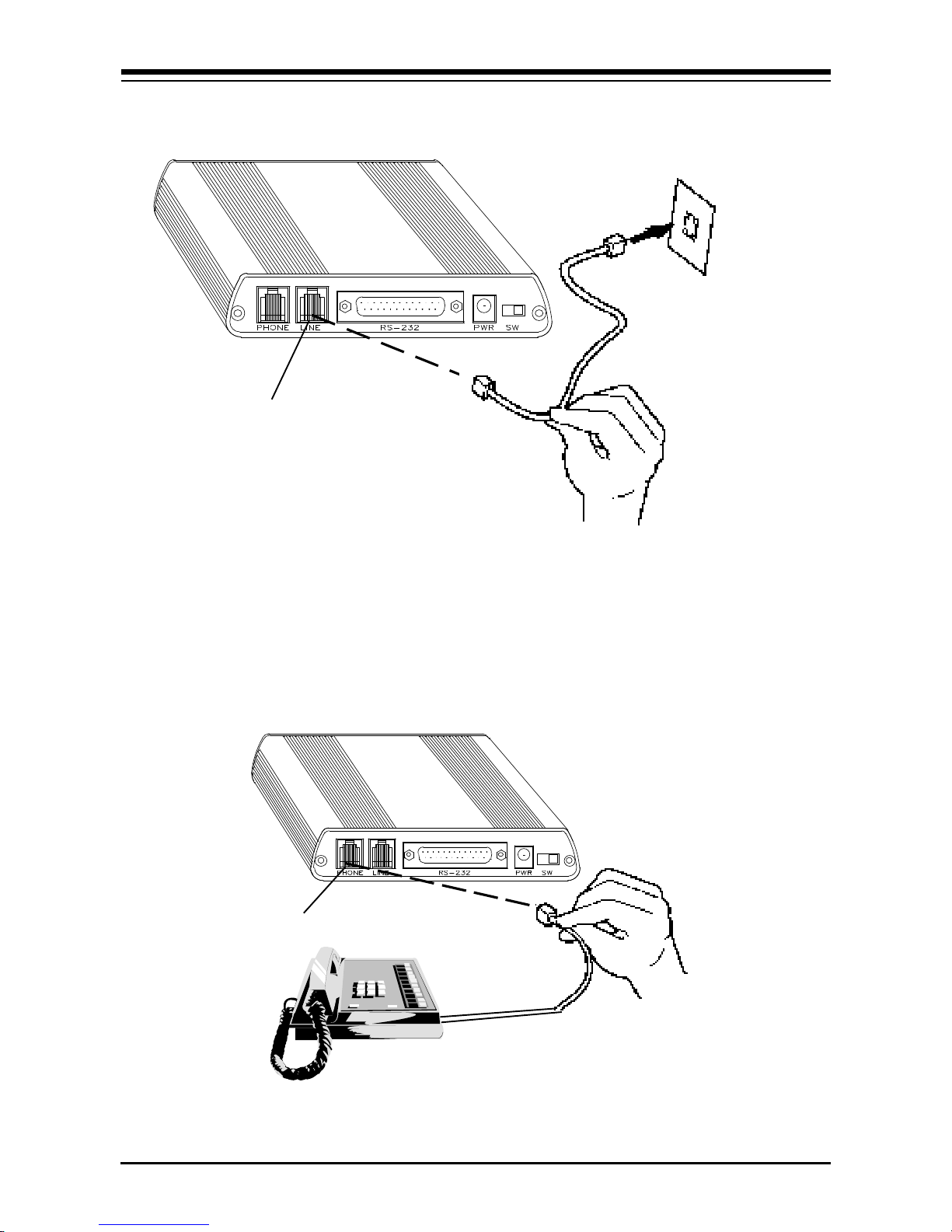
Line jack
9
Wall
phone
jack
RJ-11 cable
If you want to keep your telephone connected for
conventional calls, plug its cord into the other jack at
the rear of the modem labeled PHONE.
Phone jack
EXPRESS Install

10
5. Lastly, connect the modem to the computer’s serial
port with the serial cable. The modem is now ready
to be tested and operated. Turn your computer on
now, then switch ON the modem (switch in the
LEFT position).
Serial cable
RS-232 connector
6. Install your communications software now.
Depending on the software you choose, refer to the
appropriate manual for start-up and configuration.
Following that, you are ready to test the connection.
Testing the Connection
1. Note the status indicators as explained on the
following page, then continue.
On-Line EXPRESS

Indicator Definition Status
TM Test Mode FLASHES when modem is in
test mode and if any errors are
detected.
AA Auto Answer ON when in Auto Answer mode
and when online with the host
modem.
HS High speed ON when the modem is
powered on or communicating
with another modem at
4800bps or faster.
11
OH Off Hook ON when the modem
takes control of the telephone
line to establish a data link.
SD Send Data FLASHES when a data bit is
sent to the modem by
the computer.
RD Received FLASHES when a data bit is
Data received from the phone line,
or when the modem sends
result codes to the computer.
TR Terminal ON when the modem receives
Ready a data terminal ready signal
from the computer via the RS232 cable.
CD Carrier ON when the modem receives
Detect a valid data signal (carrier)
from a remote modem. Ready
for data transmission.
EXPRESS Install

12
2. If you are using a telephone, check for a dial tone
using the telephone handset. If a dial tone is heard,
continue with the next step. If you do not hear a dial
tone, check the connections you made on pages 8-10,
or refer to Troubleshooting (Section Three).
3. Your communications software should already be
loaded as instructed on page 10. If not, start it now
and enter terminal mode.
IMPORTANT: If you are not in terminal mode and you type
AT commands at the DOS prompt, a “Bad Command or File
Name” message will result.
4. Type in the command ATZ followed by ENTER and
the modem will respond with OK. If the modem does
not respond with OK, refer to the Troubleshooting
section of this manual.
5. Start your communications software and enter
terminal mode; AT commands typed in at the DOS
prompt will result in a “Bad command or file name”
message. Type ATH1 followed by ENTER and you
should hear a dial tone from the speaker on the
modem.
6. Type ATH followed by ENTER to put the modem on
hook. This confirms that the modem has been
successfully installed into the computer.
7. Your modem is now ready for use. Continue now
with your communications software and
documentation.
On-Line EXPRESS

Section Two: Pr oduct Overview
The On-Line
EXPRESS modem by
Boca Research, Inc.
combines high-
14.4
speed data, modem,
and fax capability on
a single device. It also features V.32bis, which
provides high-speed data transmission.
13
Features
• Data transmission rates of 14.4K, 12K, 9600, 7200,
4800, 2400, 1200, or 300bps.
• Programmable speaker volume control
• Auto-speed sensing.
• Data throughput up to 57,600bps (with RPI
support).
• Group 3 send and receive fax capability with
support for Class 1 and Class 2 fax commands.
• Full error control (V.42 LAPM, MNP2-4) and data
compression is available through host
communications software that supports RPI. See
Appendix E for a list of software developers who
support this protocol.
• 100% data compatibility with the Hayes ‘AT’
command set.
Product Overview

14
The Appendix features a discussion of standard and
extended ‘AT’ commands and S-Registers as well as
high-level protocols.
Installation Hints
Your modem has been pre-set at the factory for
optimum performance. All defaults are set to allow
the modem to negotiate the best possible connection.
Because of these factory defaults, the suggested
initialization (INIT) string is: ATZ. You should change
the INIT string in all of your software packages to this
INIT string.
If you want to custom configure your stored profiles,
we suggest that you always start out with an
AT&F&C1&D2 before customizing other commands.
This string will reset the modem to the factory
defaults as well as reset some other basic settings. If
modem performance suffers after modifying settings,
send the INIT string above (AT&F...&D2) to the
modem.
Notes on Performance
To get optimum performance from your modem, the
phone line quality over which you are transmitting
and receiving must be reliable and relatively free of
“noise”.
On-Line EXPRESS

15
Operational Requirements
The modem has few requirements and is easy to use.
Be sure to read the information in the Appendix about
connecting to the phone company. In addition, note
the following:
• The communication settings are controlled by the
software that manipulates the serial interface
present in your system. The external modem is
connected to that interface.
• Operating the modem with a computer requires
communication software, either as a stand-alone
product as included here, or as part of an
application program.
• The modem takes a DB-25 (25-pin male connector),
but computer equipment varies. Check the serial
ports at the rear of your system.
• The modem uses an existing serial port on the back
panel of your computer. It can be a 9-pin or 25-pin
D-shell connector. Use the dual end (25-pin or 9-pin)
of the cable supplied with your modem to connect
to your system’s serial port.
Product Overview

16
Section Three: Troubleshooting
This section lists common problems that may be
encountered and their possible solutions.
SYMPTOM POSSIBLE REMEDY
No dial tone.
Modem will not
connect to
another modem.
• Verify that you have cables plugged in
correctly as instructed in Section Two.
• Connect a telephone set directly to the
wall jack and check for a dial tone. If
no dial tone is heard, the telephone line
is not working. Contact the telephone
company.
• Check the connections between the
modem and the computer, and the
modem and the telephone line.
• Make sure the telephone jack is
operational as described above.
• The telephone line may be in use at a
different extension.
No response
when you type in
AT commands
On-Line EXPRESS
• Perhaps the number you have called
does not reach a modem, or the remote
modem may not be set up to respond.
• There may be a conflicting port
address. Re-configure the modem’s
COM port address.

SYMPTOM POSSIBLE REMEDY
No response when
you type in AT
commands (contd)
• Verify that the communication
software is set to the same
communications port where your
modem is attached (e.g., COM1,
COM2). Check IRQ settings in your
software.
• Try typing AT&F to r eset the modem
to its factory defaults.
• Move the modem to another serial
port (power down the host computer
first). If the modem works after
being moved, it’s likely the problem
is not with the modem.
17
AT commands not
visible.
After data connection
is established, data is
displayed as garbled
characters.
• Make sure the echo command is set
to ON. Change to echo with the ATE
command.
• Make sure the local (yours) and
remote modem configurations are
compatible.
• Verify that both modems are
operating with the same settings,
speed, data, parity, and stop bits.
• The software may not be set for
correct terminal emulation.
Configure software to correct type.
ANSI terminal emulation is most
commonly used.
Troubleshooting

18
SYMPTOM POSSIBLE REMEDY
After data
connection is
established, data
is displayed as
garbled
characters.
(contd)
The modem
does not answer
an incoming
call.
• Power down your system and re-run your
communications software. Check software
settings.
• Exit the communications program and
restart it.
• You may not have enabled auto-answer.
Use your software to enable this function.
• If you have an answering machine, it may
be answering before the modem can. Turn
the answering machine off, or, use the
software to set auto-answer to respond in
fewer rings than the answering machine.
Modem
disconnects
while on-line.
My software
does not support
a speed of
14.4Kbps.
• Check for any loose connections.
• Re-try the connection by dialing the
number several times. You may be
experiencing line interference.
• An incoming call may have broken the
connection if a call-waiting feature was
enabled. Disable call-waiting and try again.
• 14.4Kbps refers to modem to modem
speed. Select 19.2Kbps (or faster if your
hardware supports it) for computer to
modem speed.
On-Line EXPRESS

SYMPTOM POSSIBLE REMEDY
19
I am having
trouble getting
my init string to
work.
My 2400bps (or
other modem)
worked with my
system but the
this modem does
not.
I need the
modem to
connect at a
• Init strings are primarily personal
preferences. Use the most basic one that
can get the job done. See Installation
Hints, page 8.
• Review earlier suggestions.
• Make sure you use software included with
modem.
• Send an AT&Q6N0S37=n where n= 9 for
9600, 6 for 2400, 5 for 1200, 1 for 300bps.
certain speed.
Connection
Errors.
• Try connecting at a lower speed (e.g.,
9600 or 2400bps).
• Turn off err or correction/compression
with an AT&Q6%C0 command.
• Noisy/poor line conditions may prohibit
connection. Have your phone company
test your lines.
• Verify that the modem at the other end is
up to date and compliant with current
CCITT and Bell standards.
Troubleshooting

20
SYMPTOM POSSIBLE REMEDY
Problem
Connecting to
On-line
subscription
services.
• Some on-line services require that your
modem be configured to run with error
correction and data compression turned
OFF. The easiest way to accomplish this
is by using the command AT&Q6 and
setting the communication software to
the correct baud rate for the service you
are calling (e.g., 2400, 9600bps). If you
still have problems connecting, try
forcing the modem to connect up at the
slower speed with the commands
AT&Q6F5 for 2400 baud, and AT&Q6F8
for 9600 baud services.
On-Line EXPRESS

21
Appendix A: Command/Protocol Overview
In most cases, your communications software will set
and control the operation of your modem. Following
is a brief survey of the most commonly used Hayescompatible AT commands for use with your modem.
In addition, we’ve also provided information on
extended AT command sets, S-Registers, and
commands and registers for high-level protocols such
as V.32/V.32bis.
It will rarely be necessary to use ‘AT’ commands and
S-Registers in command mode. We include them here
for more advanced users who may prefer command
mode operation, or require special settings.
Hayes-compatible commands consist of a basic
command set and an extended command set. The
basic set involves functions such as dialing a number,
or putting the modem on-hook (i.e., replacing the
telephone handset).
Extended commands allow more sophisticated control
of the modem such as transmission speed, or initiating
high-level functions like data compression or error
correction. These functions are defined and controlled
by the available protocols mentioned above. A
protocol is a set of standards by which data
communications operate.
Command/Protocol Reference

22
Every AT command includes an “AT” prefix,
followed immediately by the command and, in many
cases, additional parameters. Multiple commands can
be entered at the same time from the DOS prompt.
AT Command[parameter]AT Command[parameter]
... PRESS ENTER
Example: ATH or ATH0 tells the modem to
disconnect
Extended commands were developed to provide
greater functionality and control over modem
operations. Their format is the same as the basic
command except that an additional parameter is
required following the AT prefix and before the
numerical parameter. This additional parameter
comes in three different forms:
Extended AT Commands:
the ampersand (&) character
the backslash (\) character
the percent ( %) character
Examples: AT&V tells the modem to display (view)
its configuration and user profile, providing the
modem has non-volatile RAM, meaning it can store
limited amounts of information when power is off.
AT%E1 tells the modem to monitor line quality.
On-Line EXPRESS

23
S-Registers
Modem command “language” also employs a set of
indicators or registers, which are various numerical
values all with a standard “S” prefix, hence SRegisters. To a large extent, the values defined in the
S-Registers regulate the operation of the modem and
the function of some commands in the AT command
set.
Example: S-Register 6, or S6=n, defines the length of
time the modem will wait for a dial tone. In this case
the acceptable range is 3-6 (in seconds) with a default
value of 5. With S6=3, the modem will wait three
seconds for a dial tone when going off-hook before
dialing the first digit of its telephone number.
Data Communication Protocols
This can be more than a little confusing. These
protocols represent various domestic and
international standards which enhance modem
performance and reliability. The protocols are
activated and controlled by a variety of extended AT
commands and S-Registers.
The “V-Dot” standards are more numerous, but have
a single origin: the Consulting Committee for
International and Telephone and Telegraph (or
CCITT). Some of the lower-level standards such as
Command/Protocol Reference

24
V.21 and V.22 have “domestic” equivalents as
developed by the former Bell System, also referred to
as Bell standards. The “V.Dot” standards may be
summarized as shown below:
V.21 The CCITT standard for 300bps communications.
Domestic modems follow the Bell 103 standard, but V.21 can
accept international calls at 300bps.
V.22 The CCITT standard for 1200bps communications. The
domestic equivalent is the Bell 212A standard.
V.22bis The CCITT standard for 2400bps.
V.23 CCITT for 1200bps with a 75bps back channel. This is
mostly used in Europe and South America.
V.32 CCITT standard for 9600bps and 4800bps
communications.
V.32bis CCITT standard for an extensive range of high-speed
modems operating at 14,400bps, 12Kbps, 9600bps, 7200bps,
and 4800bps.
V.42 CCITT standard for detection and negotiation for
LAPM (Link Access Procedure for Modems) error control. V.42
will also support MNP levels 2-4.*
V.42bis An extension of V.42 specifying the data compression
protocol for use with V.42.*
* See Appendix D for list of software developers who support
these protocols through RPI (Rockwell Protocol Interface)
On-Line EXPRESS

25
Appendix B: Technical Specifications
Modem Data Rate: 14.4K, 12K, 9600, 7200, 4800, 2400, 1200,
or 300bps
Fax Data Rate: 14.4K, 12K, 9600, 7200, 4800, 2400bps.
Compatibility: Modem Modulation Protocols
ITU-T: V.32bis, V.32, V.22 (2400bps),
V.21 (1200bps)
Bell: Bell 212A (1200bps), Bell 103 (300bps)
Fax Modulation Protocols
V.17 (14,400/12,000bps transmit and receive
V.29 (9600/7200bps) transmit and receive
V.27 ter (4800/2400bps) transmit and receive
V.21 channel 2 (300bps) transmit and receive
Diagnostics: Local/remote digital and analog loopback
Automatic power-on self-test
LED Status
Indicators: TM, AA, HS, OH, SD, RD, TR, CD
Physical and Electrical Characteristics
• Dimensions: 7 1/4" x 5 3/8" x 1 1/4"
• Power: 500 mA@ 5V
• 2 RJ-11 modular phone connectors
• RS-232 serial port
Operating Temperature Requirements:
Dry Bulb Temperature: 10-40
Relative Humidity: 8-80%
Storage: 1-60
o
C (50-104o F)
o
C (33.8-140o F)
Specifications

26
Appendix C: Compliance Information
FCC Statement:
“This device complies with part 15 of the FCC rules. Operation is
subject to the following two conditions:
(1) This device may not cause harmful interference.
(2) This device must accept any interference received including
interference that may cause undesired operation.
THIS UNIT COMPLIES WITH FCC PART 68 AS OF DATE OF
MANUFACTURE.
This equipment has been tested and found to comply with the limits
for a Class B digital device, pursuant to Part 15 of FCC rules. These
limits are designed to provide reasonable protection against harmful
interference in a residential installation. This equipment generates,
uses, and can radiate radio frequency energy and, if not installed in
accordance with the instructions, may cause harmful interference to
radio communications. However, there is no guarantee that
interference will not occur in a particular installation. If this
equipment does cause harmful interference to radio or television
reception, which can be determined by turning the equipment off and
on, the user is encouraged to try to correct the interference by one or
more of the following measures:
• Re-orient or relocate the receiving antennae.
• Increase the separation between the equipment and the receiver.
• Connect the equipment into an outlet on a circuit different from
that to which the receiver is connected.
• Consult the dealer or an experienced radio/TV technician for help.
Note: This unit was tested with shielded cables on the peripheral
devices. Shielded cables must be used with the unit to insure
compliance.
On-Line EXPRESS

27
Note: The manufacturer is not responsible for any radio or TV
interference caused by unauthorized modifications to this equipment.
Such modifications could void the user ’s authority to operate the
equipment.”
Notification to the Telephone Company
Notification to the telephone company is no longer required prior to
connecting the registered equipment but upon request from the
telephone company the user shall tell the telephone company which
line the equipment is connected to as well as the registration number
and the ringer equivalence of the registered protective circuitry. In
most, but not all areas, the sum of all RENs should be 5.0 or less. The
FCC Registration number and Ringer Equivalence number are printed
on the main chip in the center of the modem board.
Malfunction of the Equipment
In the event that the MODEM should fail to operate properly, the
customer shall disconnect the equipment from the telephone line to
determine if it is the customer ’s equipment which is not working
properly, or if the problem is with the MODEM, the user shall
discontinue use until it is repaired. In the event service is needed the
user should contact the vendor from whom you purchased the
MODEM.
Telephone Connection Requirements
Except for telephone company-provided ringers, all connections to
the telephone network shall be made through standard plugs and
standard telephone company-provided jacks, or equivalent, in such a
manner as to allow for easy and immediate disconnection of the
terminal equipment. Standard jacks shall also be arranged that, if the
plug connected thereto is withdrawn, no interference to the operation
of the equipment at the customer’s premises which remains
connected to the telephone network, shall occur by reason of such
withdrawal.
Incidence of Harm
Should terminal equipment or protective circuitry cause harm to the
telephone network, the telephone company shall, where practical,
notify the customer that temporary discontinuance of service may be
Compliance Information

28
required; however, where prior notices are not practical, the
telephone company may temporarily discontinue service if such
action is deemed reasonable in the circumstances. In the case of such
temporary discontinuance, the telephone company shall promptly
notify customers and will be given the right to bring a complaint to
the FCC if they feel the disconnection is not warranted.
Changes in Telephone Company Equipment or
Facilities
The telephone company may make changes in its communications
facilities, equipment, operations, or procedures, where such action is
reasonably required and proper in its business. Should any such
changes render the customer ’s terminal equipment incompatible with
the telephone company facilities, the customer shall be given
adequate notice to make modifications to maintain uninterrupted
service.
General
The FCC prohibits customer-provided terminal equipment be
connected to party lines or to be used in conjunction with coin
telephone service.
Installation
The MODEM is equipped with a USOC RJ-11 standard miniature
modular jack and is designed to plug directly into a modular jack.
On-Line EXPRESS

29
DOC Compliance Statement (Canada)
The Canadian Department of Communications label identifies
certified equipment. This certification means that the equipment
meets certain telecommunications network protective operational
and safety requirements. The Department does not guarantee the
equipment will operate to the user ’s satisfaction.
Before installing this equipment, users should ensure that it is
permissible to be connected to the facilities of the local
telecommunications company. The equipment must also be installed
using an acceptable method of connection. In some cases, the
company’s inside wiring associated with a single line individual
service may be extended by means of a certified connector assembly
(telephone extension cord). The customer should be aware that
compliance with the above conditions may not prevent degradation
of service in some situations.
Repairs to certified equipment should be made by an authorized
Canadian maintenance facility designated by the supplier. Any
repairs or alterations made by the user to this equipment, or
equipment malfunction, may give the telecommunications company
cause to request the user to disconnect the equipment.
Users should ensure, for their own protection, that the electrical
ground connections of the power utility, telephone lines, and
internal metallic water pipe system, if present, are connected
together. This precaution may be particularly important in rural
areas.
CAUTION Users should not attempt to make such connections
themselves, but should contact the appropriate electric inspection
authority or electrician, as appropriate.
The Load Number (LN) assigned to each terminal device denotes
the percentage of the total load to be connected to a telephone loop
which is used by the device to prevent overloading. The termination
on a loop may consist of any combination of devices subject only to
the requirement that the total of the load numbers of all the devices
does not exceed 100. The Load number appears on the underside of
the modem.
Compliance Information

30
Appendix D: RPI Application Software
Developers
The following lists software vendors who support
RPI (Rockwell Protocol Interface). This standard
allows the communication software to engage V.42,
V.42bis, and MNP5 protocols and data compression.
Software Developer:
Smith-Micro
51 Columbia
Aliso Viejo, California 92656
Tradewind
1301 E. Alosta Ave.
Suite 3900
Glendora, California 94538
Bit Software
47987 Fremont Blvd.
Fremont, California 94538
MagicSoft/WordPerfect
1555 N. Technology Way
Orem, Utah 84057
SoftKlone
Suite 100
327 Office Plaza Drive
Tallahassee, Florida 32301
Phoenix Corporation
846 University Ave.
Norwood, Massachusetts 02062
On-Line EXPRESS

Command Reference
BASIC AT COMMANDS (default values are highlighted)
Command Description
AT Attention characters
ATA Answer command
A/ Re-Execute last command
Transmit Carrier Signal
ATC0 Transmit carrier signal off. (default)
ATC1 Transmit carrier signal on.
31
Dial Modifiers
Dial Options Description
ATD none Dial. (ATD followed by phone number)
ATDL none Re-dial.
ATDP none Pulse (rotary) dial. 10 pulses per second.
ATDT none Touch tone dial (DTMF).
ATDW 1-255sec Wait for dial-tone. Default is 50 seconds.
ATD, 0-255sec Pause. Default is 2 seconds.
ATD@ none Wait for quiet answer.
ATD! none Initiate hook flash.
ATD; none Return to command state after dialing.
ATD^ none Disable calling tone.
ATDS=0-3 none Dial stored number.

32
Command Description
Comand character echo
ATE0 Disables echoing of the commands to the screen.
ATE1 Enables echoing of the commands to the screen.
(default)
Select Line Modulation Speed
ATF0 Select auto-detect mode (connect as fast as
possible) (default)
ATF1 Connect at 1200bps (V.21 or Bell 103)
ATF2 Reserved
ATF3 Connect at 75/1200 bps (V.23)
ATF4 Connect at 1200 bps (V.22 or Bell 212A)
ATF5 Connect at 2400 bps (V.22bis)
ATF6 Connect at 4800 bps (V.32 or V.32bis)
ATF7 Connect at 7200bps (V.32bis)
ATF8 Connect at 9600 bps (V.32 or V.32bis)
ATF9 Connect at 12,000 bps (V.32bis)
ATF10 Connect at 14,400 bps (V.32bis)
Switch Hook Control
ATH0 Instructs modem to go on-hook.
ATH1 Instructs modem to go off-hook.
Modem Identification
ATI0 Displays the product identification code.
ATI1 Displays the checksum.
ATI2 Displays ROM checksum as OK or ERROR.
ATI3 Displays the firmware revision level.
On-Line EXPRESS

33
Command Description
Speaker volume
ATL0 Off or low volume.
ATL1 Low volume. (default)
ATL2 Medium volume.
ATL3 High volume.
Speaker control
ATM0 Disables the modem speaker.
ATM1 Turns speaker on until carrier has been detected.
(default)
ATM2 Instructs the modem speaker to stay on all of
the time.
ATM3 Enables speaker after dialing until connection is
established.
Automode enable
ATN0 Requires speed of the connection be that
specified by the value of S37.
ATN1 Permits handshaking at any speed supported
by both modems. (default)
Return to on line state mode
ATO0 Switches the modem from command mode to
on-line mode without dialing.
ATO1 Switches from command mode to on-line mode
and initiates an equalizer retrain sequence
during 2400 baud bps operation.
Mode responses
ATQ0 Enables result codes to be issued to the
screen. (default)
ATQ1 Disables result codes to be issued to the screen.

34
Command Description
Result code format
ATV0 Numeric format.
ATV1 Verbal format. (default)
Error correction message control
ATW0 Error correction call progress not reported.
(default)
ATW1 Call progress reported.
ATW2 Call progress not reported. Connect xxxx
message reports DCE speed.
Extended result codes
ATX0 Disables monitoring of busy tones unless
forced otherwise by country requirements;
sends only OK, CONNECT, RING, NO
CARRIER, ERROR and NO ANSWER result
codes.
ATX1 Disables monitoring of busy tones unless
forced otherwise by country requirements;
sends only OK, CONNECT, RING, NO
CARRIER, ERROR, NO ANSWER and
CONNECT XXXX result codes.
ATX2 Disables monitoring of busy tones unless
forced otherwise by country requirements;
sends only OK, CONNECT, RING, NO
CARRIER, ERROR, DIAL TONE, NO
ANSWER and CONNECT XXXX result codes.
On-Line EXPRESS

Command Description
ATX3 Enables monitoring of busy tones; sends only
OK, CONNECT, RING, NO CARRIER, ERROR,
NO DIALTONE, NO ANSWER and CONNECT
XXXX.
ATX4 Enables monitoring of busy tones and sends
all messages. (default)
Control long space disconnect
ATY0 Disables long space disconnect. (default)
ATY1 Enables long space connect.
35
Soft reset and restore profile
ATZ Restores stored profile 0 (default).
ATZ1 Restores stored profile 1.
+++ Escape characters. The escape characters are
known as +++. They will switch from on-line
mode to command mode while preserving the
connection with the on line modem.

36
Extended AT Commands
Command Description
Data carrier detect (DCD) signal
AT&C0 Forces DCD signal to be on at all times.
(default)
AT&C1 DCD on indicates presence of data carrier.
Data terminal ready (DTR) signal . Interprets the ON to OFF
transition of the DTR signal from the DTE according to the &Q
settings.
AT&D0 &Q0,5,6. DTR ignored.
&Q1,4. Modem hangs up; auto answer not
affected.
&Q2,3. Modem hangs up; auto answer
inhibited. (default)
AT&D1 &Q0,1,4-6. Asynchronous escape sequence.
&Q2,3. Modem hangs up; auto answer
inhibited.
AT&D2 &Q0-6. Modem hangs up; auto answer
inhibited.
AT&D3 &Q0,1,4-6. Modem does a soft reset as if the
ATZ command were received;
&Q2,3. Modem hangs up; auto answer
inhibited.
Recall Factory Defaults
AT&F Recalls factory defaults. Instructs the modem to
use the factory set parameters.
On-Line EXPRESS

37
Command Description
DTE/Modem flow control
AT&K0 Disable flow control.
AT&K3 Enable RTS/CTS (default for data modem)
AT&K4 Enable XON/XOFF.
AT&K5 Enable transport XON/XOFF.
AT&K6 Enable both RTS/CTS and XON/XOFF
(default for FAX modem)
Note on Flow Control. XON/XOFF is a software-based flow
control method, using standard ASCII control characters to pause or
resume data transmission.RTS/CTS pacing, a hardware-based
method, uses an electrical signal. Signals are exchanged as follows:
RECEIVER TRANSMITTER
CTS ON START SENDING
CTS ON RTS ON (ready to send)
CTS OFF RTS OFF (stop sending)
Select pulse dial make/break ratio
AT&P0 Selects a make/break ratio of 39/61 at 10pps.
US and Canada. (default)
AT&P1 Selects a make/break ratio of 33/67 at 10pps.
UK and Hong Kong.
AT&P2 Same as 0 except at 20pps.
AT&P3 Same as 1 except at 20pps.
Asynchronous mode
AT&Q0 Direct Asynchronous mode.
AT&Q5 Modem negotiates an error-corrected link.
(default)
AT&Q6 Selects asynchronous operation in normal mode
(i.e. speed buffering).

38
Command Description
Data Set Ready (DSR) signal
AT&S0 Causes DSR signal to be active at all times.
(default)
AT&S1 Causes DSR signal to be active according to the
CCITT specification.
Test and diagnostics
AT&T0 Terminates any test in progress.
AT&T1 Executes the local analog loopback test.
AT&T3 Executes the local digital loopback test.
AT&T4 Enables the modem to accept a request from a
remote mode for a digital loopback test.
(default)
AT&T5 Instructs the modem to deny a request from a
remote modem for a digital loopback test.
AT&T6 Executes the remote digital loopback test.
AT&T7 Executes the remote digital loopback test with a
self test.
AT&T8 Executes the remote analog loopback test with
a self test.
View Configuration
AT&V View current configuration and user profile.
Store user profile
AT&W0 Saves as user profile 0.
AT&W1 Saves as user profile 1.
Designate default user profile
AT&Y0 Selects user profile 0.
AT&Y1 Selects user profile 1.
On-Line EXPRESS

Store user profile
Stored phone number
AT&Z=0 Stores a 36 digit dial string.
AT&Z=1 Stores a 36 digit dial string.
AT&Z=2 Stores a 36 digit dial string.
AT&Z=3 Stores a 36 digit dial string.
Auto-retrain. Determines whether or not the modem
automatically monitors the line quality and requests a retrain
when necessary.
AT%E0 disables line quality monitor auto-retrain
(default)
AT%E1 enables line quality monitor auto-retrain
39
AT%E2 enables line quality monitor auto retrain and
auto fall back/forward.
Report Received Signal Level.
AT%L 009 = -9 dBm, 010 = -10dBm, etc. all the way to
043 (-43 dBm)
Line signal and noise are determined by the unit of
measurement dBm (decibel referenced to one milliwatt). To
arrive at a signal/noise ratio, the noise level is subtracted from
signal level in dBm.
Report Line Signal Quality. Returns a “high-order” byte of the
calculated EQM (“eye quality monitor”). This can range from
0 to 255. When the value is 8 or greater, the modem will
automatically retrain if enabled by the AT%E1 command. The
value for a normal connection ranges from 0 to 2 and
approaches 8 for a progressively poorer connection. Returns
an OK result code.
000 to 007 no retrain
008 to 255 retrain performed if enabled by %E1.

40
S-Registers
This section defines the purpose of the modem registers, and
sequentially lists the registers and describes their functions.
These registers affect various operating characteristics and
allow you to obtain information about the modem, as well as
test the modem. Each register has a factory-set value, which
you can read or change to fit your needs.
Reading a Register Value
To read the current value of a register, type:
AT Sn? [ENTER],
where n is a register number.
AT Sn? Sn? [ENTER] from the command mode.
To read the r egister values of S0 and S1, type
AT S0? S1? [ENTER].
The modem will display the first register value, a carriage
return, the next register value, a carriage return, and OK or 0.
Changing a Register Value
To change a register value, use the Sn command (ATSn=v),
where n is a register number and v is the new value you want
to assign to the register. Type:
AT S0=3 [ENTER]
to have the modem automatically answer on the third ring.
The following table lists the modem’s registers and their
functions.
On-Line EXPRESS

41
Register Range Units Default Definition
S0 0-255 rings 0 Auto-answer
S1 0-255 rings 0 Count incoming
rings
S2 0-255 rings 43 Escape character
value.
S3 0-127 ASCII 13 Carriage return
character.
S4 0-127 ASCII 10 Line feed character.
S5 0-32 ASCII 8 Backspace
character.
S6 2-255 seconds 2 Wait time for Blind
Dialing.
S7 1-255 seconds 50 Wait for carrier
after dial.
S8 0-255 seconds 2 Pause time for dial
delay.
S9 1-255 seconds 6/10 Carrier detect.
S10 1-255 seconds 14 (1.4) Lost Carrier to
Hang Up Delay.
S11 Reserved.
S12 0-255 seconds 50(1) Escape code guard
time (in one-fiftieth
second increments)
S13 Reserved.
S14 Bit Mapped AA,hex Bit mapped
registers.
S15 Reserved
S16 Bit Mapped 80,hex Modem test
S17 Reserved.
S18 0-255 seconds 0 Test timer.
S19 Reserved.
S20 Reserved.
options.

42
Register Range Units Default Definition
S21 Bit Mapped 00,hex Bit mapped
registers.
S22 Bit Mapped 75,hex Bit mapped
registers.
S23 Bit Mapped 07,hex Bit mapped
registers.
S24 0-255 seconds 0 Sleep Inactivity
Timer.
S25 0-255 seconds 5 Asynchronous DTR
Delay.
S26 0-255 seconds 1 Delay Interval.
S27 9,hex Bit mapped
registers.
S28 Bit mapped
registers
S29 Reserved.
S30 0-255 seconds 0 Inactivity Timer.
S31 Bit Mapped Options.
S32 0-255 ASCII 17 XON Character.
S33 0-255 ASCII 19 XOFF Character.
S34-35 Reserved.
S37 0-21 0 Modem to Modem
speed
NOTE: This is interlinked with the ATFn command. If an invalid
number is entered, the number is accepted into the register, but S37
will react as though the default value has been entered.
On-Line EXPRESS

Register Range Units Default Definition
Bits 0-4:
0 = Attempt auto mode connection
(ATF0)(DEFAULT)
1-3 = Attempt to connect at 300bps
4 = Reserved
5 = Attempt to connect at 1200bps (ATF1)
6 = Attempt to connect at 2400bps (ATF4)
7 = Attempt to connect at V.23 (ATF3)
8 = Attempt to connect at 4800bps (ATF6)
9 = Attempt to connect at 9600bps (ATF8)
10 = Attempt to connect at 12Kbps (ATF9)
11 = Attempt to connect at 14.4Kbps (ATF10)
43
12 = Attempt to connect at 7200bps (ATF7)
S40 Bit Mapped Bit Mapped
Registers.
S41 Bit Mapped Bit Mapped
Registers.
S42-45 Reserved.
S49-81 Reserved.
S92 0 to -15 dBm 10 Fax Transmit Level.
S95 Bit-Mapped NA Extended Results
Codes.
NOTE: Bit values are defined as follows for S95:
0 = CONNECT CODE indicates DCE speed instead
of DTE speed.
1 = Append ARQ (automatic repeat request) to
verbose CONNECT XXXX result code if
protocol is other than none.
2 = Enable CARRIER XXXX result code.
3 = Enable PROTOCOL XXXX result code.
Bits 4, 6, and 7 are reserved.

44
Result Codes
Result Numeric
Code Value Description
OK 0
CONNECT 300 1 Connection made at 300 bps.
RING 2 Modem detected an incoming call.
NO CARRIER 3 Modem lost or could not detect a
ERROR 4
CONNECT 1200 5 Modem established a connection 1200
NO DIALTONE 6 Modem did not detect a dial tone
BUSY 7 Modem detected a busy signal.
NO ANSWER 8 Five seconds of silence was not detected
Modem successfully executed a command
line.
remote carrier signal within the Register
S7 time.
Modem found an error in the command
line.
at 1200bps.
within 5 seconds after going off-hook.
when using the @ command in the dial
command line.
CONNECT 0600 9 Modem established a connection at 600
bps.
CONNECT 2400 10
CONNECT 4800 11 Modem established a connection at
CONNECT 9600 12 Connection made at 9600 bps.
+FCERROR +F4 Fax carrier error.
CONNECT 7200 13 Connected as data modem during an
CONNECT 12000 14 Connection made at 12000 bps.
CONNECT 14400 15 Connection made at 14400 bps.
CONNECT 19200 16 Connection made at 19200 bps.
CONNECT 38400 17 Connection made at 38400 bps.
Modem established a connection at 2400
bps.
4800 bps.
answer.
On-Line EXPRESS

45
Result Numeric
Code Value Description
CONNECT 57600 18 Connection made at 57600 bps.
CONNECT 115200 19 Connection made at 115,200 bps.
CONNECT 22 Modem returns this result code when
75TX/1200RX upon establishing a V.23 originate
connection when the modem has been
instructed to report the DTE speed to
the DTE upon connecting.
CONNECT 23 Modem returns this result code when
1200RX/75RX upon establishing a V.23 answer
connection when the modem has been
instructed to report the DTE speed to
the DTE upon connecting.
CARRIER 300 40 Carrier rate of 300 bps.
CARRIER 1200/75 44 V.23 backward channel has been
detected.
CARRIER 75/1200 45 V.23 forward channel has been
detected.
CARRIER 1200 46 Carrier rate of 1200 bps.
CARRIER 2400 47 Carrier rate of 2400 bps.
CARRIER 4800 48 Carrier rate of 4800 bps.
CARRIER 7200 49 Carrier rate of 7200 bps.
CARRIER 9600 50 Carrier rate of 9600 bps.
CARRIER 12000 51 Carrier rate of 12000 bps.
CARRIER 14400 52 Carrier rate of 14400 bps.

46
Servicing Your Boca Product
If your modem requires service, first contact the authorized
dealer from whom you purchased the modem. If the dealer is
unable to assist you, and you must contact Boca Research, Inc.,
please follow the instructions below.
Our electronic BBS is available 24 hours a day at (407) 241-1601
and will support data transmission speeds up to 28.8Kbps with
settings of N, 8, 1. Once your modem is functional, the BBS may
be helpful (especially during off hours) if you have a question
about product settings, or if you wish to download special
software or utilities.
If the Troubleshooting section (Section Three) did not r esolve
your problem, you may call our technical support staff for
assistance. If you haven’t referred to the Troubleshooting
section, do so now.
NOTE: CALLING TECHNICAL SUPPORT WITHOUT
COMPLETE AND ACCURATE INFORMATION
CONCERNING YOUR PROBLEM MAY BE BOTH TIMECONSUMING AND FRUSTRATING FOR YOU.
1. When calling Boca Research Technical Support, have the
following information available:
n Board or external unit name and part number
n Computer manufacturer
n Computer Model
n Peripherals in system
n Operating system and version
On-Line EXPRESS

47
If you suspect a problem with a specific program or
software package, make note of the name, version or release
number, and manufacturer of the software.
2. Call our Technical Support Department between the hours of
8:00 a.m. and 6:30 p.m. EST Monday through Friday at (407)
241-8088. A technician will be available to discuss the
problem(s) you are experiencing.
If factory service is required, you will be given a Return
Merchandise Authorization (RMA) number. Please place
this number on the outside of the package when you return
the item(s) for service and reference it on any
correspondence included in the package. Boca Research,
Inc. will return any product which is not accompanied by
an RMA number.
3. Refer to the Warranty Statement if the product is covered
under the five-year Boca Research, Inc. Limited Warranty.
4. Certain parts will not be covered under the Boca Research,
Inc. Limited Warranty. Dealer installed parts are warranted
by the dealer. Parts which you have installed yourself are
covered only by the supplier’s warranties. In these cases,
Boca Research, Inc. can identify which parts are defective, but
will not replace such parts until specific written authorization
is received from you. The cost of parts and labor involved in
making such repairs will be billed to you C.O.D.
5. When sending the modem to Boca Research, Inc. for repairs,
please be sure to include:

48
n the On-Line EXPRESS modem (modem unit only)
n a copy of the original invoice
n your return street address (for UPS purposes)
n phone number
n the RMA number mentioned above
Package the product securely in a container equivalent to the
original packaging, and insure the package to protect against
loss or damage during transit. Shipping charges must be
prepaid; C.O.D. shipments will not be accepted. Please use the
address below for all correspondence:
Boca Research, Inc.
RMA Department - RMA # _____________
1601 Clint Moore Road
Boca Raton, FL 33487-2841
6. If the repairs performed on your modem were covered by the
warranty, Boca Research, Inc. will return it prepaid via UPS.
On-Line EXPRESS

49
Warranty Information
Limited Warranty
Boca Research, Inc. (BRI) warrants to the original buyer of this BRI product that the
hardware is free of defects in materials and workmanship for a period of five (5) years from
the date of purchase from BRI or its authorized dealer. Should the product fail to be in good
working order at any time during the five-year period, BRI, will at its option, repair or
replace this product as described below. This warranty does not cover defects resulting from
misuse, abuse, negligence, accident, repairs, or alterations made by either the customer or
another party. Boca Research reserves full rights to determine whether a defective product
falls into this category.
The entire risk as to the quality and performance of the product rests with the customer. Any
written or oral information or advice given by Boca Research dealers, distributors, agents, or
employees will in no way increase the scope of this warranty. This warranty applies only to
the product described in this manual and not to any other value-added software which may
be included.
All products will be serviced and returned via UPS-ground at no charge to customers
DURING the first year of service.
All customers are required to demonstrate proof of purchase when requesting a Return
Merchandise Authorization (RMA). The period of service commences on the date of
purchase. A copy of the sales slip must be included with the returned merchandise.
Products which require Limited Warranty service during the warranty period should be
delivered to BRI at the address in the Appendix (Servicing Your Boca Product) with proof of
purchase and the Return Merchandise Authorization (RMA) number provided by BRI
Technical Support. Refer to the Appendix in your manual. Replacement parts or complete
products will be furnished on an exchange basis only. Replaced parts and/or products
become the property of BRI.
If the returned product is sent by mail, the purchaser agrees to prepay shipping charges,
insure the product or assume the risk of loss or damage which may occur in transit, and to
use a shipping container equivalent to the original packaging. ALL EXPRESS AND
IMPLIED WARRANTIES OF MERCHANTABILITY AND FITNESS OF PURPOSE FOR THE
PRODUCT ARE LIMITED IN DURATION TO THE ABOVE FIVE- AND ONE-YEAR
PERIODS, RESPECTIVELY.
UNDER NO CIRCUMSTANCES (WHETHER BASED IN CONTRACT OR TORT) SHALL
BOCA RESEARCH BE LIABLE FOR INCIDENTAL, CONSEQUENTIAL, INDIRECT,
SPECIAL, OR PUNITIVE DAMAGES OF ANY KIND, OR FOR LOSS OF REVENUE, LOSS
OF BUSINESS, OR OTHER FINANCIAL LOSS AS A RESULT OF THE SALE,
INSTALLATION, MAINTENANCE, USE, PERFORMANCE, FAILURE, OR DISRUPTION
OF ITS PRODUCTS.
Boca Research reserves the right to make periodic changes or enhancements to any Boca
Research product without prior notification, but has no obligation to modify or update
products once sold.
This warranty gives you specific legal rights, and you have other rights which may vary
from state to state. This warranty is valid only in the United States.

50
On-Line EXPRESS

51

52
On-Line EXPRESS
Manual Part No. 9435
Rev. 2.0
 Loading...