


Simple Cost Effective Designs.
E3 CNC Router Troubleshooting Guide
The purpose of this document is to give those new to CNC routing is a quick reference for the common
issues of getting the E3 CNC router up and running.
Contents
My stepper motors are running backward. .................................................................................................. 2
My Z axis is not homing correctly ................................................................................................................. 2
My E3 will not home correctly (diagnosing home switches) ........................................................................ 4
My firmware does not seem to be working .................................................................................................. 5
I tried to use Easel, now my machine does not work correctly. ................................................................... 5
I get and error when I run a g-code file made with F-engrave ..................................................................... 5
My Z stepper motor wobbles excessively ..................................................................................................... 6
My machine seems to be skipping some commands ................................................................................... 6
What are the alarm code descriptions? ........................................................................................................ 7
How do I change my current setting on the stepper motor drivers? ........................................................... 8
Setting the current on the A4899 stepper motor driver with a volt meter. ............................................. 9
Setting the current on the A4899 stepper motor driver without a volt meter. ..................................... 10
The DeWalt motor shaft came out during assembly. ( DeWalt brush remove and replace) ..................... 10
This guide is not complete.
Please check back from time to time. We plan
to continue to add to help you get started.

My stepper motors are running backward.
To change the rotation of any of the E3 stepper motor you
will need to flip the 4-pin connector 180 degrees. Please
make sure that the main power supply is unplugged before
connecting or disconnecting any stepper motor
connectors. In the example, the blue wire is initially
connected on the left. When it is flipped, the red wire is
now to the left.
My Z axis is not homing correctly
The most likely causes of the Z stepper motor not homing are:

1. There is electrical noise in the Z home switch caused by the Z stepper motor wires. You can
separate the home switch wire and wrap every 5 or 6 loops like in the picture.
2. Binding in the system. The stepper motors only have so much torque and cannot drive thru
the binding. This can be solved by reducing friction in the system. The screw should turn easily.
Possible solutions are:
• Spraying dry lube (graphite, Teflon, or silicon) on the threaded rod.
• Ensure that the brass nuts with the rubber washers are not too tight. The optimal nut
flat selection is as loose as possible without axial movement of the threaded rod.
• Ensure the aluminum helical coupler has space left between the helical cut to help with
misalignment. Tighten the coupler to the Z stepper motor shaft, then pull the coupler
down, stretching it about 1 mm. While stretched, tighten the set screws to the threaded
rod.
3. Stepper motor current too low – The stepper motor driver is not suppling enough current for
the stepper motor to drive the screw. Turn up the stepper motor current on the A4988 driver.
4. Stepper motor current too high – The stepper motor driver is heating up and going into
protection mode. Once it cools it turns back on. This can look like erratic stepper motor
movement. Turn down the stepper motor current on the A4988 driver.

My E3 will not home correctly (diagnosing home switches)
The correct direction for the stepper motors during homing is toward the home switches. The Z will
move up and down twice, then the X and Y axis will move. If the E3 does not home correctly it will not
be in sync with the computer. First, check to see if each of the home switches is connected correctly.
UGS has a check box for each home switch to help diagnose (circled in red).
Please note that the USB has to be plugged in and UGS has to be connected before these boxes show
up. If you still do not see them, you may have to close the windows above it. The windows can be reset
to the default by clicking menus window>> reset windows.
To diagnose home switches:
Unplug the main power of the E3, but keep the USB plugged in and the UGS connected.
Manually move the E3 so that none of the home switches are closed. In this state, none of the check
boxes should be unchecked. If you have a check mark in an axis the firmware thinks the axis home
switch is being pressed. Things to check:
• Is the home switch connected?
• Is there a broken wire on the home switch?
• Is the switch too tight and the switch’s internal parts can’t move?

If the check boxes are all empty, then press and hold the switch red roller for an axis. A check box should
appear in the correct axis. The home switch will need to match to the correct axis or the E3 will not
home correctly. (Example if you hold the Z home switch and the Y check box becomes checked)
Please Note: The X axis has 2motors and drive the gantry forward and backward. The Y axis moves the
spindle and Y carriage left and right, and the Z axis move the spindle up and down.
My firmware does not seem to be working
We currently are running grbl1.1e. If you want to reload your firmware you can follow the directions
here: Uploading Grbl 1.1e on the E3 CNC router Please make sure you follow each step. Not erasing the
EEPROM will can cause the memory to become corrupt causing the firmware not to operate correctly.
For Mac users, there is a hexloader here: http://paulkaplan.me/HexUploader/
Please note: Stock grbl files will not work with the E3. If you would like to update to the latest grbl
revision, please see our help center article here: Installing the latest Grbl firmware to the E3 CNC router .
Please note, this is an advanced method and takes a good understanding the processes.
I tried to use Easel, now my machine does not work correctly.
Easel will work with the E3. However, if not you try to configure it, Easel writes different values to the
EEPROM. These will have to be changed back to default values out outside of Easel. I have not found a
way to change it with easel. Easel does not have an E3 configuration.
• Install and load UGS Platform version – Please see our quick start guide
• Connect the E3 to UGS thru the USB connection
• Click on the menu Machine>>Firmware settings
• When the dialog box opens, go thru each $ value and change the numbers back to the default
E3 setting. These settings can be found in the assembly manual.
I get and error when I run a g-code file made with F-engrave
There will be an error in the files F-engrave produces due to the G64 code. The error is from F-engraves.
Please open F-engrave and go to the menu Settings>>General Settings. When the dialog window opens
find the line: G17 G64 P0.001 M3 S3000 and change it to G17. then save. For the g-code files that are
already written you can open them in Word-pad and edit this line.

My Z stepper motor wobbles excessively
Ensure the aluminum helical coupler has space left between the helical cut to help with misalignment.
The coupler can be stretched a total of 1 millimeter or 1/16” to help increase the gap between the
helical cut.
My machine seems to be skipping some commands
UGS has a built-in function that can skip text. If you seeing errors when running g-code files check to add
or delete the list of commands UGS is skipping. The below dialog box is found in the menu Machine>>
Options. Please click each of the items on the list and then click the “remove selected” button until the
test box is empty.

What are the alarm code descriptions?
The most common alarm is Alarm 2. When the E3 homes it sets limits in the firmware. These soft limits
will trigger and not the machine to move past the end of travel on each axis. When the E3 is homed, the
axis is set to X=0, Y=0 and Z-0. Firmware settings $130, $131, and $132 set the maximum travel for each
axis. The E3 default settings are X=450 Y=390 and Z = 85
Alarm Code in v1.1+
Alarm Description
1
Hard limit has been triggered. Machine position is likely lost due to sudden
halt. Re-homing is highly recommended.
2
Soft limit alarm. G-code motion target exceeds machine travel. Machine
position retained. Alarm may be safely unlocked.
3
Reset while in motion. Machine position is likely lost due to sudden halt.
Re-homing is highly recommended.
4
Probe fail. Probe is not in the expected initial state before starting probe
cycle when G38.2 and G38.3 is not triggered and G38.4 and G38.5 is
triggered.
5
Probe fail. Probe did not contact the workpiece within the programmed
travel for G38.2 and G38.4.
6
Homing fail. The active homing cycle was reset.
7
Homing fail. Safety door was opened during homing cycle.
8
Homing fail. Pull off travel failed to clear limit switch. Try increasing pull-off
setting or check wiring.
9
Homing fail. Could not find limit switch within search distances. Try
increasing max travel, decreasing pull-off distance, or check wiring.
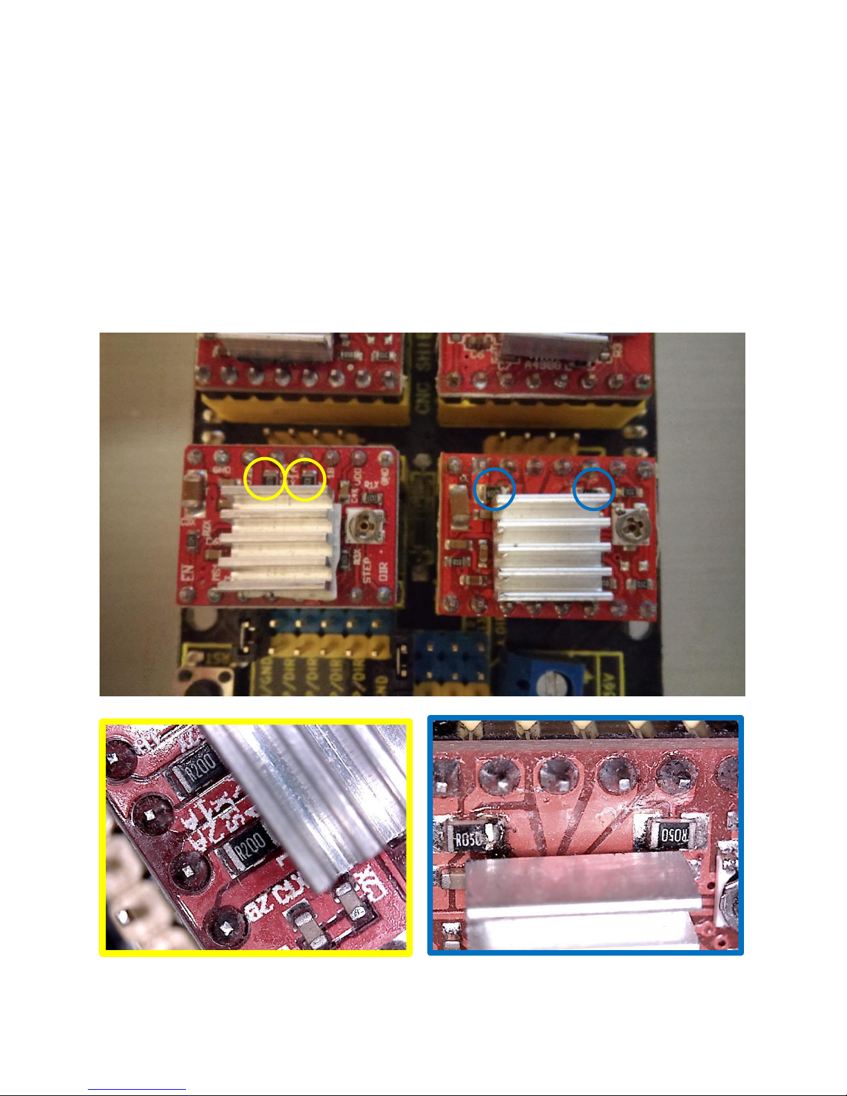
How do I change my current setting on the stepper motor drivers?
There are 2 styles of stepper drivers that we have for the E3. Both styles work equally well, but the
current needs to be set with different values. The yellow circles denote the driver with the R200
resistors. The blue circles are the R050 resistors. Note that these resistors are in different locations.

Setting the current on the A4899 stepper motor driver with a volt meter.
The current on the A4988 stepper drivers can be set easily with a volt-meter. The driver is setup to set a
reference voltage (volts) that determines the current (amps) to drive the stepper motors. First, we will
need to determine the correct current and resistor readings. The typical resistor values for the stepper
driver are 0.2, 0.1, 0.05 ohms, 2 of which are shown below.
Once we know the resistor value we can calculate the resistance we need by using the formula
𝑉𝑟𝑒𝑓 = 𝐼𝑚𝑎𝑥 ∗ 8 ∗ 𝑅 or 𝐼𝑚𝑎𝑥 = 𝑉𝑟𝑒𝑓/(8 ∗ 𝑅)
For the E3 CNC router we want the current to be around 0.9 amps. The settings would be as follows:
We can set the voltage by holding the negative led to ground and the positive lead to the potentiometer
as shown below. To turn the current up, turn clockwise. To turn the current down, turn counter

clockwise.
Setting the current on the A4899 stepper motor driver without a volt meter.
While a voltmeter will give you more accurate results. The drivers can be adjusted by turning them up or
down 1/8 of a turn and checking for proper movement after each setting.
Stepper motor current too low – The stepper motor is cool to the touch after it has been on for
a while. The stepper motor driver is not suppling enough current for the stepper motor to drive
axis. Turn up the stepper motor current on the A4988 driver.
Stepper motor current too high –The stepper motor is hot to the touch after it is been on for a
while. The stepper motor driver is heating up and going into protection mode. Once it cools it
turns back on. This can look like erratic stepper motor movement. Turn down the stepper
motor current on the A4988 driver.
The DeWalt motor shaft came out during assembly. (DeWalt brush
remove and replace)
If the shaft accidently fell out during assembly or you need to replace worn motor bushings these steps
will guide you thru the process of removing and replacing the motor’s brushes.

First you will need to remove the 4 screws to the top housing and remove the covers.
Use a small scewdriver to gently pull the brush springs out and lock them against the housing as shown.
Brush Spring

Remove the brush and repeat for the other side.
Brush Spring
Motor brush

Insert the DeWalt motor shaft.
Motor brush

Insert on screw to hold the shaft inplace.
Insert the motor brushes and place the brush spring as shown for both motor brushes.

Install the back cover and place components and wires as shown.

Insert the 4 screws.
Remove the mounting screw and carefully continue to install the DeWalt to the E3 router mount as
shown in the assembly manual.
 Loading...