

Page 1
INSTALLATION INSTRUCTIONS
TrimLine™ SURFACE-MOUNTED ADA DRYER
B-7120 White Painted Steel or B-7128 Stainless Steel
Patent Pending
Installation Instructions Surface-Mounted Hand Dryer ...............................................Pages 2 & 3
Form No. 712-69 Multi Language (Revised 8/09) © 2009 Bobrick Washroom Equipment, Inc.
Page 2
Electrical Characteristics
Model B-7120 White Painted Steel Cover and B-7128 Stainless Steel Cover, 115V AC, 15 Amp, 1725 Watts, 50/60 Hz, Single Phase, cULus listed.
Model B-7120 White Painted Steel Cover and B-7128 Stainless Steel Cover, 208–240V AC, 6.8-7.8 Amp, 1400-1900 Watts, 50/60 Hz, Single
Phase; cULus listed, VDE and CCC approved, and CE marked.
Installation instructions and template provide information that will assist in the installation of the Bobrick B-7120 and B-7128 115V, B-7120 and B-7128
208-240V. Retain Installation Instruction Sheet for important maintenance instructions and warranty information.
Recommended Mounting Heights
Distance from floor to bottom mounting screw holes of mounting base.
Children's Washrooms, ages 3-4 ..............................................................................................................................................36'' (915mm)
Children's Washrooms, ages 5-8 ..............................................................................................................................................40'' (1015mm)
Children's Washrooms, ages 9-12 ............................................................................................................................................44'' (1120mm)
Universal Design ......................................................................................................................................................................48'' (1219mm)
* Bobrick automatic hand dryers should be installed at least 15" (380mm) above any projection or horizontal surface which may interfere with the
operation of the automatic sensor.
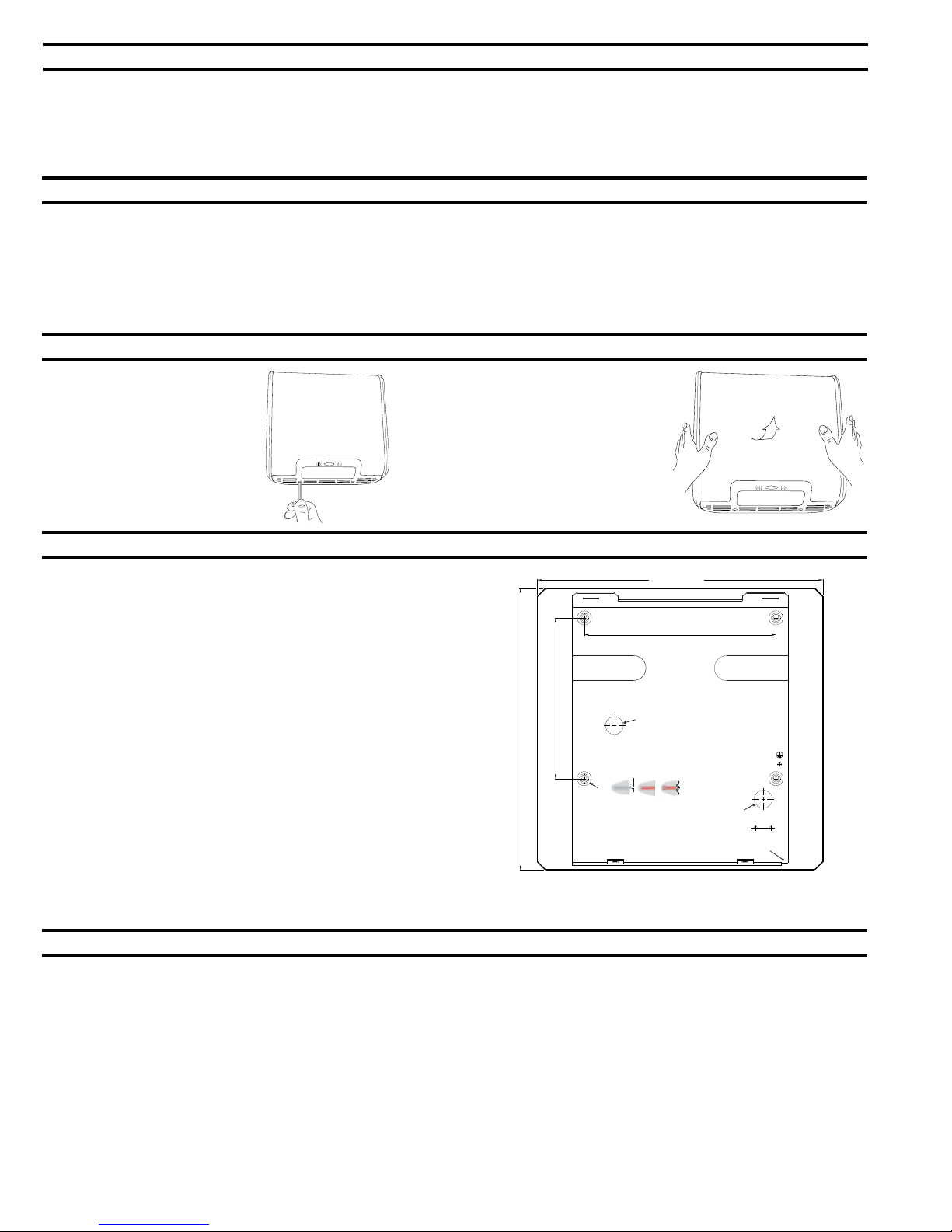
Removal of Cover
1. Start installation of dryer by
removing cover. Remove two
screws, from the bottom of the
dryer.
2. Rotate bottom of cover away
from mounting base and then lift
up.
Installation of Mounting Base
1. Hold the Installation Template against the wall in the desired location of
the installed dryer. See recommended mounting heights above.
2. Make sure line on template representing bottom of dryer mounting base
is horizontal and located at the desired height above floor.
3. Mark center of four mounting screw holes and hole for entry of electrical
wiring if electrical supply is concealed in wall and will enter dryer from
back through mounting base.
NOTE: Surface-mounted electrical supply entry is located in the lower right
corner of the mounting base. Surface-mounted supply cable should be
fitted in a conduit.
4. For brick, stone, and concrete walls drill four 0.315" (8mm) holes to suit
wall plugs 0.315" (8mm) x 1-1/4" (45mm) and screws#10 (4.8mm) x 2"
(50mm) long (provided). See template for wall plug and screw
installation details.
5. For plaster or dry wall construction, provide concealed backing to
comply with local building codes and secure with four #10 (M4.8) round head sheet-metal screws, or 3/16'' (5mm) toggle bolts (not furnished).
6. Fasten mounting base securely to wall.
7-3/4" 197mm
13-19/32" 345mm
x 4
WARNING: TURN ELECTRICAL POWER SUPPLY OFF BEFORE MAKING
ELECTRICAL CONNECTIONS.
DRYER MUST BE GROUNDED (EARTHED).
13-25/32" 350mm
Ø7/8" 22mm
Hole for between wall wiring
Ø 5/16" 8mm
1. 2. 3.
9-1/4" 235mm
Ø7/8" 22mm
Hole for between wall wiring
Flange cutout for
surface mounting
Electrical Connection
THIS DRYER IS INTENDED FOR CONNECTION TO FIXED WIRING.
FOR PROPER ELECTRICAL CONNECTIONS, INSTALLATION MUST CONFORM TO LOCAL BUILDING CODE (USA), IEE REGULATIONS (UK)
OR LOCAL REGULATION (OTHER COUNTRIES).
TURN ELECTRICAL POWER SUPPLY OFF BEFORE MAKING ELECTRICAL CONNECTIONS.
DRYER MUST BE GROUNDED (EARTHED).
UNIT MUST BE INSTALLED BY A QUALIFIED LICENSED ELECTRICIAN.
THIS APPLIANCE IS NOT TO BE USED FOR DOMESTIC PURPOSES BUT SOLELY IN COMMERCIAL PREMISES.
THIS APPLIANCE IS NOT INTENDED FOR USE BY PERSONS (INCLUDING CHILDREN) WITH REDUCED PHYSICAL, SENSORY OR MENTAL
CAPABILITIES, OR LACK OF EXPERIENCE AND KNOWLEDGE, UNLESS THEY HAVE BEEN GIVEN SUPERVISION OR INSTRUCTION
CONCERNING USE OF THE APPLIANCE BY A PERSON RESPONSIBLE FOR THEIR SAFETY.
CHILDREN SHOULD BE SUPERVISED TO ENSURE THAT THEY DO NOT PLAY WITH THE APPLIANCE
1. Check that the electrical rating shown on the Dryer (rating label) is compatible with the electrical supply.
2. Connect dryer to nearest distribution panel. Use wire as required by local electrical code. In the United States and Canada use #14 wire.
Page 2
Form No. 712-69 Multi Language (Revised 8/09) © 2009 Bobrick Washroom Equipment, Inc.
Page 3

Electrical Connection (cont.)
3. Wiring Instructions:
a) A fused means for disconnection in all poles must be provided in the fixed wiring in accordance with the wiring rules.
b) Trim insulation from end of electrical wire.
c) Remove screws in strain relief clamp. Lift clamping crossbar. Feed electrical wire through clamp.
d) Replace crossbar on strain relief clamp. Tighten screws securing electrical wire.
e) Make connection to terminal block as follows:
1) Connect the Live (Hot) wire to terminal marked L1 on terminal block.
2) Connect the Neutral wire to terminal marked L2 or N on terminal block
3) Connect Ground (Earth) wire to ground (earth) screw on baseplate marked
Replace Cover
1. Fit cover over mounting base.
NOTE: Four sides of cover overlap the
mounting base and should be flush with
the sides, top and bottom of the mounting base.
2. Replace and tighten two screws,
on the bottom to secure cover to
mounting base.
Check Dryer Operation
1. Turn electrical power supply on.
2. Position hands under air-outlet, within 4'' (100mm) of the bottom of the dryer.
3. Dryer should turn on. Warm air should blow from air-outlet. Drying time less than 25 seconds.
4. Remove hands from under air-outlet and dryer should stop (within 2 seconds).
Maintenance
WARNING: 1. TURN ELECTRICAL SUPPLY OFF BEFORE DOING ANY MAINTENANCE OR SERVICE TO DRYER.
2. CERTAIN INTERNAL PARTS ARE INTENTIONALLY NOT GROUNDED AND MAY PRESENT A RISK OF ELECTRIC
SHOCK ONLY DURING SERVICING. SERVICE PERSONNEL - DO NOT CONTACT THE FOLLOWING PARTS WHILE THE
APPLAINCE IS ENERGISED: - MOTOR LAMINATIONS.
3. DRYER MUST NOT BE OPERATED UNLESS COVER IS IN PLACE.
1. Exterior of cover should be cleaned with a damp cloth to remove dust and surface dirt. Do not use abrasive agents or solvents as they may
permanently damage surface of cover.
2. At least once every 6 months remove cover. Using a small brush or vacuum, clean out build up of dust and lint from air inlet/outlet grille, interior of
cover and around motor/fan housing.
NOTE: If dryer is installed where there is a lot of dust and dirt in the air, the interior of the dryer should be cleaned out more frequently.
Warranty
IMPORTANT LIMITED WARRANTY SAVE
Installation Date: _____________________________________________________________________________________________________________
Serial No(s).: _________________________________________________________________________________________________________________
Installation Address:___________________________________________________________________________________________________________
Telephone No.: _______________________________________________________________________________________________________________
The Bobrick B-7120 and B-7128 Dryer of the serial number(s) indicated herein, and all parts are warranted to the original owner of the installed unit for ten years
from date of original purchase against defects in factory workmanship or material under normal use and service
This warranty is limited to repair or exchange of defective parts at the option of Bobrick.
THIS WARRANTY DOES NOT COVER ACCIDENTAL DAMAGE, IMPROPER HANDLING OR INSTALLATION, OR REPAIRS MADE BY UNAUTHORIZED
PER SONS, AND SPECIFICALLY EXCLUDES CLAIMS FOR INDIRECT, ACCI DENTAL OR CONSEQUENTIAL DAMAGES TO PROPERTY. THE IMPLIED
WARRANTIES OF MERCHANTABILITY AND FITNESS FOR A PARTICULAR PURPOSE ARE LIMITED TO THE SAME DURATION OF THE ABOVE WARRANTY.
Some states do not allow the exclusion of incidental or consequential damages, so the above limitation or exclusion may not apply to you. Some states do not allow
limitations on how long an implied warranty lasts, so the above limitation may not apply to you. This warranty gives you specific legal rights, and you may also have
other rights which vary from state to state.
*
Normal service constitutes performing the following preventive maintenance procedure: Clean any lint, dust or grease from air-inlet and air-outlet grilles.
Labor costs for preventive maintenance shall be at owner's expense.
For repair or exchange of defective part, send the part together with installation date and serial number to BOBRICK.
*
.
Form No. 712-69 Multi Language (Revised 8/09) © 2009 Bobrick Washroom Equipment, Inc.
Page 3
Page 4

In the United States: BOBRICK WASHROOM EQUIPMENT, INC.
200 Commerce Drive, Clifton Park, NY 12065-1350, Telephone: (518) 877-7444, FAX: 518-877-5029
11611 Hart Street, North Hollywood, CA 91605-5882: (818) 982-9600, FAX: 818-503-1102
100 Bobrick Drive, Jackson, TN 38301-5625, Telephone: (731) 424-7000, FAX: 731-424-7800
In Canada: BOBRICK WASHROOM EQUIPMENT COMPANY
45 Rolark Drive, Scarborough, Ontario M1R 3B1, Telephone: (416) 298-1611, FAX: 416-298-6351
BOBRICK WASHROOM EQUIPMENT, INC. 11611 Hart Street, North Hollywood, CA 91605-5882: (818) 764-1000, FAX: 818-503-9941
BOBRICK WASHROOM EQUIPMENT Pty, Ltd. Australia +1 (818) 764-1000, FAX: +1 (818) 503-9941
BOBRICK WASHROOM EQUIPMENTLimited United Kingdom +44 (0)20 8366 1771, FAX: +44 (0)20 8363 5794
TrimLine™ Dryer is a trademark of Bobrick Washroom Equipment, Inc.
Form No. 712-69 Multi Language (Revised 8/09) © 2009 Bobrick Washroom Equipment, Inc.
www.bobrick.com
International:
 Loading...