

Page 1
INSTALLATION INSTRUCTIONS
B-710 COMPACDRYER™
SURFACE-MOUNTED AUTOMATIC HAND DRYER
Installation Instructions CompacDryer™ Surface-Mounted Hand Dryer ...................Pages 2 & 3
Instrucciones Para Instalación De Secadores De Manos Para Montar
Sobre Pared Bobrick CompacDryer™ ..........................................................................Pages 4 & 5
Einbauanleitung Bobrick CompacDryer™ Aufputzmontierte Händetrockerner ......Pages 6 & 7
Instructions Puor L’installation Bobrick CompacDryer™ Seches-Mains
En Applique ......................................................................................................................Pages 8 & 9
Istruzioni Per L’installazione Asciugamani Automatici A Parete
Bobrick CompacDryer™ ............................................................................................Pages 10 & 11
Page 2
7/8''
(22mm)
3-17/32''
(90mm)
3/4''
(18mm)
Entry Hole
for Between-Wall Wiring
5/8''
(16.5mm)
Entry Point
for Surface Mounted Wiring
8-3/32''
(205mm)
4-17/32''
(115mm)
Mounting Base
C
L
Horizontal
Reference
Horizontal
Reference
3-15/16''
(100mm)
7-7/8''
(200mm)
4-11/32''
(110mm)
Electrical Characteristics
Model B-710,115V AC, 15 Amp, 1725 Watts, 60 HZ, Single Phase, cULus listed.
Model B-710E, 220-240V, 7A, AC 1500-1700 Watts, 50/60 Hz, Single Phase; VDE approved, CE marked. B-710E is not available in the United
States and Canada.
Installation instructions and template provide information that will assist in the installation of the Bobrick B-710 115V, B-710E 220-240V. Retain
Installation Instruction Sheet for important maintenance instructions and warranty information.
Recommended Mounting Heights
Distance from floor to bottom mounting screw holes of mounting base.
Men's Washrooms ....................................................................................................................................................................46'' (1170mm)
Women's Washrooms ...............................................................................................................................................................44'' (1120mm)
Children's Washrooms, ages 3-9 .............................................................................................................................................32'' (815mm)
Children's Washrooms, ages 9-12 ............................................................................................................................................36'' (915mm)
Children's Washrooms, ages 12-15 ..........................................................................................................................................40'' (1015mm)
Children's Washrooms, ages 15-18 ..........................................................................................................................................44'' (1120mm)
Barrier-Free Design ..................................................................................................................................................................38'' (965mm)
* Bobrick automatic hand dryers should be installed 15" (380mm) above any projection or horizontal surface which may interfere with the
operation of the automatic sensor.
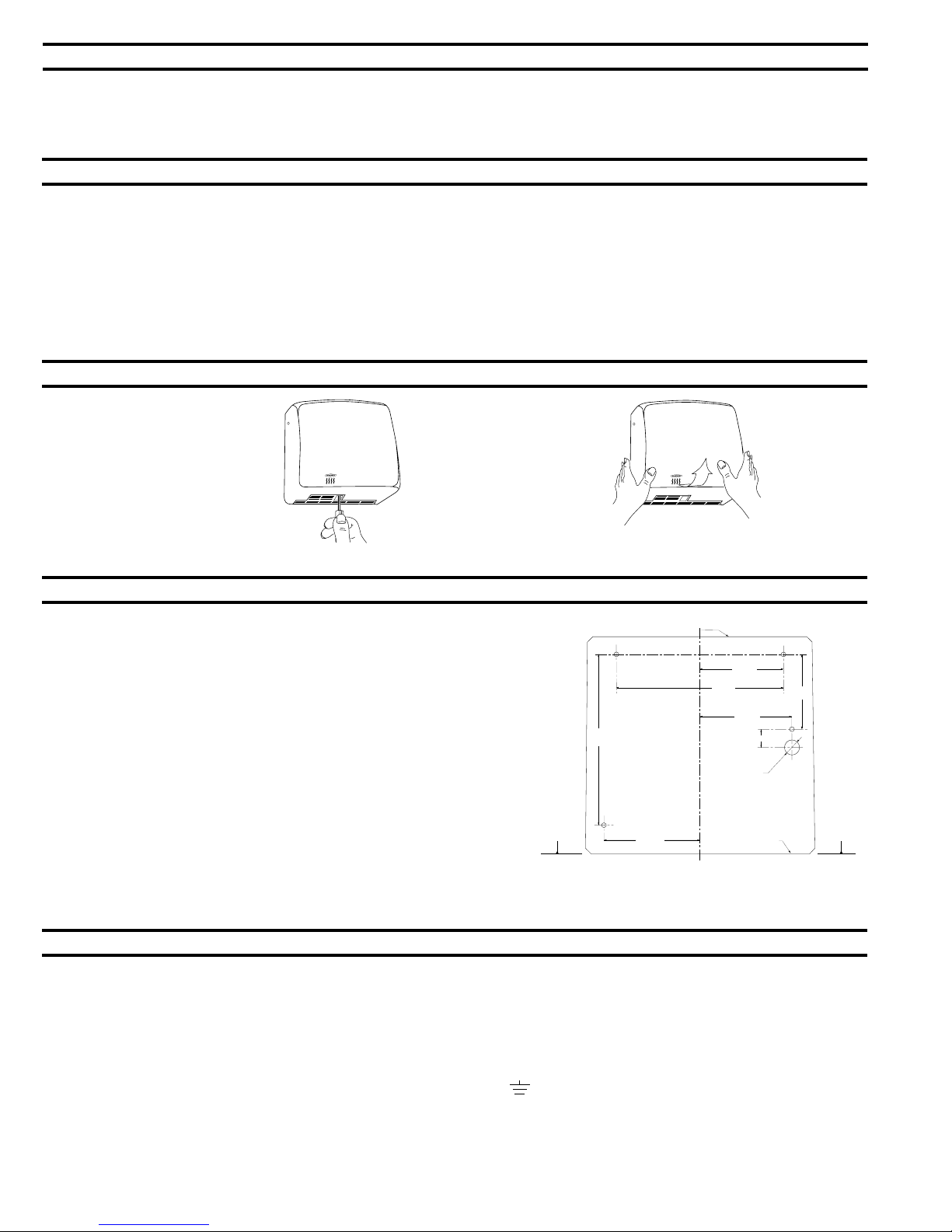
Removal of Cover
1. Start installation of dryer by
removing cover. Remove three
screws, one from each side and
one from the bottom of the
dryer. Lift the cover from the
mounting base.
Installation of Mounting Base
1. Hold the Installation Template against the wall in the desired location of the
installed dryer, see recommended mounting heights above.
2. Make sure line on template representing bottom of dryer mounting base is
horizontal and located at the desired height above floor.
3. Mark center of four mounting screw holes and hole for entry of electrical
wiring if electrical supply is concealed in wall and will enter dryer from back
through mounting base.
NOTE: Surface-mounted electrical supply entry is located in the lower right corner
of the mounting base. Bottom of mounting base has 1/2'' square (13mm) opening in
lower right corner to accommodate connection of electrical conduit.
4. Drill four holes for #10 (M4.8) mounting bolts or screws (not furnished).
5. For masonry walls provide four #10 expansion shields or anchors and secure
with four #10 (M4.8) sheet-metal screws (not furnished). For plaster or dry
wall construction, provide concealed backing to comply with local building
codes and secure with four #10 (M4.8) round-head sheet-metal screws, or
3/16'' (5mm) toggle bolts (not furnished).
NOTE: Use 2'' (50mm) long screws in top two mounting holes. Use 3'' (75mm) long
screws in lower two mounting holes.
6. Fasten mounting base securely to wall.
WARNING: TURN ELECTRICAL POWER SUPPLY OFF BEFORE
MAKING ELECTRICAL CONNECTIONS. DRYER MUST BE
GROUNDED (EARTHED).
Electrical Connection
FOR PROPER ELECTRICAL CONNECTIONS, CHECK LOCAL BUILDING CODE. UNIT MUST BE INSTALLED BY A QUALIFIED LICENSED
ELECTRICIAN. WARNING: TURN ELECTRICAL POWER SUPPLY OFF BEFORE MAKING ELECTRICAL CONNEC TIONS.
1. Connect dryer to nearest distribution panel. Use wire as required by local electrical code. In the United States and Canada use #12 wire.
2. Wiring Instructions:
a) A fused means for disconnection in all poles must be provided in the fixed wiring in accordance with the wiring rules.
b) Trim insulation from end of electrical wire.
c) Remove screws in strain relief clamp. Remove clamping crossbar. Feed electrical wire through clamp.
d) Make connection to terminal block as follows:
1) 115V: Connect ground (earthed) wire to ground (earthed) terminal marked . 220-240V Dryers are doubled insulated and should not be
fitted with an earth (ground) wire.
2) Connect the black or Hot wire to terminal marked L1.
3) Connect the white or neutral wire to terminal marked N.
e) Replace crossbar on strain relief clamp. Tighten screws securing electrical wire.
NOTE: DEDICATED LINE IS REQUIRED FOR EACH 115 VOLT DRYER.
Page 2
Page 3
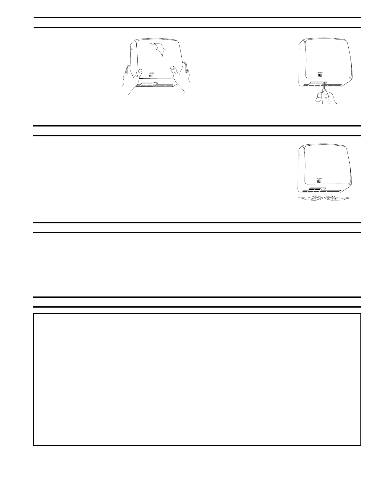
Replace Cover
1. Fit cover over mounting base.
NOTE: Four sides of cover overlap the
mounting base and should be flush with
the sides, top and bottom of the mounting base.
2. Replace and tighten three
screws, one on each side and
one on the bottom to secure
cover to mounting base.
Check Dryer Operation
1. Turn electrical power supply on.
2. Position hands under air-outlet, within 4'' (100mm) of the bottom of the dryer.
3. Dryer should turn on. Warm air should blow from air-outlet.
4. Remove hands from under air-outlet and dryer should stop (within 2 seconds).
Maintenance
WARNING: 1. TURN ELECTRICAL SUPPLY OFF BEFORE DOING ANY MAINTENANCE OR SERVICE TO DRYER.
2. DRYER MUST NOT BE OPERATED UNLESS COVER IS IN PLACE.
1. Exterior of cover should be cleaned with a damp cloth to remove dust and surface dirt. Do not use abrasive agents or solvents as they may
permanently damage surface of cover.
2. At least once every 12 months remove cover. Using a small brush or vacuum, clean out build up of dust and lint from air inlet/outlet grille, interior of
cover and around motor/fan housing.
NOTE: If dryer is installed where there is a lot of dust and dirt in the air, the interior of the dryer should be cleaned out more frequently.
Warranty
IMPORTANT LIMITED WARRANTY SAVE
Installation Date: _____________________________________________________________________________________________________________
Serial No(s).: _________________________________________________________________________________________________________________
Installation Address:___________________________________________________________________________________________________________
Telephone No.: _______________________________________________________________________________________________________________
The Bobrick B-710 CompacDryer™ of the serial number(s) indicated herein, and all parts are warranted to the original owner of the installed unit for five years from
date of original purchase against defects in factory workmanship or material under normal use and service
This warranty is limited to repair or exchange of defective parts at the option of Bobrick.
THIS WARRANTY DOES NOT COVER ACCIDENTAL DAMAGE, IMPROPER HANDLING OR INSTALLATION, OR REPAIRS MADE BY UNAUTHORIZED
PER SONS, AND SPECIFICALLY EXCLUDES CLAIMS FOR INDIRECT, ACCI DENTAL OR CONSEQUENTIAL DAMAGES TO PROPERTY. THE IMPLIED
WARRANTIES OF MERCHANTABILITY AND FITNESS FOR A PARTICULAR PURPOSE ARE LIMITED TO THE SAME DURATION OF THE ABOVE WAR RANTY.
Some states do not allow the exclusion of incidental or consequential damages, so the above limitation or exclusion may not apply to you. Some states do not allow
limitations on how long an implied warranty lasts, so the above limitation may not apply to you. This warranty gives you specific legal rights, and you may also have
other rights which vary from state to state.
*
Normal service constitutes performing the following preventive maintenance procedure: Clean any lint, dust or grease from air-inlet and air-outlet grilles.
Labor costs for preventive maintenance shall be at owner's expense.
For repair or exchange of defective part, send the part together with installation date and serial number to BOBRICK.
*
.
Page 3
Page 4
7/8''
(22mm)
3-17/32''
(90mm)
3/4''
(18mm)
Entry Hole
for Between-Wall Wiring
5/8''
(16.5mm)
Entry Point
for Surface Mounted Wiring
8-3/32''
(205mm)
4-17/32''
(115mm)
Mounting Base
C
L
Horizontal
Reference
Horizontal
Reference
3-15/16''
(100mm)
7-7/8''
(200mm)
4-11/32''
(110mm)
Características Eléctricas
Modelo B-710, 115V CA, 15 A, 1725 W, 60 Hz, Monofásico, Clasificado cULus.
Modelo B-710E, 220-240V CA, 7 A, 1500-1700 W, 50/60 Hz, Monofásico, Aprobado VDE y marcado CE.
B-710E no está disponible en los Estados Unidos y Canadá.
Las instrucciones y el patrón proporcionan información que ayudan a instalar los Secadores Bobrick B-710 115V, B-710E 220-240V. Retenga la hoja
de instrucciones de instalación para instrucciones importantes, sobre mantenimiento e información sobre la garantía.
Alturas de Montaje Recomendadas
Distancia del suelo a los agujeros para tornillos de montaje inferiores de la base de montaje
Aseos para caballeros ..............................................................................................................................................................1170mm (46'')
Aseos para señoras ..................................................................................................................................................................1120mm (44'')
Aseos para niños, de 3 a 9 años ..............................................................................................................................................815mm (32'')
Aseos para niños, de 9 a 12 años ............................................................................................................................................915mm (36'')
Aseos para niños, de 12 a 15 años ..........................................................................................................................................1015mm (40'')
Aseos para niños, de 15 a 18 años ..........................................................................................................................................1120mm (44'')
Aseos para minusválidos ..........................................................................................................................................................965mm (38'')
* Los secadores de manos automáticos de Bobrick se deben instalar a 380mm (15") por encima de cualquier saliente o superficie horizontal
que pueda interferir con la operación del sensor automático.
Cómo Quitar La Cubierta Del Secador
1. Comenzar la instalación del
secador quitando la cubierta.
Retirar los tres tornillos, uno en
la parte inferior y uno de cada
lado del secador. Separar la
cubierta de la base de montaje.
Instalación De La Base De Montaje
1. Retener el patrón de Instalación (véase la otra cara de la hoja de instrucciones)
contra la pared en la posición deseada del secador instalado, véanse las
siguientes alturas de montaje recomendadas.
2. Asegure que la línea en el patrón que representa la parte inferior de la base de
montaje del secador está a nivel horizontal y situada a la altura deseada al suelo.
3. Marcar el centro de los cuatro agujeros de montaje con tornillos y del agujero de
entrada del cableado eléctrico si la alimentación está oculta en la pared y
entra el secador atrás por la base de montaje.
NOTA: La entrada de la alimentación de red montada en la superficie está situada
en la base de montaje en su esquina derecha inferior. La parte inferior de la base de
montaje tiene un agujero cuadrado de 13 mm (1/2'') en su esquina derecha inferior
para acomodar la conexión del conducto eléctrico.
4. Perforar cuatro agujeros para pernos o tornillos de montaje, de diámetro #10
(M4.8) (no provistos por Bobrick).
5. En el caso de paredes de albañilería, usar tres escudos ensanchadores o
fijadores tamaño #10, y fijar con cuatro tornillos #10 (M4.8) para chapa (no
provistos). En construcciones secas (huecas) o escayoladas, usar una placa
interna que conforma con los códigos de construcción locales y fijar con cuatro
tornillos tamaño #10 (M4.8) de cabeza redonda para chapa o usar pernos
fijadores de palanca 5 mm (3/16'') (no provistos).
NOTA: Usar dos tornillos de 50 mm (2'') de largo en los dos agujeros superiores. Usar
dos tornillos de 75 mm (3'') de largo en los dos agujeros inferiores.
ADVERTENCIA: DESCONECTAR LA ALIMENTACIÓN DE
RED ANTES DE HACER LAS CONEXIONES ELÉCTRICAS.
EL SECADOR TIENE QUE ESTAR CONECTADO A TIERRA.
6. Fijar la base firmemente sobre la pared.
Conexión Eléctrica
PARA TENER LAS CONEXIONES ELÉCTRICAS CORRECTAS, CONSULTE EL CÓDIGO DE CONSTRUCCIÓN LOCAL. LA UNIDAD LA DEBE
INSTALAR UN ELECTRICISTA CAPACITADO CALIFICADO.
1. Conectar el secador al tablero de distribución más cercano. Usar el tipo de cable exigido por el código eléctrico local. En los Estados Unidos
y Canadá, usar alambre #12.
2. Instrucciones de cableado
a) El cableado fijo debe incorporar un dispositivo interruptor de fusibles, para desconexión de todos los polos, según las normas de cableado.
b) Eliminar el aislamiento en el extremo del cable.
c) Retirar los tornillos de la abrazadera aliviadora de tensión. Retirar la barra transversal de sujeción. Alimentar el cable por la abrazadera.
d) Efectúe la conexión al bloque de bornes de la manera siguiente:
1) 115V: Conectar el conductor de tierra al borne de tierra marcado . Los secadores de 220-240V tienen aislamiento doble y no necesitan
una conexión a tierra.
2) Conectar el conductor negro o a Tensión al borne marcado L1.
3) Conectar el conductor blanco o neutro al borne marcado N
e) Reponer la barra transversal en la abrazadera de alivio de tensión. Apretar los tornillas para sujetar el cable.
NOTA: ES NECESARI UNA LÍNEA DEDICADA PARA CADA SECADOR DE 115 VOLTIOS.
Page 4
Page 5

Restitución De La Cubierta
1. Instalar la cubierta sobre la base
de montaje.
NOTA: Los cuatro lados de la cubierta
solapan la base de montaje y deben
estar a ras con los cuatro lados de la
base de montaje.
2. Reponer y apretar los tres
tornillos, uno en cada lado y
uno en la parte inferior para fijar
la cubierta sobre la base de
montaje..
Verificación De La Operación Del Secador
1. Conectar la tensión eléctrica
2. Situar las manos debajo de la salida de aire, a 100 mm (4'') de la parte inferior del secador
3. El secador debe encenderse. Saldrá aire caliente de la salida de aire.
4. Retirar las manos de la salida de aire y el secador debe pararse (después de 2 segundos).
Mantenimiento
ADVERTENCIA: 1. DESCONECTAR LA ALIMENTACIÓN DE RED ANTES DE HACER CUALQUIER TRABAJO DE REVISIÓN O
MANTENIMIENTO DEL SECADOR.
2. NO OPERAR EL SECADOR SIN TENER LA CUBIERTA INSTALADA.
1. Se debe limpiar la cubierta con un paño húmedo para quitar cualquier polvo o suciedad. No usar agentes abrasivos ni solventes porque pueden
dañar permanentemente a la superficie de la cubierta.
2. Al menos cada 12 meses, quitar la tapa y limpiar el secador con un cepillo pequeño o un aspirador, eliminar cualquier acumulación de polvo
en la rejilla de salida/ entrada de aire a cubierta interior y alrededor del alojamiento del motor y ventilador. NOTA: Si se ha instalado el secador
en un sitio de mucho polvo y suciedad en el aire, se debe limpiar el interior del secador con mayor frecuencia.
Garantía
LIMITADA IMPORTANTE - COMPLETAR GUARDAR
La fecha de instalación: ___________________________________________________________________________________________________________
No(s). de serie: ___________________________________________________________________________________________________________________
Dirección de la instalación: _________________________________________________________________________________________________________
No. de teléfono: ___________________________________________________________________________________________________________________
El/Los secador/es Bobrick B-710 CompacDryer™ con el/los número/s de serie indicado/s aquí, y todas las piezas (excepto las escobillas del motor) están
garantizados al propietario original de compra, por cinco años, contra los defectos de mano de obra en fábrica o de materiales, bajo uso y servicio normales. *
Esta garantía está limitada a la reparación o cambio de piezas defectuosas a la discreción de Bobrick Washroom Equipment, Inc.
ESTA GARANTÍA NO CUBRE DAÑOS ACCIDENTALES, EL MANEJO O INSTALACIÓN INADECUADAS NI REPARACIONES POR PERSONAS NO
AUTORIZADAS, Y EXCLUYE ESPECÍFICAMENTE CUALESQUIER RECLAMO POR DAÑOS INDIRECTOS, ACCIDENTALES O CONSECUENCIALES
A PROPIEDAD. SE LIMITAN LAS GARANTÍAS IMPLÍCITAS DE COMERCIALIBILIDAD Y APTITUD PARA UN PROPÓSITO ESPECÍFICO A LA MISMA
DURACIÓN QUE LA SUSODICHA GARANTÍA.
Algunos estados no permiten la exclusión de compensaciones incidentales o consecuenciales, así que la susodicha limitación quizás no le sea aplicable. Esta
garantía le otorga ciertos derechos legales específicos, y posiblemente tiene otros derechos que pueden variar entre estados.
* El servicio normal consiste en realizar los siguientes procedimientos de mantenimiento preventivo: Quitar la cubierta y eliminar cualesquier fibra, polvo
o grasa de la rejilla de entrada/ salida de aire.
Los gastos de mano de obra del mantenimiento preventivo correrán a cargo del propietario.
Para reparar o cambiar una pieza defectuosa, sírvase enviar la pieza con su fecha de instalación y número de serie a BOBRICK.
Page 5
Page 6

7/8''
(22mm)
3-17/32''
(90mm)
3/4''
(18mm)
Entry Hole
for Between-Wall Wiring
5/8''
(16.5mm)
Entry Point
for Surface Mounted Wiring
8-3/32''
(205mm)
4-17/32''
(115mm)
Mounting Base
C
L
Horizontal
Reference
Horizontal
Reference
3-15/16''
(100mm)
7-7/8''
(200mm)
4-11/32''
(110mm)
Elektrische Daten
Modell B-710, 115V WS, 15 A, 1725 W, 60 Hz, einphasig cULus-geprüft.
Modell B-710E, 220-240V WS, 7 A, 1500-1700 W, 50/60 Hz, einphasig, VDE-geprüft, tragen das CE-Kennzeichen.
B-710E ist in den Vereinigten Staaten und Kanada nicht erhältlich.
Einbauanleitung und Schablone enthalten Informationen, die beim Einbau der Bobrick-Modelle B-710 115 V, B-710E 220-240 V nützlich sind.
Bewahren Sie die Einbauanleitung zur Einsichtnahme der wichtigen Wartungsanweisungen und Garantieinformationen auf.
Empfohlene Einbauhöhen
Abstand zwischen Boden und unteren Löchern für Befestigungsschrauben an der Grundplatte.
Waschräume (Männer) .............................................................................................................................................................1170mm (46'')
Waschräume (Frauen) ..............................................................................................................................................................1120mm (44'')
Waschräume (Kinder von 3-9 Jahren) ......................................................................................................................................815mm (32'')
Waschräume (Kinder von 9-12 Jahren) ....................................................................................................................................915mm (36'')
Waschräume (Kinder von 12-15 Jahren) ..................................................................................................................................1015mm (40'')
Waschräume (Kinder von 15-18 Jahren) ..................................................................................................................................1120mm (44'')
Für Behinderte ..........................................................................................................................................................................965mm (38'')
* Um jegliche Stoerung der Operation des Trockners zu vermeiden, Bobrick's automatische Haende Trockner solte auf einer Hoehe von 380mm
(15") ueber einen Wandvorbau oder einer horizontale Flaeche montiert werden.
Entfernen Des Gehäuses
1. Beginnen Sie mit dem Einbau
des Trockners, indem Sie das
Gehäuse entfernen. Entfernen
Sie drei Schrauben, d. h. eine
von jeder Seite und eine vom
Unterteil des Trockners. Heben
Sie das Gehäuse von der
Grundplatte weg.
Einbau Der Grundplatte
1. Halten Sie die Einbauschablone (siehe andere Seite der Anweisungen) an der
gewünschten Position des eingebauten Trockners an die Wand und beachten Sie
dabei die folgenden empfohlenen Einbauhöhen.
2. Stellen Sie sicher, dass die Linie an der Schablone, die den unteren Teil der
Grundplatte des Trockners darstellt, waagrecht ist und sich auf der gewünschten
Höhe über dem Boden befindet.
3. Markieren Sie die Mitte der vier Löcher für die Befestigungsschrauben und des
Lochs für den Eingang der elektrischen Verdrahtung, falls die Stromversorgung in der
Mauer unter Putz ist und von hinten durch die Grundplatte in den Trockner eingeht.
HINWEIS: Der Eingang der Stromversorgung bei Modellen für Wandeinbau befindet sich
in der rechten unteren Ecke der Grundplatte. Im Boden der Grundplatte ist in der rechten
unteren Ecke eine 13 mm große viereckige Öffnung für den Anschluss des Isolierrohrs.
4. Bohren Sie vier Löcher für Befestigungsschrauben #10 (M4.8) Durchmesser (nicht
von Bobrick geliefert).
5. Für Mauerwerk stellen Sie vier Spreizdübel #10 bereit, die dann mit vier
Blechschrauben #10 (M4.8) befestigt werden (nicht geliefert). Für Wandputz oder
Wandkonstruktion aus Trockenbauplatten stellen Sie eine Rückwand im Unterputz
bereit, um die örtlichen Bauvorschriften zu erfüllen, und befestigen diese mit vier
Halbrundblechschrauben #10 (M4.8) oder Knebelschrauben 5 mm (nicht geliefert).
HINWEIS: Verwenden Sie 50 mm lange Schrauben in den beiden oberen und 75 mm
lange Schrauben in den beiden unteren Befestigungslöchern.
6. Befestigen Sie die Grundplatte sicher an der Wand.
WARNHINWEIS: VOR DEM HERSTELLEN
DER ELEKTRISCHEN ANSCHLÜSSE IST DIE
STROMVERSORGUNG ABZUSCHALTEN.
DER TROCKNER MUSS GEERDET SEIN.
Elektrischer Anschluss
FÜR EINEN ORDNUNGSGEMÄSSEN ELEKTRISCHEN ANSCHLUSS SEHEN SIE BITTE DIE ÖRTLICHEN BAUVORSCHRIFTEN EIN. DAS GERÄT MUSS
VON EINEM QUALIFIZIERTEN UND DAZU BEFÄHIGTEN ELEKTRIKER EINGEBAUT WERDEN.
1. Schließen Sie den Trockner an der nächstgelegenen Verteilertafel an. Verwenden Sie die Drähte den örtlichen Vorschriften entsprechend. In den USA und
Kanada verwenden Sie Draht #12.
2. Verdrahtungsanleitung
a) Eine mit Sicherung versehene Vorrichtung zur Unterbrechung an allen Polen muss in der Festverdrahtung den Verdrahtungsvorschriften entsprechend
angebracht sein.
b) Entfernen Sie die Isolierung vom Ende des Drahts.
c) Entfernen Sie die Schrauben von der Zugentlastungsklemme. Entfernen Sie den Anpressbalken und führen Sie den Draht durch die Klemme.
d) Stellen Sie den Anschluss an der Reihenklemme wie folgt her:
1) 115V: Schließen Sie den Erdungsdraht an der Erdanschlussklemme mit der Markierung an. Trockner mit 220-240V sind zweifach isoliert und dürften
mit keinem Erdungsdraht ausgestattet sein.
2) Bringen Sie den schwarzen bzw. stromführenden Draht an der mit L1 markierten Klemme an.
3) Bringen Sie den weißen Draht bzw. Nullleiter an der mit N markierten Klemme an.
e) Bringen Sie den Anpressbalken wieder an der Zugentlastungsklemme an. Ziehen Sie zur sicheren Befestigung des Drahts die Schrauben an.
HINWEIS: FÜR JEDEN TROCKNER MIT 115 VOLT IST EINE SPEZIELLE LEITUNG ERFORDERLICH.
Page 6
Page 7

Erneutes Anbringen Des Gehäuses
1. Bringen Sie das Gehäuse über der
Grundplatte an.
HINWEIS: Die vier Seiten des
Gehäuses gehen über die Grundplatte
hinaus und müssen mit den Seiten
sowie dem oberen und unteren Teil der
Grundplatte bündig sein.
2. Bringen Sie die drei Schrauben,
d. h. eine auf jeder Seite und
eine unten, wieder an, um das
Gehäuse sicher an der
Grundplatte zu befestigen.
Prüfen Des Trocknerbetriebs
1. Schalten Sie den Strom ein.
2. Halten Sie die Hände unter die Luftauslassöffnung innerhalb von 100 mm vom Unterteil des Trockners.
3. Der Trockner müsste sich nun einschalten und warme Luft durch die Luftauslassöffnung strömen.
4. Entfernen Sie die Hände von der Luftauslassöffnung, was ein Ausschalten des Trockners bewirken müsste
(innerhalb von 2 Sekunden).
Wartung
WARNHINWEIS: SCHALTEN SIE DIE STROMVERSORGUNG AUS, BEVOR IRGENDWELCHE WARTUNGS- ODER
INSTANDHALTUNGSARBEITEN AM TROCKNER AUSGEFÜHRT WERDEN. DER TROCKNER DARF NUR BEI ANGEBRACHTEM GEHÄUSE
BETRIEBEN WERDEN.
1. Das Äußere des Gehäuses muss mit einem feuchten Tuch abgewischt werden, um Staub und Oberflächenschmutz zu entfernen. Verwenden
Sie keine Scheuermittel oder Lösungsmittel, da sie die Gehäuseoberfläche permanent beschädigen könnten.
2. Nehmen Sie das Gehäuse mindestens alle 12 Monate einmal ab. Entfernen Sie mit einer kleinen Bürste oder einem kleinen Staubsauger eine
Ansammlung von Staub oder Fussel vom Lufteinlass-/-auslassgitter, von der Innenseite des Gehäuses und von der Motor-/Gebläseeinfassung.
HINWEIS: Wenn ein Trockner an einem Ort mit viel Staub und Schmutz in der Luft installiert ist, muss das Innere des Trockners häufiger gereinigt
werden.
Warranty
WICHTIG BESCHRÄNKE GARANTIE AUFHEBEN
Installationsdatum: ________________________________________________________________________________________________________________
Seriennummer(n).: ________________________________________________________________________________________________________________
Standort (Adresse): _______________________________________________________________________________________________________________
Telefonnummer: __________________________________________________________________________________________________________________
Bobrick bietet dem Erstkäufer der installierten Einheit des Bobrick CompacDryer™-Trockners B-710 mit der o. a. Seriennummer und aller Teile eine 5jährige Garantie
ab dem ursprünglichen Erweb für Material- und Fertigungsfehler bei normalem Einsatz und Betrieb. *
Die Garantie ist auf Reparatur oder Ersatz der fehlerhaften Teile im Ermessen von Bobrick beschränkt.
DIE GARANTIE DECKT KEINE UNFALLSCHÄDEN, UNSACHGEMÄSSE VERWENDUNG ODER INSTALLATION, ODER VON UNBEFUGTEN PERSONEN
DURCHGEFÜHRTE REPARATUREN, UND SCHLIESST INSBESONDERE ANSPRÜCHE FÜR MITTELBARE, UNFALL- ODER FOLGESCHÄDEN VON
GEGENSTÄNDEN AUS. DIE IMPLIZIERTEN GARANTIEN VON HANDELSFÄHIGKEIT UND EIGNUNG FÜR EINEN BESTIMMTEN ZWECK SIND AUF
DENSELBEN ZEITRAUM WIE DIE O. A. GARANTIE BESCHRÄNKT.
Einige Staaten lassen den Ausschluss von mittelbaren oder Folgeschäden nicht zu, weshalb sich die o. a. Beschränkung bzw. der Ausschluss evtl. nicht auf Sie
bezieht. Einige Staaten lassen keine Beschränkung über die Dauer einer implizierten Garantie zu, weshalb sich die o. a. Beschränkung evtl. nicht auf Sie bezieht.
Diese Garantie bietet Ihnen spezielle gesetzliche Rechte und Sie haben evtl. auch andere Rechte, die von Staat zu Staat unterschiedlich sind.
* Ein normaler Betrieb bedeutet die Durchführung der folgenden vorbeugenden Wartungsarbeiten: Entfernen Sie Fussel, Staub und Schmiere vom
Lufteinlass-/-auslassgitter.
Die Lohnkosten für die vorbeugende Wartung müssen vom Besitzer getragen werden.
Zur Reparatur oder zum Ersatz des fehlerhaften Teils senden Sie dieses unter Angabe des Installationsdatums und der Seriennummer an BOBRICK zurück.
Page 7
Page 8

7/8''
(22mm)
3-17/32''
(90mm)
3/4''
(18mm)
Entry Hole
for Between-Wall Wiring
5/8''
(16.5mm)
Entry Point
for Surface Mounted Wiring
8-3/32''
(205mm)
4-17/32''
(115mm)
Mounting Base
C
L
Horizontal
Reference
Horizontal
Reference
3-15/16''
(100mm)
7-7/8''
(200mm)
4-11/32''
(110mm)
Caractéristiques Électriques
Modèle B-710, 115 V c.a., 15 A, 1725 W, 60 Hz, monophasé, homologué cULus.
Modèle B-710E, 220–240V AC, 7A, 1500-1700 W, 50/60Hz, monophasé; agréé VDE, marquage CE.
B-710E n’est pas disponible aux États-Unis et au Canada.
La notice et le gabarit d’installation donnent des informations destinées à faciliter l’installation des sèche-mains Bobrick B-710 115 V, B-710E 220-240
V. Conserver la notice d’installation afin de pouvoir se référer aux instructions importantes concernant l’entretien et les informations sur la garantie.
Hauteurs de Montage Recommandées
Distance du sol au bas des trous à vis de montage du socle
Cabinet de toilette hommes ......................................................................................................................................................1170mm (46'')
Cabinet de toilette femmes ......................................................................................................................................................1120mm (44'')
Cabinet de toilette enfants, âges 3-9 ........................................................................................................................................815mm (32'')
Cabinet de toilette enfants, âges 9-12 ......................................................................................................................................915mm (36'')
Cabinet de toilette enfants, âges 12-15 ....................................................................................................................................1015mm (40'')
Cabinet de toilette enfants, âges 15-18 ....................................................................................................................................1200mm (44'')
Pour les handicapés .................................................................................................................................................................965mm (38'')
* Pour l'installation il est necessaire de respecter une distance minimale de 380mm (15") au dessous du sèche-mains automatique, pour
empécher une d'eclanchement permanant.
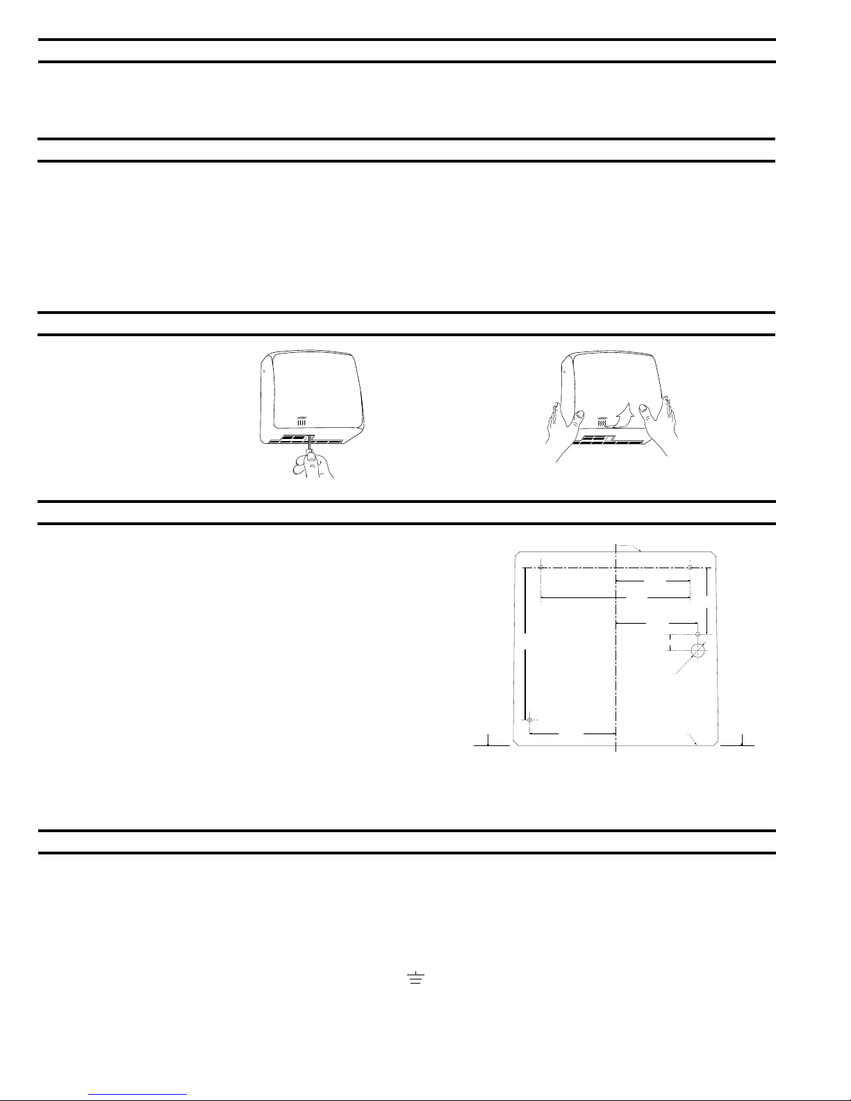
Retrait Du Couvercle
1. Commencer l’installation du
sèche-mains en retirant le
couvercle. Retirer les trois vis,
l’une de chaque côte et une sur l
la partie inférieure du sèche mains. Soulever le couvercle
pour l’extraire du socle.
Installation Du Socle
1. Placer le gabarit d’installation (voir le verso de la fiche technique) sur le mur à
l’endroit voulu pour l’installation du sèche-mains. Voir le tableau des hauteurs de
montage recommandées.
2. Vérifier que la ligne du gabarit représentant la partie inférieure du socle du sèche-
mains est horizontale, et qu’elle est située à la hauteur voulue au-dessus du sol.
3. Marquer le milieu des quatre trous prévus pour les vis de montage, et le milieu de
l’orifice d’entrée du câble électrique (s’il faut dissimuler le câble électrique dans le
mur). Ce câble entrera dans le sèche-mains par l’arrière, à travers le socle de
montage.
NOTA : L’entrée prévue pour le câble électrique monté en surface est située dans le coin
en bas à droite du socle. La base du socle comprend un orifice carré de 13 mm de côté
(1/2'') dans le coin en bas à droite prévu pour recevoir la connexion du conduit électrique.
4. Percer quatre trous pour des boulons ou des vis de fixation N° 10 (M4.8) (non
fournis).
5. Pour les murs en maçonnerie, prévoir quatre écrans ou ancrages N° 10, puis fixer
avec quatre vis à tôle N°10 (M4.8) (non fournies). Pour les murs en plâtre ou
maçonnerie sèche, prévoir un renforcement dissimulé conforme aux codes locaux
de construction et fixer avec quatre vis à tôle à tête ronde N° 10 (M4.8), ou cinq
boulons articulés de 5 mm (non fournis).
NOTA : Utiliser des vis de 50 mm de long dans les deux trous de montage supérieurs.
Utiliser des vis de 75 mm de long dans les deux trous de montage inférieurs.
6. Bien fixer le socle au mur.
AVERTISSEMENT: AVANT D’EFFECTUER TOUT
RACCORDEMENT ÉLECTRIQUE, COUPER L’ALIMENTATION
ÉLECTRIQUE.
Raccordement Electrique
POUR EFFECTUER UN RACCORDEMENT ÉLECTRIQUE CORRECT, VÉRIFIER LE CODE LOCAL DE CONSTRUCTION. IL EST IMPÉRATIV DE FAIRE
INSTALLER CET APPAREIL PAR UN ÉLECTRICIEN QUALIFIÉ COMPÉTENT.
1. Brancher le sèche-mains au tableau de distribution le plus proche. Utiliser le câble exigé
par le code local d’électricité. Aux États-Unis et au Canada, utiliser un câble N° 12.
2. Instructions de câblage:
a) ll faut prévoir un dispositif à fusible pour déconnexion dans tous les pôles, incorporé dans le câblage fixe conformément aux réglements d'installation.
b) Dégager la gaine d’isolation du câble électrique.
c) Retirer la vis de la pince de décharge des contraintes. Retirer la barre de serrage transversale. Faire passer le câble électrique à travers la pince.
d) Pour effectuer le raccordement à la boîte de jonction, procéder comme suit:
1) Sèche-mains de 115 V: Raccorder le câble de masse (mise à la terre) à la borne de masse marquée , Les sèche- mains de 220-240 V ont
une double isolation et ne doivent pas être munis d’un câble de masse (mise à la terre).
2) Raccorder le conducteur noir (Sous tension) à la borne marquée L1.
3) Raccorder le conducteur blanc (Neutre) à la borne marquée N.
e) Remettre la barre transversale sur la pince de décharge des contraintes. Serrer les vis afin de fixer le câble électrique.
NOTA : UN CÂBLE SPÉCIAL EST NÉCESSAIRE POUR CHAQUE SÈCHE-MAINS DE 115 V.
Page 8
Page 9

Remettre Le Couvercle
1. Placer le couvercle sur le socle.
NOTA: Les quatre côtés du couvercle
recouvrent le socle et doivent être à ras
des côtés, et de la partie supérieure et
inférieure du socle.
2. Faire pivoter le couvercle sur la
partie avant du socle.
3. Remettre les trois vis et les
serrer, une de chaque côté et l
’autre sur la partie inférieure
afin de fixer le couvercle sur le
socle.
Verifier Le Fonctionnement Du Seche-Mains
1. Mettre l’alimentation électrique sous tension.
2. Placer les mains sous la trajectoire de l’air, à 100 mm de la partie inférieure du sèche-mains.
3. Le sèche-mains doit se mettre en marche. De l’air chaud doit sortir de la soufflerie d’air.
4. Retirer les mains de la trajectoire de l’air. Le sèche-mains doit s’arrêter (dans les 2 secondes)
Entretien
AVERTISSEMENT : COUPER L’ALIMENTATION ÉLECTRIQUE AVANT D’INTERVENIR POUR UNE OPÉRATION D’ENTRETIEN OU DE
RÉPARER LE SÈCHE-MAINS. SI LE COUVERCLE N’EST PAS EN PLACE, IL NE FAUT PAS UTILISER LE SÈCHE-MAINS.
1. L’extérieur du couvercle doit être nettoyé avec un chiffon humide pour éliminer la poussière et la saleté en surface. Ne pas utiliser de produits
abrasifs ou de solvants car ils risquent d’endommager irrémédiablement la surface du couvercle.
2. Au moins une fois tous les 12 mois, retirer le couvercle. À l’aide d’un petit pinceau ou d’un aspirateur, nettoyer tout dépôt de poussière et de
peluche de la grille d’entrée / sortie d’air, de l’intérieur du couvercle, et autour du carter du moteur / ventilateur.
NOTA : Si le sèche-mains est installé là où il y a beaucoup de poussière et de saleté dans l’air, l’intérieur du sèche-mains doit être nettoyé plus
fréquemment.
Warranty
IMPORTANT : LIMITE DE GARANTIE
Date D’installation : _______________________________________________________________________________________________________________
N°(s) de série : ____________________________________________________________________________________________________________________
Adresse de l’installation : __________________________________________________________________________________________________________
Téléphone : ______________________________________________________________________________________________________________________
Le ou les numéros de série (s) sèche-mains(s) Bobrick B-710 Compac Dryer™ dont le(s) numéro(s) de série est/sont donné(s) ici, et toutes les pièces (sauf les balais
du moteur) sont garantis au bénéfice du propriétaire d’origine de l’unité installée pendant 5 ans à partir de la date de la première installation, contre tous défauts de
main d’œuvre ou matières d’usine en usage et entretien normaux. *
Cette garantie est limitée à la réparation ou à l’échange des pièces défectueuses, au gré de Bobrick Washroom Equipment, Inc.
LA PRÉSENTE GARANTIE NE COUVRE PAS LES DÉGÂTS ACCIDENTELS, LA MANUTENTION OU L’USAGE INCORRECTS, OU LES RÉPARATIONS
EFFECTUÉES PAR DES PERSONNES NON AUTORISÉES, ET EXCLUT SPÉCIFIQUEMENT TOUTE RÉCLAMATION POUR DOMMAGES INDIRECTS,
ACCIDENTELS OU CONSÉCUTIFS LIÉS À CET APPAREIL. LES GARANTIES IMPLICITES DE POSSIBILITE DE COMMERCIALISATION ET DE NATURE
APPROPRIÉE À UN BUT PARTICULIER SONT LIMITÉES À LA MÊME DURÉE QUE LA GARANTIE CI-DESSUS.
Certains États ne permettent pas l’exclusion de dommages occasionnels ou consécutifs, et la limitation ou exclusion ci-dessus peut donc ne pas s’appliquer dans
votre cas. Certains États ne permettent pas la limitation de la durée d’une garantie implicite, et la limitation ci-dessus peut donc ne pas s’appliquer dans votre cas. La
présente garantie vous donne des droits juridiques spécifiques, et vous pouvez aussi avoir d’autres recours qui varient d’un État à l’autre.
* Une intervention de service normale correspond à l’exécution des opérations d’entretien préventif suivantes : Retirer le couvercle et éliminer toute
peluche, poussière ou graisse de la grille d’entrée/sortie d’air.
C’est au propriétaire qu’il incombe de régler les frais de main-d’œuvre pour l’entretien préventif.
Pour toute réparation ou échange de pièce défectueuse, envoyer la pièce, avec la date d’installation et le numéro de série, à BOBRICK
Page 9
Page 10

7/8''
(22mm)
3-17/32''
(90mm)
3/4''
(18mm)
Entry Hole
for Between-Wall Wiring
5/8''
(16.5mm)
Entry Point
for Surface Mounted Wiring
8-3/32''
(205mm)
4-17/32''
(115mm)
Mounting Base
C
L
Horizontal
Reference
3-15/16''
(100mm)
7-7/8''
(200mm)
4-11/32''
(110mm)
Dati Elettrici
Modelli B-710, 115V c.a., 15 A, 1725 W, 60 Hz, monofase, omologati cULus.
Modelli B-710E, 220-240V c.a., 7 A, 1500-1700 W, 50/60 Hz, monofase; hanno il marchio di approvazione VDE e quello CE.
Il modello B-710E non è disponibile negli Stati Uniti e in Canada.
Le istruzioni per l’installazione e la sagoma forniscono la guida necessaria all’installazione degli asciugamani Bobrick B-710 115V, B710E 220-240V.
Conservare il foglio con le istruzioni per l’installazione per avere sempre a disposizione importanti istruzioni sulla manutenzione e sulla garanzia..
Altezze Consigliate Per Il Montaggio
Distanza dal pavimento ai fori per le viti di montaggio che si trovano sul fondo della base di montaggio.
Toilette uomini ...........................................................................................................................................................................1170mm (46'')
Toilette donne ...........................................................................................................................................................................1120mm (44'')
Toilette bambini,3-9 anni ...........................................................................................................................................................815mm (32'')
Toilette bambini, 9-12 anni ........................................................................................................................................................915mm (36'')
Toilette ragazzi, 12-15 anni .......................................................................................................................................................1015mm (40'')
Toilette ragazzi, 15-18 anni .......................................................................................................................................................1120mm (44'')
Per i disabili ..............................................................................................................................................................................965mm (38'')
* Gli asciugamani automatici Bobrick vanno installati a 380mm (15") da qualsiasi protrusione o superificie orizzontale che potrebbe interferire con
l'operazione del sensore automatico.
Rimozione Della Carcassa
1. Iniziare l’installazione
dell’asciugamano rimuovendo la
carcassa. Rimuovere tre viti,
una da ciascun lato e una dal
fondo dell’asciugamano.
Sollevare la carcassa dalla base
di montaggio.
Installazione Della Base Di Montaggio
1. Tenere la sagoma per l’installazione (vedere sull’altro lato del foglio delle istruzioni)
contro la parete nella posizione in cui si desidera installare l’asciugamano. Vedere le
altezze di montaggio suggerite seguenti. Altezze consigliate per il montaggio:
2. Accertarsi che la linea sulla sagoma che rappresenta il fondo della base di
montaggio dell’asciugamano sia orizzontale e posizionata all’altezza desiderata al di
sopra del pavimento.
3. Marcare il centro di quattro fori per le viti di montaggio ed il foro di accesso del
cablaggio elettrico se l’alimentazione elettrica è nascosta nella parete ed entrerà
nell’asciugamano dal retro attraverso la base di montaggio.nota: L’alimentazione
elettrica a parete è posizionata nell’angolo inferiore destro della base di montaggio
Il fondo della base di montaggio è provvisto di un’apertura quadrata di 13 mm in
prossimità dell’angolo inferiore destro per alloggiare il collegamento del tubo del
cablaggio elettrico.
4. Praticare quattro fori per i bulloni di montaggio #10 (M4,8) o viti (non forniti in
dotazione)
5. Per le pareti in muratura, procurarsi quattro viti ad espansione #10 o ancore di
fissaggio, poi fissare con quattro viti per lamiera sottile #10 (M4,8) (non fornite in
dotazione). Per le costruzioni ad intonaco o muri a secco, procurarsi della piastra di
rinforzo nascosta in modo da conformarsi alle normative locali sulle costruzioni e fissare
con quattro viti #10 (M4,8) per lamiera sottile a testa rotonda, o con bulloni con dado ad
alette espansibili da 5 mm (non forniti in dotazione).
NOTA: Usare viti da 50 mm di lunghezza per i due fori di montaggio superiori. Usare viti da
75 mm di lunghezza per i due fori di montaggio inferiori.
6. Fissare la base di montaggio in modo ben saldo alla parete.
AVVERTENZA: METTERE FUORI SERVIZIO L’ALIMENTAZIONE
DI CORRENTE PRIMA DI ESEGUIRE I COLLEGAMENTI
ELETTRICI. L’ASCIUGAMANO DEVE ESSERE MESSO A
TERRA (A MASSA).
Collegamento Elettrico
PER ESEGUIRE CORRETTAMENTE I COLLEGAMENTI ELETTRICI, VERIFICARE LE NORMATIVE LOCALI SULLE COSTRUZIONI.
L’APPARECCHIO DEVE ESSERE INSTALLATO DA UN ELETTRICISTA AUTORIZZATO QUALIFICATO.
1. Collegare l’asciugamano al quadro di distribuzione più vicino. Usare il filo come richiesto dalle normative elettriche locali. Negli Stati Uniti e in
Canada usare un cavo #12.
2. Istruzioni per il cablaggio
a) Ai fini della disconnessione di tutti i terminali, l'impianto elettrico fisso deve essere munito di un dispositivo con fusibile conforme alle norme
elettriche vigenti.
b) Tagliare il materiale isolante dall’estremità del cavo elettrico.
c) Rimuovere le viti nel morsetto di protezione. Rimuovere la barra di bloccaggio. Inserire il cavo elettrico attraverso il morsetto.
d) Eseguire il collegamento al blocco dei terminali nel modo seguente:
1) 115V: Collegare il cavo di terra (massa) al terminale di terra (massa) marcato . Gli asciugamani da 220-240V hanno doppio isolamento
e non vanno montati ad un cavo di terra (massa).
2) Collegare il cavo nero o sotto tensione al terminale mercato L1.
3) Collegare il cavo bianco o neutro al terminale mercato N.
e) Riposizionare la barra di bloccaggio sul morsetto di protezione. Stringere le viti che fissano il cavo elettrico.
NOTA: PER CIASCUN ASCIUGAMANO DA 115 VOLT È NECESSARIA UNA LINEA DEDICATA.
Page 10
Page 11

Riporre La Carcassa A Posto
1. Posizionare la carcassa sulla base
di montaggio.
NOTA: Quattro lati della carcassa si
sovrappongono alla base di montaggio
e devono trovarsi in linea con i lati, la
parte superiore e il fondo della base di
montaggio.
2. Riposizionare e stringere tre viti,
una su ciascun lato e una sul
fondo per fissare la carcassa
alla base di montaggio.
Controllare Il Funzionamento Dell’Asciugamano
1. Attivare l’alimentazione elettrica.
2. Posizionare le mani sotto lo sbocco d’uscita dell’aria, ad una distanza non maggiore di 100 mm dal fondo
dell’asciugamano.
3. L’asciugamano dovrebbe accendersi. Dallo sbocco di uscita dell’aria dovrebbe uscire aria calda.
4. Se si tolgono le mani da sotto lo sbocco di uscita dell’aria, l’asciugamano dovrebbe fermarsi (entro 2
secondi).
Manutenzione
AVVERTENZA: METTERE FUORI SERVIZIO L’ALIMENTAZIONE ELETTRICA PRIMA DI ESEGUIRE QUALSIASI OPERAZIONE DI
MANUTENZIONE O ASSISTENZA SULL’ASCIUGAMANO. L’ASCIUGAMANO NON DEVE ESSERE ATTIVATO SE LA
CARCASSA NON SI TROVA IN POSIZIONE.
1. Pulire la superficie esterna della carcassa con un panno umido per rimuovere la polvere e lo sporco superficiale. Non usare agenti abrasivi o
solventi, in quanto potrebbero danneggiare la superficie della carcassa in modo permanente.
2. La carcassa va rimossa almeno una volta ogni 12 mesi. Servendosi di una spazzolina o di un aspirapolvere, pulire l’accumulo di polvere e
lanugine dalla griglia di entrata/uscita dell’aria, la superficie interna della carcassa, l’area circostante l’alloggiamento del motore/della ventola . NOTA:
Se l’asciugamano è installato in un luogo dove c’è molta polvere e sporco nell’aria, è necessario pulire più spesso l’interno dell’asciugamano.
Warranty
GARANZIA LIMITATA IMPORTANTE DA CONSERVARE
Data dell’installazione: _________________________________________________________________________________________________________
N. di serie: ___________________________________________________________________________________________________________________
Indirizzo dell’installazione: _____________________________________________________________________________________________________
N. di telefono: ________________________________________________________________________________________________________________
L’asciugamano (gli asciugamani) Bobrick B-710 Compac Dryer™ relativo al numero (numeri) di serie indicato (indicati) nella presente, e tutte le parti, sono coperti
da una garanzia della durata di cinque anni che viene concessa all’acquirente originario del prodotto installato a partire dalla data di installazione, contro difetti di
produzione o dei materiali in condizioni di uso e servizio normali. *
Questa garanzia si limita alla riparazione o alla sostituzione, a discrezione della Bobrick, delle parti difettose.
QUESTA GARANZIA NON COPRE DANNI ACCIDENTALI O DOVUTI A NEGLIGENZA O TRASCURATEZZA D’USO O D’INSTALLAZIONE, O RIPARAZIONI
ESEGUITE DA PERSONALE NON AUTORIZZATO, ED IN MODO SPECIFICO ESCLUDE RICHIESTE DI RISARCIMENTO PER DANNI INDIRETTI O
ACCIDENTALI RIPORTATI DAL PRODOTTO. LE GARANZIE IMPLICITE DI COMMERCIABILITÀ ED IDONEITÀ PER UNO SCOPO PARTICOLARE SONO
LIMITATE ALLA STESSA DURATA DELLA GARANZIA DI CUI SOPRA.
In alcuni stati non è consentita l’esclusione di danni accidentali o indiretti, perciò la limitazione od esclusione
sopracitata potrebbe non essere applicabile nel vostro caso. In alcuni stati non sono consentite limitazioni sulla durata di
una garanzia implicita, perciò le limitazioni sopracitate potrebbero non essere applicabili nel vostro caso. Questa garanzia
vi concede dei diritti legali specifici, e potreste inoltre avere altri diritti che variano da stato a stato.
* Il normale servizio è costituito dall’esecuzione dei seguenti interventi di manutenzione preventiva: Rimuovere la carcassa e pulire gli eventuali accumuli
di polvere, lanugine o grasso dalle griglie di entrata/uscita dell’aria.
I costi della manodopera per lo svolgimento della manutenzione preventiva sono a carico del proprietario.
Per la riparazione o la sostituzione di parti difettose, inviare la parte in questione, insieme alla data d’installazione e al numero di serie alla BOBRICK.
Page 11
Page 12

In the United States: BOBRICK WASHROOM EQUIPMENT, INC.
200 Commerce Drive, Clifton Park, NY 12065-1350, Telephone: (518) 877-7444, FAX: 518-877-5029
11611 Hart Street, North Hollywood, CA 91605-5882: (818) 503-1672, FAX: 818-503-9287
100 Bobrick Drive, Jackson, TN 38301-5625, Telephone: (731) 424-7000, FAX: 731-424-7800
In Canada: BOBRICK WASHROOM EQUIPMENT COMPANY
45 Rolark Drive, Scarborough, Ontario M1R 3B1, Telephone: (416) 298-1611, FAX: 416-298-6351
BOBRICK WASHROOM EQUIPMENT, INC. 11611 Hart Street, North Hollywood, CA 91605-5882: (818) 764-1000, FAX: 818-503-9941
BOBRICK WASHROOM EQUIPMENT Pty, Ltd. Australia 1800-353158, FAX: 1800-221926
BOBRICK WASHROOM EQUIPMENTLimited United Kingdom +44 (0)20 8366 1771, FAX: +44 (0)20 8363 5794
CompacDryer™ Dryer is a trademark of Bobrick Washroom Equipment, Inc.
Form No. 710-69 Multi Language (Revised 7/07) © 2007 Bobrick Washroom Equipment, Inc. Printed in U.S.A.
www.bobrick.com
International:
 Loading...