

Page 1
Installation Instructions
B-770 & B-778
QuietDry™ Series, DuraDry™
Surface-Mounted
Automatic Hand Dryer
Installation Instructions Surface-Mounted Hand Dryer ...............................................Pages 2 & 3
Instrucciones De Instalación Secadores De Manos Bobrick
Montados Sobre La Pared Tipo ......................................................................................Pages 4 & 5
Einbauanleitung Bobrick -Hände
Für Aufputzmontage ......................................................................................................Pages 6 & 7
Notice D’Installation Sèche-Mains Bobrick
Montés En Surface ..........................................................................................................Pages 8 & 9
Istruzioni Per L’installazione Asciugamani Bobrick ................................................Pages 10 & 11
表面安装式自动感应干手机/干发机安装说明书 .............................................................Pages 12 & 13
Warranties ...................................................................................................................Pages 14 & 15
Form No. 770-778-69_ii Multi Language (Issued 8/1/15) © 2015 Bobrick Washroom Equipment, Inc. Printed in U.S.A.
1
Page 2
C
L
C
L
>
0.5m
X
1
{
X
8mm
1.
2.
3.
3
A
B
C
4
5
6
B
A
10
x 2
1
2
x 2
8
A
4
B
4
4
B
2
Electrical Characteristics
Hand dryer models B-770, B-778, 115V AC, 12 Amp, 50/60 Hz, Single Phase, cULus listed;
Hand dryer models B-770, B-778, 208-240V AC, 5.5-6.3 Amp, 50/60 Hz, Single Phase; cULus listed and CE marked.
Recommended Mounting Heights
Distance from floor to bottom mounting screw holes of mounting base. (Dimension A)
Hand Dryer
Men's Washrooms .............................................................................................................................................................46'' (117cm)
Women's Washrooms ........................................................................................................................................................44'' (112cm)
Children's Washrooms, ages 3-9 ......................................................................................................................................32'' (81cm)
Children's Washrooms, ages 9-12 .....................................................................................................................................36'' (91cm)
Children's Washrooms, ages 12-15 ...................................................................................................................................40'' (102cm)
Children's Washrooms, ages 15-18 ...................................................................................................................................44'' (112cm)
For the Handicapped .........................................................................................................................................................38'' (97cm)
* Bobrick automatic hand dryers should be installed 15" (380mm) above any projection or horizontal surface which may interfere with
the operation of the automatic sensor.
Important
* Warm air hand dryer. Intended for use in a household environment by non-expert users. Not suitable for outdoor use.
** This appliance can be used by children aged from 8 years and above and persons with reduced physical, sensory or
mental capabilities or lack of experience and knowledge if they have been given supervision or instruction concerning
use of the appliance in a safe way and understand the hazards involved. Children shall not play with the appliance.
Cleaning and user maintenance shall not be made by children without supervision.
*** If a fault develops disconnect the electrical supply, a qualified electrician should be called.
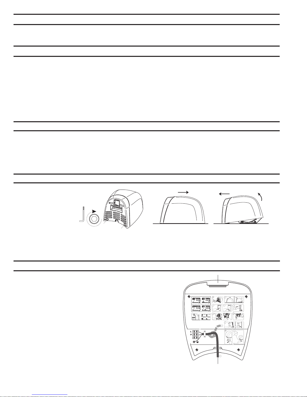
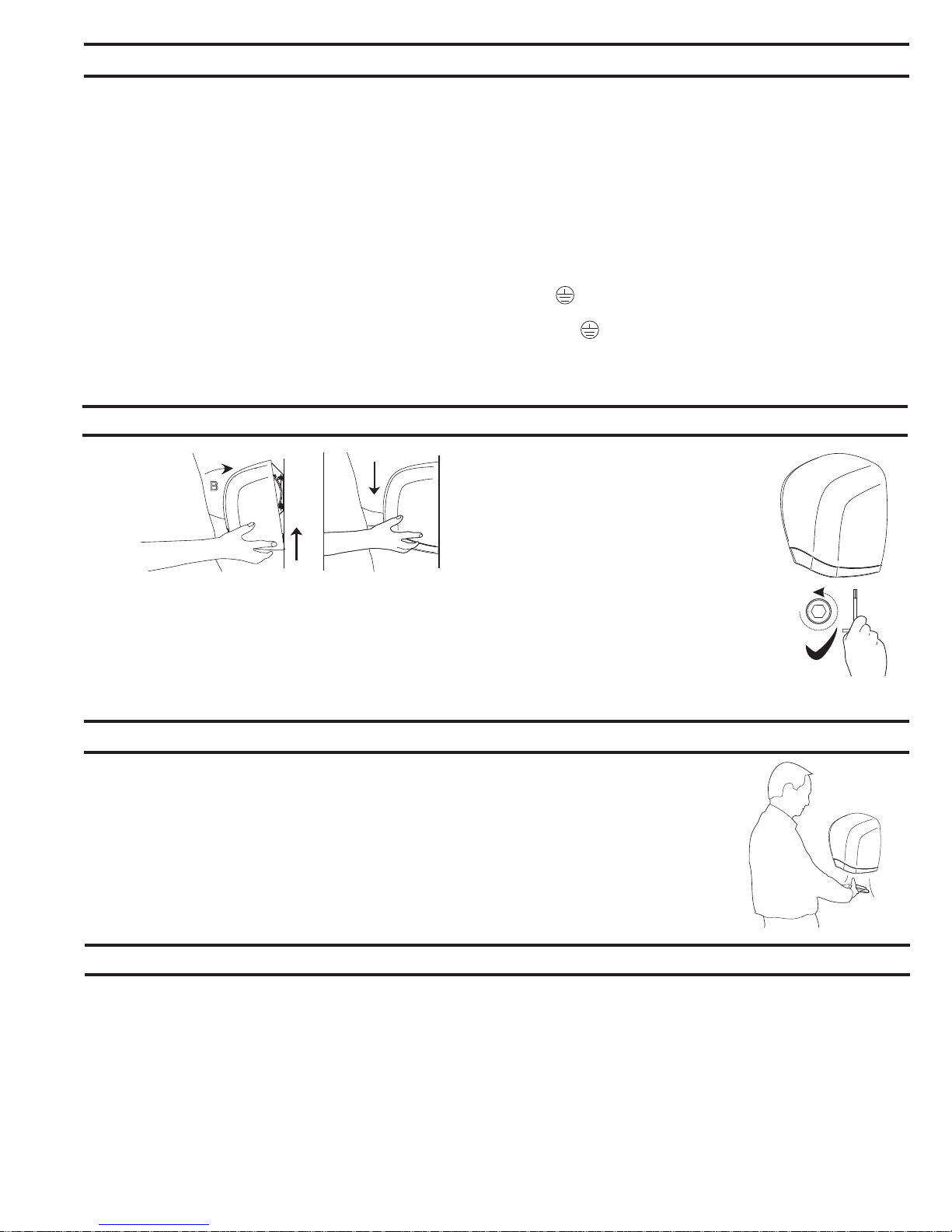
Removal of Cover
1. Start installation of dryer by
removing cover. To loosen
two cover bolts, insert Allen
Wrench (provided with dryer)
x 2
into holes located on bottom
of cover. Make sure
wrench fits into head
of cover bolts and turn
1
CLOCKWISE until bolts stop
turning. When cover bolts
are screwed out all the way,
cover can be removed.
Installation of Mounting Base
FOR PROPER ELECTRICAL CONNECTIONS, CHECK LOCAL
BUILDING CODE. UNIT MUST BE INSTALLED BY
A QUALIFIED LICENSED ELECTRICIAN
1. Hold the Installation Template against the wall in the desired
location of the installed dryer. See recommended mounting
heights above.
2. Make sure line on template representing bottom of dryer
mounting base is horizontal and located at the desired height
above floor.
NOTE: Surface-mounted electrical supply entry is located in the
bottom of the mounting base. Surface-mounted supply cable
should be fitted in a conduit.
3. Drill four holes for 1/4" (6.4mm) diameter mounting bolts or
screws (not furnished by Bobrick).
4. Fasten mounting base securely to wall.
2
Form No. 770-778-69_ii Multi Language (Issued 8/1/15) © 2015 Bobrick Washroom Equipment, Inc. Printed in U.S.A.
A
C
B
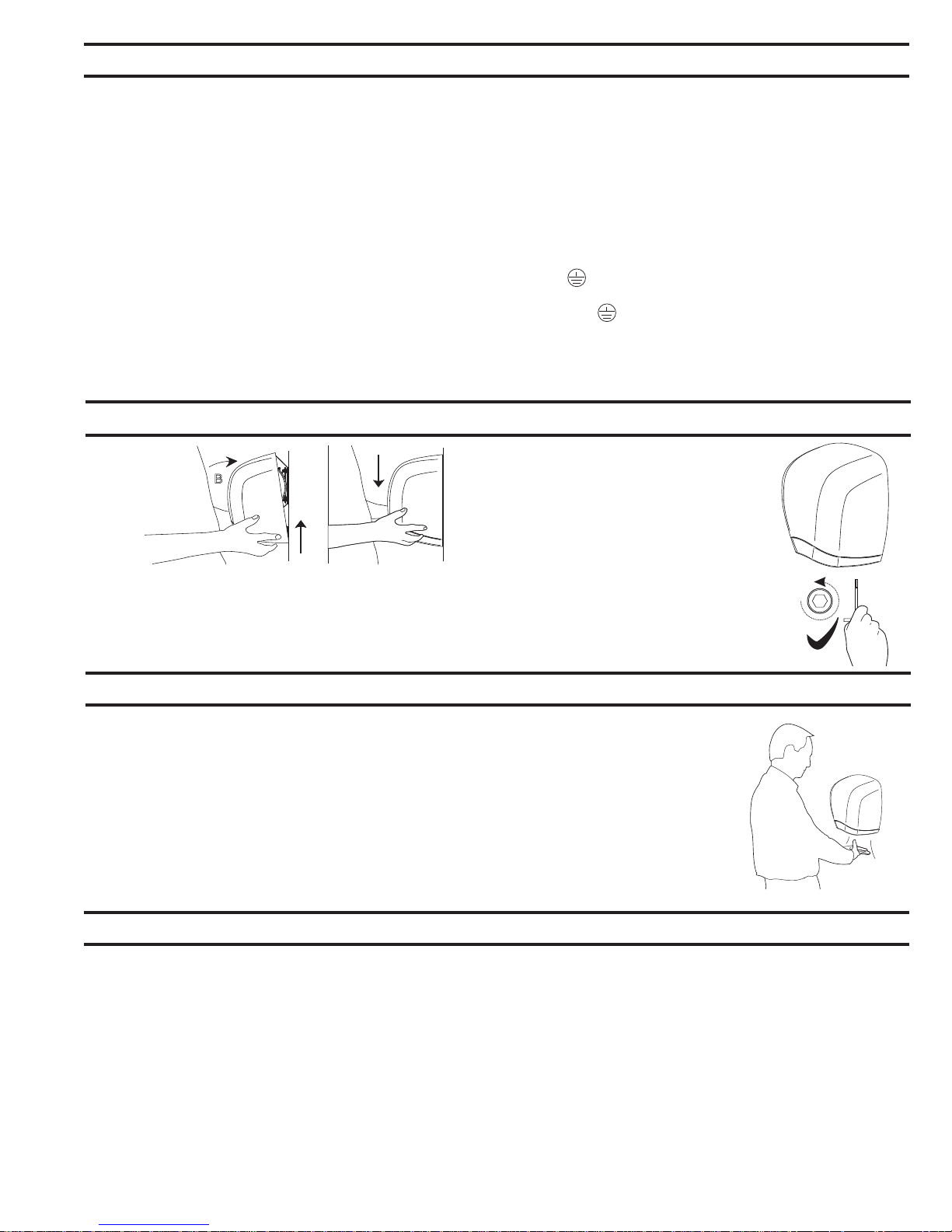
2. To remove cover, place a hand on each side of cover and
push up toward top of dryer releasing cover from studs at top
of mounting base. Lift cover off mounting base by pulling
forward at the bottom and upward at the same time.
WARNING: TURN ELECTRICAL POWER SUPPLY OFF
BEFORE MAKING ELECTRICAL CONNECTIONS. DRYER
MUST BE GROUNDED (EARTHED).
Page 3
Electrical Connection
FOR PROPER ELECTRICAL CONNECTIONS, CHECK LOCAL BUILDING CODE. UNIT MUST BE INSTALLED BY A QUALIFIED
LICENSED ELECTRICIAN
1. Connect dryer to nearest distribution panel. Use wire as required by local electrical code. In the United States and Canada use
No. 12 wire or larger.
2. Wiring Instructions:
a. This appliance is intended for connection to fixed wiring.
b. A fused means for disconnection in all poles must be provided in the fixed wiring in accordance with the wiring rules.
c. Check that the electrical rating shown on the Hand Dryer (rating label) is compatible with the electrical supply.
d. WARNING: THIS PRODUCT MUST BE EARTHED.
e. Installation and wiring must conform to current IEE Regulations (UK), local or appropriate regulation (other countries).
f. For 115 Volt Dryers: Connect ground/earth supply the terminal marked , the Live supply to terminal marked L and neutral
supply to terminal marked N. A DEDICATED LINE IS REQUIRED FOR EACH 115 VOLT DRYER.
g. For 208–240 Volt Dryers: Connect ground/earth supply the terminal marked and the 208-240 Volt wires to terminals
marked L (L1) and N (L2).
3. Secure electrical wire in strain relief clamp provided on mounting base.
Replace Cover
2. To tighten two cover bolts,
B
A
1. Replace cover by positioning top of cover on studs on top of
mounting base and tipping bottom of cover toward wall. Push
bottom of cover firmly against wall.
NOTE: Space between cover and wall must be the same on four
sides.
insert Allen wrench into
holes on bottom of cover.
Make sure wrench fits into
head of cover bolts and
turn COUNTERCLOCKWISE
until bolts are tightened.
NOTE: Do not overtighten cover
bolts; overtightening cover bolts
may damage enamel finish.
x 2
Check Dryer Operation
1. For AutoPilot Hand Dryers: Turn electrical power supply on. Position hands under nozzle and
dryer should turn on. Remove hands from under nozzle and dryer should stop.
Maintenance
WARNING: MOTOR LAMINATIONS ARE LIVE. TURN ELECTRICAL POWER SUPPLY OFF BEFORE DOING ANY
MAINTENANCE OR SERVICE TO DRYER. DRYER MUST NOT BE OPERATED UNLESS COVER IS IN PLACE.
FOR PROPER ELECTRICAL CONNECTIONS, CHECK LOCAL BUILDING CODE. UNIT MUST BE INSTALLED BY A QUALIFIED
LICENSED ELECTRICIAN
1. Exterior of cover should be cleaned with a damp cloth to remove dust and surface dirt. Do not use abrasive agents or solvents as
they may
permanently damage surface of cover.
2. At least once every 6 months remove cover. Using a small brush or vacuum, clean out buildup of dust and lint from air-intake grille
and baffle.
NOTE: if dryer is installed where there is a lot of dust and dirt in the air, the interior of the dryer should be cleaned out more
frequently.
Form No. 770-778-69_ii Multi Language (Issued 8/1/15) © 2015 Bobrick Washroom Equipment, Inc. Printed in U.S.A.
3
Page 4
C
L
C
L
>
0.5m
X
1
{
X
8mm
1.
2.
3.
3
A
B
C
4
5
6
B
A
10
x 2
1
2
x 2
8
A
4
B
4
4
B
Características Eléctricas
Secadores de manos models B-770, B-778, 115V CA, 20 A, 50/60 Hz, Monofásico, Clasificado cULus;
Secadores de manos models B-770, B-778, 208-240V CA, 9-10 A, 50/60 Hz, Monofásico, Clasificado cULus y marcado CE.
Alturas de Montaje Recomendadas
Alturas de montaje recomendadas: Distancia desde el suelo a los agujeros inferiores de montaje de la base de montaje (Dimensión A)
Secador de manos
Aseos para caballeros .............................................................................................................................................................................. 117cm (46'')
Aseos para señoras .................................................................................................................................................................................. 112cm (44'')
Aseos para niños, de 3 a 9 años .............................................................................................................................................................. 81cm (32'')
Aseos para niños, de 9 a 12 años ............................................................................................................................................................ 91cm (36'')
Aseos para niños, de 12 a 15 años .......................................................................................................................................................... 102cm (40'')
Aseos para niños, de 15 a 18 años .......................................................................................................................................................... 112cm (44'')
Acceso para sillas de ruedas ....................................................................................................................................................................97cm (38'')
* Los secadores de manos automáticos de Bobrick se deben instalar a 380mm (15") por encima de cualquier saliente o superficie horizontal
que pueda interferir con la operación del sensor automático.
Importante
* Secamanos por aire caliente. Diseñado para su uso en el hogar por parte de usuarios no expertos. No es adecuado para su uso al
aire libre.
** Este secamanos puede ser usado por niños de 8 años de edad y mayores y personas con capacidad física, sensorial o mental
reducida o personas con falta de experiencia o conocimiento que hubieren recibido supervisión o instrucciones en lo referente al
uso del secamanos en forma segura y que entiendan posibles riesgos supuestos. Los niños no deben jugar con este equipo. La
limpieza y mantenimiento del secamanos no debe ser realizado por niños sin supervisión adulta.
*** En caso de que ocurriera un defecto, desconecte el suministro eléctrico y llame a un electricista cualificado.
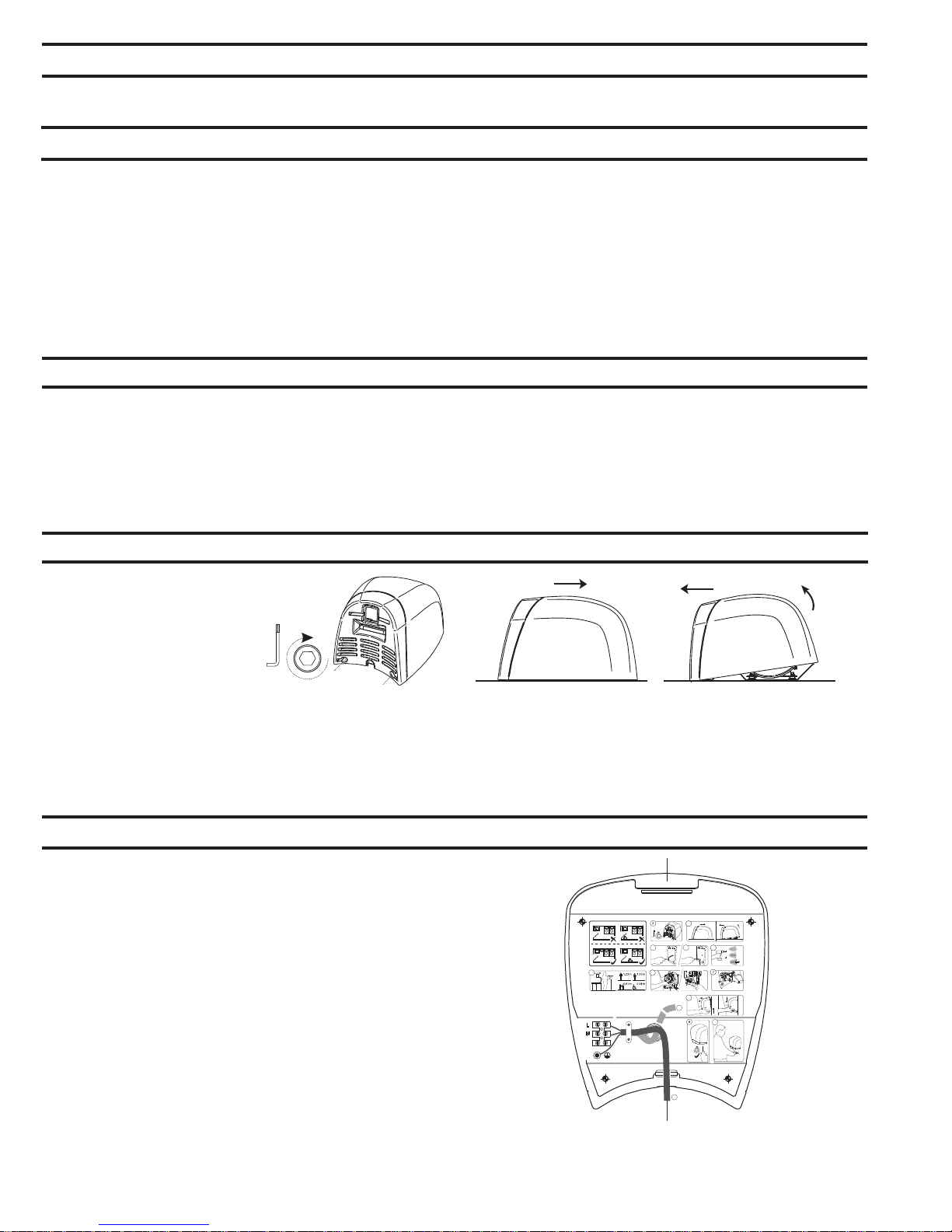
Cómo Quitar La Cubierta Del Secador
1. Comenzar la instalación del secador
quitando la cubierta. Para soltar los
dos pernos de la cubierta, insertar
la llave Allen provista con el
x 2
secador en los agujeros situados
en la parte inferior de la cubierta en
cada lado de la rejilla de entrada de
aire. Asegure que la llave cabe en la
1
2
cabeza de los pernos de la cubierta
y girarla en sentido dextrorso
(A LA DERECHA) hasta que los
pernos ya no giran. Cuando se han
roscado los pernos de la cubierta lo
más posible, se puede retirar la
cubierta.
Instalación De La Base De Montaje
LA INSTALACIÓN DEBE SER SUPERVISADA POR UN
ELECTRICISTA CUALIFICADO.
1. Coloque la plantilla de Instalación contra la pared en la posición
deseada del secador instalado. Consulte las alturas de montaje
recomendadas arriba.
2.
Asegúrese de que la línea en la plantilla que representa la parte
inferior de la base de montaje del secador esté a nivel horizontal y
situada a la wwaltura deseada del suelo.
NOTA: La entrada de la alimentación eléctrica montada en la superficie
está situada en la esquina derecha inferior de la base de montaje. El
cable de alimentación montado en la superficie debe colocarse en un
conducto.
3. Perforar cuatro agujeros para pernos o tornillos de montaje, de
diámetro 6 mm (1/4"), (no provistos por Bobrick).
4. Fijar la base firmemente sobre la pared
A
C
B
2. Para retirar la cubierta, colocar una mano en cada lado de la cubierta
y empujar hacia arriba hacia la parte superior del secador, soltando
la cubierta de las clavijas en la parte superior de la base de montaje.
Separar la cubierta de la base de montaje tirándola hacia delante y
arriba al mismo tiempo.
ADVERTENCIA: DESCONECTAR LA ALIMENTACIÓN DE RED ANTES
DE HACER LAS CONEXIONES ELÉCTRICAS. EL SECADOR TIENE
QUE ESTAR CONECTADO A TIERRA.
4
Form No. 770-778-69_ii Multi Language (Issued 8/1/15) © 2015 Bobrick Washroom Equipment, Inc. Printed in U.S.A.
Page 5
Conexión Eléctrica
PARA TENER LAS CONEXIONES ELÉCTRICAS CORRECTAS, CONSULTE EL CÓDIGO DE CONSTRUCCIÓN LOCAL. LA UNIDAD LA DEBE
INSTALAR UN ELECTRICISTA CAPACITADO CALIFICADO.
1. Conectar el secador al tablero de distribución más cercano. Usar el tipo de cable exigido por el código eléctrico local. En los Estados Unidos y
Canadá, usar alambre #12 o más pesado.
2. Instrucciones de cableado:
a. Este secamanos esta diseñado para su conexión a un cableado eléctrico fijo.
b. El cableado fijo debe incorporar un dispositivo interruptor de fusibles, para desconexión de todos los polos, según las normas de cableado.
c. Verifique que la potencia eléctrica indicada en el Secamanos (véase la etiqueta de potencia eléctrica) es compatible con el suministro eléctrico.
d. ADVERTENCIA: ESTE PRODUCTO DEBE ESTAR CONECTADO A TIERRA.
e. La instalación y el cableado deben cumplir con los requisitos exigidos por las Normas IEE existentes (Reino Unido) o las normas locales o
apropiadas (otros países).
f. Secadores de 115 voltios: Conecte el suministro a tierra al terminal marcado , el suministro eléctrico Con Corriente al terminal marcado
(L) y el Neutro al terminal marcado (N). SE NECESITA UNA LÍNEA DEDICADA PARA CADA SECADOR DE 115 VOLTIOS.
g. Secadores de 208-240 voltios: Conecte el suministro a tierra al terminal marcado , el suministro eléctrico Con Corriente al terminal
marcado (L) y el Neutro al terminal marcado (N).
3. Sujetar el cable eléctrico usando la abrazadera de alivio de tensión provista en la base de montaje.
Restitución De La Cubierta
2. Para apretar los dos pernos de la
cubierta insertar la llave Allen
B
A
1. Reponer la cubierta colocando la parte superior de la cubierta sobre
las clavijas en la parte superior de la base de montaje y girando la
parte inferior de la cubierta hacia la pared. Empujar la parte inferior
de la cubierta firmemente contra la pared.
NOTA: El espacio entre la pared y la cubierta debe ser igual en los
cuatro lados.
provista con el secador, en los
agujeros situados en la parte inferior
de la cubierta. Asegure que la
llave cabe en la cabeza de los
pernos de la cubierta y girarla en
sentido sinistrorso (A LA
IZQUIERDA) hasta que los pernos
están apretados.
NOTA: No apretar excesivamente los
pernos de la cubierta porque podría
dañar el acabado esmaltado vidrioso.
x 2
Verificación De La Operación Del Secador
1. Los Secadores de Manos AutoPilot: Conectar el secador a la alimentación. Colocar las manos debajo
de la tobera y el secador debe encenderse automáticamente. Quitando las manos de debajo la tobera debe
apagarlo.
Mantenimiento
ADVERTENCIA: TENER EN CUENTA QUE LAS LAMINACIONES DEL MOTOR ESTÁN BAJO TENSIÓN. DESCONECTAR LA ALIMENTACIÓN
DE RED ANTES DE HACER CUALQUIER TRABAJO DE REVISIÓN O MANTENIMIENTO DEL SECADOR. NO OPERAR EL SECADOR SIN
TENER LA CUBIERTA INSTALADA.
LA INSTALACIÓN DEBE SER SUPERVISADA POR UN ELECTRICISTA CUALIFICADO.
1. Se debe limpiar el exterior de la cubierta con un paño húmedo para quitar cualquier polvo o suciedad. No usar agentes abrasivos ni solventes
porque pueden dañar permanentemente la superficie de la cubierta.
2. Al menos cada seis meses, quitar la tapa y limpiar el secador con un cepillo pequeño o con un aspirador, y eliminar cualquier acumulación de
polvo en la rejilla de entrada y el deflector.
NOTA: Si se ha instalado el secador en un sitio de mucho polvo y suciedad en el aire, se debe limpiar el interior del secador con mayor frecuencia.
Form No. 770-778-69_ii Multi Language (Issued 8/1/15) © 2015 Bobrick Washroom Equipment, Inc. Printed in U.S.A.
5
Page 6

C
L
C
L
>
0.5m
X
1
{
X
8mm
1.
2.
3.
3
A
B
C
4
5
6
B
A
10
x 2
1
2
x 2
8
A
4
B
4
4
B
Elektrische Daten
Händetrockner models B-770, B-778, 115 V WS, 20 A, 50/60 Hz, einphasig, cULus -geprüft
Händetrockner models B-770, B-778, 208-240 V WS, 9-10 A, 50/60 Hz, einphasig, cULus -geprüft, tragen das CE-Kennzeichen.
Empfohlene Einbauhöhen
Abstand zwischen Boden und unteren Löchern für Befestigungsschrauben an der Grundplatte (Abmessung A)
Handtrockner
Waschräume (Männer) .............................................................................................................................................................................117cm (46'')
Waschräume (Frauen) .............................................................................................................................................................................. 112cm (44'')
Waschräume (Kinder von 3-9 Jahren) ...................................................................................................................................................... 81cm (32'')
Waschräume (Kinder von 9-12 Jahren) .................................................................................................................................................... 91cm (36'')
Waschräume (Kinder von 12-15 Jahren) .................................................................................................................................................. 102cm (40'')
Waschräume (Kinder von 15-18 Jahren ................................................................................................................................................... 112cm (44'')
Zugang im Rollstuhl .................................................................................................................................................................................. 97cm (38'')
* Um jegliche Stoerung der Operation des Trockners zu vermeiden, Bobrick's automatische Haende Trockner solte auf einer Hoehe von
380mm (15") ueber einen Wandvorbau oder einer horizontale Flaeche montiert werden.
Wichtig
* Warmluft-Händetrockner. Gedacht zur Nutzung durch Normalverbraucher in Haushalten. Nicht geeignet für den Einsatz im Freien.
** Dieses Gerät kann von Kindern ab 8 Jahren und Personen mit eingeschränkten körperlichen, sensorischen oder geistigen
Fähigkeiten oder mangelnder Erfahrung und Kenntnisse benutzt werden, wenn sie während der Nutzung überwacht werden oder in
der sicheren Nutzung des Gerätes unterwiesen wurden und die damit verbundenen Gefahren verstehen. Kinder dürfen nicht mit dem
Gerät spielen. Reinigung und Benutzerpflege dürfen nicht unbeaufsichtigt von Kindern durchgeführt werden.
*** Wenn ein Fehler auftritt, muss das Gerät von der Stromversorgung getrennt und ein qualifizierter Elektriker darüber informiert
werden.
Entfernen Des Gehäuses
1. Beginnen Sie mit dem Einbau des
Trockners, indem Sie das Gehäuse
entfernen. Schieben Sie zum Lösen
der zwei Gehäuseschrauben den mit
x 2
dem Trockner gelieferten
Innensechskantschlüssel in die Löcher
am Unterteil des Gehäuses auf beiden
1
Seiten des Lufteinlassgitters ein.
Stellen Sie sicher, dass der Schlüssel in
die Schraubköpfe der Gehäuseschrauben
passt und drehen Sie IM
UHRZEIGERSINN, bis sich die
Schrauben nicht mehr drehen. Wenn die Gehäuseschrauben ganz
eingeschraubt sind, kann das Gehäuse entfernt werden
Einbau Der Grundplatte
DIE INSTALLATION MUSS VON EINEM QUALIFIZIERTEN
ELEKTRIKER DURCHGEFÜHRT WERDEN.
1. Bitte verwenden Sie die Schablone für die Montage. Beachten Sie bitte
die entsprechende Montagehöhe Halten Sie die Schablone gegen die
Wand am gewünschten Ort des Siehe empfohlene Aufstellhöhen oben.
2. Vergewissern Sie sich, daß die Linie auf der Vorlage, Schablonde, die die
Unterkante der Befestigungsplatte des Trockners darstellt, horizontal ist
und sich auf der gewünschten Höhe über dem Boden befindet.
HINWEIS: Die Stromversorgung bei Modellen für Wandeinbau befindet
sich in der rechten unteren Ecke der Grundplatte. Der Flansch der
Grundplatte und das Unterteil des Gehäuses sind in der Ecke unten
rechts mit Kerben versehen, um den Anschluss des Isolierrohrs
aufzunehmen.
3. Bohren Sie vier Löcher für Befestigungsschrauben mit 6,35 mm
Durchmesser (nicht von Bobrick geliefert).
4. Befestigen Sie die Grundplatte sicher an der Wand.
6
Page 6
Form No. 770-778-69_ii Multi Language (Issued 8/1/15) © 2015 Bobrick Washroom Equipment, Inc. Printed in U.S.A.
A
C
B
2
2. Zum Entfernen des Gehäuses halten Sie die Seiten des Gehäuses
mit beiden Händen fest und schieben es in Richtung des Oberteils
des Trockners, wobei das Gehäuse von den Stiftschrauben oben an
der Grundplatte gelöst wird. Heben Sie das Gehäuse von der
Grundplatte weg, indem Sie das untere Teil gleichzeitig vorwärts und
nach obe ziehen.
ADVERTENCIA: DESCONECTAR LA ALIMENTACIÓN DE RED ANTES
DE HACER LAS CONEXIONES ELÉCTRICAS. EL SECADOR TIENE
QUE ESTAR CONECTADO A TIERRA.
Page 7

Elektrischer Anschluss
FÜR EINEN ORDNUNGSGEMÄSSEN ELEKTRISCHEN ANSCHLUSS SEHEN SIE BITTE DIE ÖRTLICHEN BAUVORSCHRIFTEN EIN. DAS
GERÄT MUSS VON EINEM QUALIFIZIERTEN UND DAZU BEFÄHIGTEN ELEKTRIKER EINGEBAUT WERDEN.
1. Schließen Sie den Trockner an der nächstgelegenen Verteilertafel an. Verwenden Sie die Drähte den örtlichen Vorschriften entsprechend. In den
USA und Kanada verwenden Sie Draht #12 oder größer.
2. Verdrahtungsanleitung:
a. Dieses Gerät ist zum Anschluss über feste Verkabelung gedacht.
b. Eine mit Sicherung versehene Vorrichtung zur Unterbrechung an allen Polen muss in der Festverdrahtung den Verdrahtungsvorschriften
entsprechend angebracht sein.
c. Überprüfen Sie, dass die auf dem Handtrockner angegebene Nennleistung (Typenschild) mit der elektrischen Zuleitung kompatibel ist.
d. WARNUNG: DIESES PRODUKT MUSS GEERDET SEIN.
e. Installation und Verkabelung müssen den aktuellen IEE-Richtlinien (UK), örtlichen oder einschlägigen Bestimmungen (andere Länder)
entsprechen.
f. Für Trockner mit 115 Volt: Den Masse-/Erdanschluss mit der mit dem Erdungssymbol gekennzeichneten, den Phasenleiter mit der mit
(L) gekennzeichneten und den Neutralleiter mit der mit (N) gekennzeichneten Klemme verbinden. FÜR JEDEN TROCKNER MIT 115 VOLT IST
EINE SPEZIELLE LEITUNG ERFORDERLICH.
g. Für Trockner mit 208-240 Volt: Den Masse-/Erdanschluss mit der mit dem Erdungssymbol gekennzeichneten, den Phasenleiter mit
der mit (L) gekennzeichneten und den Neutralleiter mit der mit (N) gekennzeichneten Klemme verbinden.
3. Befestigen Sie den Draht an der Zugentlastungsklemme, die an der Grundplatte angebracht ist.
Erneutes Anbringen Des Gehäuses
2. Schieben Sie zum Anziehen
B
A
1. Bringen Sie das Gehäuse wieder an, indem Sie das obere Teil des
Gehäuses auf Stiftschrauben oben in der Grundplatte positionieren
und das Unterteil des Gehäuses in Richtung Wand kippen. Drücken
Sie das Unterteil des Gehäuses fest an die Wand.
HINWEIS: Der Raum zwischen dem Gehäuse und der Wand muss
auf allen vier Seiten gleich sein.
der zwei Gehäuseschrauben den
Innensechskantschlüssel in die
Löcher unten im Gehäuse ein.
Stellen Sie sicher, dass der
Schlüssel in die Schraubköpfe der
Gehäuseschrauben passt und
drehen Sie ENTGEGEN DEM
UHRZEIGERSINN, bis die
Schrauben angezogen sind.
HINWEIS: Ziehen Sie die
Gehäuseschrauben nicht übermäßig
an, da sonst die Emaillierung beschädigt
werden könnte.
x 2
1. Für AutoPilot-Handtrockner: Schalten Sie die Stromversorgung ein. Halten Sie die Hände unter die Düse,
woraufhin sich der Trockner einschalten müsste. Wenn Sie die Hände von der Düse entfernen, müsste das ein
Ausschalten des Trockners bewirken.
WARNHINWEIS: ANKERFOLIEN SIND STROMFÜHREND. SCHALTEN SIE DIE STROMVERSORGUNG AUS, BEVOR IRGENDWELCHE
WARTUNGS- ODER INSTANDHALTUNGSARBEITEN AM TROCKNER AUSGEFÜHRT WERDEN. DER TROCKNER DARF NUR BE
ANGEBRACHTEM GEHÄUSE
DIE INSTALLATION MUSS VON EINEM QUALIFIZIERTEN ELEKTRIKER DURCHGEFÜHRT WERDEN.
BETRIEBEN WERDEN.
1. Das Äußere des Gehäuses muss mit einem feuchten Tuch abgewischt werden, um Staub und Oberflächenschmutz zu entfernen.
Verwenden Sie keine Scheuermittel oder Lösungsmittel, da sie die Gehäuseoberfläche permanent beschädigen könnten.
2. Nehmen Sie das Gehäuse mindestens alle 6 Monate einmal ab. Entfernen Sie mit einer kleinen Bürste oder einem kleinen Staubsauger
eine Ansammlung von Staub oder Fussel vom Lufteinlassgitter und Ablenkblech. HINWEIS: Wenn ein Trockner an einem Ort mit viel Staub und
Schmutz in der Luft installiert ist, muss das Innere des Trockners häufiger gereinigt werden.
Form No. 770-778-69_ii Multi Language (Issued 8/1/15) © 2015 Bobrick Washroom Equipment, Inc. Printed in U.S.A.
Prüfen Des Trocknerbetriebs
Wartung
7
Page 8

C
L
C
L
>
0.5m
X
1
{
X
8mm
1.
2.
3.
3
A
B
C
4
5
6
B
A
10
x 2
1
2
x 2
8
A
4
B
4
4
B
Caractéristiques Électriques
Modèles de sèche-mains B-770, B-778, 115 V c.a., 20 A, 50/60 Hz, monophasé, homologués cULus.
Modèles de sèche-mains B-770, B-778, 208-240 V c.a., 9-10 A, 50/60 Hz, monophasé, homologués UL et cULus, marquage CE.
Hauteurs de Montage Recommandées
Distance du sol aux trous des vis de montage de la partie inférieure du socle (Dimension A)
Sèche-mains
Cabinet de toilette hommes ...................................................................................................................................................................... 117 cm (46'')
Cabinet de toilette femmes ....................................................................................................................................................................... 112 cm (44'')
Cabinet de toilette enfants, âges 3-9 ........................................................................................................................................................81 cm (32'')
Cabinet de toilette enfants, âges 9-12 ......................................................................................................................................................91 cm (36'')
Cabinet de toilette enfants, âges 12-15 ....................................................................................................................................................102 cm (40'')
Cabinet de toilette enfants, âges 15-18 ....................................................................................................................................................112 cm (44'')
Pour handicapés ....................................................................................................................................................................................... 97 cm (38'')
* Pour l'installation il est necessaire de respecter une distance minimale de 380mm (15") au dessous du sèche-mains automatique, pour
empécher une d'eclanchement permanant.
Important
* Sèche-mains à air chaud. Conçu pour un usage domestique par des utilisateurs sans connaissances spéciales. Ne convient pas à un
usage à l'extérieur.
** Cet appareil peut être utilisé par des enfants à partir de 8 ans, et par des personnes présentant des capacités physiques, sensorielles
ou mentales réduites, ou un manque d'expérience ou de connaissances si celles-ci sont sous surveillance ou ont reçu des
instructions concernant l'utilisation de l'appareil en toute sécurité et si elles maîtrisent les risques impliqués. Les enfants ne
doivent pas jouer avec cet appareil. Le nettoyage et l'entretien par l'utilisateur ne doivent pas être effectués par des enfants sans
surveillance.
*** Si un défaut se manifeste, débrancher l'alimentation électrique et faire appel à un électrici
Retrait Du Couvercle
1. Commencer l’installation du
sèche-mains en retirant le
couvercle. Pour desserrer
les deux boulons du
x 2
couvercle, introduire une clé
Allen, fournie avec l’appareil,
dans les trous situés sur la
1
partie inférieure du couvercle,
de chaque côté de la grille
d’entrée d’air. Vérifier que la clé est bien introduite dans la tête des
boulons du couvercle, puis tourner dans LE SENS DES AIGUILLES
D’UNE MONTRE jusqu’à ce que les boulons ne puissent plus
tourner. Après avoir serré à fond les boulons du couvercle, il est
possible de retirer le couvercle.
Installation Du Socle
SON INSTALLATION DOIT ÊTRE SUPERVISÉE PAR UN
ÉLECTRICIEN QUALIFIÉ.
1. Placer le socle sur le mur à l’endroit voulu pour l’installation du
sèchemains. Voir le tableau des hauteurs de montage recommandées.
2. Utiliser le socle ou le gabarit fourni avec le sèche-mains pour marquer
l’endroit prévu pour les quatre trous de montage et le trou d’accès pour
le câble électrique (si ce câble est dissimulé dans le mur et entre dans le
sèche-mains par l’arrière du socle).
NOTA: L’entrée prévue pour le câble électrique monté en surface est
située dans le coin en bas à droite du socle. La bride du socle et la partie
inférieure du couvercle comportent des encoches dans le coin en bas à
droite prévu pour recevoir la connexion du conduit électrique.
3. Percer quatre trous pour les boulons de montage ou vis de 6,35 mm de
diamètre (non fournis par Bobrick).
4. Bien fixer le socle au mur.
8
Form No. 770-778-69_ii Multi Language (Issued 8/1/15) © 2015 Bobrick Washroom Equipment, Inc. Printed in U.S.A.
A
C
B
2
2. Pour retirer le couvercle, placer une main de chaque côté du
couvercle, puis le pousser vers le haut de l’appareil afin de dégager
le couvercle des languettes situées sur la partie supérieure du socle.
Soulever le couvercle du socle, en tirant simultanément le bas vers
l’avant et le haut.
AVERTISSEMENT : AVANT D’EFFECTUER TOUT
RACCORDEMENT ÉLECTRIQUE, COUPER L’ALIMENTATION ÉLECTRIQUE.LE
SÈCHE-MAINS / SÈCHE-CHEVEUX DOIT ÊTRE MIS A LA TERRE.
Page 9

Branchement Electrique
POUR EFFECTUER UN RACCORDEMENT ÉLECTRIQUE CORRECT, VÉRIFIER LE CODE LOCAL DE CONSTRUCTION. IL EST IMPÉRATIF DE
FAIRE INSTALLER CET APPAREIL PAR UN ÉLECTRICIEN QUALIFIÉ COMPÉTENT.
1. Brancher le sèche-mains/sèche-cheveux au tableau de distribution le plus proche. Utiliser le câble exigé par le code local d’électricité. Aux États Unis et au Canada, utiliser du câble N° 12 ou plus gros.
2. Instructions de câblage:
a. Cet appareil est destiné à être connecté à un câblage fixe.
b. Il faut prévoir un dispositif à fusible pour déconnexion dans tous les pôles, incorporé dans le câblage fixe conformément aux réglements
d’installation.
c. Vérifier que la tension électrique nominale indiquée sur le sèche-mains (étiquette signalétique) est compatible avec la tension électrique.
d. AVERTISSEMENT : IL EST IMPÉRATIF DE METTRE CET APPAREIL À LA TERRE.
e. L'installation et le câblage doivent être conformes aux règlements IEE actuels (R-U), aux règlements locaux ou appropriés (pour les autres
pays).
f. Sèche-mains/Sèche-cheveux de 115 V: Raccorder l'alimentation de mise à la terre / masse à la borne marquée , l'alimentation sous
tension à la borne marquée (L) et l'alimentation neutre à la borne marquée (N). Nota : IL FAUT PRÉVOIR UN CÂBLE SPÉCIAL POUR
CHAQUE APPAREIL DE 115 V.
g. Sèche-mains/Sèche-cheveux de 208-240 V: Raccorder l'alimentation de mise à la terre / masse à la borne marquée , l'alimentation sous
tension à la borne marquée (L) et l'alimentation neutre à la borne marquée (N).
3. Fixer le câble électrique dans la pince de décharge des contraintes prévue sur le socle.
Remettre Le Couvercle
2. Pour serrer les deux boulons d
B
A
1. Remettre le couvercle en plaçant la partie supérieure du couvercle
sur les goujons situés sur le haut du socle, et en inclinant la partie
inférieure du couvercle vers le mur. Plaquer fermement la partie
inférieure du couvercle contre le mur.
NOTA: La distance entre le couvercle et le mur doit être égale sur les
quatre côtés.
couvercle, introduire une clé Allen
dans les trous de la partie inférieure
du couvercle. Vérifier que la clé est
bien introduite dans la tête des
boulons du couvercle, puis tourner
dans le SENS CONTRAIRE DES
AIGUILLES D’UNE MONTRE jusqu’à
ce que le boulons soient serrés.
NOTA: Ne pas trop serrer les boulons
du couvercle, sinon cela risque
d’endommager la finition émaillée.
x 2
Verifier Le Fonctionnement Du Seche-Mains
1. Pour les sèche-mains à autopilote: Mettre l’appareil sous tension. Placer les mains sous la buse. Le sèche-
mains doit s’allumer. Retirer les mains de la trajectoire sous la buse. Le sèche-mains doit s’arrêter.
Maintenance
AVERTISSEMENT: LES DISQUES EN TÔLE D’INDUIT DU MOTEUR SONT SOUS TENSION. COUPER L’ALIMENTATION ÉLECTRIQUE AVANT
D’INTERVENIR POUR UNE OPÉRATION D’ENTRETIEN OU DE RÉPARER LE SÈCHE-MAINS. SI LE COUVERCLE N’EST PAS EN PLACE, IL NE
FAUT PAS UTILISER LE SÈCHE-MAINS.
SON INSTALLATION DOIT ÊTRE SUPERVISÉE PAR UN ÉLECTRICIEN QUALIFIÉ.
1. L’extérieur du couvercle doit être nettoyé avec un chiffon humide pour éliminer la poussière et la saleté en surface. Ne pas utiliser de produits
abrasifs ou de solvants car ils risquent d’endommager irrémédiablement la surface du couvercle.
2. Au moins une fois tous les six mois, retirer le couvercle. À l’aide d’un petit pinceau ou d’un aspirateur, éliminer tout dépôt de poussière et de
peluche de la grille d’antrée d’air et du déflecteur.
NOTA: Si le sèche-mains est installé là où il y a beaucoup de poussière et de saleté dans l’air, l’intérieur du sèche-mains doit être nettoyé plus
fréquemment.
Form No. 770-778-69_ii Multi Language (Issued 8/1/15) © 2015 Bobrick Washroom Equipment, Inc. Printed in U.S.A.
9
Page 10

C
L
C
L
>
0.5m
X
1
{
X
8mm
1.
2.
3.
3
A
B
C
4
5
6
B
A
10
x 2
1
2
x 2
8
A
4
B
4
4
B
2
Dati Elettrici
Modelli di asciuganaiu B-770, B-778, 115V c.a., 20 A, 50/60 Hz, monofase, omologati cULus;
Modelli di asciuganaiu B-770, B-778, 208-240V c.a., 9-10 A, 50/60 Hz, monofase, omologati cULus, e quello CE.
Altezze Consigliate Per Il Montaggio
Distanza dal pavimento ai fori per le viti di montaggio che si trovano sul fondo della base di montaggio. (Dimensione A)
Toilette uomini ...........................................................................................................................................................................................117 cm (46'')
Toilette donne ...........................................................................................................................................................................................112 cm (44'')
Toilette bambini, 3-9 anni ..........................................................................................................................................................................81 cm (32'')
Toilette bambini, 9-12 anni ........................................................................................................................................................................91 cm (36'')
Toilette ragazzi, 12-15 anni .......................................................................................................................................................................102 cm (40'')
Toilette ragazzi, 15-18 anni .......................................................................................................................................................................112 cm (44'')
Per accesso con sedia a rotelle ................................................................................................................................................................97 cm (38'')
* Gli asciugamani automatici Bobrick vanno installati a 380mm (15") da qualsiasi protrusione o superificie orizzontale che potrebbe interferire con
l'operazione del sensore automatico.
Asciugamani
Importante
* Asciugamani ad aria calda. Ideale per l'uso in ambiente domestico da utenti non esperti. Non è indicato per l'uso all'aperto.
** Questo apparecchio può essere utilizzato da bambini dagli 8 anni in su e da persone che presentano ridotte capacità fisiche,
sensoriali o mentali o che difettano della necessaria esperienza e/o conoscenza, purché siano adeguatamente sorvegliati o addestrati
sull'uso dell'apparecchio in sicurezza e siano a conoscenza dei rischi correlati. I bambini non devono giocare con l'apparecchio, e
non possono pulirlo o effettuarne la manutenzione senza un'adeguata sorveglianza.
*** In caso di guasto, staccare la presa di corrente e rivolgersi a un elettricista qualificato.
Rimozione Della Carcassa
1. Iniziare l’installazione
dell’asciugamano rimuovendo la
carcassa. Per allentare due bulloni
della carcassa inserire la chiave a
x 2
brugola, fornita in dotazione con
l’asciugamano, nei fori che si trovano
sul fondo della carcassa su ciascun
1
lato della griglia di entrata dell’aria.
Assicurarsi che la chiave
corrisponda alla testa dei bulloni della carcassa e ruotare IN SENSO
ORARIO finché i bulloni non smettono di girare. Quando i bulloni della
carcassa sono inseriti fino in fondo, la carcassa può essere rimossa.
2. Per rimuovere la carcassa, mettere una mano su ciascun lato della
carcassa e spingere in alto verso la parte superiore dell’asciugatore
per rilasciare la carcassa dai perni di supporto che si trovano sulla
parte superiore della base di montaggio. Sollevare la carcassa, per
allontanarla dalla base di montaggio, tirando in avanti e verso l’alto
allo stesso tempo.
Installazione Della Base Di Montaggio
L'INSTALLAZIONE DEVE ESSERE DIRETTA DA UN ELETTRICISTA QUALIFICATO.
1. Collocare la base di montaggio sulla parete nella posizione in cui si
desidera posizionare l’asciugamano installato. Vedere le altezze
consigliate per il montaggio specificate sopra.
2. Usare la base di montaggio o la sagoma fornita con l’asciugamano
per marcare l’ubicazione dei quattro fori per le viti di montaggio ed il
foro di accesso per il cablaggio elettrico se l’alimentazione elettrica
è nascosta nel muro ed entrerà nell’asciugamano dal retro attraverso
la base di montaggio.
NOTA: L’alimentazione elettrica a parete è attaccata alla base di
montaggio nell’angolo inferiore destro. La flangia della base di montaggio
e il fondo della carcassa sono dentellati in prossimità dell’angolo inferiore
destro per alloggiare il collegamento del tubo del cablaggio elettrico.
3. Praticare quattro fori per i bulloni di montaggio del diametro di 6,4mm
o viti (non forniti da Bobrick).
4. Fissare la base di montaggio in modo ben saldo alla parete.
AVVERTENZA: METTERE FUORI SERVIZIO L’ALIMENTAZIONE DI
CORRENTE PRIMA DI ESEGUIRE I COLLEGAMENTI ELETTRICI.
L’ASCIUGAMANO DEVE ESSERE MESSO A TERRA (A MASSA).
A
C
B
10
Form No. 770-778-69_ii Multi Language (Issued 8/1/15) © 2015 Bobrick Washroom Equipment, Inc. Printed in U.S.A.
Page 11

Collegamento Elettrico
PER ESEGUIRE CORRETTAMENTE I COLLEGAMENTI ELETTRICI, VERIFICARE LE NORMATIVE LOCALI SULLE COSTRUZIONI.
L’APPARECCHIO DEVE ESSERE INSTALLATO DA UN ELETTRICISTA AUTORIZZATO QUALIFICATO.
1. Collegare l’asciugamano al quadro di distribuzione più vicino. Usare il filo come richiesto dalle normative elettriche locali. Negli Stati Uniti e in
Canada usare un cavo #12 o maggiore.
2. Istruzioni per il cablaggio:
a. Questo apparecchio deve essere collegato a un cablaggio fisso.
b. Ai fini della disconnessione di tutti i terminali, l’impianto elettrico fisso deve essere munito di un dispositivo con fusibile conforme alle norme
elettriche vigenti.
c. Verificare che la potenza elettrica nominale riportata sull'asciugamani (targhetta energetica) sia compatibile con l'alimentazione elettrica.
d. AVVERTENZA: QUESTO PRODOTTO DEVE ESSERE MESSO A TERRA.
e. L'installazione e il cablaggio devono essere conformi alle direttive IEE (nel Regno Unito), locali o pertinenti (in altri paesi) in vigore.
f. Per gli asciugamani da 115 Volt: Collegare la presa di terra (massa) al morsetto contrassegnato , il conduttore sotto tensione al morsetto
contrassegnato (L) e il cavo neutro al morsetto contrassegnato (N). N. PER CIASCUN ASCIUGAMANO DA 115 VOLT È NECESSARIA UNA
LINEA DEDICATA.
g. Per gli asciugamani da 208-240 Volt: Collegare la presa di terra (massa) al morsetto contrassegnato , il conduttore sotto tensione al
morsetto contrassegnato (L) e il cavo neutro al morsetto contrassegnato (N).
3. Fissare il cavo elettrico nel morsetto di protezione fornito sulla base di montaggio.
Controllare Il Funzionamento Dell’Asciugamano
2. Per serrare due bulloni della carcassa,
B
A
1. Riporre a posto la carcassa posizionando la parte superiore della
carcassa sui perni di supporto che si trovano sulla parte superiore
della base di montaggio e inclinando il fondo della carcassa verso la
parete. Spingere in modo deciso il fondo della carcassa contro la
parete.
NOTA: Lo spazio tra la carcassa e la parete deve essere lo stesso su tutti
e quattro i lati.
inserire la chiave a brugola nei fori
che si trovano sul fondo della
carcassa. Assicurarsi che la chiave
corrisponda alla testa dei bulloni
della carcassa e ruotare IN SENSO
ANTIORARIO finché i bulloni non
sono ben serrati.
NOTA: Non stringere eccessivamente
i bulloni della carcassa, per evitare di
danneggiare la finitura in smalto.
x 2
Controllare Il Funzionamento Dell’Asciugamano
Per verificare il funzionamento dell’asciugamano, seguire le seguenti istruzioni:
1. Per gli asciugamani ad accensione automatica: Attivare l’alimentazione elettrica. Posizionare le mani sotto il
boccaglio e l’asciugatore dovrebbe accendersi. Togliendo le mani da sotto il boccaglio, l’asciugatore dovrebbe
fermarsi.
Manutenzione
AVVERTENZA: IL LAMIERINO MAGNETICO È SOTTO TENSIONE. METTERE FUORI SERVIZIO L’ALIMENTAZIONE ELETTRICA PRIMA DI
ESEGUIRE QUALSIASI OPERAZIONE DI MANUTENZIONE O ASSISTENZA SULL’ASCIUGAMANO. L’ASCIUGAMANO NON DEVE ESSERE
ATTIVATO SE LA CARCASSA NON SI TROVA IN POSIZIONE.
L'INSTALLAZIONE DEVE ESSERE DIRETTA DA UN ELETTRICISTA QUALIFICATO.
1. Pulire la superficie esterna della carcassa con un panno umido per rimuovere la polvere e lo sporco superficiale. Non usare agenti abrasivi o
solventi, in quanto potrebbero danneggiare la superficie della carcassa in modo permanente.
2. La carcassa va rimossa almeno una volta ogni 6 mesi. Servendosi di una spazzolina o di un aspirapolvere, pulire l’accumulo di polvere e lanugine
dalla griglia della presa dell’aria e dal diaframma.
NOTA: Se l’asciugamano è installato in un luogo dove c’è molta polvere e sporco nell’aria, è necessario pulire più spesso l’interno dell’asciugamano.
Form No. 770-778-69_ii Multi Language (Issued 8/1/15) © 2015 Bobrick Washroom Equipment, Inc. Printed in U.S.A.
11
Page 12

C
L
C
L
>
0.5m
X
1
{
X
8mm
1.
2.
3.
3
A
B
C
4
5
6
B
A
10
x 2
1
2
x 2
8
A
4
B
4
4
B
1
电气特征
B-770型、B-778及,115伏交流、20安培、50/60赫兹单相电机;获有cULus认证。
B-770型、B-778及,208-240伏交流、9-10安培、50/60赫兹单相电机;获有cULus、并带有CE标志。
建议的安装高度
从地板到安装基座上最底部安装螺孔的距离(尺寸图A)
干手器
男洗手间......................................................................................................117厘米
女洗手间.......................................................................................................112厘米
3到9岁儿童洗手间................................................................................................81厘米
9到12岁儿童洗手间...............................................................................................91厘米
12到15岁青少年洗手间...........................................................................................102厘米
15到18岁青少年洗手间..........................................................................................112厘米
残障人洗手间....................................................................................................97厘米
*Bobrick自动干手器应安装在距离可能会影响自动传感器正常工作的凸出物体或水平表面上方380毫米处。
重要事项
暖风干手机。供家居环境中非专业用户使用。不适合户外使用。
8岁及以上儿童,以及生理、感官或心智能力下降或者缺乏相关经验及知识的人士,在有他人照顾或向其说明安全使用方式且理解相关
危险的情况下,可以使用本电器。儿童不可玩弄该设备。在未得到监护的情况下,儿童不得清洁或维修本电器。
若电器发生故障导致电源断开,应致电专业电工
1.安装吹干器时,需要取下外
罩。将随吹干器一同提供的内
六角扳手插入进气格栅两侧外
罩底部的螺栓孔内,松开固定
外罩的两根螺栓。请确认扳手
x 2
套牢在螺栓头上,顺时针方拧
动扳手,直到螺栓停止转
动。两个螺栓完全拧到底之
后,即可取下外罩。
安装基座的安装
必须在专业电工的监督下进行安装。
1.将安装基座放在打算要安装吹干器的正确的墙壁位置上。参见
上面的建议安装高度。
2.用安装基座或随吹干器提供的模板,在墙上标出四个安装孔的
中点和电源线入孔位置;电源线如果是隐藏在墙内的暗线,需
从吹干器的背面穿过安装基座,将其引入吹干器。
注意:电源线若是在墙面排设的明线,可从右下部与安装基座连
接。安装基座上的凸缘和外罩底部在右下角有一豁口,便于接入
导线管。
3.在墙上钻四个供6.4毫米直径的螺栓或螺钉(Bobrick公司
不随设备配给这些螺栓)用的孔洞。
4.将安装基座牢牢地固定在墙上。
取下外罩
2.卸除外罩时,双手放在外罩两边,向吹干器顶部推动,松脱
连接外罩与安装基座顶部的固定螺栓,从底部向前并向上拉
动,将外罩从基座上取下来
A
C
警告:进行电气安装接线操作之前必须切断电源。
吹干器必须接地。
B
12
Form No. 770-778-69_ii Multi Language (Issued 8/1/15) © 2015 Bobrick Washroom Equipment, Inc. Printed in U.S.A.
Page 13

电气接线
为保证电路联接正确,请检查核对当地建筑部门法规。设备必须由合格的电工进行安装。
1.从附近的配电板上引出连接吹干器的电线。所用电线须符合当地电力部门的法规要求。在美国和加拿大,须用12号或更大号的电线。
2.接线说明:
a. 本电器应连接至固定线路。
b.必须按照接线规定在固定配线中设有能断开所有电极的带熔丝的装置。
c.检查干手机(能效标签)上显示的额定电功率及电压与电源是否兼容。
d.警告:该产品必须接地。
e.安装及布线必须遵照当前IEE布线规则(英国)以及其他国家/地区的地方或相应法规。
f.针对115伏吹干器:将地线与标记有的接线端子相连接,将火线与标记有(L)的接线端子相连接,将零线与标记有
(N)的接线端子相连接。每台115伏吹干器均要求使用专用电线。
g.针对208-240伏吹干器:将地线与标记有的接线端子相连接,将火线与标记有(L)的接线端子相连接,将零线与标
记有(N)的接线端子相连接。
3.将电线牢牢固定在安装基座上提供的张力释放夹上。
装回外罩
2.将内六角扳手伸进外罩底部凸
B
A
上的螺栓孔内,拧紧两颗螺栓。
请确认扳手套牢在螺栓头上,
逆时针方向拧动扳手,直到螺
栓被完全拧紧。
注意:请勿过度拧紧固定外罩的螺
栓,以防损坏表面精饰瓷漆。
1.装回外罩时,先将外罩的顶部与安装基座顶部的固定螺栓对
齐,再将外罩的底部朝墙壁方向倾斜。用力推压外罩的底部,
使其与墙壁贴紧。
注意:外罩和墙壁之间的空间必须四边相等。
x 2
检查吹干器的运转状况
1. 按键式干手器和干发器:打开电源,按下镀铬按键即可启动机器。几秒钟后,再按一下按键,
机器应当停止运转。如一直开着,干手器应在30秒后自动停止运转;干发器应在80秒后自动停
止运转。
2. 全自动干手器:打开电源,将手放在出风口下方,干手器即会启动。手离开出风口后,干手器
应当停止运转。
保养
警告:电机定转子铁心圆片是带电的。在对机器进行保养或技术服务之前,请务必关掉电源。在没有装回外罩之前,绝不可以操作机
器。
必须在专业电工的监督下进行安装。
1.如需除去表面的灰尘,应当用潮湿的软布清洁机器外罩。请勿使用研磨剂或溶剂进行清洁,否则可能对吹干器的外罩造成永久性损
坏。
2.至少每6个月取下外罩一次,用小刷子或吸尘器从进风口格栅清理出积尘和灰屑。
注意:如果吹干器安装在灰尘较多的环境中,则须更经常地进行机器内部的清洁。
Form No. 770-778-69_ii Multi Language (Issued 8/1/15) © 2015 Bobrick Washroom Equipment, Inc. Printed in U.S.A.
13
Page 14

Warranty
IMPORTANT LIMITED WARRANTY SAVE
Installation Date: ______________________________________________________________________________________________
Serial No(s).: _________________________________________________________________________________________________
Installation Address: ___________________________________________________________________________________________
Telephone No.: ________________________________________________________________________________________________
The Bobrick Dryer of the serial number(s) indicated herein, and all parts (except motor brushes) are warranted to the original owner of
the installed unit for B-770, B-778 ten years from date of original purchase for AutoPilot No-Touch hand dryers, against defects in factory
workmanship or material under normal use and service.*
*Motor brushes shall be warranted for three years from date of purchase. This warranty is limited to repair or exchange of defective parts at the
option of Bobrick Washroom Equipment, Inc.
THIS WARRANTY DOES NOT COVER ACCIDENTAL DAMAGE, IMPROPER HANDLING OR INSTALLATION, OR REPAIRS MADE
BY UNAUTHORIZED PERSONS, AND SPECIFICALLY EXCLUDES CLAIMS FOR INDIRECT, ACCIDENTAL OR CONSEQUENTIAL
DAMAGES TO PROPERTY. THE IMPLIED WARRANTIES OF MERCHANTABILITY AND FITNESS FOR A PARTICULAR PURPOSE ARE
LIMITED TO THE SAME DURATION OF THE ABOVE WARRANTY.
Some states do not allow the exclusion of incidental or consequential damages, so the above limitation or exclusion may not apply to you.
Some states do not allow limitations on how long an implied warranty lasts, so the above limitation may not apply to you. This warranty gives
you specific legal rights, and you may also have other rights which vary from state to state.
* Normal service constitutes performing the following preventive maintenance procedures at six-month intervals.
A. Remove cover and clean any lint, dust or grease from air-intake grille and baffle from behind air-outlet nozzle.
B. Visually inspect motor brushes to insure remaining brush length is a minimum of 1/2 inch (12.7mm).
Labor costs for preventive maintenance shall be at owner's expense.
For repair or exchange of defective part, send the part, together with installation date and serial number, to BOBRICK.
Garantía
LIMITADA IMPORTANTE - COMPLETAR Y GUARDAR
La fecha de instalación: ___________________________________________________________________________________________
No(s). de serie: ___________________________________________________________________________________________________
Dirección de la instalación: ________________________________________________________________________________________
No. de teléfono: __________________________________________________________________________________________________
El Secador Bobrick con el/los número/s de serie indicada aquí, y todas las piezas (excepto las escobillas del motor) están garantizadas al
propietario original de la unidad instalada B-770, B-778 por diaz años desde la fecha de original de compra respecto a los Secadores de
Manos y los Secadores de Cabello AutoPilot No-Touch y TouchButton, contra defectos de mano de obra en fábrica o de materiales, bajo un
uso y servicio normales. *
* Las escobillas del motor están garantizadas por tres años desde la fecha de instalación. Se limita esta garantía a una reparación o al cambio
de piezas defectuosas a la discreción de Bobrick Washroom Equipment, Inc.
ESTA GARANTÍA NO CUBRE DAÑOS ACCIDENTALES, EL MANEJO O INSTALACIÓN INADECUADAS NI REPARACIONES POR
PERSONAS NO AUTORIZADAS, Y EXCLUYE ESPECÍFICAMENTE CUALESQUIER RECLAMOS POR DAÑOS INDIRECTOS,
ACCIDENTALES O CONSECUENCIALES A PROPIEDAD. SE LIMITAN LAS GARANTÍAS IMPLÍCITAS DE COMERCIALIBILIDAD Y
APTITUD PARA UN PROPÓSITO ESPECÍFICO A LA MISMA DURACIÓN QUE LA SUSODICHA GARANTÍA.
Algunos estados no permiten la exclusión de compensaciones incidentales o consecuenciales, así que la susodicha limitación o exclusión
quizás no le sea aplicable. Esta garantía le otorga ciertos derechos legales específicos, y posiblemente tiene otros derechos que pueden
variar entre estados.
* El servicio normal consiste en realizar los siguientes procedimientos de mantenimiento preventivo a intervalos de seis meses.
A. Retirar la cubierta y eliminar cualesquier hilos, polvo o grasa de la rejilla de entrada y del deflector desde detrás de la tobera de
salida de aire.
B. Inspeccionar las escobillas del motor para asegurar que queda una longitud de escobilla mínima de 13 mm (1/2").
Los gastos de mano de obra del mantenimiento preventivo correrán a cargo del propietario.
Para reparar o cambiar una pieza defectuosa, sírvase enviar la pieza con su fecha de instalación y número de serie a BOBRICK.
14
Form No. 770-778-69_ii Multi Language (Issued 8/1/15) © 2015 Bobrick Washroom Equipment, Inc. Printed in U.S.A.
Page 15

Warranty
WICHTIG BESCHRÄNKE GARANTIE AUFHEBEN
Installationsdatum: _______________________________________________________________________________________________
Seriennummer(n).: ________________________________________________________________________________________________
Standort (Adresse): ______________________________________________________________________________________________
Telefonnummer: __________________________________________________________________________________________________
Bobrick bietet dem Erstkäufer der installierten Einheit des Trockners von Bobrick mit der o. a. Seriennummer und aller Teile (mit Ausnahme
der Motorbürsten) eine B-770, B-778 ten years 10jährige Garantie ab dem ursprünglichen Erwerb des AutoPilot No-Touch and TouchButtonHände- und Haartrockners und eine 5jährige Garantie für das für Material- und Fertigungsfehler bei normalem Einsatz und Betrieb. *
* Motorbürsten haben eine 3jährige Garantie ab Installationsdatum. Die Garantie ist auf Reparatur oder Ersatz der fehlerhaften Teile, im
Ermessen von Bobrick Washroom Equipment, Inc., beschränkt.
DIE GARANTIE DECKT KEINE UNFALLSCHÄDEN, UNSACHGEMÄSSE VERWENDUNG ODER INSTALLATION, ODER VON
UNBEFUGTEN PERSONEN DURCHGEFÜHRTE REPARATUREN, UND SCHLIESST INSBESONDERE ANSPRÜCHE FÜR MITTELBARE,
UNFALL- ODER FOLGESCHÄDEN VON GEGENSTÄNDEN AUS. DIE IMPLIZIERTEN GARANTIEN VON HANDELSFÄHIGKEIT UND
EIGNUNG FÜR EINEN BESTIMMTEN ZWECK SIND AUF DENSELBEN ZEITRAUM WIE DIE O. A. GARANTIE BESCHRÄNKT.
Einige Staaten lassen den Ausschluss von mittelbaren oder Folgeschäden nicht zu, weshalb sich die o. a. Beschränkung bzw. der Ausschluss
evtl. nicht auf Sie bezieht. Einige Staaten lassen keine Beschränkung über die Dauer einer implizierten Garantie zu, weshalb sich die o. a.
Beschränkung evtl. nicht auf Sie bezieht. Diese Garantie bietet Ihnen spezielle gesetzliche Rechte und Sie haben evtl. auch andere Rechte,
die von Staat zu Staat unterschiedlich sind.
* Ein normaler Betrieb bedeutet die Durchführung der folgenden vorbeugenden Wartungsarbeiten in Abständen von sechs Monaten
A. Nehmen Sie das Gehäuse ab und entfernen Sie evtl. vorhandenen Fussel, Staub oder Schmiere vom Lufteinlass-/-auslassgitter
und Ablenkblech hinter der Luftauslassdüse.
BFühren Sie eine optische Prüfung der Motorbürsten durch, um sicherzustellen, dass die verbleibende Bürstenlänge mindesten 13
mm ist.
Die Lohnkosten für die vorbeugende Wartung müssen vom Besitzer getragen werden.
Zur Reparatur oder zum Ersatz des fehlerhaften Teils senden Sie dieses unter Angabe des Installationsdatums und der Seriennummer an
BOBRICK zurück.
Warranty
IMPORTANT : LIMITE DE GARANTIE
Date D’installation : _______________________________________________________________________________________________
N°(s) de série : ___________________________________________________________________________________________________
Adresse de l’installation : _________________________________________________________________________________________
Téléphone : _____________________________________________________________________________________________________
Le sèche-mains / sèche-cheveux Bobrick dont le ou les numéros de série sont indiqués ici est couvert par une garantie. Toutes les pièces
(sauf les balais de moteur) sont garanties au propriétaire original de l’unité installée, B-770, B-778 ten years dix ans à partir de la date de
l’installation originale en ce qui concerne les sèche-mains et les sèche-cheveux à autopilote sans contact, ou avec bouton électronique, contre
tout défaut ou vice de fabrication ou défaut de matériau sous réserve d’utilisation et de fonctionnement normaux *.
* Les balais sont garantis trois ans à partir de la date d’installation. Cette garantie est limitée à la réparation ou à l’échange des pièces
défectueuses au choix de Bobrick Washroom Equipment, Inc.
LA PRÉSENTE GARANTIE NE COUVRE PAS LES DÉGÂTS ACCIDENTELS, LA MANUTENTION OU L’USAGE INCORRECTS, OU LES
RÉPARATIONS EFFECTUÉES PAR DES PERSONNES NON AUTORISÉES, ET EXCLUT SPÉCIFIQUEMENT TOUTE RÉCLAMATION
POUR DOMMAGES INDIRECTS, ACCIDENTELS OU CONSÉCUTIFS LIÉS À CET APPAREIL. LES GARANTIES IMPLICITES DE
POSSIBILITE DE COMMERCIALISATION ET DE NATURE APPROPRIÉE À UN BUT PARTICULIER SONT LIMITÉES À LA MÊME
DURÉE QUE LA GARANTIE CI-DESSUS.
Certains États ne permettent pas l’exclusion de dommages occasionnels ou consécutifs, et la limitation ou exclusion ci-dessus peut donc ne
pas s’appliquer dans votre cas. Certains États ne permettent pas la limitation de la durée d’une garantie implicite, et la limitation ci-dessus
peut donc ne pas s’appliquer dans votre cas. La présente garantie vous donne des droits juridiques spécifiques, et vous pouvez aussi avoir
d’autres recours qui varient d’un État à l’autre.
* Une intervention de service normale correspond à l’exécution tous les six mois des opérations d’entretien préventif suivantes :
A. Retirer le couvercle et éliminer toute peluche, poussière ou graisse de la grille d’entrée de l’air et du déflecteur derrière la buse de
sortie d’air.
B. Inspection visuelle des balais du moteur pour garantir que la longueur restante des balais est au minimum de 13 mm.
C’est au propriétaire qu’il incombe de régler les frais de main-d’œuvre pour l’entretien préventif.
Pour toute réparation ou échange de pièce défectueuse, envoyer la pièce, avec la date d’installation et le numéro de série, à BOBRICK
Form No. 770-778-69_ii Multi Language (Issued 8/1/15) © 2015 Bobrick Washroom Equipment, Inc. Printed in U.S.A.
15
Page 16

Warranty
GARANZIA LIMITATA IMPORTANTE DA CONSERVARE
Data dell’installazione: _________________________________________________________________________________________
N. di serie: ___________________________________________________________________________________________________
Indirizzo dell’installazione: ______________________________________________________________________________________
N. di telefono: _________________________________________________________________________________________________
L’asciugatore Bobrick relativo al numero (numeri) di serie indicato nella presente, e tutte le parti (ad eccezione delle spazzole del motore) sono
coperti da una garanzia della durata di dieci anni che viene concessa all’acquirente originario degli asciugamani e asciugacapelli installati ad
accensione automatica e con pulsante B-770, B-778 ten years a tocco a partire dalla data di installazione, contro difetti di produzione o dei
materiali in condizioni di uso e servizio normali.*
* Le spazzole del motore avranno una garanzia di tre anni a partire dalla data di installazione. Questa garanzia si limita alla riparazione o alla
sostituzione delle parti difettose, a discrezione della Bobrick Washroom Equipment, Inc.
QUESTA GARANZIA NON COPRE DANNI ACCIDENTALI O DOVUTI A NEGLIGENZA O TRASCURATEZZA D’USO O
D’INSTALLAZIONE, O RIPARAZIONI ESEGUITE DA PERSONALE NON AUTORIZZATO, ED IN MODO SPECIFICO ESCLUDE
RICHIESTE DI RISARCIMENTO PER DANNI INDIRETTI O ACCIDENTALI RIPORTATI DAL PRODOTTO. LE GARANZIE IMPLICITE DI
COMMERCIABILITÀ ED IDONEITÀ PER UNO SCOPO PARTICOLARE SONO LIMITATE ALLA STESSA DURATA DELLA GARANZIA DI
CUI SOPRA.
In alcuni stati non è consentita l’esclusione di danni accidentali o indiretti, perciò la limitazione od esclusione sopracitata potrebbe non essere
applicabile nel vostro caso. In alcuni stati non sono consentite limitazioni sulla durata di una garanzia implicita, perciò le limitazioni sopracitate
potrebbero non essere applicabili nel vostro caso. Questa garanzia vi concede dei diritti legali specifici, e potreste inoltre avere altri diritti che
variano da stato a stato.
* Il normale servizio è costituito dall’esecuzione dei seguenti interventi di manutenzione preventiva ad intervalli di sei mesi.
A. Rimuovere la carcassa e pulire qualsiasi traccia di lanugine, polvere o grasso che si forma sulla griglia della presa dell’aria e sul
diaframma dal retro del boccaglio di uscita dell’aria.
B. Eseguire un’ispezione visiva delle spazzole del motore per accertarsi che la lunghezza delle spazzole rimanga di 13 mm minimo.
I costi della manodopera per lo svolgimento della manutenzione preventiva sono a carico del proprietario.
Per la riparazione o la sostituzione di parti difettose, inviare la parte in questione, insieme alla data d’installazione e al numero di serie, alla
BOBRICK
保修书
重要文件 保修范围 注意保存
安装日期: _______________________________________________________________________________________________________________
系列号: _________________________________________________________________________________________________________________
安装地址:_____________________________________________________________________________________________________________
电话号码:_____________________________________________________________________________________________________________
这里所填系列号所指的Bobrick 吹干器及其全部部件(电机的电刷除外)均在保修范围之内,从全自动、按键式吹干器安装之日起,设备的最初拥
有者享有十年的保修期,B-770, B-778 ten years B-709 型干手器的保修期为五年。在正常使用和维修时因原厂制造工艺或使用材料所引起的问题均在
保修范围内。*
*电机的电刷从安装之日起保修三年。此项保修仅限于修理或更换Bobrick 卫浴设施有限公司认为有质量问题的零部件。
以下情况不属保修范围:事故性损坏、不正确的使用或安装、非授权人员维修造成的损坏,特别是间接引起的、事故性的或后果性的财产损失均
不在保修范围之内。可销售性和具体用途的适用性所隐含的保修范围和保修时间限定同上。
有些州不允许将偶然性或后果性损坏排除在保修范围之外,因此上面的保修范围或限制可能对您是不适用的。有些州不允许对隐含的保修期作出限
制,因此上面的保修限制亦可能不适用于您。这份保修书给了您详细而明确的法定权益,您也可能因各州不同的法规而获有其它权益。
*常规技术服务由下列每隔 6个月进行一次的预防性维护程序组成:
A. 取下外罩,清理进风口格栅或后部出风口处的灰尘或油垢。
B.视觉检查电机的电刷,确保刷长最短保持在½ 英寸(12.7 毫米)。
预防性维护的人工费由吹干器拥有者支付。
如果需要修理或更换有质量问题的部件,请将该部件连同安装日期和系列号一起寄往BOBRICK 公司。
16
Form No. 770-778-69_ii Multi Language (Issued 8/1/15) © 2015 Bobrick Washroom Equipment, Inc. Printed in U.S.A.
Page 17

Notes
Form No. 770-778-69_ii Multi Language (Issued 8/1/15) © 2015 Bobrick Washroom Equipment, Inc. Printed in U.S.A.
17
Page 18

In the United States: BOBRICK WASHROOM EQUIPMENT, INC.
200 Commerce Drive, Clifton Park, NY 12065-1350, Telephone: (518) 877-7444 • FAX: 518-877-5029
6901 Tujunga Ave., North Hollywood, CA 91605-6213: (818) 982-9600 • FAX: 818-503-1102
or email customerservice@bobrick.com
In Canada: BOBRICK WASHROOM EQUIPMENT COMPANY
45 Rolark Drive, Scarborough, Ontario M1R 3B1 • FAX: (877) 423-8555
International:
BOBRICK WASHROOM EQUIPMENT, INC. 11611 Hart Street, North Hollywood, CA 91605-5882: (818) 764-1000, FAX: 818-503-9941
BOBRICK WASHROOM EQUIPMENT Pty, Ltd. Australia +1 (818) 764-1000, FAX: +1 (818) 503-9941
BOBRICK WASHROOM EQUIPMENT LIMITED United Kingdom +44 (0)20 8366 1771, FAX: +44 (0)20 8363 5794
Form No. 770-778-69_ii Multi Language (Issued 8/1/15) © 2015 Bobrick Washroom Equipment, Inc. Printed in U.S.A.
18
 Loading...