

Page 1
Technical Data
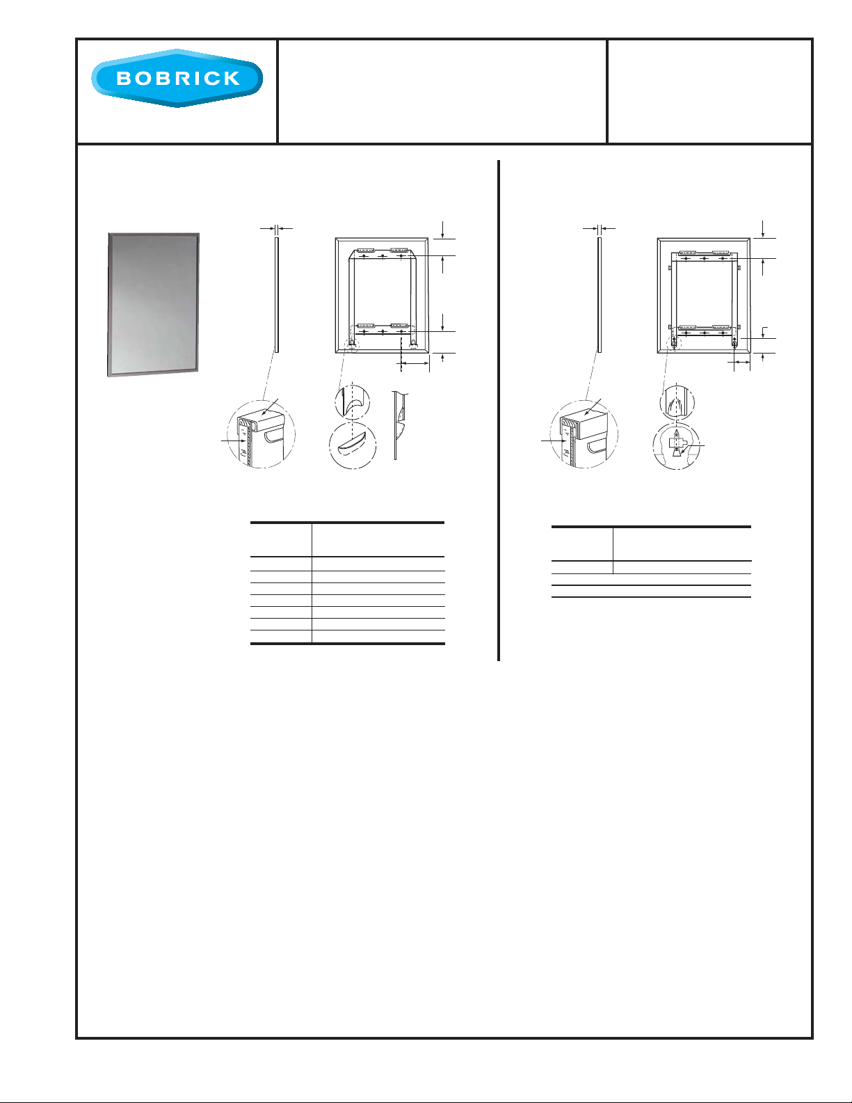
MIRROR WITH
STAINLESS STEEL
CHANNEL FRAME
B-165
SERIES
SNAP LOCKING DESIGN
(Rear View)
1/2''
Mirror
13mm
Frame
4'' or 5" Typ.
100 or 125mm
Back Plate/Wall Hanger
S
Side View
2-1/2''
65mm
2-9/16''
65mm
S
S
Mirror
Figure: 1 Figure: 2
STANDARD B-165 SERIES MIRRORS
MODEL
NO.
B-165 1824 18'' (46cm) 24'' (61cm)
B-165 1830 18'' (46cm) 30'' (76cm)
B-165 1836 18'' (46cm) 36'' (91cm)
B-165 2430 24'' (61cm) 30'' (76cm)
B-165 2436 24'' (61cm) 36'' (91cm)
B-165 2448 24'' (61cm) 48'' (122cm)
B-165 2460 24'' (61cm) 60'' (152cm)
OVERALL SIZE
W
H
SCREW LOCKING DESIGN
(Rear View)
1/2''
13mm
3"
75mm
T
Frame
Locking Screw
(Phillips-Head)
STANDARD B-165 SERIES MIRRORS
MODEL
NO.
B-165 4836 48'' (122cm) 36'' (91cm)
All Other Size Mirrors
OVERALL SIZE
HW
2-1/16''
50mm
S
1-13/16''
45mm
S
S
Designer's Notes:
1. Special-order sizes available on request.
2. Maximum size mirror available, 72'' x 60'' (183 x 152cm); minimum size, 12" x 12" (30 x 30cm).
3. All Bobrick framed mirrors are manufactured to overall width and height dimensions. EXAMPLE: A 24" x 36'' (61 x 91cm) mir ror will be furnished 24'' x
36'' (61 x 91cm) outside-of-frame to outside-of-frame.
4. To specify special sizes use Series Number followed by width then height in inches. EXAMPLE: B-165 2024.
5. Bobrick framed mirrors are manufactured to a tolerance 1/8'' (3.2mm).
6. For sufficient space to lift mirror onto wall hanger(s), provide 3-1/4'' (85mm) minimum clearance above center line of mounting screw holes.
7. Provide 1'' (25mm) minimum clearance at bottom of mirror for engaging locking screws and 1'' (25mm) clearance on each side.
MATERIALS:
Frame — Type-430 stainless steel, 1/2" x 1/2" x 3/8" (13 x 13 x 9.5mm) channel with 1/4" (6mm) return at rear with bright
polished finish. One piece frame with 90 degree mitered corners. Galvanized steel back has integral horizontal hanging brackets near the top for hanging the mirror and near the bottom to prevent the bottom of the mirror from pulling away from the
wall. Locking devices secure mirror to concealed wall hanger. In Screw Locking Design (see figure 2), concealed Philips-head
locking screws securely fasten mirror to wall hanger.
Mirror — No. 1 quality, 1/4" (6mm) select float glass: selected for silvering, electrolytically copper-plated by the galvanic
process, and guaranteed for 15 years against silver spoilage. Corners are protected by friction-absorbing filler strips; back is
protected by full-size, shock-absorbing, water-resistant, nonabrasive, 3/16" (5mm) thick polyethylene padding.
Concealed Wall Hanger — 20-gauge (0.9mm) galvanized steel. Incorporates lower support member, forming rigid rectangle,
which engages lower backplate louvers to keep bottom of mirror against wall.
continued . . .
The illustrations and descriptions herein are applicable to production as of the date of this Technical Data Sheet. Rev. 2/2/11
The manufacturer reserves the right to, and does from time to time, make changes and improvements in designs and dimensions. © 2011 by Bobrick Washroom Equipment, Inc.
R/B
Printed in U.S.A.
Page 2
INSTALLATION:
Mount wall hanger on wall with screws (not furnished) at points indicated by an S. For plaster or dr y wall construction,
provide backing to comply with local building codes, then secure wall hanger with screws (not furnished) . When providing
a concealed backing, allow backing to cover minimum range of mounting hole locations shown on drawing. For other wall
surfaces, provide fiber plugs or expansion shields for use with screws (not furnished), or provide 1/8" (3mm) toggle bolts or
expansion bolts. Hang mirror on wall hanger with all four backplate louvers engaged behind horizontal wall hanger members.
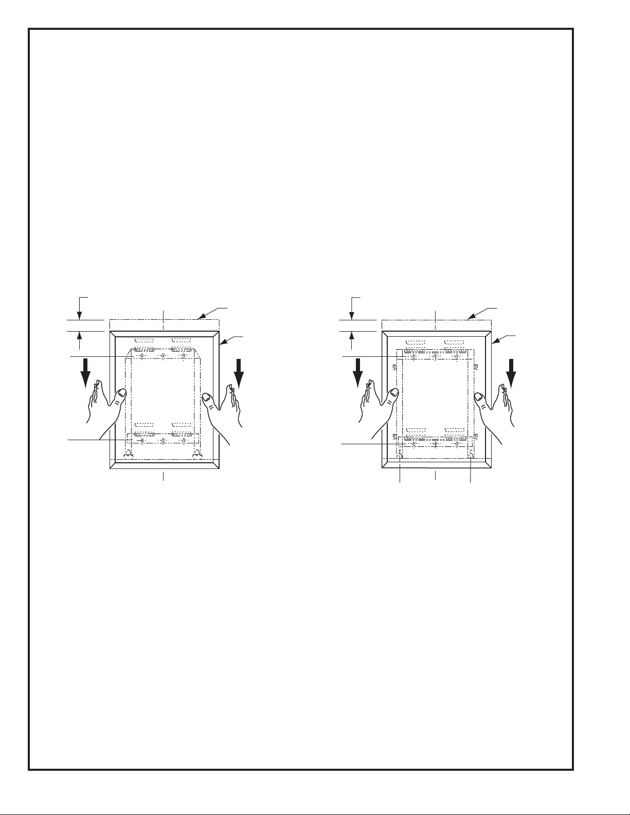
Hang mirror on wall hanger with all four backplate louvers engaged behind horizontal wall hanger members. To do this,
mirror must be centered in front of the wall hanger horizontally, pressed flat against the wall approximately 1" (25mm) above
final position and then lowered into final position.
Snap Locking Design — Locking devices automatically secure mirror to concealed wall hanger when it is lowered into final
position. Locking devices may be unlocked by inserting two flat blade screwdrivers behind each side of mirror near the bottom
or under the bottom of the mirror and pulling mirror bottom forward and then up (see figure 3).
Screw Locking Design — Lock mirror to wall hanger by tightening Phillips-head locking screws that are concealed in the
bottom of frame at points indicated by a T. Mirror may be unlocked from wall hanger by loosening locking screws and lifting
mirror of f of concealed wall hanger (see figure 4).
S
S
SNAP LOCKING DESIGN
(Front View)
Approx. 1"
(25mm)
C
L
Initial
Position
Final
Position
S
S
SCREW LOCKING DESIGN
(Front View)
Approx. 1"
(25mm)
T
C
L
Initial
Position
Final
Position
T
Figure: 3 Figure: 4
SPECIFICATION:
Mirror shall have a one-piece type-430 stainless steel channel frame, 1/2" x 1/2" x 3/8" (13 x 13 x 9.5mm), with 90° mitered
corners; all exposed surfaces shall have bright polished finish. Select float glass mirror shall be guaranteed for 15 years against
silver spoilage. Corners shall be protected by friction-absorbing filler strips and the back shall be protected by full-size, shockabsorbing, water-resis tant, nonabrasive, 3/16" (5mm) thick polyethylene padding. Galvanized steel back shall have integral
horizontal hanging brackets located at top and bottom for mounting on concealed rectangular wall hanger to prevent the mirror
from pulling away from the wall. Locking devices secure mirror to concealed wall hanger. Mirror shall be removable from the
wall.
Framed Mirror shall be Model B-165 _______________ (inser t width and height) of Bobrick Washroom Equipment,
Inc., Clifton Park, New York; Jackson, Tennessee; Los Angeles, California; Bobrick Washroom Equipment
Company, Scarborough, Ontario; Bobrick Washroom Equipment Pty. Ltd., Australia; and Bobrick Washroom
Equipment Limited, United Kingdom.
R/B
The illustrations and descriptions herein are applicable to production as of the date of this Technical Data Sheet. B-165 Rev. 2/2/11
The manufacturer reserves the right to, and does from time to time, make changes and improvements in designs and dimensions. © 2011 by Bobrick Washroom Equipment, Inc.
QA020211
Printed in U.S.A.
 Loading...