

Page 1

116655BB
➤
OOwwnneerr’’ss//IInnssttaallllaattiioonn GGuuiiddee
Page 2

i
© 2005 Directed Electronics, Inc.
lliimmiitteedd lliiffeettiimmee ccoonnssuummeerr wwaarrrraannttyy
Directed Electronics, Inc. (hereinafter "Directed") promises to the original purchaser to
repair or replace with a comparable reconditioned Directed DIY remote start unit if this
Directed DIY remote start unit (hereinafter "Unit"), excluding without limitation, any
remote transmitters or associated accessories, proves defective in materials or workmanship under normal use for the life of the vehicle which the Unit is originally installed.
During this period, so long as the Unit remained installed in the original vehicle, Directed
will at its option, repair or replace this Unit if it is proved defective in workmanship or
material PROVIDED the Unit is returned to Directed's warranty department at One
Viper Way, Vista, CA 92081, along with $20 postage and handling fee, a bill of sale or
other dated proof of purchase bearing the following information: Date of purchase, name
and location of the merchant who sold the Unit, and product description. This warranty
does not cover labor costs for the removal or reinstallation of the Unit. This warranty is
non-transferable and does not apply to any Unit that has been modified or used in a manner contrary to its intended purpose, and this warranty does not cover damage to any Unit
caused by installation or removal of the Unit. This warranty is void if the Unit has been
damaged by accident or unreasonable use, neglect, improper service or other causes not
arising out of defects in materials or workmanship. Directed makes no warranty against
theft of a vehicle or its contents.
THE FOREGOING WARRANTY IS THE EXCLUSIVE PRODUCT WARRANTY,
OTHERWISE, ALL WARRANTIES INCLUDING BUT NOT LIMITED TO
EXPRESS WARRANTY, IMPLIED WARRANTY, WARRANTY OF MERCHANTABILITY, OR FITNESS FOR A PARTICULAR PURPOSE ARE EXPRESSLY
EXCLUDED AND DISCLAIMED TO THE MAXIMUM EXTENT ALLOWED BY
LAW, AND DIRECTED NEITHER ASSUMES NOR AUTHORIZES ANY PERSON
TO ASSUME FOR IT ANY LIABILITY IN CONNECTION WITH THE SALE OF
THE PRODUCT. DIRECTED HAS ABSOLUTELY NO LIABILITY FOR ANY
AND ALL ACTS OF THIRD PARTIES INCLUDING ITS AUTHORIZED DEALERS OR INSTALLERS. SOME STATES DO NOT ALLOW THE LIMITATION ON
HOW LONG AN IMPLIED WARRANTY LASTS, SO THE ABOVE LIMITATION
MAY NOT APPLY TO YOU.
LIMITATION OF DAMAGES AND LIABILITY. CONSUMER'S REMEDY IS LIMITED TO REPAIR OR REPLACEMENT OF THE UNIT, AND IN NO EVENT
SHALL DIRECTED'S LIABILITY EXCEED THE PURCHASE PRICE OF THE
UNIT. IN ANY EVENT, DIRECTED SHALL NOT BE LIABLE FOR ANY DAMAGES INCLUDING, BUT NOT LIMITED TO, ANY DIRECT, INDIRECT, INCIDENTAL, SPECIAL, PUNITIVE OR CONSEQUENTIAL DAMAGES, LOST
PROFITS, LOST SAVINGS, OR, TO THE EXTENT ALLOWED BY APPLICABLE
LAW, DAMAGES RESULTING FROM DEATH OR INJURY ARISING OUT OF
Page 3

ii
© 2005 Directed Electronics, Inc.
OR IN CONNECTION WITH THE INSTALLATION, USE, IMPROPER USE, OR
INABILITY TO USE, THE PRODUCT, EVEN IF THE PARTY HAS BEEN
ADVISED OF THE POSSIBILITY OF SUCH DAMAGES. SOME STATES DO
NOT ALLOW THE EXCLUSION OF LIMITATION OF INCIDENTAL OR CONSEQUENTIAL DAMAGES, SO THE ABOVE LIMITATIONS OR EXCLUSION
MAY NOT APPLY TO YOU. THE CONSUMER AGREES AND CONSENTS THAT
ALL DISPUTES BETWEEN THE CONSUMER AND DIRECTED SHALL BE
RESOLVED IN ACCORDANCE WITH CALIFORNIA LAWS IN SAN DIEGO
COUNTY, CALIFORNIA.
IIMMPPOORRTTAANNTT NNOOTTEE::
This product warranty is automatically void if its date code or serial number is defaced,
missing, or altered.
Make sure you have all of the following information from your dealer:
A clear copy of the sales receipt, showing the following:
➤ Date of purchase
➤ Authorized dealer's company name and address
➤ Item number
Page 4

1
© 2005 Directed Electronics, Inc.
ttaabbllee ooff ccoonntteennttss
lliimmiitteedd lliiffeettiimmee ccoonnssuummeerr wwaarrrraannttyy.. .. .. .. .. .. .. .. .. .. .. .. .. .. .. .. .. .. .. .. .. .. .. .. .. .. .. .. .. .. .. .. .. .. .. .. .. .. .. .. ii
wwhhaatt iiss iinncclluuddeedd .. .. .. .. .. .. .. .. .. .. .. .. .. .. .. .. .. .. .. .. .. .. .. .. .. .. .. .. .. .. .. .. .. .. .
. .. .. .. .. .. .. .. .. .. .. .. .. .. .. .. .. .. .. .. 33
iinnssttaallllaattiioonn ttoooollss.. .. .. .. .. .. .. .. .. .. .. .. .. .. .. .. .. .. .. .. .
. .. .. .. .. .. .. .. .. .. .. .. .. .. .. .. .. .. .. .. .. .. .. .. .. .. .. .. .. .. .. .. .. .. 33
iimmppoorrttaanntt iinnffoorrmmaattiioonn .. .. .. .. ..
.. .. .. .. .. .. .. .. .. .. .. .. .. .. .. .. .. .. .. .. .. .. .. .. .. .. .. .. .. .. .. .. .. .. .. .. .. .. .. .. .. .. .. .. 44
system maintenance . . . . . . . . . . . . . . . . . . . . . . . . . . . . . . . . . . . . . . . . . . . . . . 4
fcc/id notice . . . . . . . . . . . . . . . . . . . . . . . . . . . . . . . . . . . . . . . . . . . . . . . . . . . . 5
wwaarrnniinngg!
! ssaaffeettyy ffiirrsstt .. .. .. .. .. .. .. .. .. .. .. .. .. .. .. .. .. .. .. .. .. .. .. .. .. .. .. .. .. .. .. .. .. .. .. .. .. .. .. .. .. .. .. .. .. .. .. .. .. .. .. 55
pprriimmaarryy hhaarrnneessss ((HH//11)),,88--ppiinn ccoonnnneeccttoorr .. .. .. .. .. .. .. .. .. .. .. .. .. .. .. .. .. .. .. .. .. .. ..
.. .. .. .. .. .. .. .. .. .. .. .. .. 88
rreellaayy wwiirreess 66--ccoonnnneeccttoorrss .. .. .. .. .. .. .. .. .. .. .. .. .. .. .. .. .. .. .. .. .. .. .. ..
.. .. .. .. .. .. .. .. .. .. .. .. .. .. .. .. .. .. .. .. .. .. .. .. 99
uussiinngg LLEEDD tteesstt pprroobbee .. .. .. .. .. .. .. .. .. .. .. .. .. .. ..
.. .. .. .. .. .. .. .. .. .. .. .. .. .. .. .. .. .. .. .. .. .. .. .. .. .. .. .. .. .. .. .. .. .. 1100
iinnssttaallllaattiioonn .. .. .. .. .. .. .. .. .
. .. .. .. .. .. .. .. .. .. .. .. .. .. .. .. .. .. .. .. .. .. .. .. .. .. .. .. .. .. .. .. .. .. .. .. .. .. .. .. .. .. .. .. .. .. .. .. .. 1111
w
wiirriinngg qquuiicckk rreeffeerreennccee gguuiiddee .. .. .. .. .. .. .. .. .. .. .. .. .. .. .. .. .. .. .. .. .. .. .. .. .. .. .. .. .. .. .. .. .. .. .. .. .. .. .. .. .. .. .. 1122
step 1 . . . . . . . . . . . . . . . . . . . . . . . . . . . . . . . . . . . . . . . . . . . . . . . . . . . . . . . . 13
step 2 . . . . . . . . . . . . . . . . . . . . . . . . . . . . . . . . . . . . . . . . . . . . . . . . . . . . . . . . 14
step 3 . . . . . . . . . . . . . . . . . . . . . . . . . . . . . . . . . . . . . . . . . . . . . . . . . . . . . . . . 16
step 4 . . . . . . . . . . . . . . . . . . . . . . . . . . . . . . . . . . . . . . . . . . . . . . . . . . . . . . . . 19
step 5 . . . . . . . . . . . . . . . . . . . . . . . . . . . . . . . . . . . . . . . . . . . . . . . . . . . . . . . . 22
step 6 . . . . . . . . . . . . . . . . . . . . . . . . . . . . . . . . . . . . . . . . . . . . . . . . . . . . . . . . 24
step 7 . . . . . . . . . . . . . . . . . . . . . . . . . . . . . . . . . . . . . . . . . . . . . . . . . . . . . . . . 27
step 8 . . . . . . . . . . . . . . . . . . . . . . . . . . . . . . . . . . . . . . . . . . . . . . . . . . . . . . . . 28
step 9 . . . . . . . . . . . . . . . . . . . . . . . . . . . . . . . . . . . . . . . . . . . . . . . . . . . . . . . . 29
step 10 . . . . . . . . . . . . . . . . . . . . . . . . . . . . . . . . . . . . . . . . . . . . . . . . . . . . . . . 30
ttrraannssmmiitttteerr ffuunnccttiioonnss .. .. .. .. .. .. .. .. .. .. .. .. .. .. .. .. .. .. .. .. .. .. .. .. .. .. .. .. .. .. .
. .. .. .. .. .. .. .. .. .. .. .. .. .. .. .. .. .. .. 3311
standard configuration . . . . . . . . . . . . . . . . . . . . . . . . . . . . . . . . . . . . . . . . . . . 31
CCoonnttrrooll MMoodduullee PPrrooggrraammmmiinngg .. .. .. .. .. .. .. .. .. .. .. .. .. .. .. .. .
. .. .. .. .. .. .. .. .. .. .. .. .. .. .. .. .. .. .. .. .. .. .. .. .. 3322
uussiinngg yyoouurr ssyysstteemm .. .. .. .. .. .. .. .. .. .. .. .. .. .. .. .
. .. .. .. .. .. .. .. .. .. .. .. .. .. .. .. .. .. .. .. .. .. .. .. .. .. .. .. .. .. .. .. .. .. .. .. 3333
warning! safety first . . . . . . . . . . . . . . . . . . . . . . . . . . . . . . . . . . . . . . . . . . . . . . 33
remote start . . . . . . . . . . . . . . . . . . . . . . . . . . . . . . . . . . . . . . . . . . . . . . . . . . . 35
timer mode . . . . . . . . . . . . . . . . . . . . . . . . . . . . . . . . . . . . . . . . . . . . . . . . . . . . 36
ppiitt ssttoopp mmooddee.. .. .. .. .. .
. .. .. .. .. .. .. .. .. .. .. .. .. .. .. .. .. .. .. .. .. .. .. .. .. .. .. .. .. .. .. .. .. .. .. .. .. .. .. .. .. .. .. .. .. .. .. .. .. .. 3
388
ccooddee hhooppppiinngg ®® rree--ssyynncchhrroonniizzee .. .. .. .. .. .. .. .. .. .. .. .. .. .. .. .. .. .. .. .. .. .. .. .. .. .. .. .. .. .. .. .. .. .. .
. .. .. .. .. .. .. 3388
ttrroouubblleesshhoooottiinngg .. .. .. .. .. .. .. .. .. .. .. .. .. .. .. .. .. .. .. .. .. .. .. .. .. .. .. .. .. .. .. .. .. .. .
. .. .. .. .. .. .. .. .. .. .. .. .. .. .. .. .. .. .. 3399
gglloossssaarryy ooff tteerrmmss .. .. .. .. .. .. .. .. .. .. .. .. .. .. .. .. .. .. .. .. .. .
. .. .. .. .. .. .. .. .. .. .. .. .. .. .. .. .. .. .. .. .. .. .. .. .. .. .. .. .. .. .. 4411
nnootteess .. .. .. .. .. .. .. .. .. .. .. .. .. .. .. .
. .. .. .. .. .. .. .. .. .. .. .. .. .. .. .. .. .. .. .. .. .. .. .. .. .. .. .. .. .. .. .. .. .. .. .. .. .. .. .. .. .. .. .. .. .. 4422
qquuiicckk
rreeffeerreennccee gguuiiddee .. .. .. .. .. .. .. .. .. .. .. .. .. .. .. .. .. .. .. .. .. .. .. .. .. .. .. .. .. .. .. .. .. .. .. .. .. .. .. .. .. .. .. .. .. .. .. .. .. 4455
Page 5

2
© 2005 Directed Electronics, Inc.
Page 6
3
© 2005 Directed Electronics, Inc.
wwhhaatt iiss iinncclluuddeedd
➤ Control Module
➤ One 4-Button Transmitter
➤ 8-Pin Main H/1 Harness
➤ 6-Relay Wires
➤ Shutdown Toggle Switch
➤ Hood Pin Switch
➤ 10 feet of Black Electrical Tape
➤ 6 Six inch Zip Ties
➤ LED Tester
➤ Razor Knife
➤ CDROM—Do-It-Yourself Installation Video
Additional parts may be required (such as relays or immobilizer).
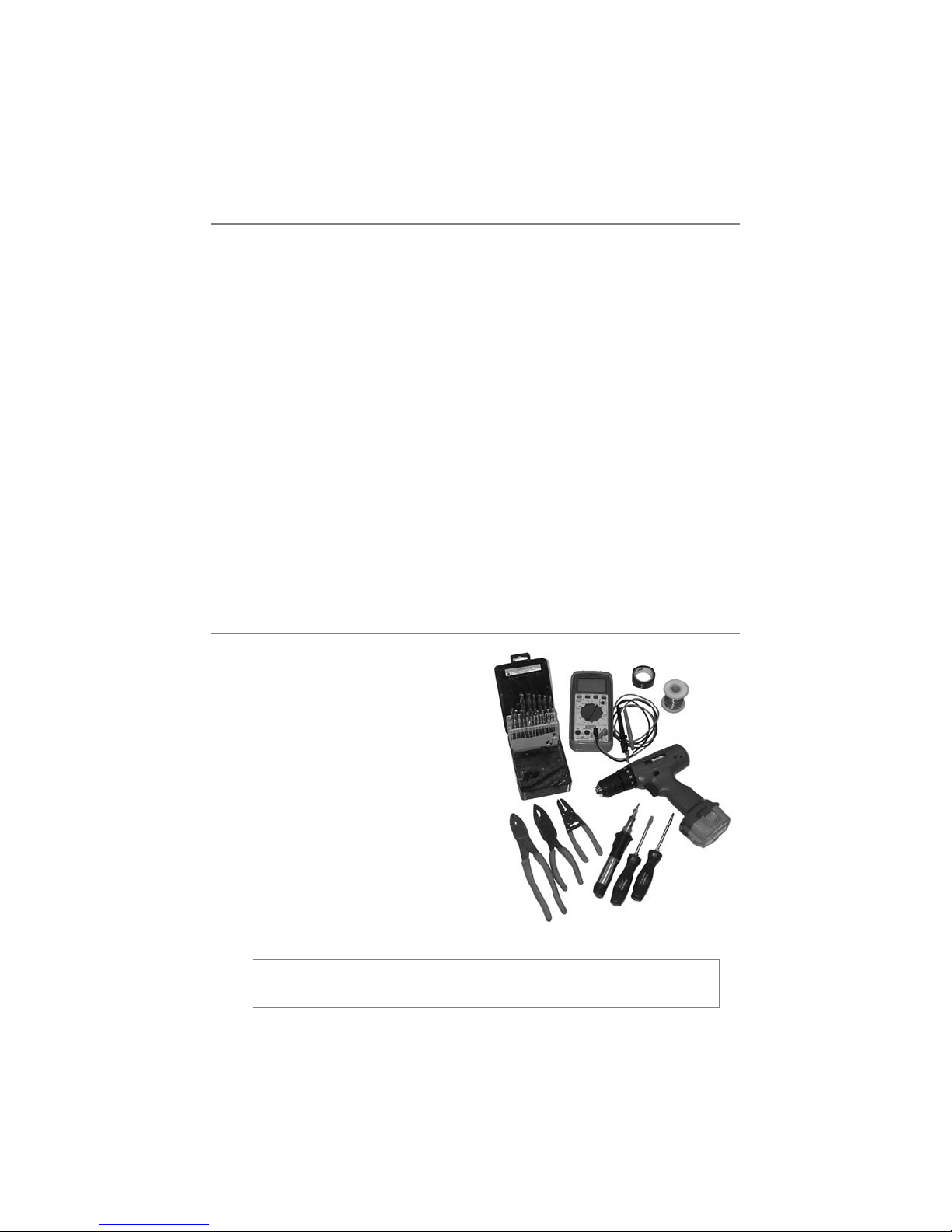
iinnssttaallllaattiioonn ttoooollss
➤ Digital Multi-Meter
➤ Drill
➤
9
/
32 and
5
/
16 Drill Bits
➤ Screwdrivers
(Phillips and Flathead)
➤ Wire Stripper
➤ Solder Iron
➤ Electrical Tape
➤ Pliers
➤ Crimping Tool
note: The installation tools listed above may be optional
and those required will vary depending on your vehicle.
Page 7

4
© 2005 Directed Electronics, Inc.
iimmppoorrttaanntt iinnffoorrmmaattiioonn
Congratulations on the purchase of your remote start system. This
system will allow convenient remote start of your vehicle. Properly
installed, this system will provide years of trouble-free operation.
Please take the time to carefully read this User’s Guide in its
entirety and watch the Do-It-Yourself Installation Video
(CDROM) prior to installing your system.
You can print additional or replacement copies of this manual by
accessing the Directed web site at www.boasecurity.com.
system maintenance
The system requires no specific maintenance. Your transmitter is
powered by a miniature 3-volt battery (type CR2032) that will
last approximately one year under normal use. When the battery
begins to weaken, the operating range will be reduced.
➜
important! If you are not comfortable working with electronics or unfamiliar with the tools required, please contact your local dealer for advice or ask to have the remote
start professionally installed to avoid costly damages.
Failure to properly install the remote starter may result in
property damage, personal injury, or both.
Page 8

5
© 2005 Directed Electronics, Inc.
fcc/id notice
This device complies with Part 15 of FCC rules. Operation is
subject to the following conditions: (1) This device may not
cause harmful interference, and (2) This device must accept any
interference received, including interference that may cause
undesirable operation.
Changes or modifications not expressly approved by the party
responsible for compliance could void the user's authority to
operate this device.
wwaarrnniinngg!! ssaaffeettyy ffiirrsstt
The following safety warnings must be observed at all times:
➤ When properly installed, this system can start the vehicle via
a command signal from the remote control transmitter.
Therefore, never operate the system in an area that does not
have adequate ventilation. The following precautions are the
sole responsibility of the user; however, the following recom-
mendations should be made to all users of this system:
1. Never operate the system in an enclosed or partially
enclosed area without ventilation (such as a garage).
2. When parking in an enclosed or partially enclosed area
or when having the vehicle serviced, the remote start
system must be disabled using the toggle switch.
3. It is the user's sole responsibility to properly handle and
keep out of reach from children all remote control
➜
Page 9

6
© 2005 Directed Electronics, Inc.
transmitters to assure that the system does not uninten-
tionally remote start the vehicle.
4.
TTHHEE UUSSEERR MMUUSSTT IINNSSTTAALLLL AA CCAARRBBOONN
MMOONNOOXXIIDDEE DDEETTEECCTTOORR IINN OORR AABBOOUUTT TTHHEE
LLIIVVIINNGG AARREEAA AADDJJAACCEENNTT TTOO TTHHEE VVEEHHI
ICCLLEE..
AALLLL DDOOOORRSS LLEEAADDIINNGG FFRROOMM AADDJJAACCEENNTT
LLIIVVIINNGG AARREEAASS TTOO TTHHEE EENNCCLLOOSSEEDD OORR
PPAARRTTIIAALLLLYY EENNCCLLOOSSEEDD VVEEHHIICCLLEE SSTTOOR
RAAGGEE
AARREEAA MMUUSSTT AATT AALLLL TTIIMMEESS RREEMMAAIINN CCLLOOSSEEDD..
➤ Use of this product in a manner contrary to its intended
mode of operation may result in property damage, personal
injury, or death. Except when performing the Safety Check
outlined in this user’s guide, (1) Never remotely start the
vehicle with the vehicle in gear, and (2) Never remotely start
the vehicle with the keys in the ignition. The user will be
responsible for having the neutral safety feature of the vehicle
periodically checked, wherein the vehicle must not remotely
start while the car is in gear. This testing should be performed
by an authorized Directed dealer in accordance with the
Safety Check outlined in this product installation guide. If the
vehicle starts in gear, cease remote start operation immediately
and consult with the Dealer to fix the problem immediately.
➤ After the remote start module has been installed, test the
remote start module in accordance with the Safety Check
outlined in this installation guide. If the vehicle starts when
performing the Neutral Safety Shutdown Circuit test, the
remote start unit has not been properly installed. The remote
Page 10

7
© 2005 Directed Electronics, Inc.
start module must be removed or properly reinstalled so that
the vehicle does not start in gear.
OOPPEERRAATTIIOONN OOFF TTHHEE
RREEMMOOTTEE SSTTAARRTT MMOODDUULLEE IIFF TTHHEE VVEEHHIICCLLEE
SSTTAARRTTSS IINN GGEEAARR IISS CCOONNTTRRAARRYY TTOO IITTSS IINNTTEENNDDEEDD
MMOOD
DEE OOFF OOPPEERRAATTIIOONN.. OOPPEERRAATTIINNGG TTHHEE
RREEMMOOTTEE SSTTAARRTT SSYYSSTTEEMM UUNNDDEERR TTHHEESSEE CCOONNDDII--
TTIIOONNSS MMAAYY RREESSUULLTT IINN PPRROOPPEERRTTYY DDA
AMMAAGGEE OORR
PPEERRSSOONNAALL IINNJJUURRYY.. IIMMMMEEDDIIAATTEELLYY CCEEAASSEE TTHHEE
UUSSEE OOFF TTHHEE UUNNIITT AANNDD RREEPPAAIIRR OORR DDIISSCCOONNNNEECCTT
TTHHEE IINNSSTTAALLLLE
EDD RREEMMOOTTEE SSTTAARRTT MMOODDUULLEE..
DDIIRREECCTTEEDD WWIILLLL NNOOTT BBEE HHEELLDD RREESSPPOONNSSIIBBLLEE OORR
PPAAYY FFOORR IINNSSTTAALLLLAATTIIOONN OORR RREEIINNSSTTAALLLLAATTIIO
ONN
CCOOSSTTSS..
Page 11
8
© 2005 Directed Electronics, Inc.
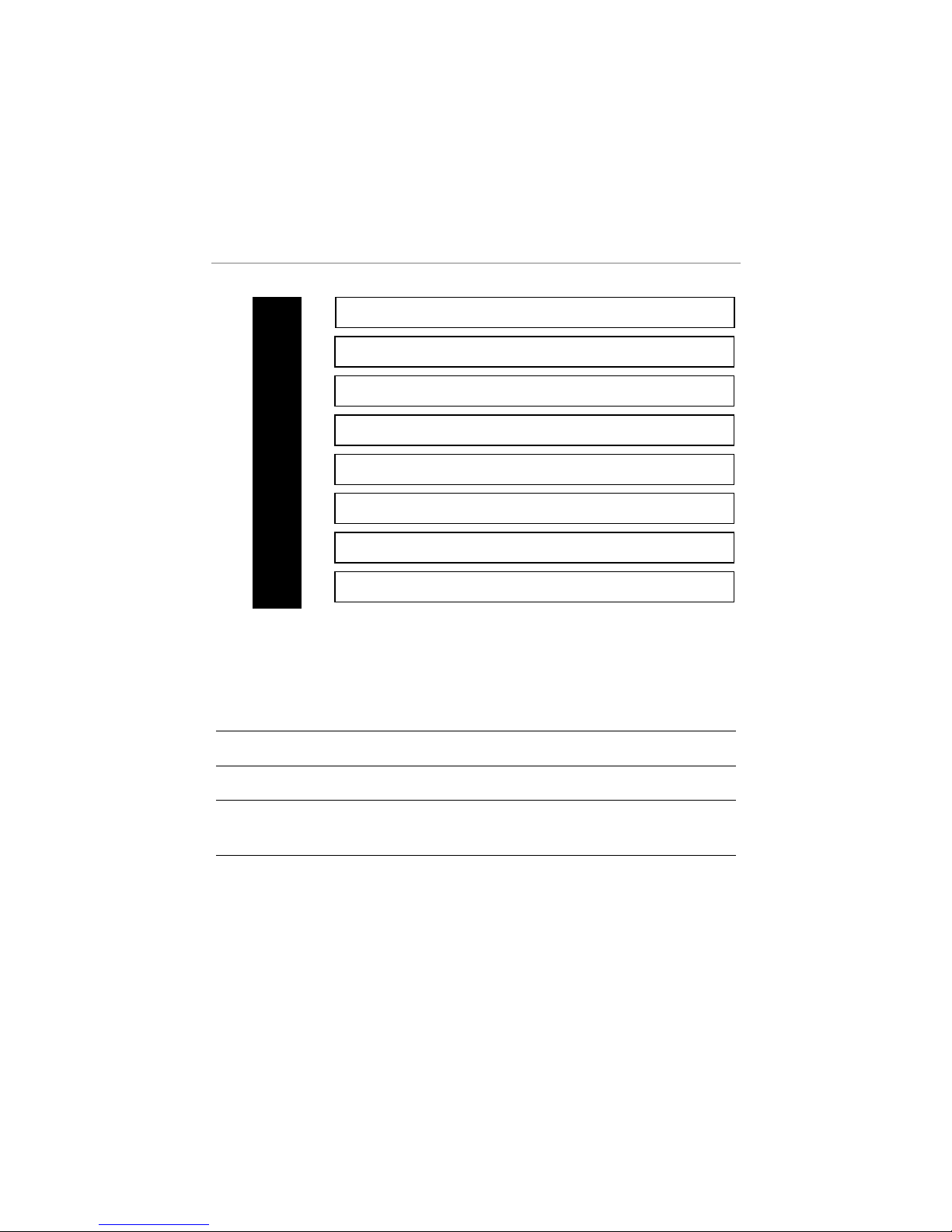
pprriimmaarryy hhaarrnneessss ((HH//11)),,
88--ppiinn ccoonnnneeccttoorr
___
___
___
___
___
___
___
___
Use the following wiring guidelines for the H1 harness.
PPiinn ## WWiirree CCoolloorr NNoottee
H1/1 Blue Only required when using a bypass module.
H1/3 Brown This wire
mmuusstt
be connected.
H1/6 White/Blue
Not required unless tying into an existing
system.
H1/7
Lt. Green/
Black
Use if the vehicle is equipped with a factory
alarm.
WHITE (-) Parking Light Flash Output (optional)
LT. GREEN/BLACK Factory Alarm Disarm
WHITE/BLUE (-) Remote Start Activation Input
BLACK Ground
GRAY (-) Hood Pin Shutdown Input
BROWN (+) Brake Switch Shutdown Input
VIOLET/WHITE Tachometer Input (optional)
BLUE (-) 200mA Status Output
HH11//11
HH11//22
HH11//33
HH11//44
HH11//55
HH11//66
HH11//77
HH11//88
Page 12
9
© 2005 Directed Electronics, Inc.
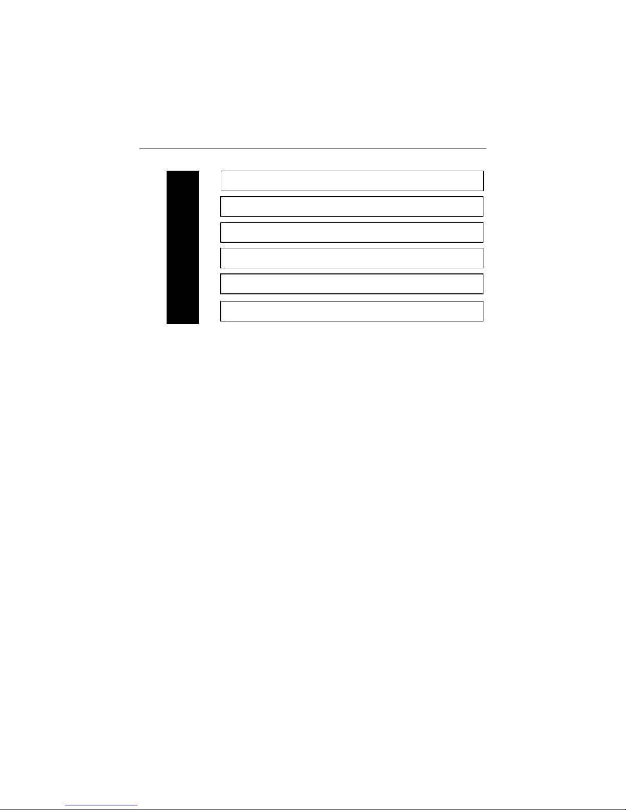
rreellaayy wwiirreess 66--ccoonnnneeccttoorrss
___
___
___
___
___
___
PINK/WHITE(+) Output to IGN2 Circuit
RED (+) (30A) High Current 12V Input
PINK (+) Output to IGN1 Circuit
ORANGE (+) Output to ACC1 Circuit
RED (+) (30A) High Current 12V Input
VIOLET (+) Output to Starter Circuit
HH11//11
HH11//22
HH11//33
HH11//44
HH11//55
HH11//66
Page 13

10
© 2005 Directed Electronics, Inc.
uussiinngg LLEEDD tteesstt pprroobbee
To use the LED test probe:
1. Remove the protective cover off the probe tip. Save the
protective cover for reinstallation on the probe tip when
the LED tester is not being used.
2. Connect the Black clip to a good chassis ground.
3. Connect the Red clip to a good +12V source. Both the
Red and Green LEDs should be illuminated dimly.
4. If a positive voltage source is probed, the Red LED will
illuminate brightly, and the Green LED will extinguish.
5. If a negative source is probed the Green LED will illu-
minate brightly and the Red LED will extinguish.
Alternate procedure to use the LED test probe (only for use on
probing positive voltage wires):
1. Remove the protective cover off the probe tip. Save the
protective cover for reinstallation on the probe tip when
the LED tester is not being used.
2. Connect the Black clip to a good chassis ground.
3. If a positive voltage source is probed, the Red LED will
illuminate brightly.
note: Do not use this test probe on computerized equipment as damage can result.
Page 14
11
© 2005 Directed Electronics, Inc.
iinnssttaallllaattiioonn
Be sure to read this section thoroughly and view the Do-ItYourself Installation CDROM video in its entirety before
starting the installation. Pay special attention to all warnings to
prevent personal injury or damage to your vehicle.
Visit our 24-hour technical Web site (
wwwwww..bbooaasseeccuurriittyy..ccoomm
)to
get a vehicle-specific wiring guide prior to starting this installation. Have on hand your crash code number when contacting
tech support or visiting the web site. If at any time during the
installation you are unable to answer your questions on the Web
site, call
11--880000--887733--11331144
for live technical assistance.
warning! Verify that the vehicle is set to
park and that the parking brake is set
before beginning installation.
warning! On vehicles with air bags or supplemental restraint systems (SRS) you may
notice a bright yellow tube with small wires
in it marked SRS underneath the steering
column near the key cylinder. DO NOT
tamper or unplug these for any reason to
prevent costly damages to your vehicle or
personal injury. Tampering may cause
unintended deployment of airbags.
warning! This system is intended for automatic, fuel-injected vehicles only. Installation
in any other vehicle is contrary to its intended use.
Page 15
12
© 2005 Directed Electronics, Inc.
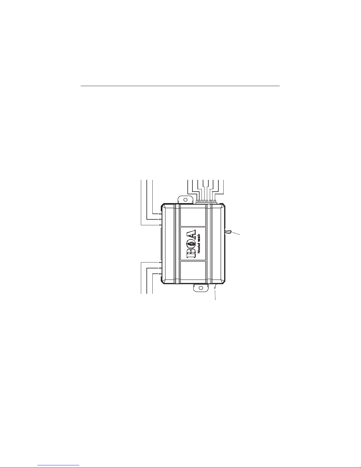
wwiirriinngg qquuiicckk rreeffeerreennccee gguuiiddee
PINK/WHITE (+) output to 2nd ignition
RED (+) 30A high current 12V input
PINK (+) output to ignition circuit
BLUE (-) 200 mA status output
GRAY (-) hood pin shutdown input
BLACK ground
WHITE/BLUE (-) remote start activation input
BROWN (+) brake switch shutdown input
VIOLET/WHITE tachometer input
LIGHT GREEN/BLACK factory alarm disarm
WHITE (-) parking light flash output
BLUE WIRE LOOP -
CUT FOR DIESEL VEHICLES
VIOLET (+) output to starter circuit
RED (+) 30A high current 12V input
ORANGE (+) 30A output to accessory circuit
ANTENNA
Page 16
13
© 2005 Directed Electronics, Inc.
step 1
Ground Wire
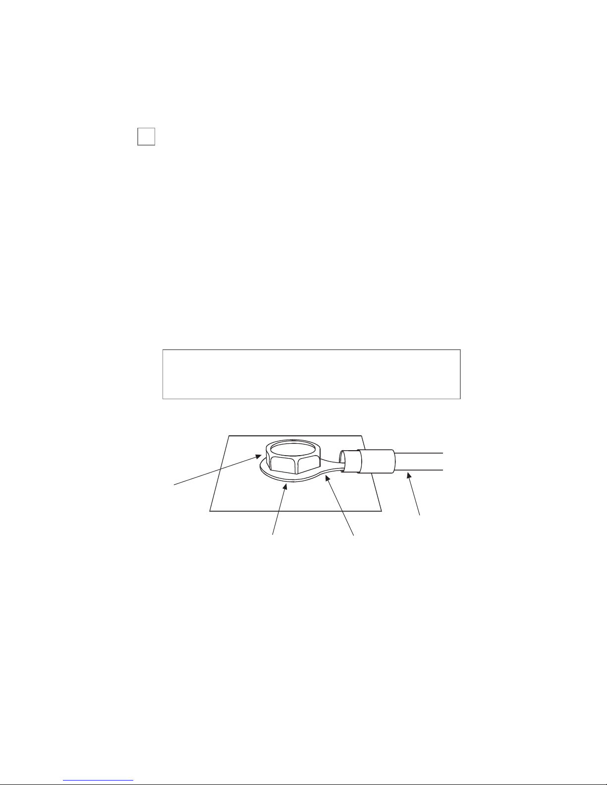
The BLACK (H1/5) wire on the main 8-pin harness is ground.
This wire should be connected to a clean, paint-free area of metal
only in the drivers kick panel area. First strip back a ¾-inch
section of the insulation off the BLACK wire and crimp a ring
terminal (not provided) to that wire. Locate a clean, paint-free
metal surface in the drivers kick panel. Using a self-tapping
screw, drill the screw with the ring terminal to the metal area.
Once screwed down, pull on the wire to ensure a good connec-
tion.
note: More problems are attributed to poor ground connections than any other cause. Take extra care to ensure
the ground is a clean metal-to-metal contact and secure.
➜
SELF-TAPPING
BOLT OR SCREW
DIA-591
NOTE: REMOVE ANY PAINT
BELOW RING CONNECTOR
GROUND
WIRE
RING
TERMINAL
Page 17
14
© 2005 Directed Electronics, Inc.
step 2
Constant Power and Ignition wires
Almost all power and ignition wires can be found behind the key
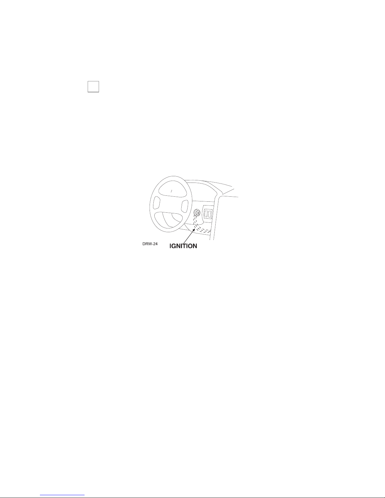
cylinder under the lower drivers side dash panel. Using the
appropriate hand tools, remove the lower dash panel using care
not to break any parts. If the panel does not come off easily
check for any additional screws you may have missed.
Once the lower dash panel has been removed, locate the ignition
harness at the back of the key cylinder. This is usually a group of
thicker wires. With the ignition harness exposed, use your LED
tester to find your power and ignition wires.
Place the black lead of the LED tester to a clean metal surface in
the kick panel area and secure it. Probe one of the thicker gauge
wires. The color and identity of your specific vehicle wiring can
be obtained at www.boasecurity.com. With the key in the OFF
position, test the suspect wire. The constant power wire will illu-
minate the LED tester.
➜
Page 18
15
© 2005 Directed Electronics, Inc.
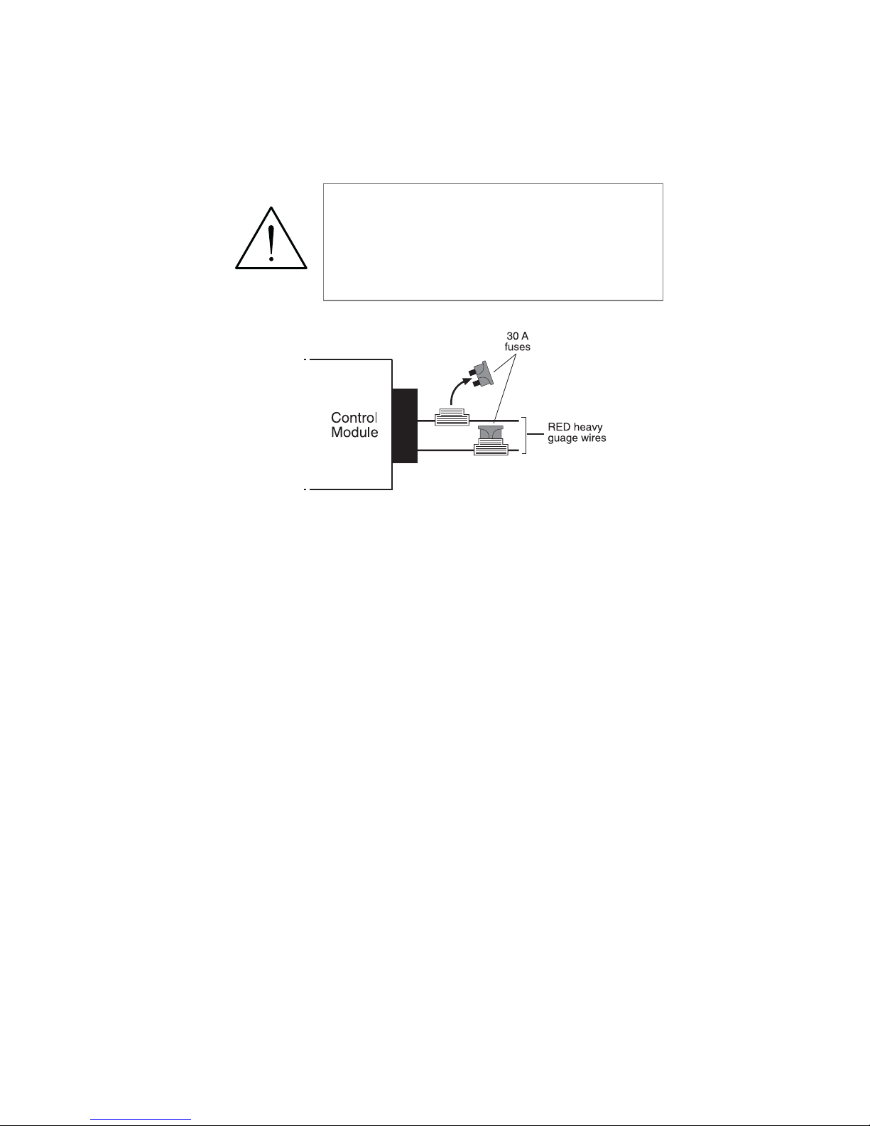
Once the constant power wire (or wires) has been identified, solder
the two thick RED wires from the control module to it and cover
the connection with electrical tape to ensure a safe connection.
With the black lead still in the kick panel, locate the ignition
wire harness in the same location. It will test differently than
constant (+)12 volts. Locate the suspected wire using the
www.boasecurity.com web site and then use the LED tester to
probe the suspected wire. With the key in the off position the
LED tester will not illuminate. Turn the key to the on position
and the LED tester will illuminate. Now while watching the
LED tester, turn the key to the crank position and the LED
tester should not extinguish. If the LED tester extinguishes this
is not an ignition wire but an accessory wire. If the wire tests
correctly, solder the PINK (C) relay wire to it and cover the
connection with electrical tape.
warning! Before making any connection
to constant battery power make sure that
the two green 30 amp fuses are removed
from the fuse holders on the two thick red
wires. Failure to do so may cause fire or
shorting of sensitive electrical components.
Page 19
16
© 2005 Directed Electronics, Inc.
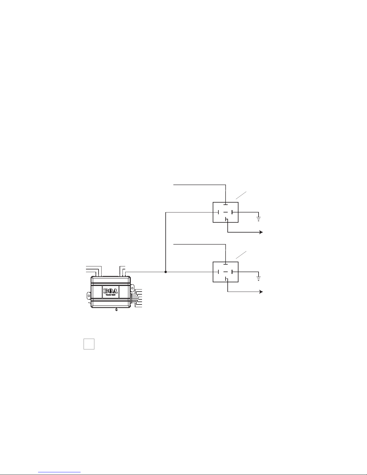
If the vehicle requires more than one ignition as per the Web site
information follow the same test procedure and solder the thick
PINK/WHITE (F) relay wire to it and be sure to wrap the
connection with electrical tape. If your vehicle has only 1 igni-
tion source, secure the PINK/WHITE out of the way.
If your vehicle requires more than two ignitions, an additional
relay (not provided) is required. Refer to the diagram below.
step 3
Accessory and Starter wires
The starter and accessory wires will be located in the same harness
as the ignition and constant power.
➜
+12 VDC CONSTANT (FUSED)
2nd IGNITION RELAY
(NOT PROVIDED)
PINK/WHITE (+) OUTPUT
TO 2nd IGNITION
TO 2nd IGNITION
86
+12 VDC CONSTANT (FUSED)
86
87
85
87A
30
nd
TO 2
87
85
87A
30
TO 3rd IGNITION
GROUND
IGNITION
3rd IGNITION RELAY
(NOT PROVIDED)
GROUND
Page 20
17
© 2005 Directed Electronics, Inc.
To find the accessory wire leave the LED tester black lead
connected to the metal ground, take the red lead and probe the
wire suspected to be the accessory. With the key off, your LED
tester should not illuminate. Turn the key to the on position and
the LED tester should be illuminated. Now turn the key to the
crank position. If you have the correct accessory wire the voltage
will disappear while the starter is cranking and return once the key
returns to the on position. If the wire tests correctly, strip the insu-
lation off a small portion and solder the thick ORANGE (C) relay
wire to it and wrap it with electrical tape.
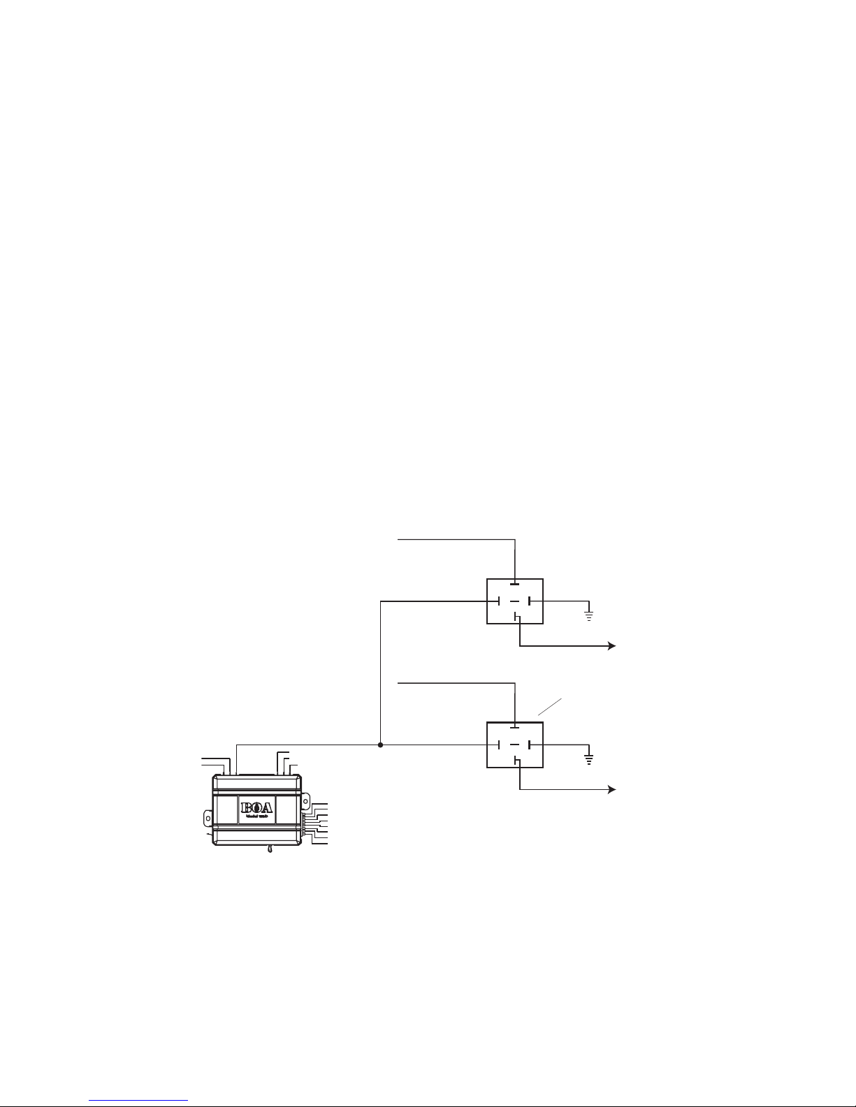
If your vehicle requires more than one accessory, an additional
relay (not provided) is required. Refer to the diagram below.
+12 VDC CONSTANT (FUSED)
TO ACCESSORY
87
86
87A
30
ACCESSORY RELAY
(NOT PROVIDED)
GROUND
85
+12 VDC CONSTANT (FUSED)
ORANGE (+) 30A OUTPUT TO
ACCESSORY CIRCUIT
86
TO ACCESSORY
87
GROUND
85
87A
30
TO 2nd ACCESSORY
2nd ACCESSORY RELAY
(NOT PROVIDED)
Page 21
18
© 2005 Directed Electronics, Inc.
Now that the accessories have been located, find the wire
suspected to be the starter wire according to the web information
on your vehicle. Place the red lead of your LED tester on the
wire. With the key in the off position the LED tester should be
extinguished in all key positions except the crank position. In
the crank position your LED tester should illuminate, and will
extinguish when the starter disengages.
Once you locate the starter wire, cut the wire in half (
cchheecckk tthhee wweebb
iinnffoorrmmaattiioonn bbeeffoorree ccuuttttiinngg
) and try to start the vehicle. If the vehicle
does not start, the correct wire has been identified. Reconnect both
ends of the starter wire while soldering the thick VIOLET (A) relay
wire to it and wrap the connection with electrical tape.
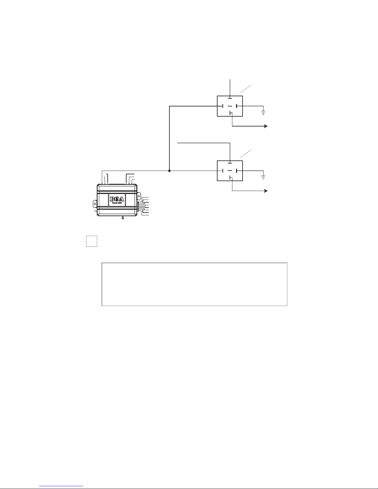
Many Nissan vehicles have two starter wires. A relay (not provided)
is required to hook up the additional starter wire. Refer to the
diagram below.
nnoottee::
Always check the Web site information on your
vehicle for warnings regarding the starter wire and check
engine lights. Some vehicles will trip a check engine light
if the starter wire is cut.
Page 22
19
© 2005 Directed Electronics, Inc.
step 4
Safety Shutdown Wires
With all ignition wires properly connected, find the appropriate
safety shutdown wires. These are the brake wire and hood pin wires.
First locate the factory brake wire using your LED tester. Find
the switch at the top of the metal arm coming off the brake
pedal. There are usually two wires connected to that switch.
Locate the wire color according to the web information. With
important! These wires are meant to protect the vehicle
and anyone near the vehicle. They must be connected
appropriately to prevent damage to the vehicle and possible bodily injury. Failure to properly install these wires may
cause the vehicle to lunge if remote started while in gear.
➜
STARTER RELAY
(NOT PROVIDED)
VIOLET (+) OUTPUT TO STARTER
TO STARTER
86
+12 VDC CONSTANT (FUSED)
86
87
85
87A
30
TO STARTER
87
85
87A
30
TO 2nd STARTER
GROUND
2nd STARTER RELAY
(NOT PROVIDED)
GROUND
Page 23
20
© 2005 Directed Electronics, Inc.
your black lead still in the kick panel, probe the suspected wire
with the red lead of the LED tester. With the brake pedal at rest
the LED tester should be extinguished. While watching the
tester, depress the brake pedal. The LED tester should illumi-
nate. Once you have located the correct brake wire, strip a small
portion of insulation off this wire and solder the small BROWN
(H1/3) wire on the main harness to it and wrap the connection
with electrical tape.
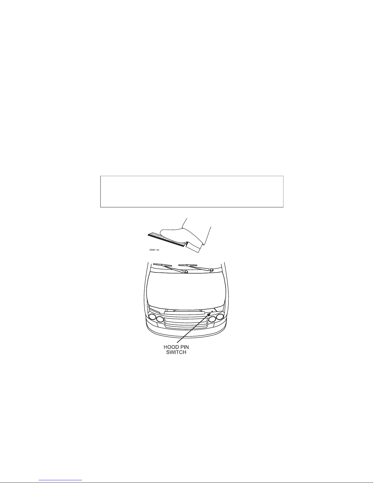
Installing the hood pin switch requires drilling a ¼-inch hole in the
metal lip under the hood. Choose a location that will allow the pin
switch to be depressed when the hood is closed. The pin switch has
a spade connector on the bottom for the wire connection.
important! This wire
MMUUSSTT
be connected Do not use
the vehicle until you confirm the operation of the brake
shutdown.
Page 24

21
© 2005 Directed Electronics, Inc.
Place the wire with the spade connector onto the pin switch and
run the wire into the vehicle’s passenger compartment through a
factory rubber grommet. Using a sharp, pointed object poke a
hole into the grommet and attach the wire to the object with
electrical tape. Pull the wire through the grommet taking extra
care to keep the wire away from any moving parts or anything
that will generate extreme heat. Once the wire is run into the
vehicle and secured from any moving parts, solder the wire to
the GRAY (H1/4) wire on the main wire connector and wrap
the connection with electrical tape.
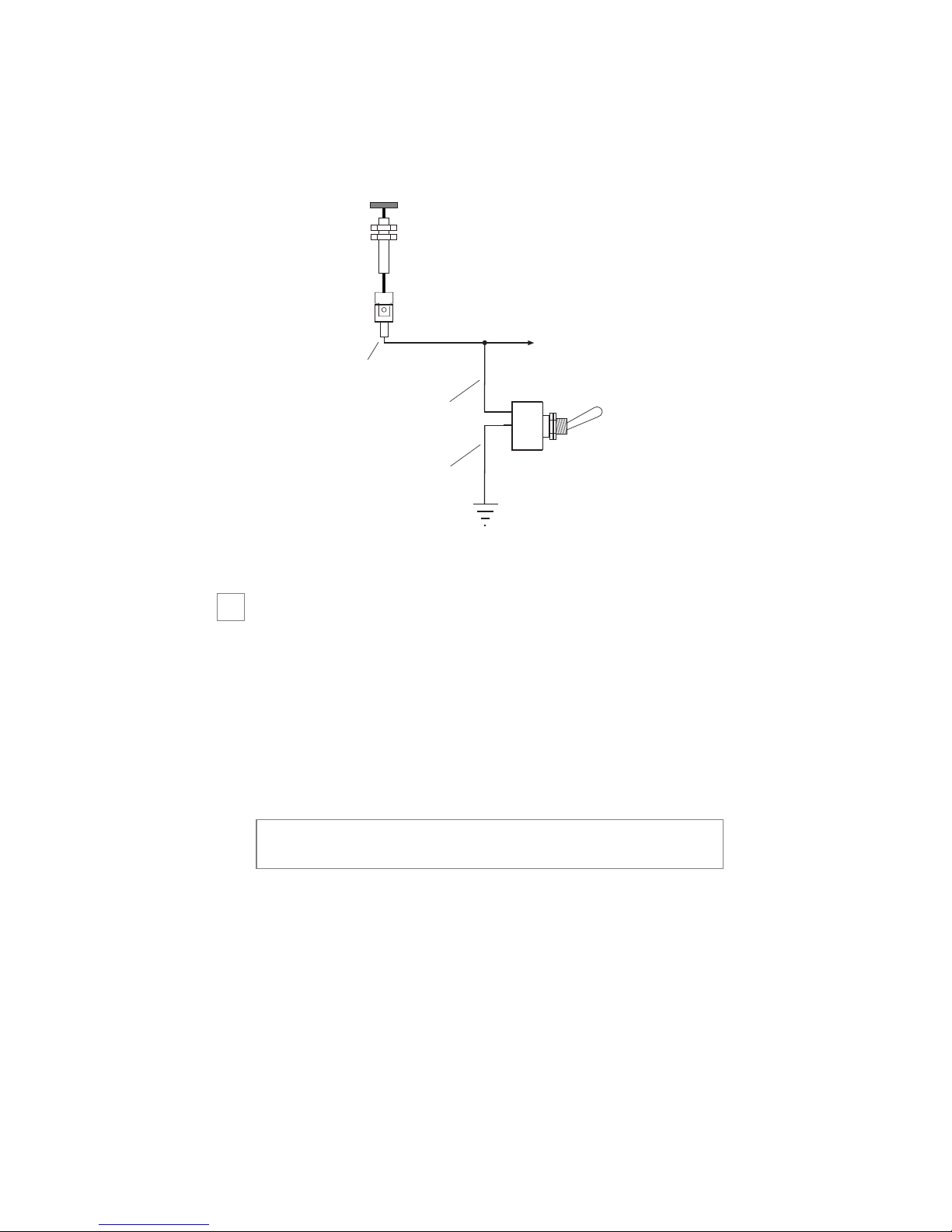
The bypass toggle switch is designed to bypass the remote start
in an emergency or to disable the remote start functions
temporarily (i.e., for service on the vehicle or when parking in an
enclosed area). This switch is to be mounted in an easily acces-
sible location in the passenger compartment.
Connect the toggle switch as shown below. The Gray (H1/5)
wire to the hood pin switch, and the Black wire from the switch
to ground. The toggle switch must be in the Off position for
normal operation.
important! Do not use the vehicle until you confirm the
operation of the hood pin shutdown.
Page 25
22
© 2005 Directed Electronics, Inc.
step 5
Parking light flash (optional)
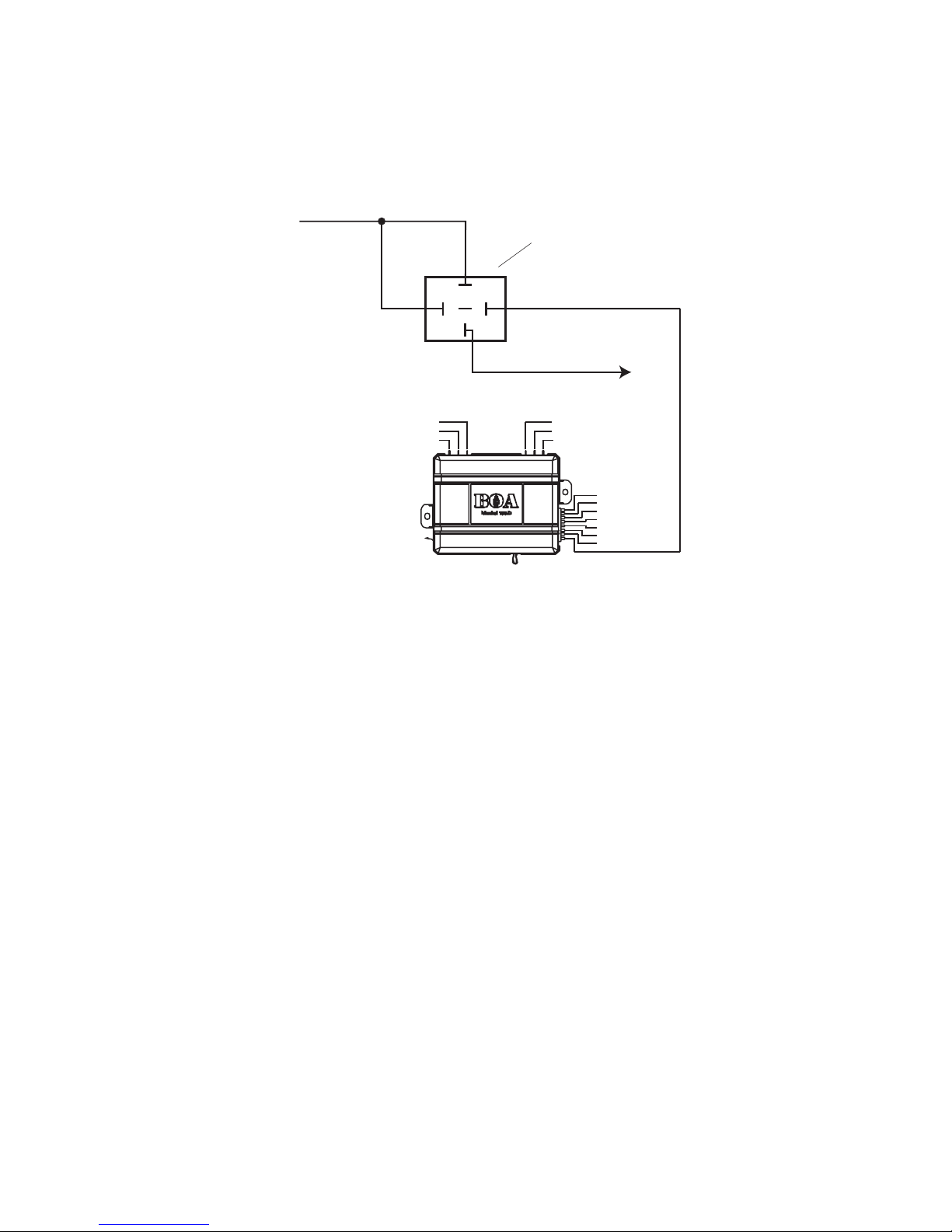
There are several different types of parking light circuits. The
following description is for a standard negative-triggered parking
light circuit, only. If the web vehicle information suggests a (+)
parking light circuit, a relay (not provided) is required. Refer to the
diagram below.
important! When parking lights are connected, they will
flash for the whole time that remote start is active.
➜
HOOD PIN SWITCH -
CONNECTOR
GRAY WIRE
BLACK WIRE
HOOD PIN SWITCH OPEN WHEN HOOD IS CLOSED
BYPASSED WHEN CLOSED
TO GRAY (H1/5) WIRE
ON
CONTROL MODULE
BYPASS
TOGGLE
SWITCH
Page 26
23
© 2005 Directed Electronics, Inc.
Using the web information on the vehicle, locate the suspected
wire and place the red lead of the LED tester to a constant (+)12
volt source and secure it. Probe the suspected wire. With the
switch in the off position the LED tester should be extinguished.
While watching the LED tester, turn the switch to the parking
light position. The LED tester should illuminate green. While
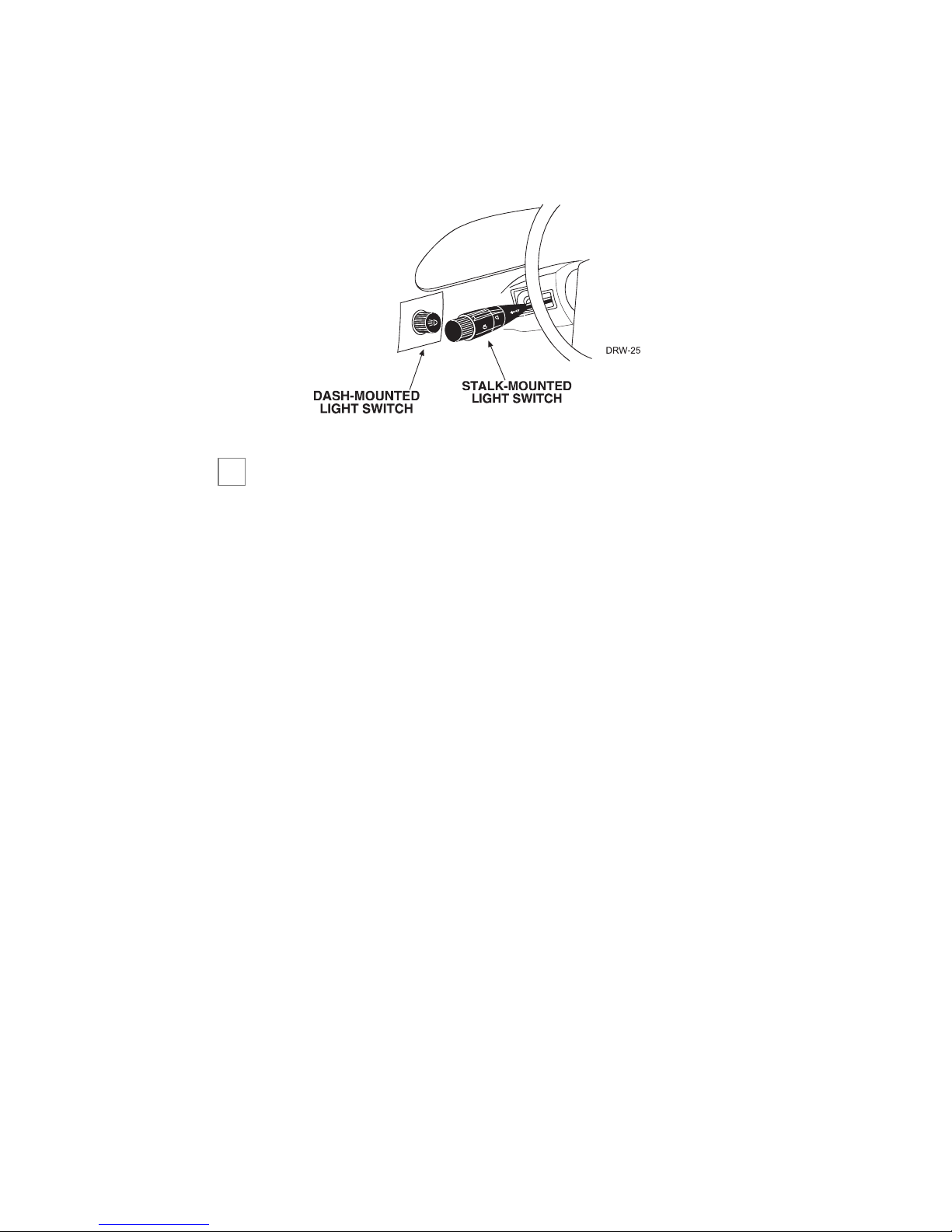
testing the suspected wire, run the dash dimmer light control up
and down — the voltage should NOT vary (LED tester illumi-
nation). If the voltage does vary, continue probing to find the
correct wire.
Once you have identified the correct wire, strip a small portion
of insulation off this wire and solder the WHITE (H1/8) wire
from the main connector to it and wrap the connection with
electrical tape.
+12 VDC CONSTANT (FUSED)
86
(+) PARKING
LIGHT RELAY
87
85
87A
30
TO POSITIVE PARKING LIGHT
WIRE IN VEHICLE
WHITE
(-) PARKING LIGHT
FLASH OUTPUT
Page 27
24
© 2005 Directed Electronics, Inc.
step 6
Engine monitoring (voltage—default setting)—optional
During remote start the system will need to know if the engine
is running. The module does this by monitoring the voltage of
the vehicle’s electrical system (or the tachometer-see next topic).
When the vehicle is not running the electrical system is approx-
imately 12 volts. The system detects the engine running when
the voltage equals or exceeds 13.5 volts. The remote start system
monitors the increase to prevent the starter from cranking when
the vehicle is already running.
If the voltage is too low, the system assumes the engine is not
running and will shut down the Ignition/Accessory circuit.
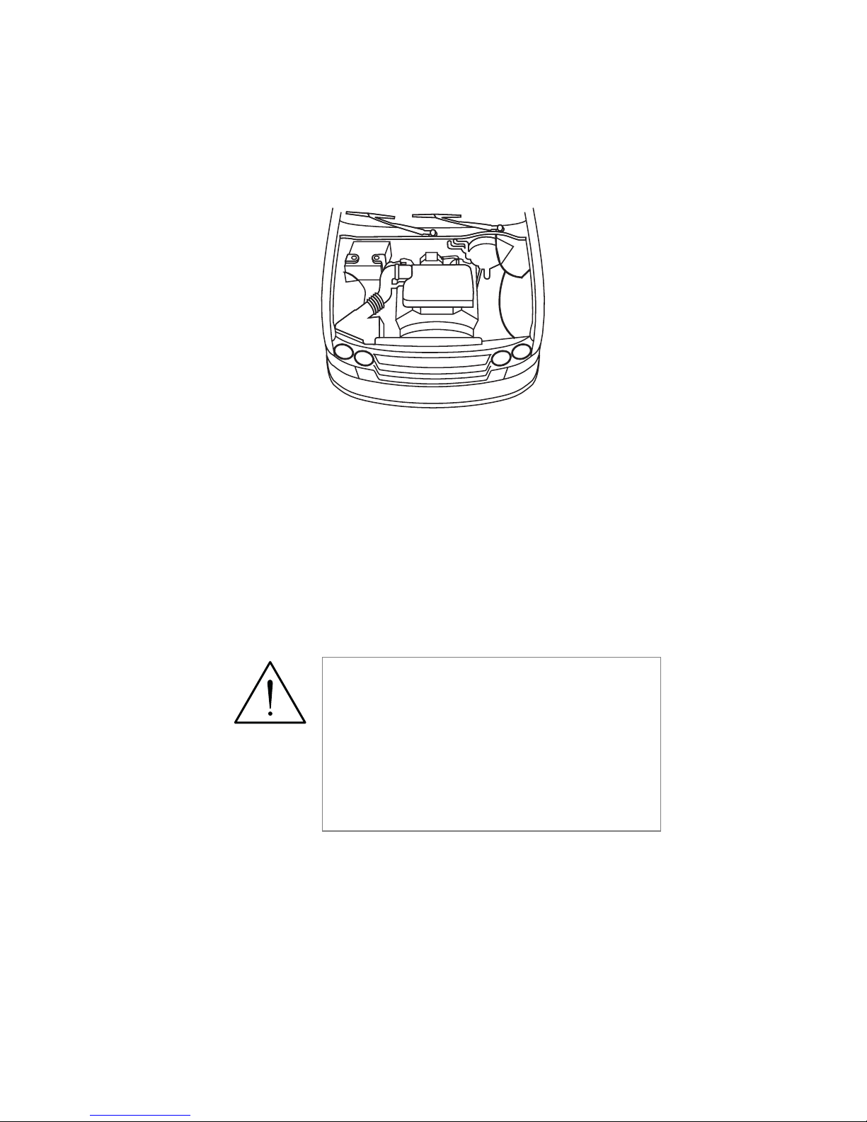
➜
Page 28
25
© 2005 Directed Electronics, Inc.
On some vehicles the electrical system has too low of a voltage
variance for the remote start module to see. In this case the
engine will not be protected from over cranking, over revolution,
or under revolution of the engine. If this is the case, it will be
necessary to use the tachometer.
Engine monitoring (tachometer—optional)
warning! In the following procedure do
not wear loose clothing that could get
entangled in rotating engine components.
Ensure that your hands and arms are well
clear of these rotating components when
working in the engine compartment.
Lastly, ensure that all wires and tools are
clear of falling into or entanglement with
these rotating components.
Page 29

26
© 2005 Directed Electronics, Inc.
Identify the suspect wire according to the web information.
Place the black lead of the multi-meter on the negative battery
post and secure it. Put the multi-meter in the AC position and
connect the probe to the suspect wire with the red lead of the
multi-meter. Then start the vehicle with the key. With the
engine at idle the multi-meter should read between .05 volts to
1.5 volts.
Have a second person press the gas pedal to increase the RPMs
and watch the meter display. When the RPMs increase the
voltage should read between 1.5 volts and 2.9 volts. Once the
correct tachometer wire has been identified, turn the vehicle off.
Run the VIOLET/WHITE (H1/2) wire from the main
connector through the firewall into the engine compartment
along side the hood pin wire. Use the same procedure as with the
hood pin wire and pull the wire through the grommet taking
extra care to keep it away from any moving parts or anything
that will generate extreme heat. Once the wire is run into the
engine compartment, strip a small portion of insulation off the
tachometer wire and solder it to the VIOLET/WHITE wire and
wrap the connection with electrical tape. Pull on the wire to
ensure a good connection.
note! In the following procedure do NOT use the LED
tester. Use of this tester can cause grounding of sensitive
electrical components causing damage, including damage
to the power train control module. Use a digital multimeter to test for this wire.
Page 30

27
© 2005 Directed Electronics, Inc.
step 7
Factory Alarm Disarm
Since some newer vehicles come equipped with a factory alarm
system, it maybe necessary for the factory alarm to be disarmed
when remote starting the vehicle. Most vehicles have a (-) disarm
trigger.
Locate the factory alarm disarm wire using the web site vehicle
information. Once the suspect wires are located, place the red
lead of the LED tester to a (+)12 volt constant source and secure
it. Probe the suspect wire with the LED tester. While probing
the wire, place the key in the drivers door cylinder. Turn it to the
unlock position and hold it when testing for the disarm wire.
The LED tester should illuminate and will extinguish when the
key is released.
When the correct wire has been found, strip a small portion of
insulation off this wire and solder the small LIGHT
GREEN/BLACK (H1/7) wire to this wire. Wrap the connection
with electrical tape.
note: Some vehicles use a + trigger system. Use the
www.boasecurity.com website to determine if your vehicle has a + trigger system. If this vehicle has this system
call
11--880000--887733--11331144
for live technical assistance as spe-
cial wiring and an additional relay is required.
➜
note! For the programming of the tachometer, refer to
the
Control Module Programming
discussion.
Page 31

28
© 2005 Directed Electronics, Inc.
step 8
Immobilizer Bypass Modules
Most newer vehicles have a factory engine immobilizer system
designed to prevent any unauthorized use of the vehicle. These
immobilizers will cut off power to the starter and the fuel supply
preventing a thief from starting the vehicle.
There are several types of immobilizers, with the most common
being the resistance based passlock/passlock 2 systems found on
most newer GM vehicles. This system can be bypassed using the
555L immobilizer bypass module available at your local retail
dealer. The majority of transponder-based immobilizer systems
can be bypassed using the 555U/556U immobilizer bypass
module available at your local retail dealer.
The BLUE wire (H1/1) of the primary harness supplies a
200mA output as soon as the control module begins the remote
start process. This wire can be used to activate an immobilizer
bypass unit.
To determine what bypass module your vehicle requires, use the
note: This unit requires you to use one of your factory keys.
You may want to acquire another key from the dealer.
note: Any vehicle equipped with a factory immobilizer
must use an immobilizer bypass module to remote start.
If not used, the vehicle ignition or fuel supply circuits
could lock up and require a costly trip to the dealer to
reset the computer system.
➜
Page 32
29
© 2005 Directed Electronics, Inc.
www.boasecurity.com
web-site in the Interface Module Look-
Up section.
step 9
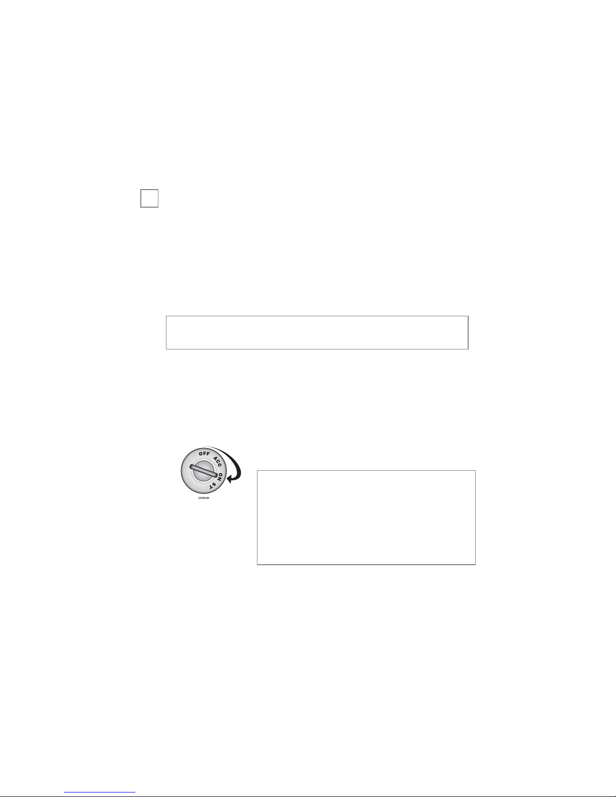
The system comes with one transmitter. The receiver can store
up to 2 different transmitter codes in memory. An additional
transmitter can be ordered by contacting your local dealer at 1-
800-274-0200. Use the following to learn the transmitter or to
add a transmitter to the system.
The following is the basic sequence of steps to remember whenever
programming this unit:
1.
FFuusseess..
Re-insert fuses into fuse holders.
2.
KKeeyy..
Turn the ignition to the ON position.
3.
PPrrooggrraamm..
After 5-seconds, press and hold the button
on the transmitter, until—(see step 4).
4.
PPaarrkkiinngg LLiigghhttss FFllaasshh..
The parking lights will flash twice to
acknowledge programming of this transmitter.
PROG
PROG
note: The system can only learn, after
being connected and with the FIRST
IGNITION ON. If not learned with
the first ignition on the main power
fuses will have to be disconnected
from the BOA unit and then reconnected and the procedure repeated.
note: If power is lost to the control module (battery disconnected), the transmitters must be relearned.
➜
Page 33

30
© 2005 Directed Electronics, Inc.
To add a second transmitter (within 5-seconds of the first trans-
mitter parking light flash learn acknowledgment):
1.
PPrrooggrraamm..
Hold the button on the additional trans-
mitter for an additional 5-seconds, until—(see step 2).
2.
PPaarrkkiinngg LLiigghhttss FFllaasshh..
The parking lights will flash twice to
acknowledge programming of this transmitter.
step 10
Testing the system
Once steps 1-9 have been completed, the operation of the
system can be tested.
Make sure that the vehicle is in park with the emergency brake
on and the hood closed. Press twice on the remote
control to initiate the remote start function (this may take a
moment to initiate). The parking lights should flash to confirm
the remote start command has been received, The accessories
and ignition should turn on followed by the starter cranking and
the vehicle engine running. Pressing on the remote will
shut the engine off.
START
START
PROG
PROG
ARM
ARM
STOP
STOP
START
START
PROG
PROG
ARM
ARM
➜
PROG
PROG
important: When programming a remote ensure to hold the
remote about 4-feet away from the BOA unit. If the remote
is too close to the unit, the remote may not program.
note: A second transmitter can only be added to the system immediately after programming the first transmitter.
Page 34
31
© 2005 Directed Electronics, Inc.
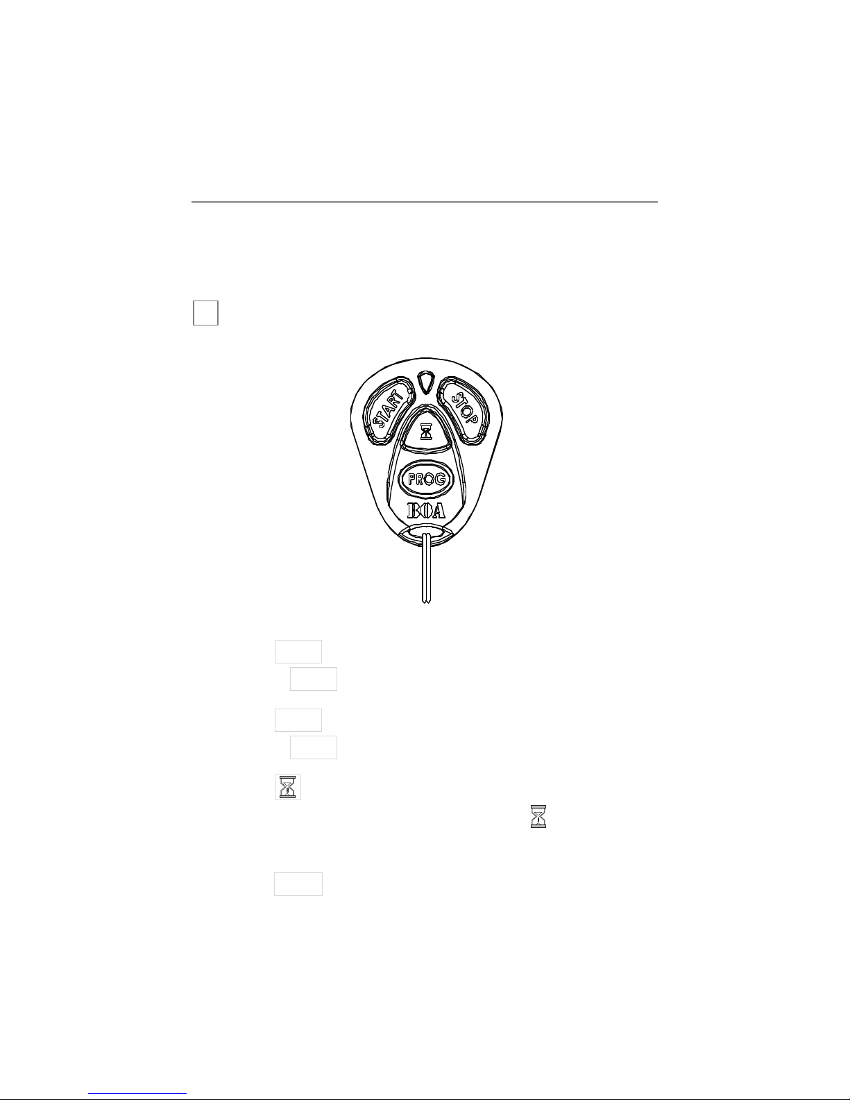
ttrraannssmmiitttteerr ffuunnccttiioonnss
The receiver uses a computer-based learn routine to learn the
transmitter buttons.
standard configuration
Button
Press the button twice to remote start the vehicle.
Button
Press the button once to remote stop the vehicle.
Button
This button engages timer mode. Press the button to start
the engine every 3 hours (12-minute run time).
Button
This button is used to program the system.
PROG
PROG
START
START
PROG
PROG
ARM
ARM
STOP
STOP
START
START
PROG
PROG
ARM
ARM
STOP
STOP
START
PROG
PROG
ARM
ARM
START
PROG
PROG
ARM
ARM
➜
Page 35

32
© 2005 Directed Electronics, Inc.
CCoonnttrrooll MMoodduullee PPrrooggrraammmmiinngg
Depending on the vehicle, use the following data with the
instructions to program your system. These wire loops are found
at the side of the control module.
DDiieesseell MMooddee ((BBLLUUEE))
- Cut this loop if you have a diesel vehicle.
When cut the remote start will start the engine about 30 seconds
after pressing the button twice.
Uncut – Gas Mode
Cut – Diesel Mode
VVoollttaaggee MMooddee//TTaacchhoommeetteerr MMooddee
- Default is voltage mode. The
control module will automatically look at the tachometer input
during normal driving. If it finds a valid tachometer signal the
module will use tachometer mode, otherwise the module will use
voltage mode (battery voltage will rise after the engine starts).
To program tachometer mode, start the engine and let it run for
at least 30 seconds. If the tachometer is seen by the control
module, it will enter tachometer mode, and will monitor the
tachometer input for the next startup.
The system is programmed to attempt two starts using
tachometer mode. If after the second start attempt the control
module did not see a tachometer input the system will attempt
to start a third time using voltage mode.
START
START
PROG
PROG
ARM
ARM
Page 36

33
© 2005 Directed Electronics, Inc.
uussiinngg yyoouurr ssyysstteemm
warning! safety first
The following safety warnings must be observed at all times:
■ When properly installed, this system can start the vehicle
via a command signal from the remote control transmitter.
Therefore, never operate the system in an enclosed area or
partially enclosed area without ventilation (such as a garage).
When parking in an enclosed or partially enclosed area or when
having the vehicle serviced, the remote start system must be
disabled using the installed toggle switch. It is the user's sole
responsibility to properly handle and keep out of reach from
children all remote control transmitters to assure that the system
does not unintentionally remote start the vehicle.
TTHHEE UUSSEERR
MMUUSSTT IINNSSTTAALLLL AA CCAARRBBOONN MMOONNOOXXIIDDEE DDEETTEECCTTOORR
IINN OORR AABBOOUUTT TTHHEE LLIIVVIINNGG AARREEAA AADDJJAACCEENNTT TTOO TTHHEE
VVEEH
HIICCLLEE.. AALLLL DDOOOORRSS LLEEAADDIINNGG FFRROOMM AADDJJAACCEENNTT
LLIIVVIINNGG AARREEAASS TTOO TTHHEE EENNCCLLOOSSEEDD OORR PPAARRTTIIAALLLLYY
EENNCCLLOOSSEEDD VVEEHHIICCLLEE SSTTO
ORRAAGGEE AARREEAA MMUUSSTT AATT AALLLL
TTIIMMEESS RREEMMAAIINN CCLLOOSSEEDD..
These precautions are the sole
responsibility of the user.
■ Use of this product in a manner contrary to its intended
mode of operation may result in property damage, personal
injury, or death. (1) Never remotely start the vehicle with the
vehicle in gear, and (2) Never remotely start the vehicle with the
keys in the ignition. The user must also have the neutral safety
➜
Page 37

34
© 2005 Directed Electronics, Inc.
feature of the vehicle periodically checked, wherein the vehicle
must not remotely start while the car is in gear. This testing
should be performed by an authorized Directed Electronics, Inc.
dealer in accordance with the Safety Check outlined in the
product installation guide. If the vehicle starts in gear, cease
remote start operation immediately and consult with the autho-
rized Directed Electronics, Inc.dealer to fix the problem.
■ After the remote start module has been installed, contact
your authorized dealer to have him or her test the remote start
module by performing the Safety Check outlined in the product
installation guide. If the vehicle starts when performing the
Neutral Safety Shutdown Circuit test, the remote start unit has
not been properly installed. The remote start module must be
removed or the installer must properly reinstall the remote start
system so that the vehicle does not start in gear. All installations
must be performed by an authorized Directed Electronics dealer.
OOPPEERRAATTIIOONN OOFF TTHHEE RREEMMOOTTEE SSTTAARRTT MMOODDUULLEE IIFF
TTHHEE VVEEHHIICCLLEE SSTTAARRTTSS IINN GGEEAARR IISS CCOONNTTRRAARRYY TTOO IITTSS
IINNTTEENNDDEEDD
MMOODDEE OOFF OOPPEERRAATTIIOONN.. OOPPEERRAATTIINNGG TTHHEE
RREEMMOOTTEE SSTTAARRTT SSYYSSTTEEMM UUNNDDEERR TTHHEESSEE CCOONNDDII--
TTIIOONNSS MMAAYY RREESSUULLTT IINN PPRROOPPEERRTTY
Y DDAAMMAAGGEE OORR
PPEERRSSOONNAALL IINNJJUURRYY.. YYOOUU MMUUSSTT IIMMMMEEDDIIAATTEELLYY CCEEAASSEE
TTHHEE UUSSEE OOFF TTHHEE UUNNIITT AANNDD SSEEEEKK TTHHEE AASSSSIISSTTAANNCCEE
OO
FF AANN AAUUTTHHOORRIIZZEEDD DDIIRREECCTTEEDD EELLEECCTTRROONNIICCSS,, IINNCC..
DDEEAALLEERR TTOO RREEPPAAIIRR OORR DDIISSCCOONNNNEECCTT TTHHEE
IINNSSTTAALLLLEEDD RREEMMOOTTEE SSTTAARRTT
MMOODDUULLEE.. DDIIRREECCTTEEDD
EELLEECCTTRROONNIICCSS,, IINNCC..WWIILLLL NNOOTT BBEE HHEELLDD RREESSPPOONN--
SSIIBBLLEE OORR PPAAYY FFOORR IINNSSTTAALLLLAATTIIOONN OORR RREEIINNSSTTAAL
LLLAA--
TTIIOONN CCOOSSTTSS..
Page 38
35
© 2005 Directed Electronics, Inc.
remote start
This feature allows you to remotely start your vehicle. This
makes it possible to warm up the engine, as well as adjust the
interior temperature of the vehicle with the climate control
system. If interior heating or cooling is desired, the climate
controls must be preset, and the fan blower must be set to the
desired level prior to remote starting the vehicle.
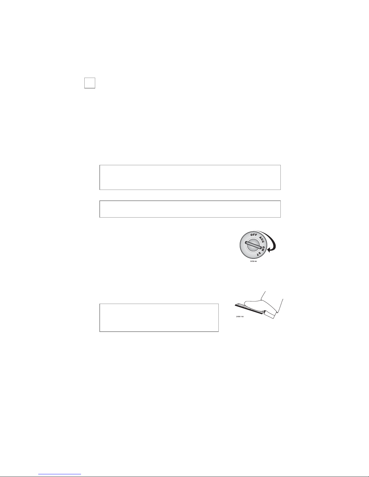
WWhheenn yyoouu aarree rreeaaddyy ttoo ddrriivvee tthhee vveehhiiccllee::
1. Insert the ignition key and turn it to the
ON (not the START) position.
2. Press the brake pedal.
While the vehicle is running during remote start operation, the
system will monitor the vehicle and will automatically shut
down the engine if the system receives any of the following shut-
down inputs:
nnoottee::
If the brake pedal is pressed
before the key is in the ON position, the engine will shut down.
nnoottee::
When remote starting is activated the vehicle’s park-
ing lights will flash.
nnoottee::
(1) Never remotely start the vehicle with the vehicle in gear, and (2) Never remotely start the vehicle with the
key in the ignition.
➜
Page 39
36
© 2005 Directed Electronics, Inc.
■ The brake pedal is pressed.
■ The hood is opened.
■ The shutdown toggle switch is put into the ON position.
■ The pre-programmed run time has elapsed (12-minutes).
■ The button is pressed.
■ The tachometer is either too high or low.
■ The battery voltage is too low.
timer mode
This feature allows you to remotely start and run your vehicle for
12-minutes every 3 hours (for a maximum of 6 starts for cold
weather conditions). This makes it possible to warm up the
engine, as well as adjust the interior temperature of the vehicle
with the climate control system. If interior heating or cooling is
desired, the climate controls must be preset, and the fan blower
must be set to the desired level prior to remote starting the vehicle.
To remote start the vehicle in timer mode:
1. Press the button on the transmitter twice within 3
seconds.
ARM
ARM
nnoottee::
(1) Never remotely start the vehicle with the vehicle in gear, and (2) Never remotely start the vehicle with the
key in the ignition.
➜
START
START
PROG
PROG
ARM
ARM
STOP
STOP
Page 40

37
© 2005 Directed Electronics, Inc.
2. The parking lights will flash 4 times to confirm remote start
timer operation.
3. The vehicle will start every 3 hours, it will run for a period
of 12-minutes or until a shutdown input is triggered.
Remote start timer mode is cancelled by:
■ Activation of the ignition (turning the ignition key On)
■ The car has started 6 times.
■ The brake pedal is pressed.
■ The hood is opened.
■ The shutdown toggle switch is put into the ON position.
■ Note: The button on the transmitter can be
pressed at any time to stop the engine during the 12-minute
timer engine run interval. The button does not affect
the 3-hour time interval between engine starts. If the engine
fails to start on 3 attempts it is counted as one start in time
mode. The system will attempt to start again 3-hours later (if
this wasn’t its 6thstart attempt).
START
START
PROG
PROG
ARM
ARM
STOP
STOP
START
START
PROG
PROG
ARM
ARM
STOP
STOP
Page 41

38
© 2005 Directed Electronics, Inc.
ppiitt ssttoopp mmooddee
This feature allows you to exit the car and leave the engine
running. Use the following procedure to enter Pit Stop Mode:
1. Place the transmission in park and put the parking brake on.
2. Leave the ignition on.
3. Do not step on the brake.
4. Press the button twice. The parking lights will flash
twice to confirm pit stop mode.
5. Turn the key off and remove the key.
6. Exit and lock the vehicle.
Use the following procedure to exit Pit Stop Mode:
1. Enter the vehicle.
2. Place the key into the on (not the crank or start) position.
3. Step on the brake (this causes the system to exit Pit Stop Mode).
ccooddee hhooppppiinngg ®®rree--ssyynncchhrroonniizzee
If the transmitter is pressed many times out of range, or the
battery is removed, the transmitter may get temporarily out of
sync and fail to operate the system. To synchronize the trans-
START
PROG
PROG
ARM
ARM
Page 42

39
© 2005 Directed Electronics, Inc.
mitter, simply press or several times within range
of the vehicle. The system will automatically synchronize and the
transmitter will respond normally.
ttrroouubblleesshhoooottiinngg
➤
TThhee iiggnniittiioonn ccoommeess oonn,, bbuutt tthhee ssttaarrtteerr wwiillll nnoott ccrraannkk..
Does it start with the key in the ignition? If so, does the
vehicle have an engine immobilizer?
Will it start with the brake pedal depressed? (Make sure to
disconnect the brake shutdown when performing this test.)
If so, it may have a brake/starter interlock.
Is the correct starter wire being energized? Check by ener-
gizing it yourself with a fused test lead.
➤
TThhee ssttaarrtteerr ccrraannkkss ffoorr 11 oorr 22--sseeccoonnddss bbuutt ddooeess nnoott ssttaarrtt..
Either the wrong ignition wire is being energized, the system’s
ignition and accessory wires have been connected backwards,
or the vehicle has two ignition circuits. Try activating the unit
with the ignition key in the “run” position. If the vehicle then
runs normally, retest your ignition system.
START
PROG
PROG
ARM
ARM
STOP
STOP
START
PROG
PROG
ARM
ARM
Page 43

40
© 2005 Directed Electronics, Inc.
➤
TThhee ssttaarrtteerr ccoonnttiinnuueess ttoo ccrraannkk eevveenn tthhoouugghh tthhee eennggiinnee hhaass
ssttaarrtteedd..
Has the tach wire been learned? See the Tach Learning
section of this guide.
Is the tach wire receiving the correct information? Either the
wrong tach wire has been used, or a bad connection exists.
➤
TThhee cclliimmaattee ccoonnttrrooll ssyysstteemm ddooeess nnoott wwoorrkk wwhhiillee tthhee uunniitt iiss
ooppeerraattiinngg tthhee vveehhiiccllee..
Either the wrong accessory wire is being energized or more
than one ignition or accessory wire must be energized in
order to operate the climate control system.
➤
TThhee rreemmoottee ssttaarrtt wwiillll nnoott aaccttiivvaattee..
Check harnesses and connections. Make sure the harnesses
are fully plugged into the remote start module. Make sure
there are good connections to the vehicle wiring.
Check voltage and fuses. Use a meter and check for voltage
between the RED wire and the BLACK ground wire. If you
have less than battery voltage, check both 30A fuses on the
main power wires. Also make sure that the ground wire is
going to a good paint-free chassis ground.
➤
TThhee rreemmoottee ssttaarrtt wwiillll aaccttiivvaattee bbuutt tthhee ssttaarrtteerr nneevveerr eennggaaggeess..
1. Check for voltage on the purple starter wire two seconds
after the remote start becomes active. If there is voltage
present, skip to Step 4. If there is no voltage present, advance
to Step 2.
Page 44

41
© 2005 Directed Electronics, Inc.
2. Check the 30A fuses.
3. Does the vehicle have an immobilizer? Some immobilizer
systems will not allow the vehicle to crank if active.
4. Check connections. The two red heavy gauge input wires
should have solid connections. "T-taps", or "scotch locks"
are not recommended for any high current heavy gauge
wiring. Also, if the vehicle has more than one 12-volt input
wire, then connect one red wire to each.
➤
TThhee vveehhiiccllee ssttaarrttss,, bbuutt iimmmmeeddiiaatteellyy ddiieess..
Does the vehicle have an immobilizer? The vehicle’s immo-
bilizer will cut the fuel and/or spark during unauthorized
starting attempts.
➤
TThhee vveehhiiccllee wwiillll ssttaarrtt aanndd rruunn oonnllyy ffoorr aabboouutt 1100 sseeccoonnddss..
Is the remote start programmed for voltage sense? Try
programming the unit using a tach wire.
gglloossssaarryy ooff tteerrmmss
Control Module:
The “brain” of your system. Usually hidden
under the dash area of the vehicle. It houses the microprocessor
that monitors your vehicle and controls all system functions.
Transmitter:
A hand-held, remote control which operates the
various functions of your system.
Page 45

42
© 2005 Directed Electronics, Inc.
nnootteess
_________________________________________________
_________________________________________________
_________________________________________________
_________________________________________________
_________________________________________________
_________________________________________________
_________________________________________________
_________________________________________________
_________________________________________________
_________________________________________________
_________________________________________________
_________________________________________________
_________________________________________________
_________________________________________________
_________________________________________________
_________________________________________________
_________________________________________________
_________________________________________________
_________________________________________________
_________________________________________________
_________________________________________________
Page 46

CCuutt aalloonngg ddootttteedd lliinnee aanndd ffoolldd ffoorr aa qquuiicckk aanndd eeaassyy rreeffeerreennccee ttoo kkeeeepp iinn yyoouurr ppuurrssee oorr wwaalllleett..
✂
✂
QQUUIICCKK RREEFFEERREENNCCEE GGUUIIDDEE::
TToo rreemmoottee ssttaarrtt uussiinngg yyoouurr rreemmoottee
■ Press twice within three seconds. The parking lights will flash
once to confirm.
TToo rreemmoottee ssttoopp uussiinngg yyoouurr rreemmoottee
■ Press once. The parking lights will flash once to confirm.
TToo uussee ttiimmeerr mmooddee
■ Press the button twice within 3 seconds. The parking lights will
flash four times to confirm timer mode operation.
TToo uussee PPiitt SSttoopp mmooddee
■ Parking brake on, transmission in Park.
■ Ignition On (don’t hit brake pedal), activate remote start.
■ Remove ignition key, exit and manually lock vehicle.
■ To Exit pit stop mode, enter vehicle.
■ Place the ignition key to the on (not start or crank) position.
■ Depress brake pedal, to disengage Pit Stop mode—the vehicle will con-
tinue running.
ARM
ARM
PROG
PROG
ARM
ARM
STOP
STOP
START
PROG
PROG
ARM
ARM
QQUUIICCKK RREEFFEERREENNCCEE GGUUIIDDEE::
TToo rreemmoottee ssttaarrtt uussiinngg yyoouurr rreemmoottee
■ Press twice within three seconds. The parking lights will flash
once to confirm.
TToo rreemmoottee ssttoopp uussiinngg yyoouurr rreemmoottee
■ Press once. The parking lights will flash once to confirm.
TToo uussee ttiimmeerr mmooddee
■ Press the button twice within 3 seconds. The parking lights will
flash four times to confirm timer mode operation.
TToo uussee PPiitt SSttoopp mmooddee
■ Parking brake on, transmission in Park.
■ Ignition On (don’t hit brake pedal), activate remote start.
■ Remove ignition key, exit and manually lock vehicle.
■ To Exit pit stop mode, enter vehicle.
■ Place the ignition key to the on (not start or crank) position.
■ Depress brake pedal, to disengage Pit Stop mode—the vehicle will con-
tinue running.
ARM
ARM
PROG
PROG
ARM
ARM
STOP
STOP
START
PROG
PROG
ARM
ARM
Page 47

The company behind this system is Directed Electronics, Inc.
Since its inception, Directed Electronics has had one purpose, to provide consumers with
the finest vehicle security and car stereo products and accessories available. The recipient of
nearly 100 patents and Innovations Awards in the field of advanced electronic
technology, DIRECTED is ISO 9001 registered.
Quality Directed Electronics products are sold and serviced throughout North America
and around the world.
Call
((880000)) 227744--00220000
for more information about our products and services.
Directed Electronics, Inc.
Vista, CA 92081
www.directed.com
© 2005 Directed Electronics, Inc. - All rights reserved
G165B 03-05
Directed Electronics is committed to delivering world class quality products
and services that excite and delight our customers.
 Loading...