

Page 1
BNTMM01
INSTRUCTIONS FOR:-
HEATING MATS
M SERIES
IMPORTANT:
PLEASE READ THESE INSTRUCTIONS, NOTE THE SAFE OPERATIONAL
REQUIREMENTS, WARNINGS, AND CAUTIONS. USE THIS PRODUCT CORRECTLY, AND WITH
CARE FOR THE PURPOSE FOR WHICH IT IS INTENDED. FAILURE TO DO SO MAY CAUSE
DAMAGE AND/OR PERSONAL INJURY AND WILL INVALIDATE THE WARRANTY.
Thank you for purchasing a BN Thermic product. Manufactured to a high standard this product will, if used according
to these instructions and properly maintained, give you years of trouble free performance.
INSTALLATION AND OPERATING INSTRUCTIONS
Retain these instructions for future reference.
1. Personnel.
The M Series Mats should be installed by a suitably qualified, professional builder and/or electrician. M Series
Mats are not a ‘do it yourself’ product. It is most important that the installer completes the Installation Record
Form that is part of this booklet.
2. Check the suitability of sub-floor.
These mats can be installed onto concrete or wooden sub-floors. We do not recommend installation onto
asphalt sub-floors or any insulation material other than rigid boards.
3. Check the suitability of the tile adhesive.
M Series is designed to sit in a layer of adhesive below ceramic or stone tiles. M Series has been used with a
wide variety of tile adhesives. We suggest that the suitability of any given adhesive be confirmed by the
adhesive supplier.
If preferred M Series can be buried in a layer of screed. If you intend to use a compound other than a cement
screed, the suitability of the compound should be confirmed by the compound supplier.
4. Check the suitability of the floor surface.
M Series is generally used with ceramic and stone floors, including slate and marble. When used with other
floor surfaces such as vinyl or carpet you should always confirm suitability with your flooring supplier.
5. Check that you have the correct M Series mat
Firstly you must calculate the area of floor to be heated. This will be the total floor area minus the area
occupied by fixtures such as cupboards, sinks, baths etc. Refer to the schedule of mats to find the mat with a
square area slightly lower than you calculated figure. This is likely to be the mat for you.
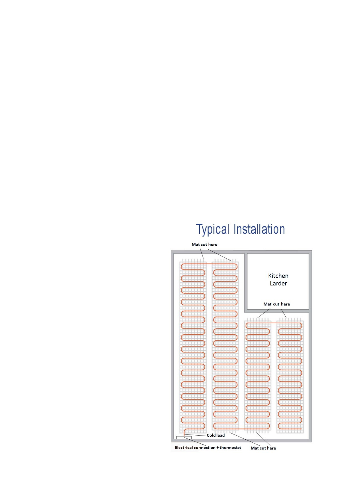
To double-check your selection, draw a sketch of the free area. Leaving a space of 30mm between mat runs
and 80mm between the mats and the wall, draw the mat runs onto your sketch. Remember you can cut the
mat at any point along its length but you cannot alter its width.
If you are unsure whether there is quite enough space to install a particular M Series mat, you should consider
using a slightly smaller mat. REMEMBER ALTHOUGH YOU CAN CUT THE MAT AT ANY POINT YOU MUST
NOT CUT THE HEATING CABLE.
6. Check the suitability of the controller
Ensure that the total installed load does not exceed the switching capacity of the selected controller. Larger
loads can be switched using a suitably rated contactor.
NEVER APPLY POWER (Voltage) TO THE MAT WHILE IT IS ROLLED UP
Page 2
7. Check
Before starting installation and before unrolling the mat, the resistance of the cable should
be measured and recorded on the Installation Record Form. Ensure that the reading taken is consistent with
the nominal output of the cable.
An insulation resistance reading should also be taken between either end of the cold lead conductor and the
earth braid using a 500V dc Insulation Resistance Meter (Megger). Readings in excess of 20 meg-ohms are
acceptable. Again the reading should be recorded on the Installation Record Form.
8. Check and preparing the sub-floor
Ensure that the surface of the sub-floor is clean and free from any debris or sharp objects and suitable primer
should then be applied.
9. Cutting a groove for PVC pipes
Both the controller probe and cold lead should be run through a plastic pipe of an appropriate diameter
(typically 10mm diameter plastic hose). This is particularly important where the probe or cold lead pass from
the floor to the wall. To keep the floor level as low as possible, grooves can be cut into the sub-floor to
accommodate these pipes.
10. Positioning the controller probe
The controller probe should be mounted in a plastic pipe. The end of the probe should be a minimum of
500mm from the wall and 30mm from a heating cable. Remember to seal the end of the plastic tube with tape
to prevent ingress of the adhesive.
11. Laying the M Series mat
An M Series mat has four strips of tape running
along its length. The two outside strips are double
sided and these should be used to fix the mat to
the primed sub-floor with the cable side up.
At this stage it is good practice to take a
photograph of the floor. This will be a useful
record should you need to carry out any work on
the floor (for example drilling holes).
The tile adhesive can then be applied in the
normal way taking care to ensure that the heating
cable is completely covered and surrounded by
the adhesive. Before applying the tiles and before
the adhesive dries, carry out the second electrical
check (see below).
It is essential to avoid mechanical damage to the
heating cable. If it is impossible to avoid walking
on the cable, use soft-shoes and/or crawling
boards.
When you have finished laying the mat, you
simply stop. There is no requirement to return the
end of the cable to the connection point. The
hot/cold junction must be in the floor itself and not
in free air. It is most important that the cables are
not allowed to touch each other or cross.
Page 3

BN Thermic Ltd,
34 Stephenson Way, Three
Bridges,
Crawley, RH10 1TN
Tel: +44 (0) 1293 547361
Email: [email protected]
This product conforms to EU Directive 2002/96/EC.
This appliance bears the symbol of the crossed waste bin. This indicates that, at the end of its useful life, it must not be disposed of as
domestic waste, but must be taken to a collection centre for waste electrical and electronic equipment. It is the user's responsibility to
dispose of this appliance through the appropriate channels. Failure to do so may incur penalties established by laws governing
waste disposal.
12. Second electrical check
Once the mat has been laid onto the sub-floor and before the adhesive dries, the following checks should be
performed. All results should be recorded on the Installation Record Form.
Ensure that the resistance reading (ohms) is as recorded after the first electrical check Measure the insulation
resistance between either end of the cold lead conductor and the earth braid using a 500V dc Insulation
Resistance Meter (Megger), ensure that the insulation resistance is still in excess of 20 meg-ohms.
13. Apply the tiles
14. Third electrical check
Once the tiles have been applied, the following checks should be performed. All results should be recorded on
the Installation Record Form.
Ensure that the resistance reading (ohms) is as recorded after the first electrical check Measure the insulation
resistance between either end of the cold lead conductor and the earth braid using a 500V dc Insulation
Resistance Meter (Megger), ensure that the insulation resistance is still in excess of 20 meg-ohms.
15. Electrical connection
Follow the electrical connection instructions supplied with the controller.
16. Energising
The system should NOT be energised within until the floor is completely dry. This can take up to 28 days. To do
so may damage the heating cable.
NOTE:
It is our policy to continually improve products and as such we reserve the right to alter data, specifications and component parts without prior
notice.
IMPORTANT:
WARRANTY:
This guarantee is validated by the Installation Record form which is supplied with every
underfloor heating product being fully completed by the qualified installing contractor at the time
of installation and returned to BN Thermic Ltd within 60 days of installation. This guarantee
covers the full purchase price of the product only. Control devices carry the manufacturers 1 year
warranty.
an addition to consumer liability rights.
No liability is accepted for incorrect use of this product.
Your BN Thermic product is guaranteed for ten years from date of purchase.
This guarantee in no way prejudices your rights under common law and is offered as
MINS-v01
Page 4

M SERIES HEATER MAT INSTALLATION RECORD FORM
Please complete this form at the time of installation and post to BN Thermic within 60 days of installation. We strongly advise you to
retain a copy for your records. Warranty claims will not be considered if the form has not been completed and returned to us within
the required time.
Name of property owner
Address
Telephone number
Purchased from:
(Name and location of Wholesaler)
Date of purchase
Name of company who installed the system
Installer’s telephone number
Date of installation
Date the system was energised
M Series Model Number
Model number of controller
Room (bathroom, kitchen etc)
Dimensions of room, excluding permanent fixtures
such as cupboards and baths. (if the room is of a
complex shape you may prefer to make a
dimensioned sketch and attach it to this form)
Surface on to which the heating cable or mat was laid
Type of bedding compound or adhesive used
Thickness of bedding compound or adhesive
Type of floor surface
Thickness of floor surface
Electrical Checks – Refer to the Installation Instructions
First electrical check
Resistance (ohms)
Insulation resistance (meg-ohms)
Second electrical check
Resistance (ohms)
Insulation resistance (meg-ohms)
Third electrical check
Resistance (ohms)
Insulation resistance (meg-ohms)
Assuming correct installation, BN Thermic underfloor heating systems will give many years of satisfactory
service. In the un- likely event of a malfunction resulting from faulty manufacture, the systems are guaranteed
for a period of 10 years from date of purchase. The guarantee covers the full purchase price but not the cost of
repairing or replacing the heater in the floor. Control devices carry the manufacturers 1 year warranty only.
BN Thermic Ltd,
34 Stephenson Way, Three Bridges, Crawley, RH10 1TN
 Loading...