

Page 1
Rev 11/2/2020
1
SIGMA
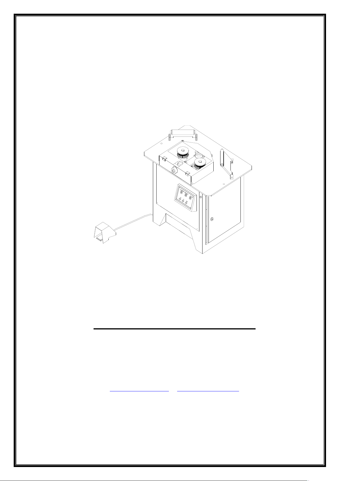
MECHANICAL SPIRAL MACHINE FOR REBAR
DSX 25
Operating & Maintenance Manual
SALES & SERVICE BY
BN PRODUCTS – USA, LLC
3450 SABIN BROWN ROAD
WICKENBURG,AZ 85390
(928) 992-3833
Page 2
Rev 11/2/2020
2
Overview
The DSX 25 Spiral Bending Machine is designed and manufactured for spiral bending of round
and rigid metallic bar materials. All other purposes of use are not supported. This machine can
be operated for various shapes of bending. In order to get the best results from your DSX 25,
locate it in such a position so as to be operated easily, and to provide ample space around the
machine.
We recommend you to locate workbenches in both sides of the machine. The length of each
bench should equal the longest length of the rebar material to be bent.
Important Warning
• Prior to operate the machine read through this Operating & Maintenance Manual, carefully.
• Only the qualified personnel are allowed to operate the machine.
• Disconnect the power prior to make checks, maintenance, lubrication, and/or adjustments.
• Observe all guidelines provided in this Operating & Maintenance Manual.
1. SET-UP PROCEDURES
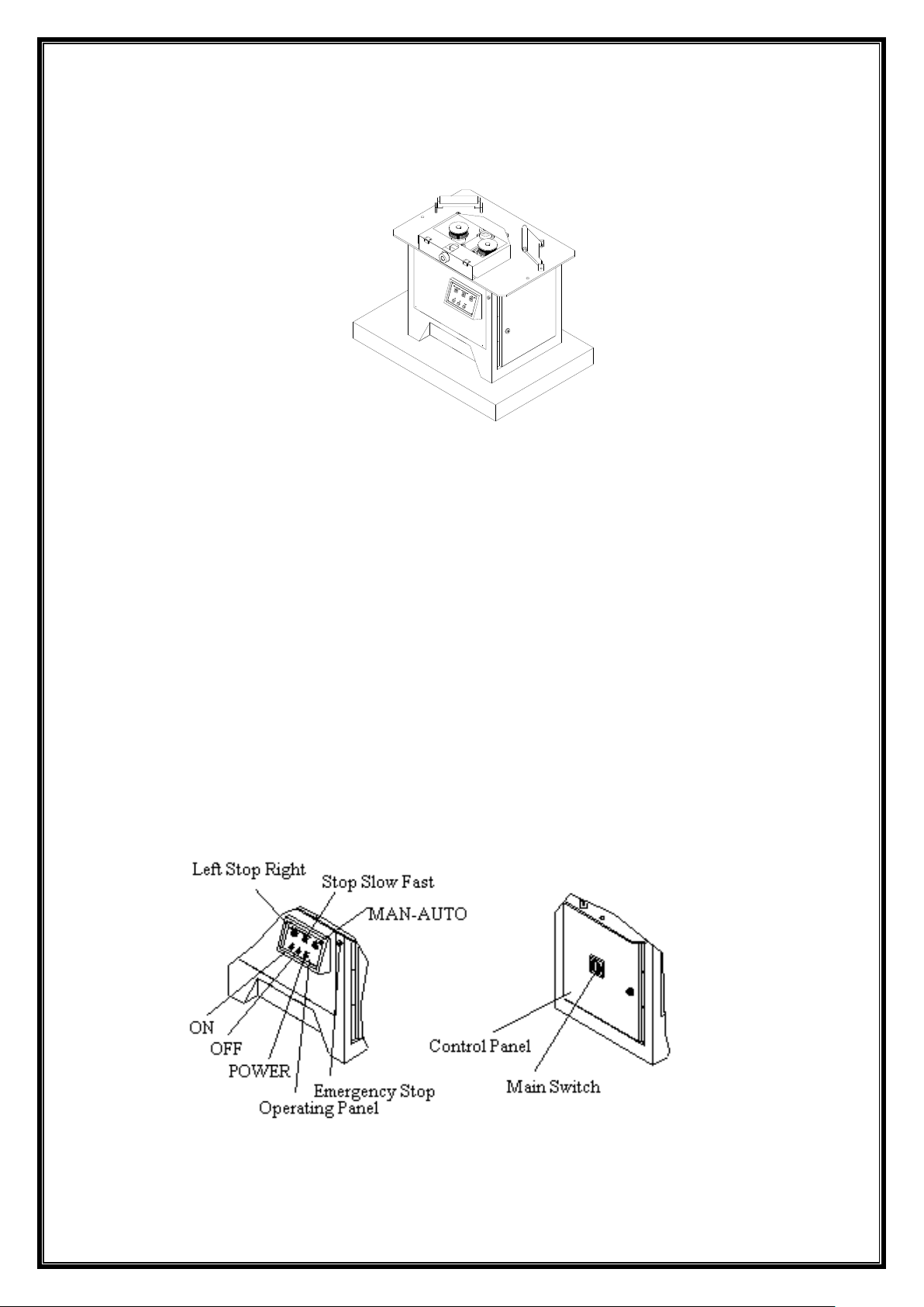
1.1 Level the machine on a flat and supported floor surface / ground (Figure 1).
1.2 Made the power connection by a qualified electrician.
Note: Power Connection
1.3 Plug on the power supply cord of 5x4 mm2 to the feeding line of main power.
1.4 Grounding is required. Do not operate the machine without grounded power.
Grounding Connection: Follow the procedure below. Connect one end of the ground cable to
a copper wire (minimum16 mm) so as to ensure electrical conductivity. The other end of the
Page 3
Rev 11/2/2020
3
cable is to be connected to a tube having ability of conductivity dipped sufficiently into the
ground (into the damp soil, preferably), or to a copper plate buried under the soil as deeper as
possible.
FIGURE 1
1.2. START UP PROCEDURE
1.2.1 Check and ensure that the machine is installed in accordance with instructions.
1.2.2 Remove all parts (including bending apparatus) from the top surface of the machine.
1.2.3 Turn the switch (LEFT/STOP/RIGHT) to the LEFT or RIGHT, and the switch (MANAUTO) to the MAN position, and determine the direction of rotation of the machine by pressing
the food pedal down.
Note: The clockwise rotation is accepted as the right rotation and the counter clockwise
rotation as the left from the front view (the control panel side) of the machine. If the machine
rotates counter clockwise in comparison to the turning direction of switch, it means that the
phases of power network are reverse. This situation will not create any problem for the
operation of machine. In such cases, you may turn the control switch (LEFT/STOP/RIGHT) to
the LEFT or RIGHT.
1.2.4 Start to make bending adjustments by following determination of rotation.
FIGURE 2. Control Buttons
2 . TECHNICAL SPECIFICATIONS
Page 4
Rev 11/2/2020
4
Bending Capacity
Model : DSX 25
Name : Spiral Bending Machine
for Construction Iron
Motor Input Torque : 11,9 – 23,8 Nm
Reducer Output Torque : 852,7- 1023,2 Nm
Dimensions
Width : 0.72 m
Length : 1.60 m
Height : 0.98
Weight : 300 kg
Motor Specifications
Power : 1,5-2,5 kW
Rate : 697-1387 rpm
Voltage : 380 V
Frequency : 50 Hz
Proper Fixing Forms of Construction Iron
Improper Fixing Forms of Construction Iron
Strength
of material
Diameter/ Bendable unit
65 kg/mm²
Ø 20x1
Page 5
Rev 11/2/2020
5
4. GUIDELINES FOR SAFETY, AND EFFICIENT USE
▼ Do not operate the machine when it is wet.
▼ Do not try to make bending using the measurements, dimensions or quantities other than
those specified in the name plate.
€ Do not operate the machine when the cover of electric panel is opened.
€ Do not change the electrical adjustments made in ex works.
€ Do not operate the machine without grounded power.
▼ Do not operate the machine when protective covers are opened..
▼ Do not allow the machine to be operated by those other than the qualified operators.
▼ Do not operate the machine without lubrication oil.
▼ Do not allow removing the warning labels stuck onto the machine.
▼ Do not allow to use the spare parts and apparatus other than the genuine ones
manufactured by the OEM.
▼ Do not try to make bending by using the bent, distorted and cracked apparatus, and/or the
sleeves having the inner diameter enlarged.
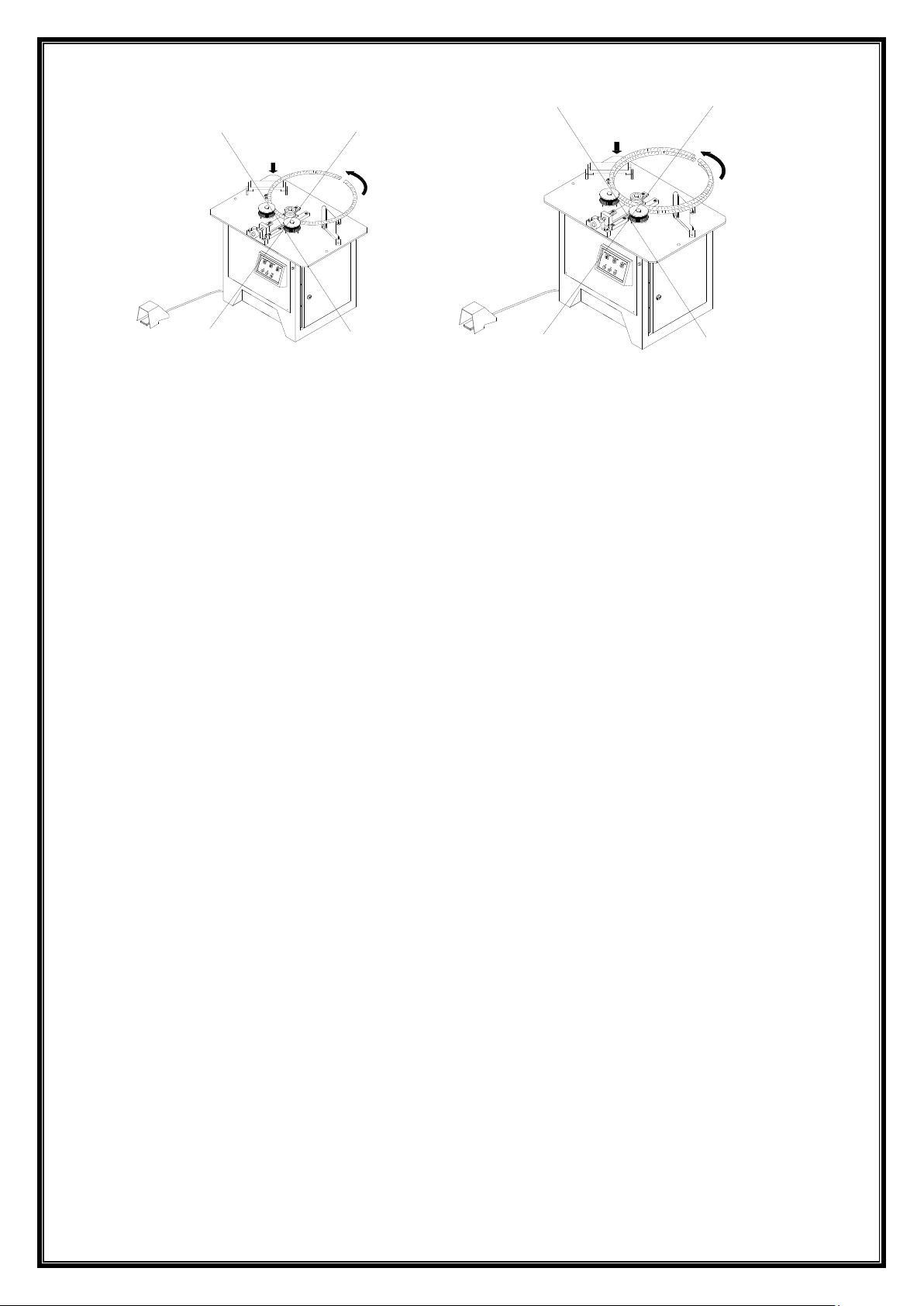
▼ Do not try to make bending material in improper forms.(Figure 3).
▼ Do not use pressurised air to clean the machine.
€ In case of need to open the lid of the power panel, ensure that main switch is to be off.
▼ Do not bend the material in multiple form, put one over another.(Figure 2).
▼ Do not allow the machine to be operated with the retainer dismantled.(Figure 3).
5. WARRANTY
The producer will only accept the warranty and responsibility subject to the following terms and
conditions:
▼ Observe all protective precautions.
▼ Observe the warning signs.
€ Do not operate the machine without grounded power.
▼ Do not replace failure parts and apparatus other than the genuine ones manufactured by
the OEM.
▼ Observe the instructions specified in the safety guidelines.
▼ Observe the guidelines for safety, and efficient use.
▼ Observe the instructions for installation.
Page 6

Rev 11/2/2020
6
▼ Observe the conditions for loading, transportation, and unloading of the machine.
▼ Operate the machine by qualified operators.
▼ Observe the measurements, dimensions and the quality of material specified in the nameplate.
▼ Use always the machine in conformance with its production purposes.
€ The power connection is to be made by a qualified electrician.
▼ Do not allow the machine to be operated when any of its part is disassembled.
€ Do not change the motor.
▼ Observe the instructions for proper service and maintenance.
▼ Follow always the instructions for proper bending forms (Figures 4, 5 and 6).
6. PROTECTIVE PRECAUTIONS
6.1 Protective Cloths
• Protective helmets
• Goggles
• Boots with steel heads.
• Gloves
Use the above protective material when you work on the machine. In case of not use these
protective materials note that there is always a risk of injury such as hand-cut and/or handcaught.
6.2. Working Garments
Note that the following are the things and garments not convenient to wear against the risk of
injury and caught during working with the machine: long hairs, dresses with long arms, identity
disks or jewellery, long working aprons etc.
7. TRANSPORTING
Utilize a forklift and/or a mobile, or a bridge-crane for transporting and lifting the machine. Use
forklifts only when the machine is in a container. Put the machine in a container using wooden
wedges under its wheels so as they do not touch on the bottom of a container, or locate it in a
container with its wheels disassembled. Use steel ropes, chains and/or polyester tackle-block
for lifting the machine. Use the lifting collets for crane hook to lift it without its container.
Employ experienced or specialized people or subcontractors for lifting purposes.
Warning!
Move the machine without causing any vibration. Do not transport it in wet conditions.
Please forward to the producer a report for the parts lost or damaged during transportation.
• Take maximum capacities of transportation and lifting machinery and equipment into your
consideration.
• Take the centre of gravity of the machine into consideration during lifting it.
Note: Observe all instructions written on the warning labels
Page 7
Rev 11/2/2020
7
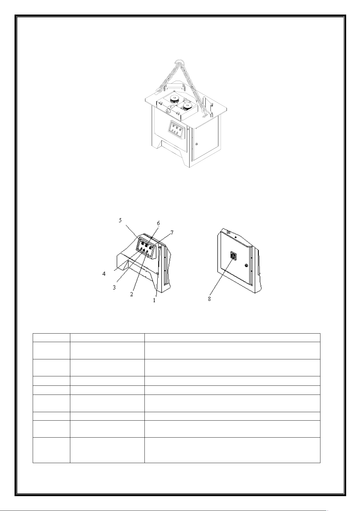
FIGURE 14
8. CHECKS AND ADJUSTMENTS
FIGURE 15
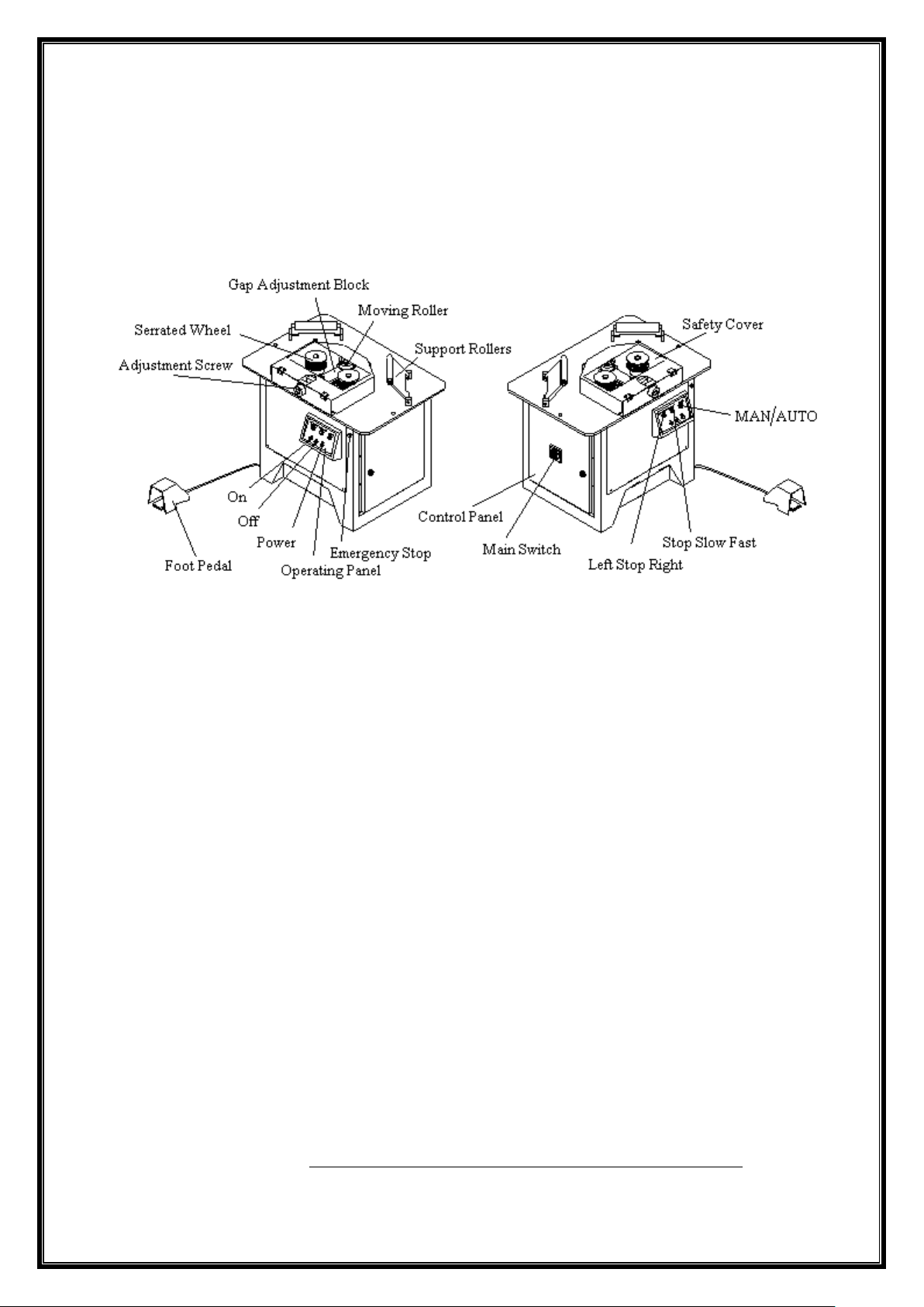
No
BUTTON
FUNCTION
1
EMERGENCY STOP
Provides the machine to be stopped in emergency by
disconnecting the power.
2
POWER LED
Indicates the power in the system is on when the
button (ON) is pressed on.
3
OFF
Ensures the machine to be stopped.
4
ON
Ensures the machine to be started.
5
LEFT/ STOP/ RIGHT
Ensures the machine to rotate to the right or left
direction.
6
STOP/SLOW/FAST
Ensures the speed of machine.
7
MAN/ AUTO
Ensures the machine to be controlled automatically
or manually.
8
MAIN SWITCH
It is such a toggle switch ensuring the power input for
the machine (0 means the machine is off, and 1 is
on.)
Page 8
Rev 11/2/2020
8
8.1 Adjustment of thermal current field, and motor circuit breaker
It is ex-works adjusted by its manufacturer as 8.6 A for 1.5 -2.5 kW motor with 750 -1.500 rpm.
(Figure 15) Do not change this adjustment. The motor circuit breaker is installed onto the
machine to de-energize the motor in order the machine not to be damaged when it takes
excessive current. Turn the switch to the position (1) for re-starting the machine in case of
circuit breaking. Under no circumstances the circuit breaker is dismantled.
Note: Should the machine be stopped by pressing the emergency stop knob turn the
MAN/AUTO switch to the MAN position and the LEFT/STOP/RIGHT switch to the reverse of
direction in that moment, and then to the direction of arrow the Emergency Stop, and press the
foot pedal and pull the material compressed out of the machine.
8.2. Bending Adjustments
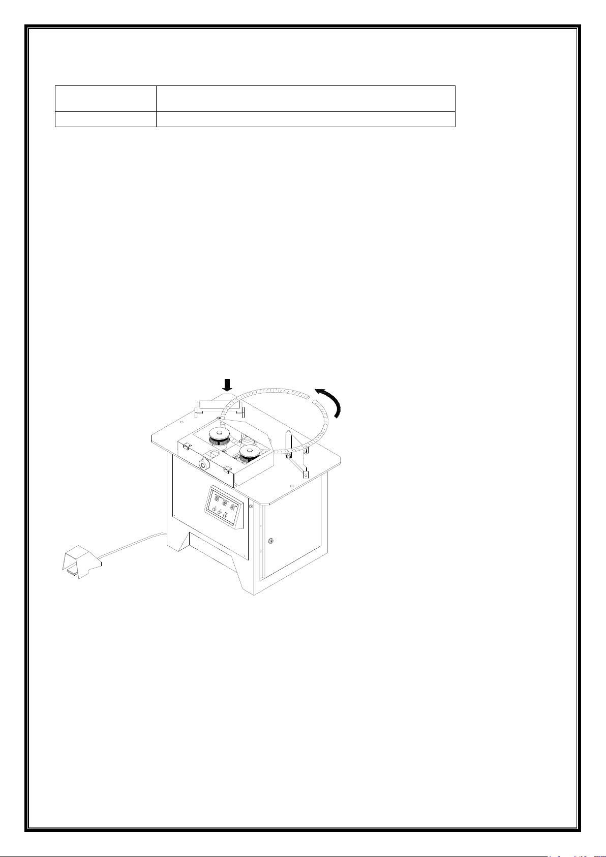
Turn the switch (MAN/AUTO) to the MAN position, close the shield and push the material to
the direction of arrow by pressing the foot pedal down. Make adjustments both in diameter and
in pitch by means of the adjustment bracket and the bending slope. Make the adjustment of
diameter by means of turning the adjustment bolt and moving the adjustment roller forward
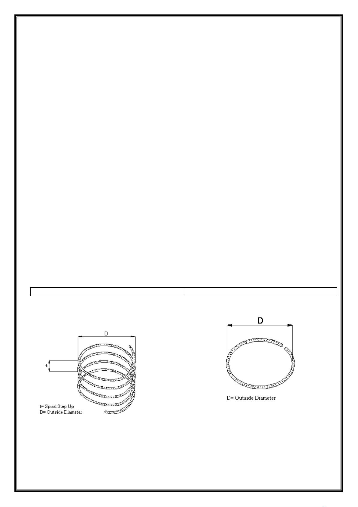
and back (Figure 4) (Closer the adjustment roller to the fixed roller smaller the diameter (D) of
the material is, and vice versa). To adjust the pitch (t) among the spiral circles lift the bending
slope (SX 36-39) up and down by means of the bolt underneath (Figure 4). Lower the slope
smaller the pitch is, and vice versa. Following the adjustments required shift the machine in
AUTO position and start to make serial bending (Figure 6).
Note: The rollers of the machine continue to turn as long as the foot pedal is pressed down.
The rotation of rollers stop if the foot pedal is stopped pressing. The rollers start to turn if the
foot pedal is pressed one time whilst the machine is on AUTO position. Press one time again
onto the foot pedal to stop it again.
FIGURE 4
FIGURE 5
FIGURE 6
Page 9
Rev 11/2/2020
9
9. MAINTENANCE AND LUBRICATION
Note that the proper maintenance is very important in order to prolong the service life of the
machine, and to ensure the bending works in safety. We recommend the users are to establish
a reliable system to control and maintain the machine. Please refer to the following instructions
when you need. Use the lubrication oil no.140 for the gearbox of the machine.
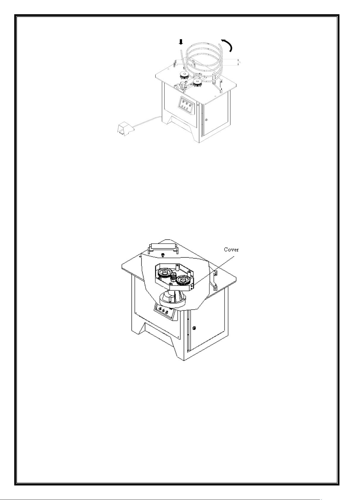
FIGURE 7
Daily Maintenance
• Clean thoroughly dust and burrs on the machine by brush.
• Use brushes to clean the top of machine.
• Check if an abnormal sound from the machine.
Weekly Maintenance
• Clean and grease the moving parts actuating the adjustment bracket.
Monthly Maintenance
• Check the bending pins and brackets. Replace the bent and/or cracked parts.
• Check if any leakage from the gearbox.
Page 10
Rev 11/2/2020
10
Biannual Maintenance
• Check and tighten all bolts and nuts of the machine.
Annual Maintenance
• Change the gearbox lubrication oil.
• Check and replace if any damaged or failure parts.
• Check and replace if any damaged or failure seals and ball bearings.
10. TROUBLESHOOTING
Refer to the Troubleshooting Chart below for the failures, errors and/or troubles, which may be
take place during utilization of the machine.
Warning! Disconnect first the power by turning the main switch to the (0) position in
case of a need to open the lid of power panel for troubleshooting. Do not allow the
people other than a qualified electrician to make a check and/or a repair in the power
panel.
NO
SYMPTOM
POSSIBLE CAUSE
SOLUTİON
1.
Machinery fails to
operate.
1. Power supply is interrupted
and/or one of the phases is
short.
2. Emergency stop knob is
remained pressed.
3. Protection switch is cut-out
4. The Left/Stop/Right switch is
closed.
5. The lid of power panel is
opened or is not closed
properly.
6. The STOP SLOW FAST
switch is on the STOP
position.
1. Check power supply and
phases.
2. Check the knob. To open
turn it to the arrow direction on
the knob if it is remained
pressed.
3.Check protection switch. Turn
it to Position (1) if it is off.
4. Check the switch. Turn it to
right or left if it is on the stop
position.
5. Check the power panel lid.
6. Check the switch. Turn it to
the position required.
2.
Protection switch cutsout continuously.
1. Diode is burned.
2. Motor is burned.
3. Machine bends material with
larger diameter than its
capacity.
4. Short phase in power supply.
5. Transformer is burned.
6. Short circuit or damage in
1. Check the diode.
2. Check the motor.
3. Check the material in
accordance with the information
about the kind of material and
dimensions on the nameplate.
4. Check the phase of power
network.
5. Check the transformer.
6. Check the cable and
Page 11

Rev 11/2/2020
11
cables.
connections
3.
Machinery fails to
operate despite the
foot pedal is pressed.
1. The plug is off.
2. The pedal is defected.
3. Contactors in electrical
system are defected.
1. Check the plug.
2. Check if the pedal is
defected.
3. Check the contactors in the
electrical system.
4.
Emergency stop does
not operate.
1. The emergency stop
contactor is defected.
2. Cable connections are off.
1. Replace the emergency stop.
2. Check the cable connections
5.
Abnormal sound
comes out.
1. Ball-bearings are worn out.
2. Impeller touches with the
bonnet.
3. Gears are broken.
4. No oil left in the gearbox.
5. Short phase in power supply.
6. Machine operates
overcapacity.
7. The brake in electro
magnetic machines does not
open or the broken lining of
brake touches.
1. Check the ball-bearings
2. Check the impeller bonnets.
3. Check the gears
4. Check the gearbox oil.
5. Check the phases
6. Check the material in
accordance with the
dimensions on the nameplate.
7. Check the brake and linings
if they operate properly.
7.
Oil leakage from the
machine
1. The air ventilation plug of
gearbox is not installed.
2. The packing O-ring of motor
leaks
3. The fixing bolts of the
gearbox are loose.
1. Check if the plug is screwed.
2. Check the motor from the
impeller side. Replace the
packing O-ring if it leaks.
3. Check and tighten all fixing
bolts.
Page 12
Rev 11/2/2020
12
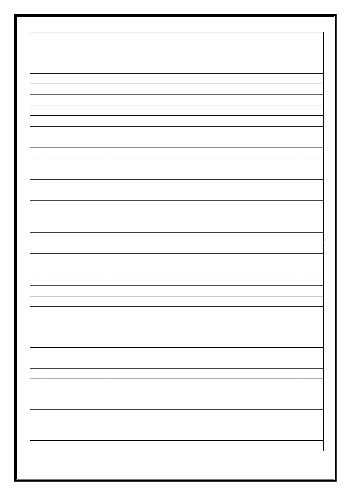
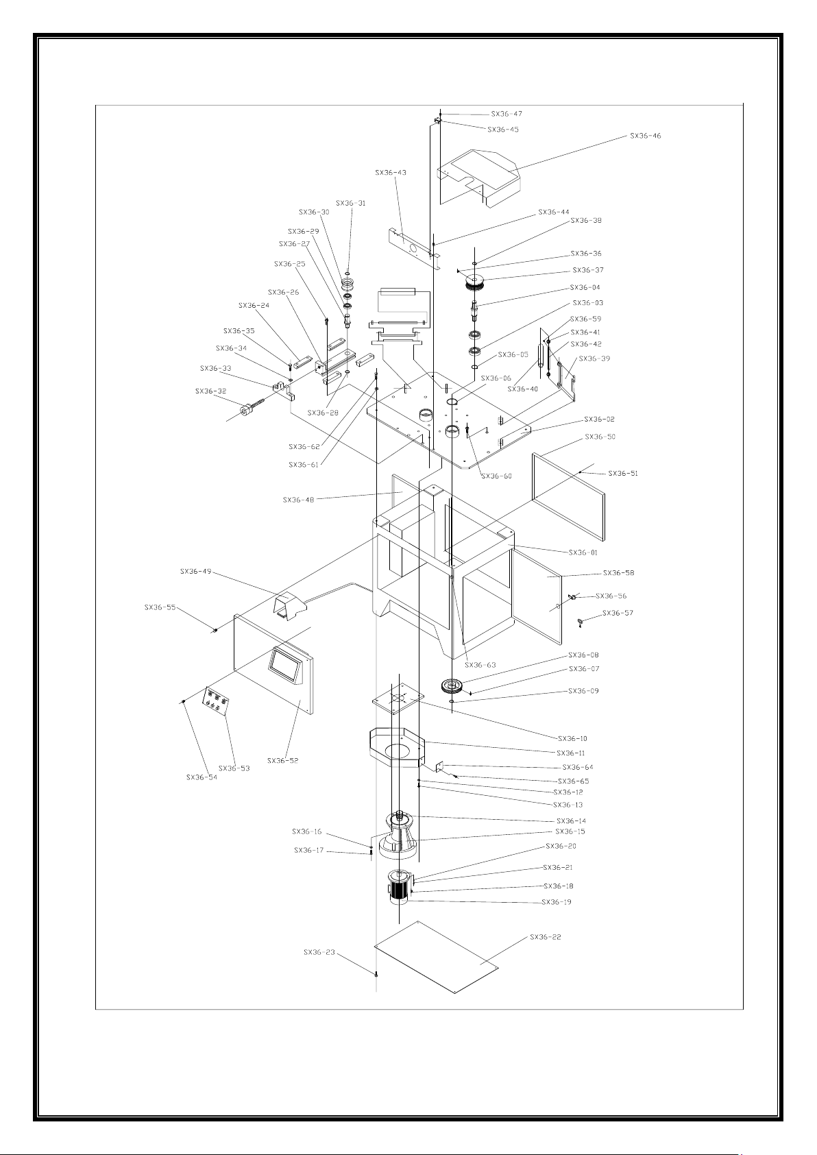
PARTS LIST
No
Part Numbers
PART NAME
UNIT
1
SX 36-01
HOUSING
1
2
SX 36-02
TABLE PLATE
1
3
SX 36-03
BEARING 6213 ZZ
4
4
SX 36-04
AXLE
2
5
SX 36-05
Ø 65 AXLE RING
2
6
SX 36-06
Ø 120 HOLE RING
2
7
SX 36-07
Ø WEDGE 12x8x45 DIN 6885
2
8
SX 36-08
GEAR Z=63 Mn=3
2
9
SX 36-09
Ø 40 AXLE RING
2
10
SX 36-10
REDUCER CONNECTION FLANGE
1
11
SX 36-11
BELOW PROTECTIVE PLATE
1
12
SX 36-12
M16 SPRING WASHER DIN 1440
4
13
SX 36-13
M16x40 BOLT 8,8 DIN 933
4
14
SX 36-14
PINION GEAR Z=25 MN=3
1
15
SX 36-15
REDUCER
1
16
SX 36-16
M10 SPRING WASHER DIN 1440
4
17
SX 36-17
M10x30 BOLT 8,8 DIN 933
4
18
SX 3618
WEDGE 8x7x51DIN 6885
1
19
SX 36-19
MOTOR
1
20
SX 36-20
SPRING WASHER DIN 1440
4
21
SX 36-21
BOLT
4
22
SX 36-22
BELOW PROTECTIVE COVER
1
23
SX 36-23
M10x15 BOLT 8,8
4
24
SX 36-24
CONNECTION THRUST
4
25
SX 36-25
M12x30 BOLT 8,8 DIN 912
8
26
SX36-26
ADJUSTMENT THRUST
1
27
SX 36-27
AXLE
1
28
SX 36-28
Ø 40 AXLE RING
1
29
SX 36-29
BEARING 6210 ZZ
2
30
SX 36-30
MOBILE ROLLER
1
31
SX 36-31
Ø 50 AXLE RING
1
32
SX 36-32
ADJUSTMENT SCREW
1
33
SX 36-33
CHANNEL
1
34
SX 36-34
M 16 SPRING WASHER DIN 1440
2
35
SX 36-35
M16x50 BOLT 8,8 DIN 933
2
36
SX 36-36
WEDGE 14x9x45 DIN 6885
2
Page 13
Rev 11/2/2020
13
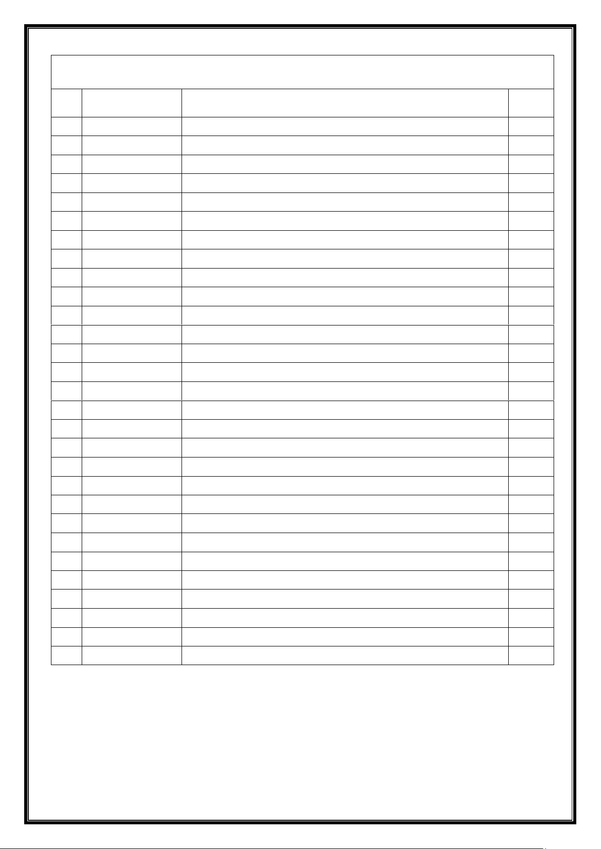
PARTS LIST
No
PART NUMBER
PART NAME
UNIT
37
SX 36-37
STABLE ROLLER
2
38
SX 36-38
Ø 50 AXLE RING
2
39
SX 36-39
LAUNCHING PAD
2
40
SX 36-40
STEEL ROLLER
2
41
SX 36-41
BEARING 6003 ZZ
4
42
SX 36-42
ROLLER AXLE
2
43
SX 36-43
PROTECTIVE CONNECTION PLATE
1
44
SX 36-44
M16x15 BOLT 8,8 DIN 7991
2
45
SX 36-45
HINGE
2
46
SX 36-46
PROTECTIVE COVER
4
47
SX 36-47
M6x15 BOLT 8,8 DIN 7991
1
48
SX 36-48
ELECTRIC PANEL
1
49
SX 36-49
FOOT PEDAL
1
50
SX 36-50
MAINTANANCE COVER
1
51
SX 36-51
M6x30 BOLT 8,8 DIN 7991
4
52
SX 36-52
HEAD PANEL COVER
1
53
SX36-53
CONTROL PANEL COVER
1
54
SX36-54
M6x15 BOLT 8,8 DIN 7991
4
55
SX 36-55
M6x30 BOLT 8,8 DIN 7991
4
56
SX 36-56
PANEL LOCK
2
57
SX 36-57
KEY
1
58
SX 36-58
PANEL COVER
2
59
SX 36-59
M8x10 BOLT 8,8 DIN 417
1
60
SX 36-60
M12x30 BOLT 8,8 DIN 933
2
61
SX 36-61
M10 SPRING WASHER DIN 1440
4
62
SX 36-62
M10x30 BOLT 8,8 DIN 933
4
63
SX 36-63
EMERGENCY STOP
1
64
SX 36-64
COVER
1
65
SX36-65
M6x10 BOLT 8,8 DIN 933
2
Page 14
Rev 11/2/2020
14
Page 15
Rev 11/2/2020
15
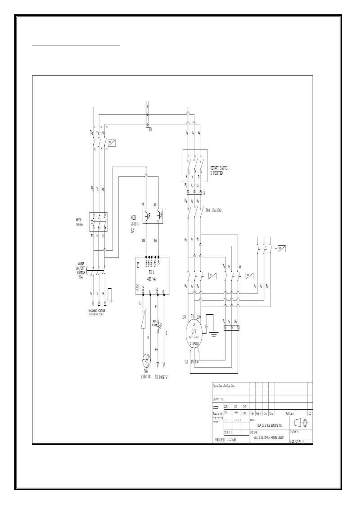
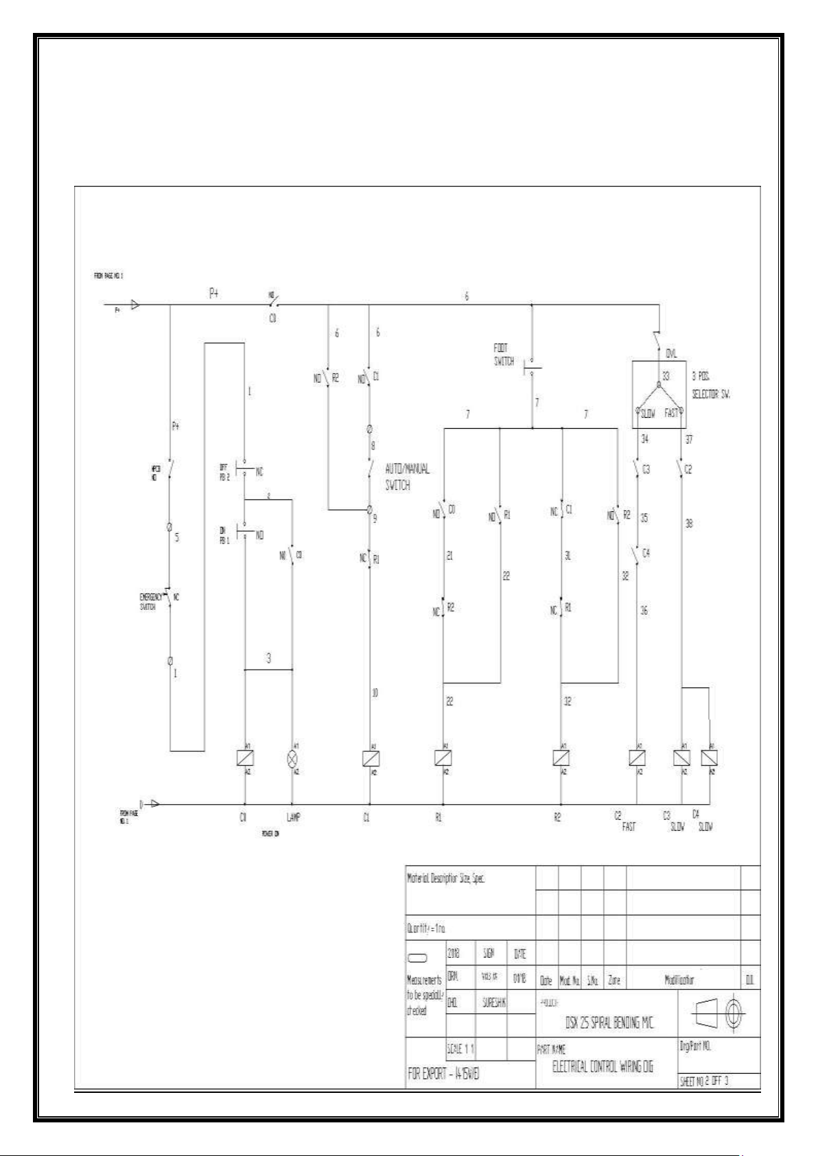
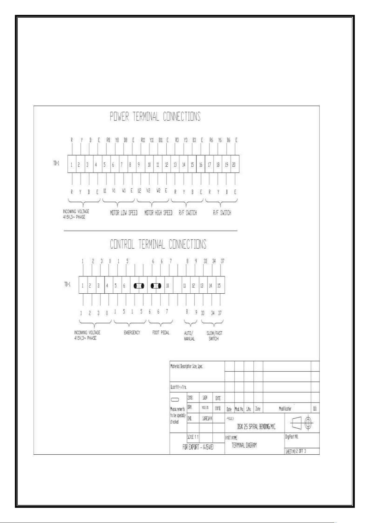
ELECTRICAL DRAWINGS
Page 16
Rev 11/2/2020
16
Page 17
Rev 11/2/2020
17
 Loading...