

Page 1
DBD-20M TM.indd • ©BN Products-USA, LLC. • (800) 992-3833 • [email protected]
Bender Handling Instructions
DBD-20M 0-180 degree
Portable Rebar Benders
BN Products-USA, LLC.
3450 Sabin Brown Road
Wickenburg, AZ 85390
(800) 992-3833 • (928) 684-2813
FAX: (928) 684-7041
[email protected]
www.bnproducts.com
Products that make money, save money and add value to your bottom line
Page • 1
Page 2
Bender Handling Instructions
DBD-20M Rebar Benders (0-180 degree)
Important: When using electric tools, basic safety precautions should always be
followed to reduce the risk of electric shock and personal injury, please note the
followings items:
READ ALL INSTRUCTIONS AND SAVE
THIS DOCUMENT FOR REFERENCE.
1. Keep hands away from all moving parts and rollers while operating.
2. Dress properly. Loose clothing or jewelry can
get caught in moving parts. Wear sturdy boots
with non-skid soles. Steel toed boots and safety
glasses are recommended.
3. Keep children and bystanders away. Distractions
can cause you to lose control.
4. Do not overreach. Keep proper footing and balance at all times. is enables better control of
the power tool in unexpected situations.
5. Stay alert. Watch what you are doing and use
common sense when operating a power tool. Do
not use a power tool while you are tired or under
the inuence of drugs or alcohol. A moment of
inattention while operating power tools may result in serious personal injury.
6. Do not exceed the maximum number of bars
that can be bent at one time. Please refer to the
Rebar Bender Roller Selection Chart
9. Do not try to bend materials harder than “Grade
60 or 600N/mm2” as they will either crack and
y out or cause machine failure.
10. Disconnect tool from receptacle when not in use.
Disconnect the tool when servicing or changing
rollers to prevent accidents.
11. Keep tool clean at all times for best and safest
performance. Follow instructions for lubricating and changing parts. Keep hands dry and
free of oil or grease. Inspect switches, tool cords
periodically and have them repaired or replaced
by an authorized service center if damaged.
Check moving parts for alignment and binding
as well as for breakage and improper mounting. Damaged parts should be repaired or replaced by an authorized service facility unless
otherwise indicated in this instruction book.
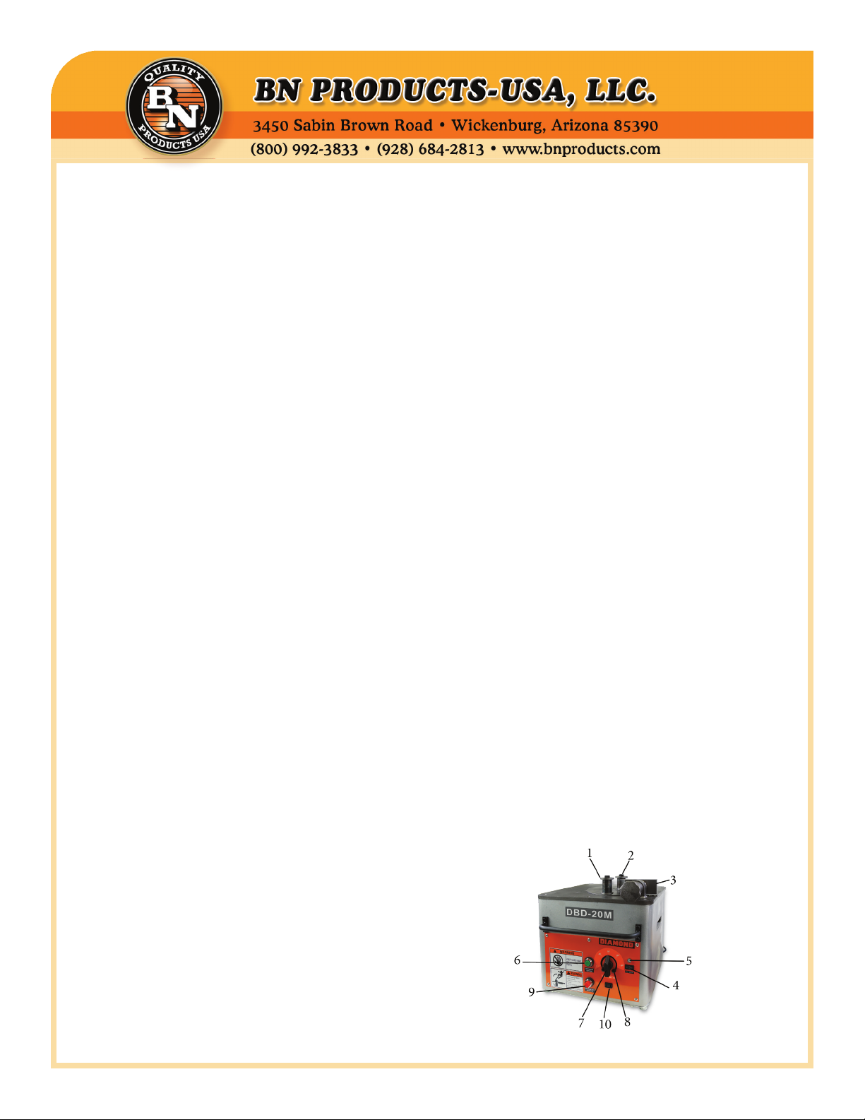
1. Moving bending roller
2. Center roller
3. Adjustable stopper
4. Main switch
5. Pilot lamp
6. On/O Button
7. Angle setter (dial type)
8. Angle stopper (Le &
Right)
9. Emergency stop button
10. Plug-in for foot switch
11. Roller set (not shown)
12. Foot Operated Switch
(not shown)
7. When positioning the bar between rollers, make
sure to lay it at on the machine surface. Failure
to do so may cause the rebar to y out.
8. Do not expose tool to rain or use in damp locations. Do not use tool in presence of ammable
liquids or gases. Keep work area well lit. If the
tool is used outdoors, keep it covered when not
in use and protect it from rain or water.
Products that make money, save money and add value to your bottom line
Page • 2
Page 3

SPECIFICATIONS
Model DBD-20M
Max. Bending
Capacity
Bending Angle 0-180°
Bending Speed 7 seconds for a
Electric Power
Supply
Dimensions
L x W x H (mm)
Weight (Kg) 134.5 lbs (61)
Rebar Diameter Size Center Roller Moving Roller # of Grade 60 Rebar Bent
# 6 (3/4”) (19mm) # 4 (3.71” diameter) # 2 (2.65” diameter) 1 piece at one time
# 5 (5/8”) (16 mm) # 4 (3.71” diameter) # 3 (2.93” diameter) 2 pieces at one time
# 4 (1/2”) (13 mm) # 3 (2.93” diameter) # 5 (3.90” diameter) 3 pieces at one time
# 3 (3/8”) (10 mm) # 1 (2.22” diameter) # 6 (4.80” diameter) 4 pieces at one time
3/4” (# 6) (19 mm)
Grade 60 Rebar
180° bend
115 Volts, 50/60 Hz, 15
amps, 1725 watts
16.4” x 18” x 16.2”
(420) x (462) x (415)
DBD-20M Rebar Bender Roller Selection Chart
PLEASE NOTE: CRSI (Concrete Reinforcing Steel
Institute) recommends the nished inside bend diameter or center roller outside dimension for standard hooks be 6 times the bar diameter from #3 to
#8, and 8 times the diameter for #9, #10 and #11 rebar. For #3, #4 and #5 stirrup hooks it’s only 4 times
the bar diameter, #6, #7 and #8 are again 6 times.
CHANGING ROLLERS OR ACCESSORIES.
WARNING: ALWAYS UNPLUG TOOL
BEFORE CHANGING ROLLERS
1. Select and set the correct rollers for the bars to
be bent. See Rebar Bender Roller Selection
Chart
2. Plug the electrical power cord into an appropriate outlet.
3. Lay the bar on the machine surface between
the center roller and bending roller. Adjust the
stopper so that the bar is parallel to the front
edge of the machine.
4. Turn the main switch on and check that the
pilot lamp has lit up.
5. Set the angle and make a test bend. If the bent
angle is not exact, adjust the angle setter slightly
to the right or le. Lock in the angle stoppers to
duplicate the same angle each time.
6. Push the operation button or foot switch. e
moving bending roller will automatically return
to the start position once the bend has been
completed.
7. If it is necessary to stop the machine in an
emergency, push the emergency stop button or
release your foot from the foot operated switch.
e bending roller will return to the start position automatically.
Products that make money, save money and add value to your bottom line
Page • 3
Page 4
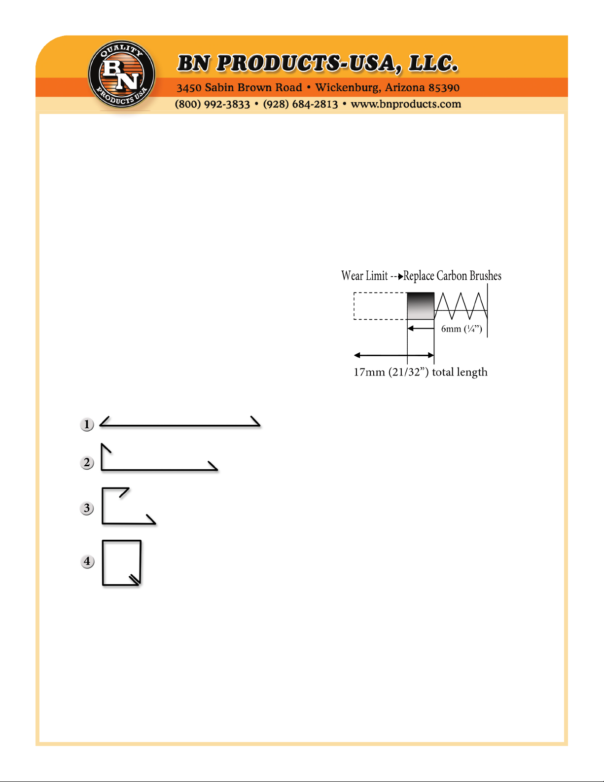
BENDING ANGLES CAN BE PRESET
1. Set the angle setter to 135° then tighten the
right angle stopper to lock the 135° position.
2. Set the angle setter to 90° then tighten the le
angle stopper to lockthe 90° position.
3. Set the angle setter to 135°. Push the operation
button to make your rst bend.
4. Slide the rebar to the desired length and set the
angle setter to 90°. Push the operation button to
complete your second bend.
For stirrups, cut your rebar to the desired length
before bending. en make both bends for your
turndowns. Finally make your (3) 90° bends to connect your ends together. See chart (below)
WARNING: Never touch any moving parts or rollers while the rebar bender is being operated.
DO NOT USE PARTS OR ACCESSORIES THAT
ARE NOT GENUINE DIAMOND BRAND
FROM: BN PRODUCTS-USA, LLC.
At least once a month remove the bottom plate and
grease all the visible gears and pinions. At the same
time, check the carbon brushes for wear or damage.
Replace with new brushes if they are worn out.
(wear limit→replace carbon brushes)
INSPECTION AND MAINTENANCE
WARNING: ALWAYS UNPLUG TOOL
BEFORE PERFORMING MAINTENANCE.
1. Check that there are no loose nuts and bolts
before starting the operation.
2. Aer operation is completed, be sure to remove
metal dust, dirt, oil, etc… adhering to the machine surface.
3. In order to empty the metal dust from the
bender, remove side cover (DBD-25X and
DBD-32X models) then tilt the machine to one
side allowing the debris to fall out of the catch
pan. Be sure to blow out any remaining dirt
and dust with compressed air prior to using the
tool again (wear safety goggles to block blowing
debris).
CUSTOMER SERVICE:
(800) 992-3833
Products that make money, save money and add value to your bottom line
Page • 4
Page 5
Products that make money, save money and add value to your bottom line
Page • 5
Page 6
Page • 6
Page 7
2
4
1
2
1
1
1
2.3
52 7SW002.3 SPRING WASHER
2
53 1BL51028600 GEAR CASE (A) 1
CRESCENT TYPE
54 1BL5100300 GEAR CASE (B) 1
55 7CW08035 CAP BOLT M8X35 4
5103-18
56 7CB10110 CAP BOLT
1
62072RS
M10X110
57 7GW010 WASHER 10 4
58 76006ZZ BEARING 6006ZZ 1
1
RING 72 FOR
HOLE
2.5KW
TND14V-
471KB00AAA0
59 7K0606012R2 KEY 6X6X12 1
60 1BL5400502 PINION (1) 1
61 1BL5400402 GEAR (1) 1
62 7SRS020 SNAP RING 1
63 76902ZZ BEARING 6902ZZ 1
64 76004ZZ BEARING 6004ZZ 1
65 7K0505028R1 KEY 5X5X28 1
66 1BL5400802 PINION (2) 1
67 76002ZZ BEARING 6002ZZ 1
68 1BDL401162 CLUTCH TMC
1
ER 5
1
M10X35
69 7TND14V471K VARISTOR
1
1
10
10
70 1BDL400280 COLLAR 1
1
62122RS
71 1BDL400242 CLUTCH GEAR 1
1
RING 37 FOR
72 76904ZZ BEARING 6904ZZ 2
73 7SRH037 S TYPE STOP
SUPPORT
HOLE
2
SS5GL2
74 1BL5400700 CLUTCH COLLAR 1
4
75 7FU02SC FINE U NUT 1
76 7CB05080 CAP BOLD M5X80 1
M2.3X15
ER 5
77 7N005 NUT M5 1
78 7SW005 SPRING WASH-
1
1
RING 30 FOR
SHAFT
RING 25 FOR
79 76203ZZ BEARING 6203ZZ 2
80 7SRS025 S TYPE STOP
2
STAY
HOLE
M4X8
28 7CB05018 CAP BOLT 5X18 1
No. Part No. Part Name Qty
29 76205ZZ BEARING 6205ZZ 1
1 1BL51028500 FRAME 1
30 76207ZZ STOPPER
2 1BL5303401 HANDLE 2
3 7CB08020 CAP BOLT M8X20 4
31 762072RS BEARING
32 7SRH072 C TYPE STOP
4
SPRING 8
4 7NS008 NUT W/DISC
5 7CB08015 CAP BOLT M8X15 4
33 1BL54265400 SHAFT COLLAR 1
34 1BL5403200 LS DOCK 1
35 7PW005 PLATE WASHER 5 1
36 7SW005 SPRING WASH-
37 7CB05008 CAP BOLT M5X8 1
38 1BL5402200 SPRING COLLAR 1
39 1BL53136700 RETURN SPRING 1
40 7CB10035 CAP BOLT
41 7SW010 SPRING WASHER
42 7PW010 PLATE WASHER
43 762122RS BEARING
44 1BL5401700 MAIN SHAFT
45 1BL9404400 ANGLE GEAR (B) 1
46 7SS5GL2 LIMIT SWITCH
47 7PB2.3015 TAPPING SCREW
48 7N002.3 NUT M2.3 2
49 7SRS030 C TYPE STOP
4
6 1BL5402801 BRUSH COVER 2
7 7PB08015 PAN HEAD BOLT
M8X15
8 1BL51028700 BASE PLATE 1
7
M10X20
9 7CB10020 CAP BOLT
1
ING TAF243220
10 7TAF243220 NEEDLE BEAR-
1
1
RUBBER (KI-40)
ER 8
11 7KI40 ANTI-VIBRATION
12 7SW008 SPRING WASH-
13 7N008 NUT M8 1
1
STOPPER
14 1BL54265800 ADJUSTABLE
1
1
NUT S45C50X74
15 1BR5064 ADJUSTABLE
16 1BR5065 ADJUSTABLE
2
HANDLE
M5X8
17 7SP05008W SPRING PIN
3
M12X25
18 1BL54265600 CENTER COVER 1
19 1BL54265700 CENTER PLATE 1
20 7SB06015 CAP BOLT M6X15 1
21 1BL5402000 WASHER 3
22 7B12025T11 BOLT (11T)
50 1BL5403102 OVERRUN LS
1
23 1BL5101503 SWIVEL GEAR 1
24 1BL54265300 SWIVEL SHAFT 1
25 7SW012 SPRING WASHER
51 7SS04008 SET SCREW
12
26 1BL53136600 MAIN SHAFT 1
27 1BL54265200 KEY (4) 1
Page • 7
Page 8
1
1
SWITCH ABS110N
STOP SWITCH
140 7ABS110N START-UP
141 7ABS201NR EMERGENCY
142 7ACT03FB03 OUTLET 1
143 7NB106PWF PILOT LAMP 1
144 7AJ8101B MAIN SWITCH 1
145 1BL53136800 BOTTOM PLATE 1
146 7B206012 BOLT M6X12 10
1
DBD20M STAND
SET
Not Shown
* 1BL52071400AS
1
1
ROLLER SET
(DBD20M) (20M)
FOOT SWITCH
OFL-55SM2C W/
PLUG
Not Shown
Not Shown
* 1BL54035ST
* 1BDL401190A
6
M5X8
110 7P205008 TAPPING SCREW
111 7P445701H01 COVER 1
112 7P443817H01 RUBBER PIN 1
113 1BL9303802 ANGLE STAND 1
1
(B)
114 1BL9404200 ANDGLE SHAFT
1
115 7K0404010R2 KEY 4X4X10 1
116 1BL9403900 ANGLE PLATE 2
2
M4X20
117 7SP04020W SPRING PIN
118 1BL9404300 ANGLE GEAR (A) 1
119 7SRS012 SNAP RING 1
1
1
M4X16
120 7N008 NUT M8 2
121 7PW008 PLATE WASHER 8 2
122 7WW008 WAVE WASHER 8 1
123 1BL54265900 ANGLE SHAFT (A) 1
124 1BL9405900 ANGLE SPRING 1
125 1BL9404100 ANGLE COLLAR 1
126 7SS04004 SET SCREW 4X4 1
127 7NT304016 TAPPING SCREW
128 7AG1610B CABLE GRAND
1
2
1
(AG16-10B)
AC100
129 1BDL401180 CORD W/GRIP 1
130 7G7J4AT RELAY G7J4AT
2
4
M4X12
131 7R9904 BRACKET R99-04 1
132 7P304012 TAPPING SCREW
133 7ORM0309FS CLUTCH POWER 1
1
2
134 1BL52070300 CONTROL PANEL 1
135 7TS05010 SCREW M5X10 6
136 1BL5404200 ANGLE PLATE 2
137 7YB05015 BUTTON SCREW
1
M5X15
138 1BL9404501 ANGLE SETTER 1
2
2
M5X10
139 7SS05010 SET SCREW
No. Part No. Part Name Qty
RING 30 FOR
SHAFT
81 1BL5400902 GEAR (2) 1
82 7K0807015R2 KET 8X7X15 1
83 1BL5401002 PINION (3) 1
84 76204ZZ BEARING 6204ZZ 1
85 7SRS030 C TYPE STOP
86 1BL5401202 GEAR (3) 1
87 7K1008023R2 KEY 10X8X23 1
88 1BL53136500 PINION (4) 1
89 76909ZZ BEARING 6909ZZ 1
90 7V40S V RING (40S) 1
91 7CB06025 CAP BOLT M6X15 2
92 7GW006 WASHER 6 2
93 7CB05020 CAP BOLT M5X20 2
BLY 95 - 112
94 7GW005 WASHER 5 2
95 7UML8 MOTOR ASSEM-
96 76202ZZ BEARING 6202ZZ 1
97 7M315320G01 ROTOR (100V) 1
M5X100
98 76200ZZ BEARING 6200ZZ 1
99 7PB05100 TAPPING SCREW
100 7SW005 SPRING WASH-
ER 5
Φ6X110
101 7P304229H01 FAN GUIDE 1
102 7P850966H01 BRACKET 1
103 7M315321G01 STATOR (100V) 1
104 7WT06110 VARNISH TUBE
105 7P504595H01 BRUSH CAP 2
BRUSH HOLDER
106 7P442416G01 BRUSH 2
107 7P445180G01 FLAME SET W/
M3X6
108 7P203006BS TAPPING SCREW
109 7P858310H01 END COVER 1
Page • 8
 Loading...