

Page 1
3450 Sabin Brown Road • Wickenburg, AZ 85390
(800) 992-3833 • [email protected]
Operating Manual
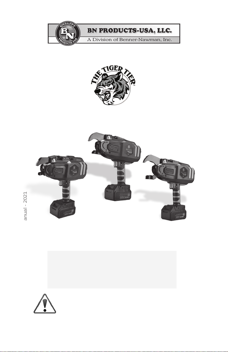
BNT-25X • BNT-40X • BNT-58X
DIGITAL DISPLAY SERIES
International Quality System Certication
The charger has passed ETL Certication
BNT-Tiger Tier-Operations Manual - 2021
Please read this manual carefully before using these
machines to make sure you are familiar with all safety and
warning instructions.
This tool has
passed ISO9001
Page | 1
Page 2
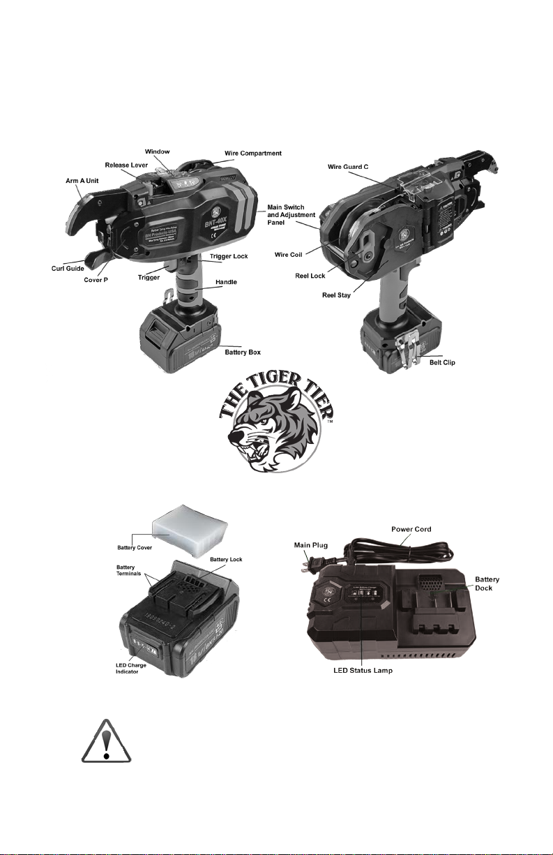
BNT-Series Tiger Tier™
Callouts
Battery Charger
Please read this manual carefully before using these
machines to make sure you are familiar with all safety and
warning instructions.
Page | 2
Page 3

Safety First
• This machine is a high-performance battery-operated tool. Failure to follow the
warnings and instructions may result in an electric shock, re, or serious injuries.
• Always operate the tool with personal protection equipment (including eye protec-
tion, etc.). Using the appropriate safety equipment at all times will avoid injury.
• Keep children and bystanders away while operating this tool. Distractions may
cause serious accidents. Do not aim the tool at those standing around your work
area. Serious accidents can happen if you mishandle this tool.
• Do not place your hand or position the machine near your body. Doing this could
cause serious injury.
• Do not attempt to dismantle, modify or perform any major maintenance on this tool.
Modications may deteriorate the tool’s performance and may cause severe injury,
and void the warranty.
• Ensure that the main switch is o when the tool is not in use or when abnormalities
occur. For example, when changing or adjusting the wire coil or when changing the
battery pack, make sure to turn o the main power switch and lock the trigger or
remove the battery.
• Do not place ngers or hands in the wire coil area. Doing so may cause injury.
• Do not operate this tool in the rain or areas where moisture is present. Doing so
may result in electrical shock or accident.
• Stay particularly alert while working in a high area. Do not operate any power tool
under the inuence of drugs, alcohol, or medication. A moment of inattention may
result in serious injury to you or someone near you.
• Do not operate this tool in a hazardous area containing ammable liquid, gas, or
powders that may ignite and cause a re.
• The charger unit uses standard AC power (100-240V ~ 50-60Hz). Do not recharge
the battery using a gas generator power supply, as this will cause the electronic
charger to malfunction.
• Our batteries charge best when the ambient temperature is between 32°F and
113°F. Therefore, Super-cooling or over-heating environments are not suitable for
charging.
• Continuous use of the charger is not advised. This will shorten the battery’s life
span and the charger’s performance. When not in the charging mode, the power
supply must be unplugged.
• Please do not carry the charger by the cord. Also, do not pull out the power cord
from the wall socket with the cord. This will damage the cord and break the wires or
cause a short circuit. A damaged cord must be repaired or replaced immediately.
• Use only the specied charger that came with your machine. Using an unauthorized
charger may result in damage to the battery components and a possible explosion.
• Avoid battery terminal contact with other metal objects. For example, trying to recharge the battery with an external wire could result in a short battery circuit.
• Do not throw away the protective battery cap. Use it to cover the terminal when not
in use
Page | 3
Page 4
Safety Locks
Make sure that all safety features are operational before using any power tool.
DO NOT OPERATE THE TOOL IF THE SAFETY LOCKS ARE NOT FUNCTIONAL.
This tool is equipped with the following safety devices:
• The Main Switch: Please turn the main switch o when not in operation.
• The Trigger Lock: Always engage the trigger lock when not in use or when changing the wire spool.
Technical Data
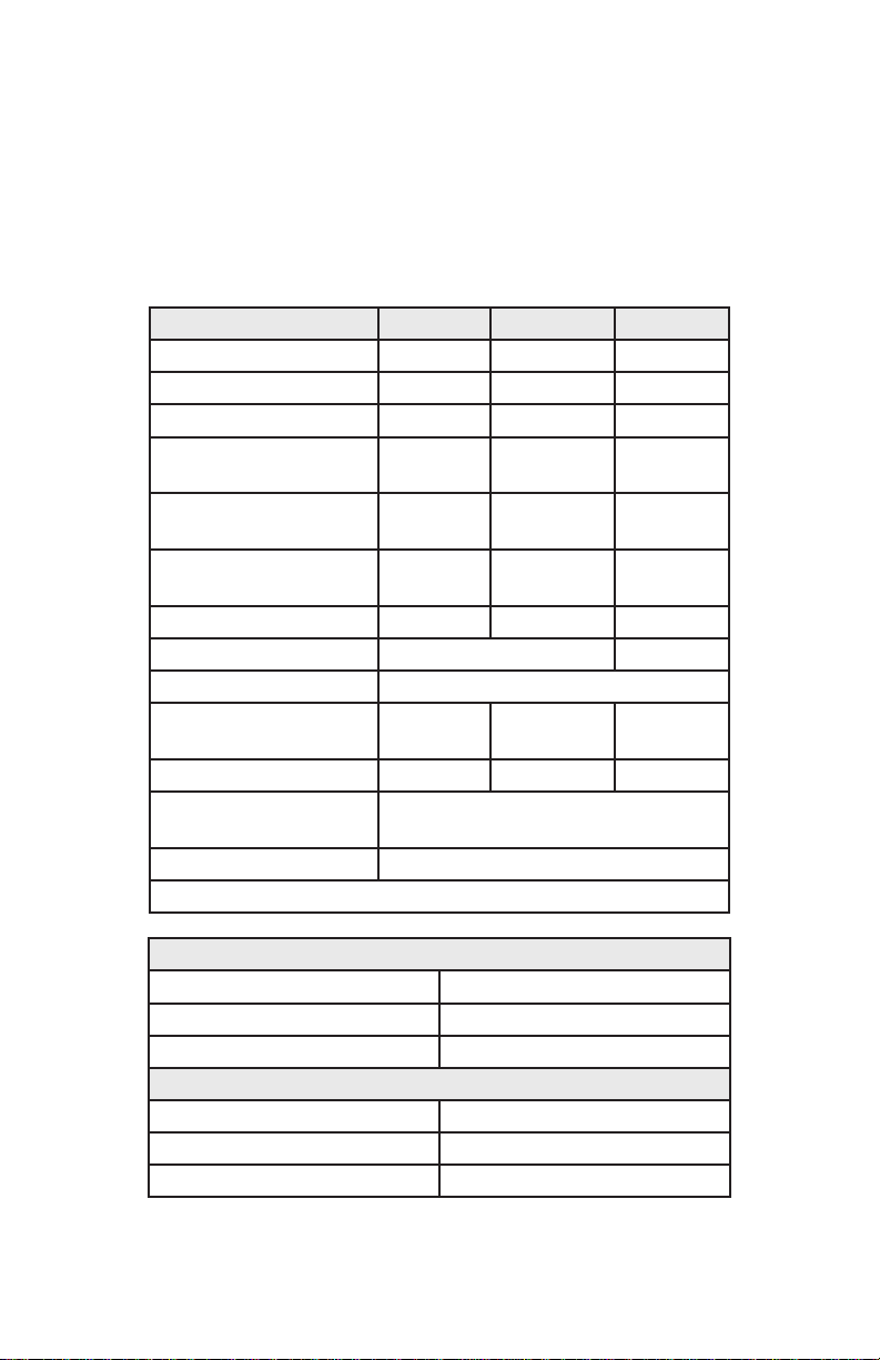
Product No. > BNT-25X BNT-40X BNT-58X
Tool Only 4.15 lbs. 4.45 lbs. 4.85 lbs.
Tool + Battery 5.5 lbs. 5.8 lbs. 6.2 lbs.
Tool + Battery + Wire 6.4 lbs. 6.7 lbs. 7.1 lbs.
Height 11.81”
(300mm)
Width 4.29”
(109mm)
Length 11.06”
(281mm)
Ties per spool 160-220 120-160 85+
Wraps per tie 3 Wraps 4 Wraps
Time per tie 0.6-0.8 Seconds
Max tying diameter 1” (25mm) 1.575”
#3 x#4 #6x#6 #8x#8
Battery Li-Ion 18V, 4.0Ah, 72Wh
(BNTLI-20)
Ties per charge 4000-5000
Additional Charger (BNTLI-20C)
11.81”
(300mm)
4.29”
(109mm)
1 1.69” (297)
mm)
(40mm)
12.2” (310
mm)
4.29”
(109mm)
12.28”
(312mm)
2.283”
(58mm)
BNT-40-Wire
Diameter (in.) ø 0.03 (21 Gauge)
Material Q195 Galvanized
Length (in.) 3937 (approx)
BNT-40-Wire-USA
Diameter (in.) ø 0.03 (21 Gauge)
Material Q195 Black Annealed Wire
Length (in.) 3937 (approx)
Page | 4
Page 5
BNT-40-Wire-P
Diameter (in.) ø 0.03 (21 Gauge)
Material Q195 Polycoated
Length (in.) 3937 (approx)
Battery and Charger Usage
Before inserting or removing the battery from this tool, please set the main switch to the
o position.
• To avoid a short circuit to the battery, always use the battery terminal cover when it
is not in use with the tool.
• When placing the battery into the tool, press the battery lock before placing it into
the battery holder. When removing the battery, press the battery lock button before
pulling it out of the battery holder.
• Use 100-240V ~ 50-69Hz AC power supply for the charger. Fully insert the battery
into the charger slot and it will begin to charge automatically as indicated by the
charging light. It will take approximately 74 minutes to fully complete the battery
charge.
• It is recommended to charge the battery between 32°F and 113°F. Do not charge in
extreme cold or hot environments.
Machine Operation and Methods
• Before inserting or removing the wire spool turn the main power switch to o and
lock the trigger.
• When installing the wire spool in this tool only use recommended wire that is clean
and rust free.
• Only use recommended wire spools. Using non-standard wire or spool could cause
the tool to malfunction.
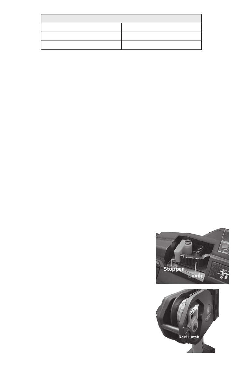
• Press and lock the lever.
• Push the Reel Stopper to release the Reel Stay
(door) and open.
• Cut about 2 inches of wire o the end of the coil.
• Install the wire spool with the left side facing the
tool (left is marked on the spool). Close and latch
the Reel Stay (door).
• Insert the wire into Wire Guide C. Note: the wire
must not be bent or curved.
• The wire must pass through Wire Guide C and in
between the two feeding gears until it reaches the
ared tube. Then push the wire an additional ½ inch
into the ared tube.
• Release the Release Stopper and conrm the
Release Lever has returned to its original position.
Note: the wire must be clamped in between the
feeding gears.
Page | 5
Page 6
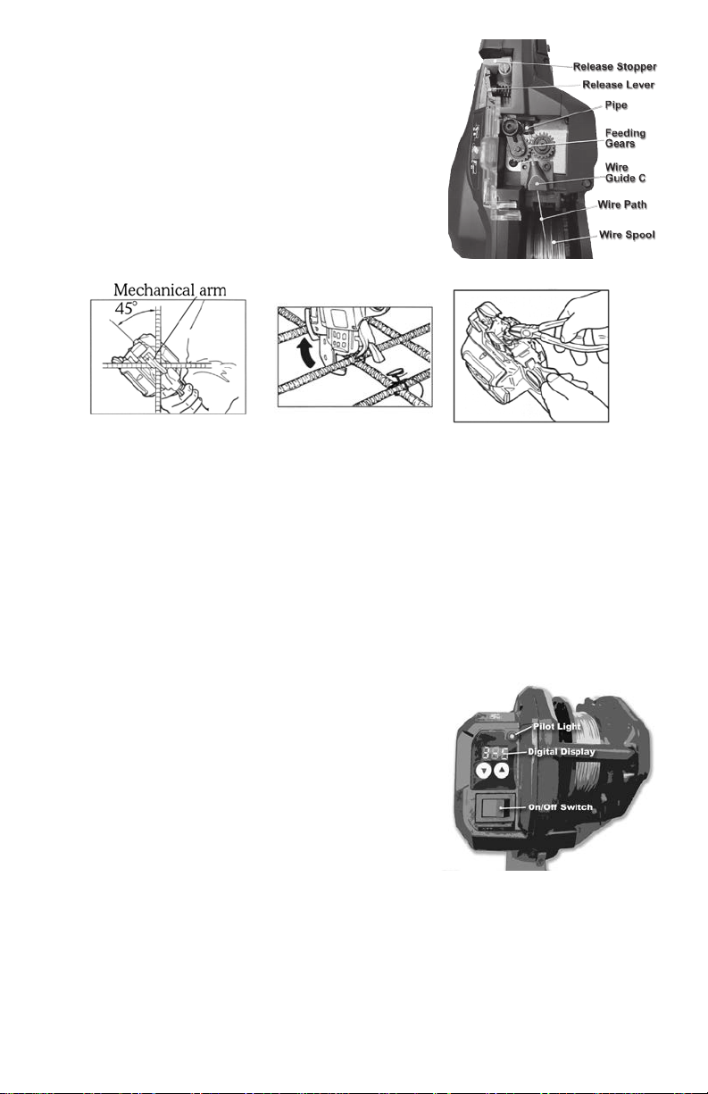
• Turn on the main power switch and unlock the
trigger. The tool is now ready for use.
How to remove the wire coil spool
• Turn o the main power switch, lock the trigger
and remove the battery.
• Press the release lever and conrm that it is
caught in the open position.
• Remove the plastic wire spool.
The Tying Procedure
• Unlock the trigger lock. Keep the mechanical arm on the rebars to be tied with a
45° angle at a vertical position to the rebars.
• Press the trigger and the tool will tie automatically.
• Remove the tool when the tying is complete.
• Do not press the trigger when the mechanical arm is not on the rebar surface.
(Note: if this should happen turn o the machine, position the trigger lock to the
“o” position and remove the trapped wire with a pair of pliers inside the machine
mouth).
• Adjust the tie tightness. There are 9 tightness levels that can be adjusted.
The Digital Display:
The left number on the LED display is the wire wraps (or
loops). The second number is the tension.
Making Wire Wrap Adjustment:
To adjust the wire wraps, hold the trigger down while
turning the tool on and it will do one less loop than the
default setting. When the tool is turned o it will reset to
the default setting. The BNT-25X and the BNT-40X default setting is three loops. The BNT-58X default setting
is four loops.
Making Tension Adjustment:
Use the up or down button to increase or decrease the tightness of the ties. 1 is the
lowest setting and 9 is the highest. Turn the tension up as much as it will tie without
breaking the twist (or pig-tail). If it breaks the pig-tail, turn down the setting until it does
not break. That is the tightest setting you can use.
Page | 6
Page 7
Replacement of Gears
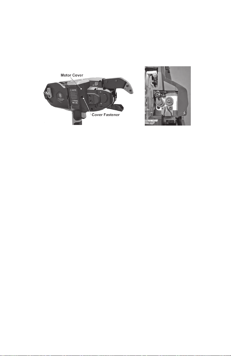
• Remove the screw that fastens the plastic cover over the motor.
• Remove Wire Guide “C” which is fastened to the plate.
• Remove the E-ring on Feed Gear B1. Press lever and remove feed gear.
• Release the lever and remove Comp. Spring 3. Be careful not to lose the smaller
Comp. Spring 4 on the Release Stopper.
• Take out the screw and washers from the Release Lever and remove the Release
Lever in the direction of the arrow.
• After you remove the Release Lever you can remove the E-ring and Pin to replace
Feed Gear B2.
• After you nish replacing the gears reassemble the tool in reverse order.
• First install the Release Lever and fasten it.
• Install Comp. Spring 4 on the Release Stopper and Comp. Spring 3 on the Release
Lever (press lever into locking position to hold springs in place while making sure
spring 4 stays in place).
• Install Feed Gear B1 and E-ring in sequence.
• Install Wire Guide C on the plate. Finally attach the Motor Cover with the screw.
Care and Maintenance
• Perform a daily inspection prior to using this tool.
• Please maintain this electric tool carefully, making sure that the adjustments are
correct and that it has been stored properly.
• Inspect the tool for damage and cracks in the housing and that the power supply is
in good working order.
• Make sure that the battery charger is the one that came with your machine. Using
another charger could cause damage to the battery and/or charger and could even
cause a re.
• Improper use of the battery could cause it to leak. If this happens it will need to be
replaced and properly recycled. Do not touch any leaking material from this battery.
If you come in contact with the battery liquid, ush with clean water and seek medical attention if necessary.
Page | 7
Page 8

If the unit is powered on with a charged battery,
contact BN Customer Service to assist in deter-
mining if repair is required.
Check to ensure that the main
switch is in the on position.
BNT-Series Tiger Tier™ Common Faults
Possible Cause Part(s) to Inspect *Recommended Action
electrode
Service is required for LED light to be functional,
if not working
Power off, then power on - deter-
mine if LED is lit or remains off
or broken wire,
(Service Required) Service is required to repair
electrode/signal wiring or repair the twisting
motor
Remove obstruction or foreign bodies; cut wire if
necessary
(Service Required) Contact Technical Service for
assistance
Fully close curl guide
Service: Electrode wire or twisting
motor has a connection or signal
failure, or damage to the twisting
motor has occurred
Check for obstruction by pulling
back the curl guide
Service: Inspect Main PWB unit,
Twister Assembly, gearbox, motor
Inspect Curl Guide. e Guide may
not be closing completely due to
bent electrode
fault
hook is obstructed
by wire
possible, requires
Service Technician
Curl guide may be
open
contamination or damage.
(Service Required) Service: Switch lever repair or
replacement may be necessary
Switch lever may be broken
Sensor failure If curl guide is closed,
*Recommended Action items that are shaded likely require professional service; Contact BN Customer Service at (800) 992-3833 for assitance
Common Fault Alert
Section Use Case or
Tone
Normal
Condition
None No power or bent
No LED light, no
operation occurs
e twister is
intialized and
the wire cutter
1 Power = On >
None LED not connected
No LED light, but
should operate
automatically
tool is fully func-
tional
4 beeps Twisting motor
Twister assembly
fails to return to its
original position
7 beeps Twister assembly
7 beeps Electronic failure
al single
Continu-
No wire is fed, or a
very short segment
pressed > Wire
2 Trigger is
beep
is released
should be fed
from the unit
beep
al single
Continu-
Page | 8
Page 9

Replace wire spool, or remove slack from the wire
spool that is causing failure for wire to feed into
the machine
(Service Required) If spool is unable to rotate or
parts appear to be damaged in the brake housing
assembly, repair may be required
Check to see if wire spool needs to
be replaced; Check spool to ensure
that wire is not loose, jammed, or
caught inside the spool
Rotate wire spool by hand, check to
ensure that the spool rotates freely.
Clean if necessary. If the spool does
Clean the wire feed (channel on Wire Guide A, or
visible obstructions) and/or remove any foreign
substances
not rotate freely; service is required.
Inspect wire feed channel for build-
up or obstruction from a foreign
object; see “How to Clear a Wire
Jam” in the BNT-X series Operator
(Service Required) Repair of wiring or feed motor
may be necessary
Ensure that bars tied are within the tying range of
the tool when in-use. If the bars to be tied do not
fit within the space alotted by the tool, a proper-
ly-sized tying machine may be necessary. Refer to
the Rebar size chart in the Operator Manual for
maximum tying capacity of the tying tool
Manual
If spool rotates freely and Wire
Guide A is clear, the feed motor
assembly may be damaged
Determine if obstruction was
caused by wire colliding with rein-
forcement bars to be tied
If Wire Guide A is dirty, it should be cleaned. If a
Wire Guide A is worn, replacement may be neces-
Inpsect wire guide A; also verify
that proper wire for the machine is
sary - contact Customer Service for assistance.
(Service Required) If Arm Unit or curl guide
are damaged, repair or replacement of parts are
necessary
being used
Inspect Arm Unit and curl guide for
damage
Possible Cause Part(s) to Inspect *Recommended Action
Common Fault Alert
Section Use Case or
Tone
Normal
Condition
3 beeps Wire spool is
empty, or wire may
be jammed inside
the spool
blocked by Reel
3 beeps Wire Spool is
No wire is fed, or a
very short segment
pressed > Wire
2 Trigger is
Press or there is
is released
should be fed
damage to the
brake assembly
from the unit
Wire Feed
(check Guide A)
is blocked by a
foreign object or
buildup of dirt
Feed motor or
Page | 9
wiring to the feed
motor is damaged
structed by contact
with rebar during
tying
None Wire tie is ob-
Loop is inconsistent
and/or is deflected
from the curl guide
should form a
circular pattern
(loop) and
should com-
plete a twist-tie
3 Binding Wire
around bar(s)
Loop is oversized /
too large
Curl guide or Arm
Unit is damaged
or bent
Page 10

Clean and/or remove buildup or foreign sub-
stances from brake housing assembly, lubricate
Inspect brake housing for dirt and
foreign substances
as needed
Replace spool with BNT-40-WIRE compatible
wire spool
Determine if tie-wire is designed to
work with the BNT-25X/40X/58X
tying machines
(Service Required) Brake motor assembly may be
damaged or require repair or replacement
If brake housing is clean and free
of substances, and wire spool is
compatible with machine, contact a
service representative
Clear wire jam or obstruction
Check for wire jam or obstruction;
see “How to Clear a Wire Jam” in
Refer to the Operator Manual to check rebar (size)
tying range; use adjustment dial (on some models)
or digital display to adjust tightness of rebar ties
(tie needs to be tighter). In some instances the
loop size may be incorrect, and may require Ser-
vice (contact Customer Service for assistance)
the BNT-X series Operator Manual
Check to ensure that rebar being
tied fits within the tying range of the
tool; then check tighness setting on
the tying machine
Possible Cause Part(s) to Inspect *Recommended Action
Common Fault Alert
Section Use Case or
Tone
Normal
Condition
blocked by buildup
or blocked by for-
None Brake assembly is
Wire is loose on the
spool
wire spool
should
4 Wire feeds,
eign substance
dispense wire
consistently
with no excess
(slack) in wire
third-party prod-
uct not designed
for use with tool
None Wire spool is a
Wire is loose on the
spool
coil
wire spool
should
dispense wire
consistently
with no excess
(slack) in wire
4 Wire feeds,
brake assembly
motor
None Damage to the
coil
too small
None Loop diameter is
Wire loop is fed,
but machine fails to
twist-tie should
5 Wire is fed and
twist wire
be formed
snugly around
the bar(s)
None Tightness adjust-
Tie is loose or
ment is too low; or
broken
it is possible that
Rebar tied is not
within the tying di-
ameter range (too
large or too small)
for the tool
Page | 10
Page 11

• When not in use, store this tool carefully in the supplied case. It can be
washed with a soft cloth and soapsuds after you nish work. Do not use
petroleum chemicals or alcohol to clean this tool.
• In the event that this tool malfunctions or drops in performance you can
contact our Customer Service Repair Center:
(800) 992-3833 or [email protected].
#1 #2 #3 #4 #5
BNT-25X
Mesh x x x x x x
#1 1/8” 6mm x x x x x x
#2 1/4” 8mm x x x x x
#3 3/8” 10mm x x x x x
#4 1/2” 13mm x x x x
#5 5/8” 16mm x x
BNT-40X
#1 1/8” 6mm x x x x x x x x
#2 1/4” 8mm x x x x x x x x x
#3 3/8” 10mm x x x x x x x x x
#4 1/2” 13mm x x x x
#5 5/8” 16mm x x x x x x x
#6 3/4” 20mm x x x x x x
#7 7/8” 22mm x x x x x
#8 1” 25mm x x x x
#9 1-1/8” 29mm x x x
#10 1-1/4” 32mm x x
1/8” 1/4” 3/8” 1/2” 5/8”
Mesh
6mm 8mm 10mm 13mm 16mm
#1 #2 #3 #4 #5 #6 #7 #8 #9 #10
1/8” 1/4” 3/8” 1/2” 5/8” 3/4” 7/8” 1” 1-1/8” 1-1/4”
6mm 8mm 10mm 13mm 16mm 20mm 22mm 25mm 29mm 32mm
x x x x
#3 #4 #5 #6 #7 #8 #9 #10 #11 #14
BNT-58X
#1 1/8” 6mm x x x x x
#2 1/4” 8mm x x x x x x
#3 3/8” 10mm x x x x x x x
#4 1/2” 13mm x x x x x x x x
#5 5/8” 16mm x x x x x x x x
#6 3/4” 20mm x x
#7 7/8” 22mm x x x x x x x
#8 1” 25mm x x x x x x
#9 1-1/8” 29mm x x x x x
#10 1-1/4” 32mm x x x x
#11 1-3/8” 36mm x x x
#14 1-3/4” 43mm x x
3/8” 1/2” 5/8” 3/4” 7/8” 1” 1-1/8” 1-1/4” 1-3/8” 1-3/4”
10mm 13mm 16mm 20mm 22mm 25mm 29mm 32mm 36mm 43mm
x x x x x x
Page | 11
Page 12
How To Clear A Wire Jam On
The BNT X Series Rebar Tiers
The three-beep audio error code on the BNT X Series Rebar Tier most likely signies a
wire jam in the nose of the tool. Here are the steps you can take to clear misfed wire.
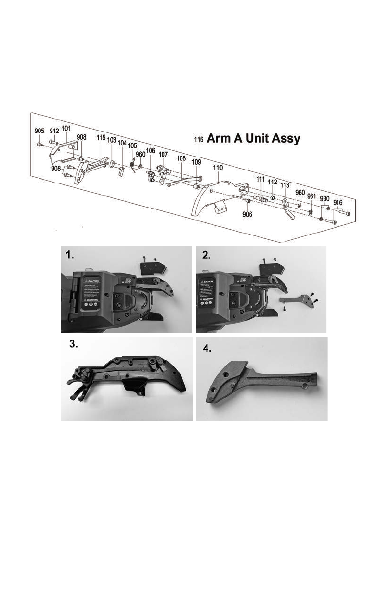
1. Remove the two hex fasteners (905 & 912). A 2.5mm tool is supplied with the tier.
Remove the arm unit cover plate (101) and set it aside (see picture 1).
2. Remove the three (3) hex fasteners (908) on the wire guide (115) and remove it
(picture 2).
leave the wire cutters and the connecting rod (108) in place (see picture 3)
3. Clean the channel on the backside of the wire guide with a wire brush or small screwdriver (see picture 4)
Page | 12
Page 13
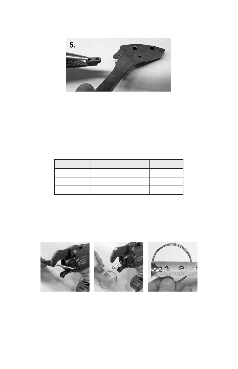
4. Reassemble the tool in reverse order. Make sure that the notch on the connecting
plate ts into the half moon cutout on the wire guide as seen in Picture 5. **Note: A tiny
bit of grease can be put on the linkage points and xed cutter but not too much as this
will attract debris.
Note: Do not over tighten any of the fasteners.
Loop Diameters and Wire Lengths
Tiger T ier Diameter Length
BNT-25X 1-13/16 to 1-15/16 in. 24-3/4 in.
BNT-40X 2-1/4 to 2 3/8 in. 31 in.
BNT-58X 3 to 3-1/8 in. 48 in.
Getting a loop sample
1. Pull the trigger while holding a screwdriver or pen in the tying position
2. Push the loops forward after pulling the trigger but before the tool twists the loops.
3. You can now measure the diameter of the loops.
The BNT-Series are hand-held battery operated tools. The tool is designed to be used
for the fast tying of rebar or steel used in construction sites for the building trades. Due
to its speed, convenience and safety, this machine can save a great deal of valuable
labor and material resources. In addition, the parts and components as well as advanced production technologies are made from well-known manufacturers both here
and abroad. This machine was developed as an economical and practical tying machine
with many international patents.
Page | 13
Page 14

For additional information including:
• Product Parts List
• Product Literature
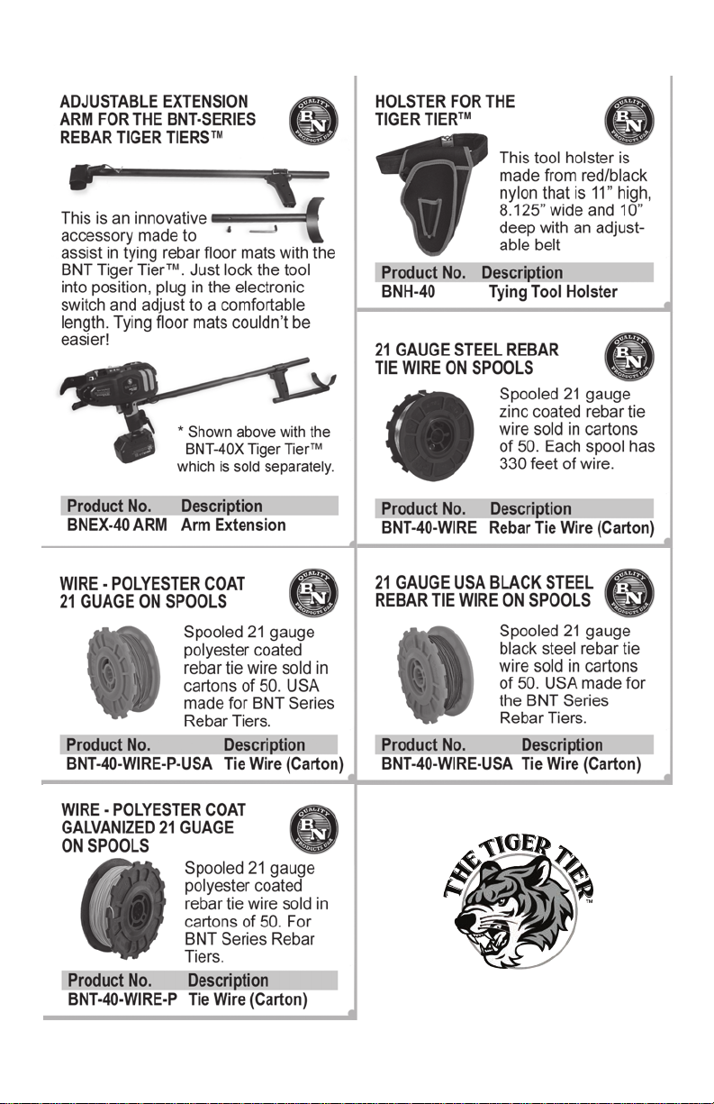
• BNT Wire Supplies
• BNEX-40X - Arm extension with electronic trigger
• BNH-40 Holster - Heavy-duty holster
• BNTLI-20 - Replacement Lithium-ion Battery (18V)
• BNTLI-20C - Replacement Charger for the BNTLI-20 Battery
Visit www.bnproducts.com or call (800) 992-3833
NOTES:
____________________________________________________
____________________________________________________
____________________________________________________
____________________________________________________
____________________________________________________
____________________________________________________
____________________________________________________
____________________________________________________
____________________________________________________
____________________________________________________
____________________________________________________
____________________________________________________
____________________________________________________
____________________________________________________
Page | 14
Page 15
BNT Series Accessories & Supplies
Page | 15
Page 16

 Loading...