

Page 1
1-1
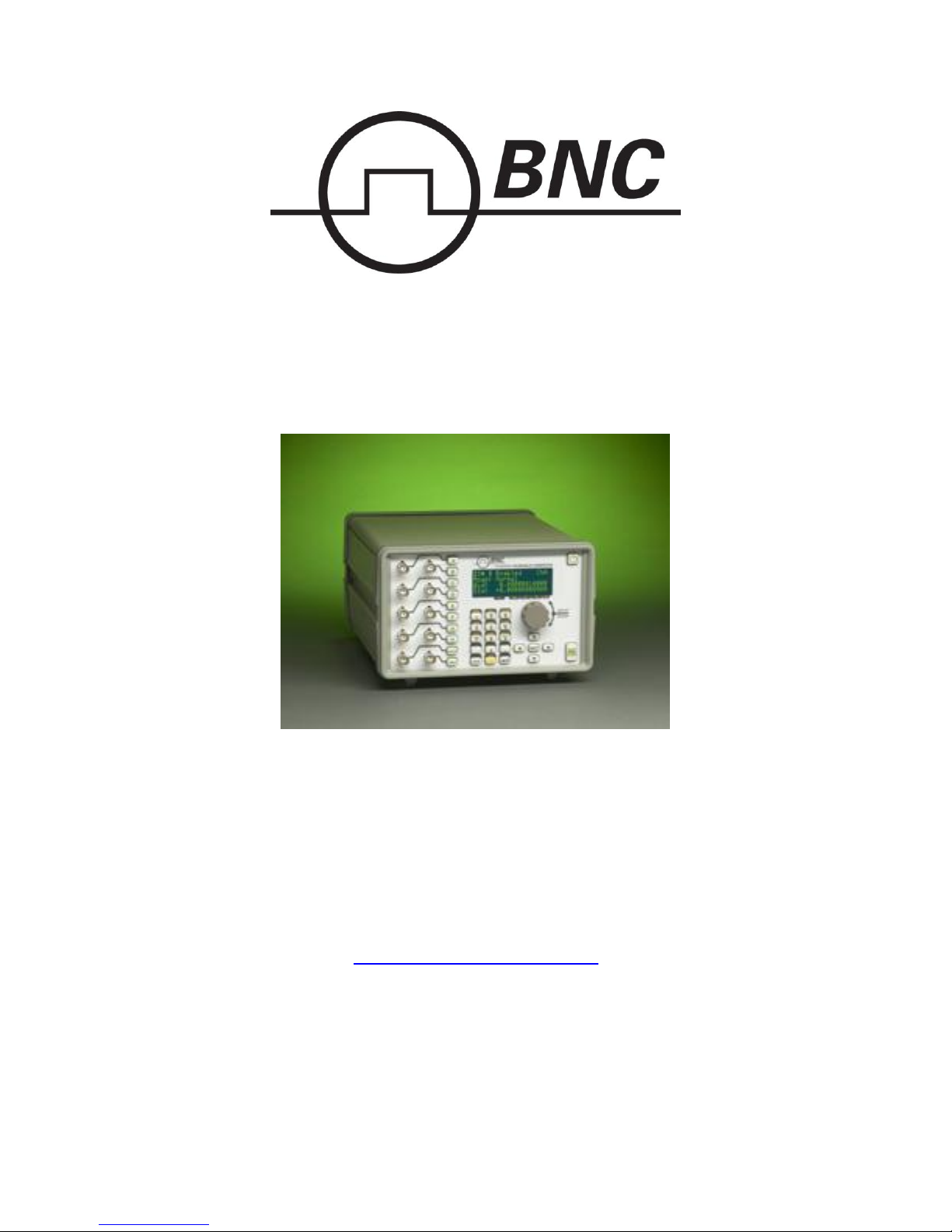
575 Series Pulse Generator
Operating Manual
Version 5.6
Berkeley Nucleonics Corp.
2955 Kerner Blvd.
San Rafael, CA 94901
(415) 453-9955 phone
(415) 453-9956 fax
www.berkeleynucleonics.com
Page 2

1-2
1 Table of Contents
1 Table of Contents ....................................................................................... 1-2
2 Introduction ................................................................................................. 2-6
Technical Support ........................................................................................................ 2-6
Warranty ...................................................................................................................... 2-6
Package Contents ......................................................................................................... 2-6
3 Safety Issues .............................................................................................. 3-7
4 Front Panel Overview ................................................................................. 4-8
575 Front Panel ............................................................................................................ 4-8
Display Layout and Indicators ................................................................................. 4-8
Description of Front-Panel Area .............................................................................. 4-8
5 Pulse Concepts and Pulse Generator Operations .................................... 5-10
Counter Architecture Overview ................................................................................. 5-10
System Timer Functions ............................................................................................ 5-10
Channel Timer Functions ........................................................................................... 5-11
Digital Output Multiplexer ........................................................................................ 5-11
Dependent & Independent Timing Events ................................................................. 5-11
Navigating the 575 Front Panel ................................................................................. 5-12
Selecting Menus ..................................................................................................... 5-12
Selecting Menu Items ............................................................................................ 5-12
Numeric Input Mode .............................................................................................. 5-12
Entering Non-Numeric Parameters ........................................................................ 5-12
Alphanumeric Input Mode ..................................................................................... 5-13
Enabling System Output ........................................................................................ 5-13
Enable/Disable Channel Output ............................................................................. 5-13
Rearming the Channel Timers ............................................................................... 5-13
Setting Pulse Timing Parameters ........................................................................... 5-14
Setting Pulse Output Parameters ............................................................................ 5-14
Using the Output Multiplexer ................................................................................ 5-14
Setting System Internal Rate Parameters ............................................................... 5-14
6 575 Menu Structure .................................................................................. 6-16
System Mode Menus (FUNC + MODE key) ............................................................ 6-16
Setting System Mode of Operation ........................................................................ 6-16
Channel Menus (A, B, C, D, E, F, G, or H key) ........................................................ 6-16
Timing Menu ......................................................................................................... 6-16
Output Configuration Menu ................................................................................... 6-16
Mode Menu ............................................................................................................ 6-17
Wait Menu ............................................................................................................. 6-17
Enabling Channel Output ....................................................................................... 6-17
Setting the Channel Timing Parameters ................................................................ 6-17
Setting Pulse Configuration Output Type .............................................................. 6-17
Setting Channel Mode of Operation ...................................................................... 6-17
Delaying the Start of Channel Output .................................................................... 6-18
Advanced Channel Menus (FUNC + A, B, C, D, E, F, G or H key) ......................... 6-18
Multiplexer Menu .................................................................................................. 6-18
Page 3

1-3
Configuring the Channel Multiplexer .................................................................... 6-18
Channel Gate Menu ............................................................................................... 6-18
Setting the Sync Source ......................................................................................... 6-18
Setting Channel Gate Control ................................................................................ 6-18
Clocks/Rate Menus (FUNC + RATE key) ................................................................ 6-19
Internal Reference Menu........................................................................................ 6-19
Setting the Internal Reference Source and Rate .................................................... 6-19
Reference Out Menu .............................................................................................. 6-20
Setting the Output Reference ................................................................................. 6-20
Trigger Menus (TRIG key) ........................................................................................ 6-20
Enabling System Trigger ....................................................................................... 6-20
Gate Menus (GATE key) ........................................................................................... 6-20
Standard Gate Menu .............................................................................................. 6-20
Enabling System Gate ............................................................................................ 6-21
System Configuration Menus (FUNC + SYSTEM key) ........................................... 6-21
Communication Interface Menu ............................................................................ 6-21
Setting System Communication Parameters .......................................................... 6-21
User Options Menu 1 ............................................................................................. 6-21
Setting Keypad Parameters .................................................................................... 6-21
User Options Menu 2 ............................................................................................. 6-22
Setting the Auto Start Mode .................................................................................. 6-22
Setting the Display Decimal Mark ......................................................................... 6-22
Setting the Display Brightness ............................................................................... 6-22
Store Menu (FUNC + STORE key) ........................................................................... 6-22
Storing a Configuration.......................................................................................... 6-22
Recall Menu (FUNC + RECALL key) ...................................................................... 6-23
Recalling System Configurations .......................................................................... 6-23
Counter Menu (FUNC + AUX1 key) ........................................................................ 6-23
Using the Counter Function ................................................................................... 6-23
Information Menus (FUNC + 0 key) ......................................................................... 6-23
Information Menu A .............................................................................................. 6-23
Information Menu B .............................................................................................. 6-23
7 Operating the 575 ..................................................................................... 7-24
Quick Start - Normal Internal Rate Generator Operation .......................................... 7-24
Quick Start - Normal External Trigger Operation ..................................................... 7-24
System Timer Overview ............................................................................................ 7-25
To Use Continuous Mode ...................................................................................... 7-25
To Use Single Shot Mode ...................................................................................... 7-25
To Use System Burst Mode Function .................................................................... 7-25
To Use System Duty Cycle Function..................................................................... 7-26
Channel Timer Overview ........................................................................................... 7-26
To Use Channel Normal Mode Function ............................................................... 7-26
To Use Channel Single Shot Function ................................................................... 7-27
To Use Channel Burst Mode Function .................................................................. 7-27
To Use the Channel Duty Cycle Function ............................................................. 7-27
To Use the Channel Gating Function..................................................................... 7-28
Page 4

1-4
External Input Overview ............................................................................................ 7-28
To Generate a Pulse on Every Trigger Input ......................................................... 7-28
To Generate a Burst of Pulses on Every Trigger Input .......................................... 7-29
To Start a Continuous Stream of Pulses Using the External Trigger .................... 7-29
To use the External Gate to Control the System .................................................... 7-30
8 Programming the 575 ............................................................................... 8-31
Personal Computer to Pulse Generator Communication ........................................... 8-31
RS232 Interface Overview ......................................................................................... 8-31
USB Interface Overview ............................................................................................ 8-32
GPIB Interface Overview .......................................................................................... 8-32
Ethernet Interface Overview ...................................................................................... 8-32
Programming Command Types and Format .............................................................. 8-33
Line Termination ....................................................................................................... 8-33
IEEE 488.2 Common Command Format ................................................................... 8-33
SCPI Command Format ............................................................................................. 8-34
SCPI Command Keywords .................................................................................... 8-34
SCPI Command Format ......................................................................................... 8-34
SCPI Keyword Separator ....................................................................................... 8-34
SCPI Optional Keywords ....................................................................................... 8-35
SCPI Specific and Implied Channel ...................................................................... 8-35
SCPI Parameter Types ........................................................................................... 8-35
Error Codes ............................................................................................................ 8-35
Programming Examples ......................................................................................... 8-36
575 INSTrument Commands (SCPI Command Summary) ................................... 8-37
575 System PULSe[0] Commands (SCPI Command Summary) .......................... 8-38
575 Channel PULSe[n] Commands (SCPI Command Summary) ........................ 8-39
575 SYSTem Commands (SCPI Command Summary) ........................................ 8-40
575 DISPlay Commands (SCPI Command Summary) ......................................... 8-41
IEEE 488.2 Common Commands .......................................................................... 8-41
INTERNAL RATE GENERATOR ............................................................................ A-1
PROGRAMMABLE TIMING GENERATOR .......................................................... A-1
SYSTEM EXTERNAL TRIGGER/GATE INPUT(S) ............................................... A-1
MODULE SPECIFICATIONS ................................................................................... A-2
TTL/ADJUSTABLE DUAL CHANNEL OUTPUT MODULE (Standard) .............. A-2
TRIGGER INPUT .................................................................................................. A-3
GATE INPUT ......................................................................................................... A-3
OPTICAL OUTPUTS ................................................................................................. A-3
OPTICAL INPUTS ..................................................................................................... A-3
EXTERNAL CLOCK IN/OUT .................................................................................. A-3
GENERAL .................................................................................................................. A-3
OUTPUT MODULES ................................................................................................ A-4
Standard .................................................................................................................. A-4
Optional................................................................................................................... A-4
INPUT MODULES .................................................................................................... A-4
Standard .................................................................................................................. A-4
Optional................................................................................................................... A-4
Page 5

1-5
System Options ....................................................................................................... A-4
Safety Marking Symbols............................................................................................. B-5
COM Overview ........................................................................................................... C-8
GPIB Interface ............................................................................................................ C-8
Ethernet Interface ........................................................................................................ C-8
IP Address and Raw TCP/IP Connection ............................................................... C-8
Determining IP Address .......................................................................................... C-8
DT15 Overview ........................................................................................................ D-10
DT15 Menus ............................................................................................................. D-10
Trigger 1 Menu (TRIG key) ................................................................................. D-10
Enabling System Trigger ...................................................................................... D-10
Trigger 2 Menu (GATE key) * ............................................................................. D-10
DT15 SCPI Command Summary.............................................................................. D-11
DT15 IEEE 488.2 Command Summary ................................................................... D-11
AT35 Description....................................................................................................... E-12
AT35 Specifications................................................................................................... E-12
TZ50 Overview .......................................................................................................... F-13
TZ50 Specifications ................................................................................................... F-13
TTL/CMOS Mode ................................................................................................. F-13
Adjustable Mode .................................................................................................... F-13
Increment Overview.................................................................................................. G-14
Increment Menus ...................................................................................................... G-14
System Mode Menu 1 Extensions (FUNC + MODE key) ................................... G-14
System Mode Menu 2 Extensions (FUNC + MODE key) ................................... G-14
Setting System Increment Modes of Operation .................................................... G-14
Advanced Channel Menu Increment Extension (FUNC + channel key) .............. G-15
Setting the Channel Increment Parameters ........................................................... G-15
Increment SCPI Command Summary ....................................................................... G-15
Increment Initialization and Reset (FUNC + CLR) .................................................. G-15
Increment Specifications ........................................................................................... G-15
AT45 Option Overview ............................................................................................ H-17
AT45 Protection Error Messages .............................................................................. H-17
Module Errors ....................................................................................................... H-17
System Limit Error ............................................................................................... H-17
Voltage Change Timing ........................................................................................ H-17
AT45 Channel Menus ............................................................................................... H-17
Channel Output Configuration Menu ................................................................... H-17
AT45 SCPI Command Extension Summary............................................................. H-18
AT45 Specifications.................................................................................................. H-18
Page 6

2-6
2 Introduction
This manual is a reference designed to familiarize you with the Berkeley
Nucleonics 575 series pulse generator and is arranged so that you can easily
find the information you’re looking for. Generally, each topic has its own section
and no section assumes that you’ve read anything else in the manual.
Technical Support
For questions or comments about operating the 575 -- our technical staff can be
reached via one of the following methods:
Phone: (415) 453-9955
Fax: (415) 453-9956
Online: www.berkeleynucleonics.com
Warranty
In addition to a 30-day money back guarantee, the 575 has a two-year limited
warranty from the date of delivery. This warranty covers defects in materials and
workmanship. Berkeley Nucleonics will repair or replace any defective unit.
Contact us for information on obtaining warranty service.
Package Contents
The box you receive should contain the following:
575 Pulse Generator
AC Power Cord
Disc that includes
o Operating Manual
o Software Drivers
o Communication Software
Contact Berkeley Nucleonics (415) 453-9955 if any parts are missing.
Page 7

3-7
3 Safety Issues
Normal use of test equipment presents a certain amount of danger from electrical
shock because testing must be performed where exposed voltage is present. An
electrical shock causing 10 milliamps of current to pass through the heart will
stop most human heartbeats. Voltage as low as 35 V (DC or RMS AC) should
be considered dangerous and hazardous since it can produce a lethal current
under certain conditions. Higher voltages pose an even greater threat because
such voltage can easily produce a lethal current. Your normal work habits should
include all accepted practices that will prevent contact with exposed high
volt-age, and steer current away from your heart in case of accidental contact
with a high voltage. You will significantly reduce the risk factor if you know and
observe the following safety precautions:
If possible, familiarize yourself with the equipment being tested and the
location of its high-voltage points. However, remember that high voltage
may appear at unexpected points in defective equipment.
Do not expose high voltage needlessly. Remove housing and covers only
when necessary. Turn off equipment while making test connections in
high-voltage circuits. Discharge high-voltage capacitors after shutting
down power.
When testing AC powered equipment, remember that AC line voltage is
usually present on power input circuits, such as the on-off switch, fuses,
power transformer, etc.
Use an insulated floor material or a large, insulated floor mat to stand on,
and an insulated work surface on which to place equipment. Make certain
such surfaces are not damp or wet.
Use the time-proven “one hand in the pocket” technique while handling an
instrument probe. Be particularly careful to avoid contact with metal
objects that could provide a good ground return path.
Never work alone. Someone should always be nearby to render aid if
necessary. Training in CPR first aid is highly recommended.
Page 8

4-8
4 Front Panel Overview
575 Front Panel
Display Layout and Indicators
A 4 line x 20 character vacuum fluorescent display module displays parameters
and status information. The status information is located in the upper-left corner
of the display, between the two brackets. There are four enunciators:
↕ A vertical arrow indicates there are additional pages
to the current menu.
☼ An alternating hollow and then solid circle indicates
the unit is actively generating pulses, or armed and
waiting for an external trigger.
♪ A musical note indicates the function key has been
pressed.
? In external oscillator operation, a question mark
indicates the internal pll is not yet locked with the
external clock signal.
The upper-right side of the display contains the title of the currently displayed
menu. The rest of the display is used for system parameters. The display
brightness may be adjusted, allowing the instrument to be used under various
lighting conditions.
Description of Front-Panel Area
Keypads
Three keypad areas provide fast access to various menus and easy editing of
system parameters.
Channel Keypad Provides one touch access to the menus for setting
Arrow Keypad The up (UP) and down (DOWN) arrow keys are used
up the channel parameters. Pressing the appropriate
letter will display the parameters for the
corresponding channel. Example: Pressing the A key
will access the Channel A menus.
to increment/decrement the current parameter
(indicated by the blinking cursor). The position of the
cursor controls the step size for each increment. The
Page 9

4-9
right (RIGHT) and left (LEFT) arrow keys moves the
cursor to different positions within the current
parameter. The NEXT key selects the next parameter
in the currently displayed menu.
Numeric Keypad Allows numbers and alphanumeric values to be
en-tered. When entering alphanumeric values,
pressing a key will display the first letter shown on the
key. The yellow FUNC key allows the keys to select
the yellow functions.
Repeated key presses will toggle through all the letters, both upper and lower
case, shown on the keycap. To enter two letters which appear on the same
keycap, se-lect the first character, then use the right arrow to shift to the next
position and enter the next letter. When data entry is complete the ENTER key
must be pressed.
Rotary Adjustment Knob
As an alternative to the Arrow Keypad, the Rotary Adjustment Knob may be used
to adjust the current parameter. The step size is controlled by the position of the
cursor; however turning the knob faster will increase the step size. Pushing the
knob will perform functions similar to the NEXT key and switch to the next
parameter in the currently displayed menu.
Second Level Menus (Function Key)
The second level menus (indicated in yellow above certain keys) are accessed
through the use of the yellow function (FUNC) key. Pressing the FUNC key once
and then pressing the desired menu key will display the specified second level
menu. Pressing the FUNC key twice in succession will put the unit into “Function
Lock” mode, where the second level menus can be accessed without repeatedly
pressing the FUNC key. Pressing the FUNC key a third time will exit “Function
Lock” mode.
Page 10
5-10
5 Pulse Concepts and Pulse Generator
Operations
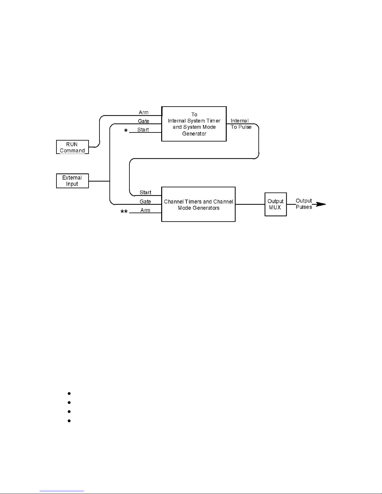
Counter Architecture Overview
*Start source is: RUN/STOP key in Internal Modes
External input in External Trigger modes
*TRG command via Serial/GPIB access
**Channels are armed by the RUN button. In single shot and burst modes
channels may be rearmed by pressing the RUN button.
System Timer Functions
The System Timer functions as a non-retriggerable, multi-vibrator pulse
generator. This means that once started, depending on the mode, the timer will
pro-duce pulses continuously. Before pulses can be generated, the timer must
be armed and then receive a start pulse. Arming the counter is done by pressing
the RUN/STOP key. With external trigger disabled, the RUN/STOP key also
generates the start command for the counter. With external trigger enabled, the
external trigger provides the start pulse. In either case, once started, the counter
operation is determined by the System Mode Generator. Standard modes
include:
Continuous Once started T0 pulses are generated continuously.
Single Shot One T0 pulse is generated for each start command.
Burst ‘n’ T0 pulses are generated for each start command.
Duty Cycle Once started T0 pulses cycle on and off continuously.
Page 11

5-11
The T0 pulses are distributed to all of the start inputs of the Channel Timers and
Mode Generators
Channel Timer Functions
The Channel Timer functions as a non-retriggerable, delayed, one shot pulse
generator. This means that the timer will only generate one delayed pulse for
every start pulse received. Once the channel timer has started counting,
addi-tional start pulses will be ignored until the pulse has been completed
(non-retriggerable). The start pulse for each channel is provided by the internal
T0 pulse generated by the Internal System Timer. Whether or not a pulse is
gener-ated for each T0 pulse is determined by the Channel Mode Generator.
Standard modes include:
Normal A pulse is generated for each T0 pulse.
Single Shot One pulse is generated at the first T0 pulse, after
which output is inhibited.
Burst A pulse is generated for each T0 pulse, 'n' times, after
which output is inhibited.
Duty Cycle ‘n’ pulses are generated for each T0 pulse after which
the output is inhibited for ‘m’ times. The cycle is then
repeated.
Different modes may be selected for each output, allowing a wide variety of
output combinations. Each output may also be independently disabled or gated
(using the external gate input).
Digital Output Multiplexer
The outputs of the Channel Timers are routed to a set of multiplexers. This
allows routing of any or all Channel Timers to any or all of the unit outputs. In the
normal mode of operation, the output of the Tn Channel Timer is routed to the Tn
output connector. As an example, if a double pulse is required on Channel A
output, one can multiplex the Channel A timer with the Channel B timer adjusting
each timer to provide the necessary pulses.
Dependent & Independent Timing Events
The 575 allows the user to control the relationship between the Channel Timers
by setting the sync source for each timer. Independent events are all timed
relative to the internal T0 start pulse. Dependent events may be linked together
by setting the sync source to the controlling event. This allows the instrument to
match the timed events and adjustments can be made in one event without
detuning the timing between it and a dependent event.
Page 12

5-12
Navigating the 575 Front Panel
Selecting Menus
Parameters are grouped in menus, selectable using menu keys. To select the
output channel parameters press the letter key corresponding to the desired
channel. To select second level menus press the FUNC key and then the key
corresponding to the desired function. To select advanced channel menus press
the FUNC key followed by the desired channel key. Menus may include a
number of different pages with each page containing up to four parameters. The
status block in the upper-left corner of the display shows a vertical arrow if the
current menu contains additional pages. To select the next page, press the
channel button again or select the same second level menu by pressing the
FUNC key and the channel/menu key again.
Selecting Menu Items
Within a menu, the blinking cursor indicates the current menu item for editing.
The NEXT key or pressing the adjustment knob will select a different menu item.
Numeric Input Mode
When the current item is numeric, the system enters the Numeric Input Mode. In
this mode data may be edited in one of three ways. Using the arrow keypad, the
left (LEFT) and right (RIGHT) arrow keys are used to select a digit to edit. The
selected digit blinks to identify itself as the active digit. The UP and DOWN arrow
keys are then used to increment or decrement this digit. Alternately, after using
the LEFT and RIGHT arrow keys to select an active digit, the adjustment knob
may be used to increment and decrement this digit. The adjustment knob
features speed de-pendent resolution. Slow rotation will increment or decrement
the active digit by one. As you increase the speed of rotation, the parameter will
be 10 to 1000 times faster depending on the speed.
An additional entry mode is using the numeric keypad. Enter the number,
including decimal point using the numeric keypad. Complete the number using
the ENTER key. To clear number entry and/or start over press the clear key
(CLR). Pressing the CLR key a second time will exit the numeric keypad mode
and restore the original number.
The last entry mode is a modified form of scientific notation. The FUNC button
acts as 10- in this case. Type in the value followed by FUNC then the number
button that represents the power desired. For example 64us is entered as 6, 4,
FUNC, and then 6.
Entering Non-Numeric Parameters
When the current item is non-numeric, the UP and DOWN arrow keys are used
to select among different options for the parameter. The adjustment knob may
also be used to change the selection. If the item is an on-off toggle, the UP arrow
Page 13

5-13
(CW adjustment knob) enables the item and the DOWN arrow (CCW adjustment
knob) disables the item.
Alphanumeric Input Mode
When the current item is alphanumeric, the system enters the Alphanumeric
Input Mode. In this mode, data is entered using the alphanumeric keypad.
Pressing a key will display the first letter shown on the keypad. Repeated key
presses will toggle through all the letters, both upper and lower case, shown on
the key cap. To enter two letters which appear on the same key cap, select the
first character, then use the right arrow to shift to the next position and enter the
next letter. The Left and Right arrow keys may be used to position the cursor to
edit any character. When data entry is complete, the ENTER key must be
pressed. The keys contain the following characters:
1 1 2 3 4 5 6 7 8 9 0
2 A B C a b c 2
3 D E F d e f 3
4 G H I g h i 4
5 J K L j k l 5
6 M N O m n o 6
7 P Q R S p q r s 7
8 T U V t u v 8
9 W X Y Z w x y z 9
0 0 1 2 3 4 5 6 7 8 9
. . , # $ % & ? • -- + * / space
Enabling System Output
The RUN/STOP key is used to arm the system. With external trigger disabled,
the key will arm and start pulse output. With external trigger enabled, the key will
arm the pulse generator. Pulse output then starts after the first valid trigger input.
Pressing the RUN/STOP key a second time disables the pulse generator.
Enable/Disable Channel Output
At the top of each channel menu page is a parameter to enable or disable the
output of the channel. Each channel may be individually enabled or disabled. An
illuminated channel key indicates that the channel is enabled.
Rearming the Channel Timers
In the channel single shot mode and burst mode, the Channel Timers may be
rearmed after completing the initial output by pressing the FUNC key followed by
the RUN/STOP key. If there are channels currently running in normal mode,
single shot and burst channels can be re-armed without affecting the timing on
normal mode channels by pressing function RUN/STOP.
Page 14

5-14
Setting Pulse Timing Parameters
Pulses are defined by a delay, from their sync or start pulse to the active edge,
and a width.
Wid: Sets the width of the active portion of the pulse.
Dly: Sets the delay from the sync source to the start of the pulse.
NOTE: If Wid + Dly + 75 ns (hardware reset time) > T0 Period, the correct pulse
width will be generated but at a slower rate.
Setting Pulse Output Parameters
There are three basic types of outputs available on the 575: (a) TTL/CMOS
compatible outputs; (b) adjustable amplitude outputs; (c) optical outputs.
Out: Selects between TTL/CMOS mode and Adjustable mode
when both are available on a single output.
Pol: Sets the voltage polarity of the pulse, active high or active
low. Note: All outputs are positive - negative voltages are
not supported.
Ampl: In adjustable mode, it sets the unloaded output voltage. The
actual output voltage will depend on the load impedance. For
example: If the load is 50 ohms, the output will be 50% of the
stated voltage.
Using the Output Multiplexer
Each output channel includes a multiplexer which allows routing any or all of the
timer outputs to the physical output. This allows double pulses and other
com-plex pulse trains to be generated. Only timing parameters are multiplexed
together, not amplitudes.
-HGFEDCBA-
Mux: -00000101-
The multiplexer is represented by an “n” bit binary number as shown above. “n” is
the number of channels. Each bit represents a channel timer, which is enabled
by setting the bit to one. In the above example, timers A and C are combined on
the current output.
Setting System Internal Rate Parameters
The internal T0 period controls the fundamental output frequency of the system.
Each channel may operate at submultiples of the fundamental frequency using
their duty cycle mode.
Source: Sets the reference source for the internal T Period.
Per: Sets the internal T Period.
Page 15

5-15
To set the system Internal Rate - press the yellow FUNC key, then press the
RATE key, and then use the dial or number pad to specify the T0 Period.
Page 16
6-16
6 575 Menu Structure
MODE:
Continuous
MODE: Single
Shot
MODE: Burst
MODE: Duty
Cycle
#/On
#/Burst
#/Off
Channel Enable
Sync Source
Pulse Width
Delay
Channel Enable
Channel Enable
Channel Enable
Channel Enable
Channel Enable
Output Type:
TTL/CMOS
Output Type:
Adjustable
Output Type:
Optical
Output Type:
High Z
Output Type:
Low Z
Polarity
Polarity
Polarity
Polarity
Output Level
Output Level
Output Level
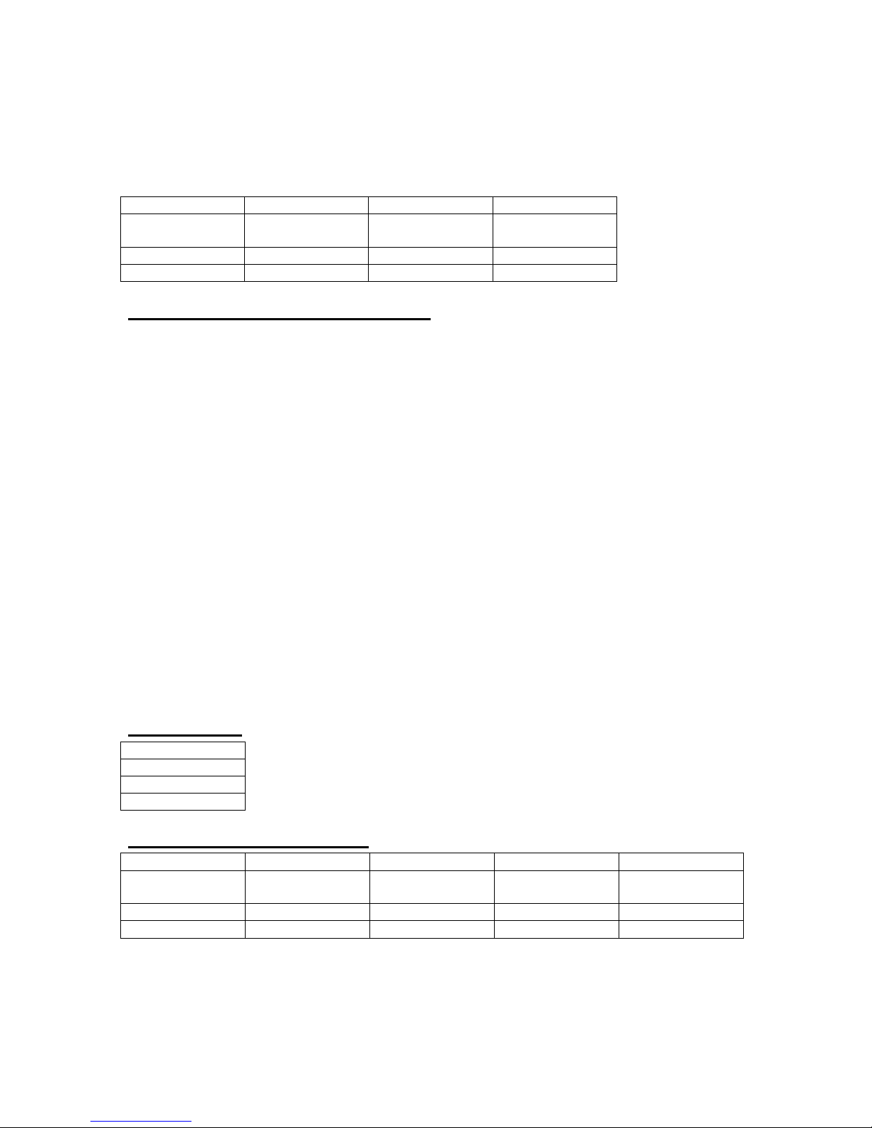
System Mode Menus (FUNC + MODE key)
Setting System Mode of Operation
The MODE menu sets the T0 system timer mode. The menu will show the extra
set parameters (Burst, On & Off) only when they are appropriate.
Mode: Selects the T0 mode: Continuous, Single Shot, Burst or Duty
Cycle mode.
Burst: Sets the number of pulses to be generated when in Burst
mode.
On: Sets the number of pulses to be generated during each on
cycle.
Off: Sets the number of pulses to skip each during off cycle when
in the Duty Cycle mode.
*NOTE: Any mode may be started by either the RUN/STOP key in the internal
trigger mode or armed by the RUN/STOP key and started by an external trigger
in the external trigger mode. In the single shot and burst modes, (internally
triggered) the unit disarms itself at the end of the pulse train. Pressing the
RUN/STOP key after the unit has been disarmed will generate a new pulse train.
Channel Menus (A, B, C, D, E, F, G, or H key)
Timing Menu
Output Configuration Menu
Page 17
6-17
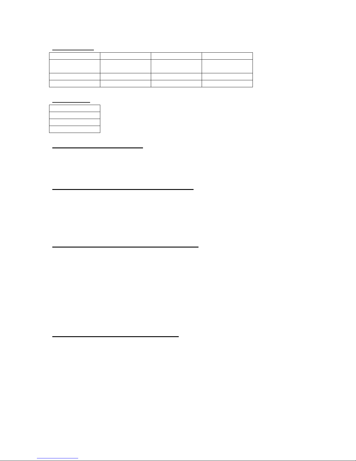
Mode Menu
Channel Enable
Channel Enable
Channel Enable
Channel Enable
Mode: Normal
Mode: Single
Shot
Mode: Burst
Mode:
Duty Cycle
#/On Pulses
#/Burst Pulses
#/Off Pulses
Channel Enable
#/Wait Pulses
Wait Menu
Enabling Channel Output
At the top of each of the channel menu pages is a parameter to enable or disable
the channel. Each channel may be individually controlled. When enabled, the
channel key will illuminate.
Setting the Channel Timing Parameters
To define a pulse requires two parameters: the delay to the active edge and the
width of the pulse.
Wid: Sets the channel pulse width.
Dly: Sets the channel delay until the active edge.
Setting Pulse Configuration Output Type
The 575 supports two types of outputs: a high speed TTL/CMOS compatible
output and for applications which require different voltage levels or higher
cur-rent, an adjustable voltage output. The pulses can also be defined to be
active high or active low.
Out: Selects the output mode; TTL/CMOS, Adjustable, Optical,
High Impedance (Hi Z), or Low Impedance (Lo Z)
Pol: Sets the pulse polarity, active high or active low.
Ampl: Sets the output voltage level when in the Adjustable mode.
Setting Channel Mode of Operation
Each channel may be set independently to operate in one of four modes: normal,
single shot, burst, or duty cycle (within the CHANNEL menus):
Mode: Selects the mode for the current channel. Additional
parameters are provided for the burst mode and the duty
cycle mode.
Brst: Sets the number of pulses in the burst mode to gener-ate
before inhibiting output.
Page 18
6-18
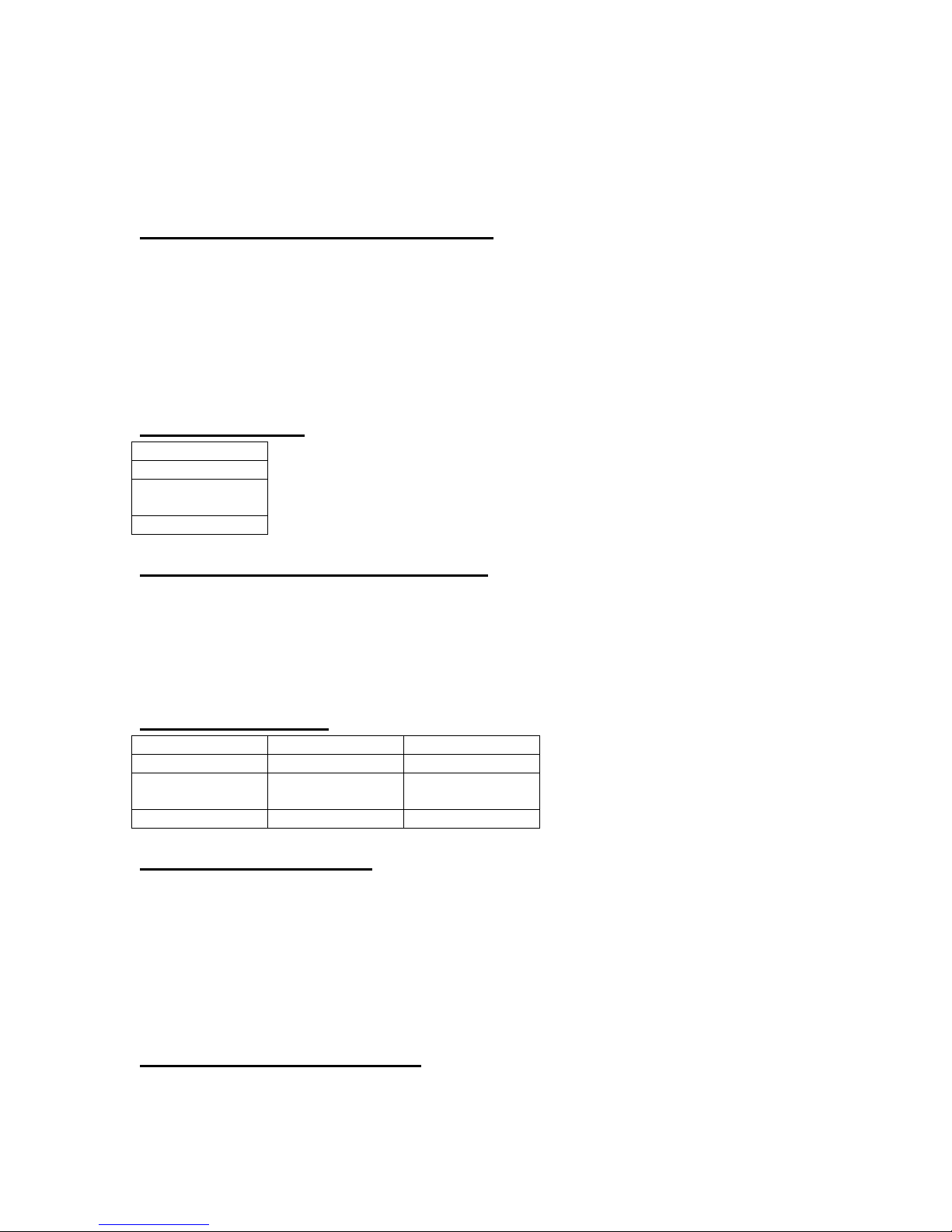
On: Sets the number of pulses to generate before inhibiting
-HGFE DCBA-
Multiplexed
Channels
Channel Enable
Channel Enable
Channel Enable
Ch Gate Mode:
(Gate Menu)
Ch Gate Mode:
Pulse Inhibit
Ch Gate Mode:
Output Inhibit
Logic Level
Logic Level
output in Duty Cycle Mode.
Off: Sets the number of pulses to inhibit before repeating the On
Cycle in Duty Cycle Mode.
Delaying the Start of Channel Output
Within any channel mode, the output of the channel can be delayed using the
wait parameter (within the CHANNEL menu):
Wait: Sets the number of T0 pulses to wait until enabling the
channel output.
Advanced Channel Menus (FUNC + A, B, C, D, E, F, G or H key)
Multiplexer Menu
Configuring the Channel Multiplexer
To define which channels are fed into the channel multiplexer, the corresponding
bit for the desired channel to add should be set to 1. All desired omitted
channels should have the corresponding bit set to 0.
Mux: Enable/disable bit field.
Channel Gate Menu
Setting the Sync Source
Although each channel receives its start pulse from the internal T0 pulse, the start
pulse can be assigned such that the delay entered is relative to the T0 pulse or
any other channel pulse. This allows dependent events to link. The unit will not
allow a circular chain of sync sources that would result in a channel triggering
itself. The delay entered is relative to the selected sync source.
Sync Source: Selects the channel sync source.
Setting Channel Gate Control
When the global gate is set (Chan Menu), the channel can then use the gate
input with independent behavior from other channels.
Page 19
6-19
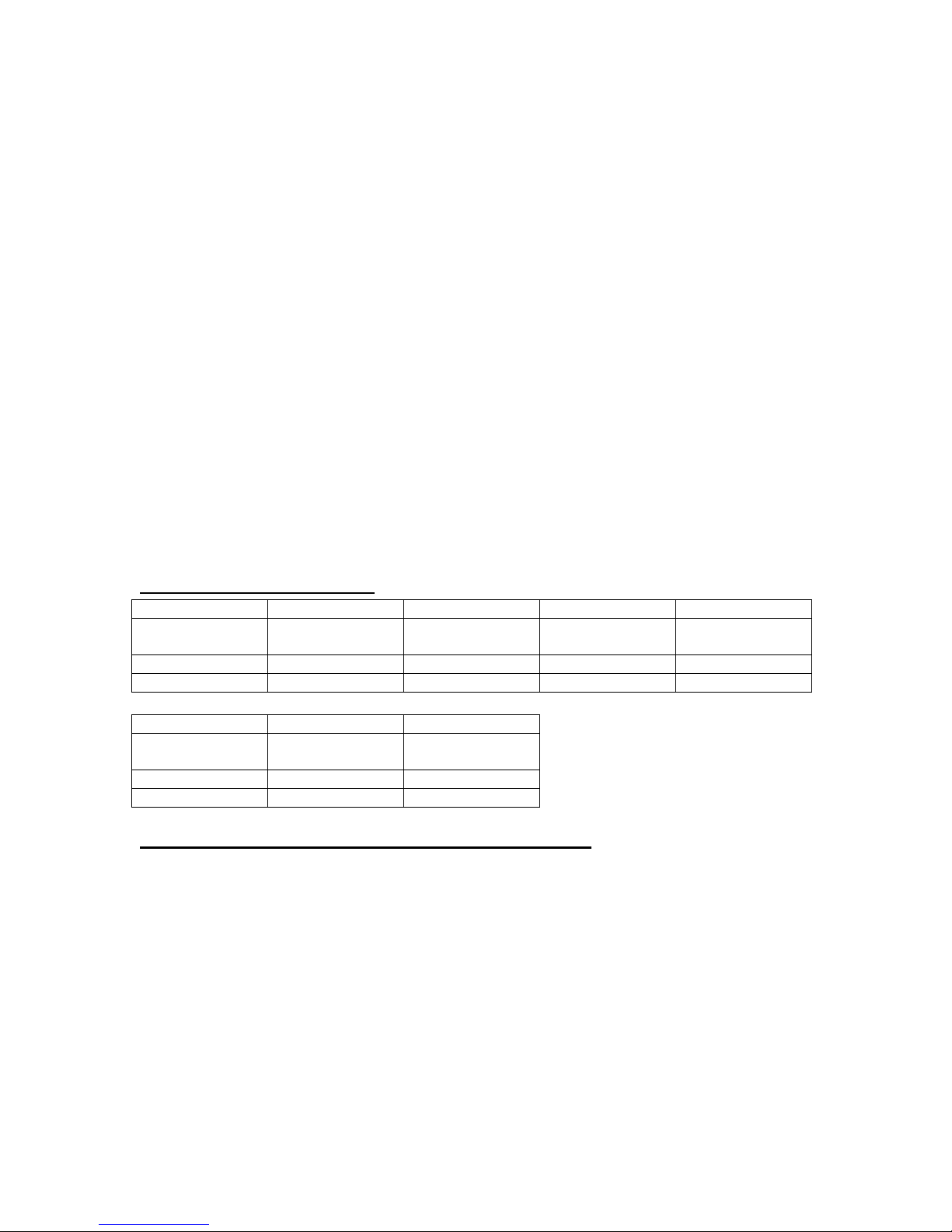
Source:
System Osc
Source:
10MHz Ext
Source:
20MHz Ext
Source:
25MHz Ext
Source:
40MHz Ext
T0 Period
T0 Period
T0 Period
T0 Period
T0 Period
Source:
50MHz Ext
Source:
80MHz Ext
Source:
100MHz Ext
T0 Period
T0 Period
Gate: Enables the GATE input for the channel by setting the
method of output control used with the gating
function.
Logic: Sets the logic level used with the gating function,
either active high or active low.
“Pulse Inhibit” method
The gate prevents the channel from being triggered by the channel’s
trigger source pulse. If a pulse has already started when the gate disables
the channel, the pulse will continue normal output but will not restart on
the next trigger pulse.
“Output Inhibit” method
The gate leaves the base triggering alone and enables/ disables the
output directly.
Clocks/Rate Menus (FUNC + RATE key)
Internal Reference Menu
Setting the Internal Reference Source and Rate
Source: Selects the internal or external clock source from
which the unit will operate.
To: Sets the T0 period which determines the fundamental
output frequency of the unit.
Page 20
6-20
Reference Out Menu
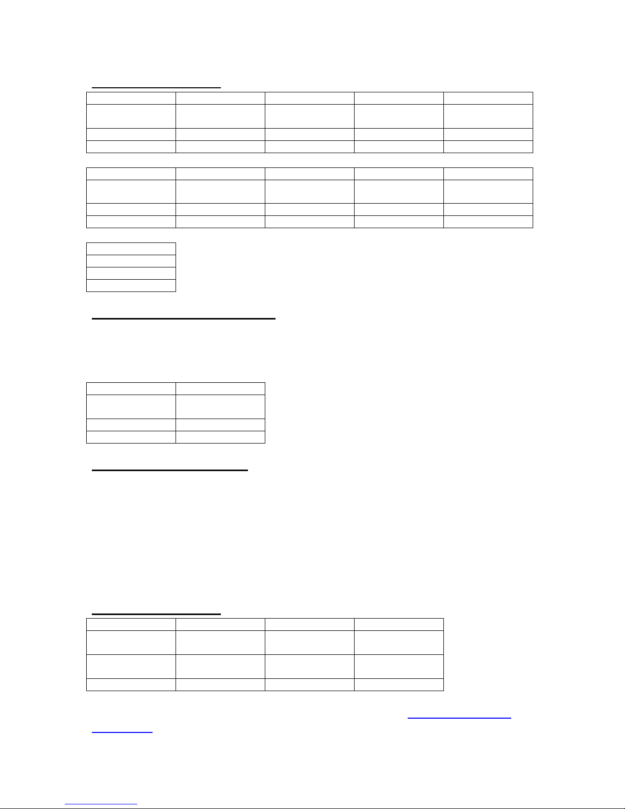
Ref Out: T0
Pulse
Ref Out:
100MHz
Ref Out: 50MHz
Ref Out:
33.33MHz
Ref Out: 25MHz
T0 Period
T0 Period
T0 Period
T0 Period
T0 Period
Ref Out: 20MHz
Ref Out:
16.67Mhz
Ref Out:
14.2857MHz
Ref Out:
12.5MHz
Ref Out:
11.11MHz
T0 Period
T0 Period
T0 Period
T0 Period
T0 Period
Ref Out: 10MHz
T0 Period
Mode: Disabled
Mode:
Triggered
Threshold Level
Trigger Edge
Mode: Disabled
Mode: Pulse
Inhibit
Mode: Output
Inhibit
Mode: (Chan
Menu) *
Threshold
Level
Threshold
Level
Threshold Level
Logic Level
Logic Level
Setting the Output Reference
Ref Out: Selects the frequency of the output reference for
syn-chronizing with external system components.
Trigger Menus (TRIG key)
Enabling System Trigger
Enable the use of the TRIG input by the system timer as a trigger source.
Mode: Selects between disabling/enabling the trigger mode.
Level: Sets the trigger threshold. Edge: Selects between
rising and falling edges as the trigger source when a
trigger mode is enabled.
Gate Menus (GATE key)
Standard Gate Menu
* Gate Mode is controlled on a per channel basis from the Advanced Channel
Gate Menu
Page 21
6-21
Enabling System Gate
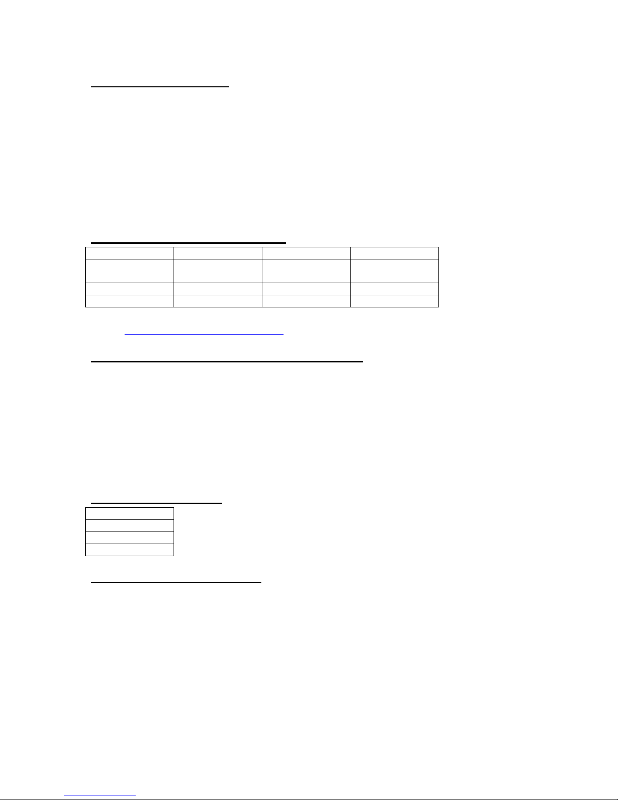
Interface:
RS232
Interface: USB
Interface: GPIB
*
Interface:
Ethernet *
Baud Rate
Address
Echo
Key Rate
Key Volume
Knob Volume
Enables the use of the GATE input as a trigger inhibit or output control for all
channels simultaneously, or on a per channel basis.
Mode: Selects between disabling the GATE inputs and
method of output control
Level: Sets the gating threshold.
Logic: Sets the active logic level.
System Configuration Menus (FUNC + SYSTEM key)
Communication Interface Menu
* Instrument must be equipped with the Extended Communications Option.
(Visit www.berkeleynucleonics.com for more details).
Setting System Communication Parameters
The 575 comes with a standard RS232 serial port and USB port. The unit will not
respond to computer commands unless these ports are properly configured.
Interface: RS232, USB, GPIB (optional), Ethernet (optional)
Baud Rate: Selects the baud rate for the selected interface.
Echo: Selects whether to echo characters back to the host
computer or not. Address: Sets the GPIB address.
User Options Menu 1
Setting Keypad Parameters
The rate at which a key will repeat itself when held down may be set. This can be
used to provide a controlled rate at which a parameter is incremented. In
addition, the volume of the beep can be controlled for both the keypad and the
adjustable knob.
Key Rate: Sets the rate at which the keys will repeat when held
Key Vol: Sets the beep volume for the keypad.
Knob Vol: Sets the beep volume for the Rotary Knob.
down.
Page 22
6-22
User Options Menu 2
Auto Start
Mode
Decimal Mark
LCD Brightness
Configuration #
Name
Help Line
Setting the Auto Start Mode
The unit may be configured to automatically start generating pulses after power
up.
Setting the Display Decimal Mark
Mark: Selects the format of the decimal mark, “.” or “,”.
Setting the Display Brightness
LCD: Adjusts display brightness.
Store Menu (FUNC + STORE key)
Storing a Configuration
Use the following procedure to store a complete system configuration:
Set all parameters to the desired value.
Select a configuration number.
*NOTE: You cannot store to the zero location, as that contains the factory default
values.
Label the configuration as desired.
From the Store menu, press the store button sequence (FUNC + STORE).
Page 23
6-23
Recall Menu (FUNC + RECALL key)
Configuration #
Name
Help Line
Counter Enable
Counter Enable
T Counts
T Counts
G Counts *
Help Line
Help Line
Model Number
Serial Number
Firmware Ver.
FPGA Ver.
FW ID #
GA ID #
Module IDs
Instr. Options
Recalling System Configurations
Use the following procedure to recall a stored or default system configuration:
Enter the Recall Menu (FUNC + RECALL).
Select a configuration number.
From the Recall Menu, press the recall key sequence (function + recall).
*Note: Configuration 0 is the factory default setting.
Counter Menu (FUNC + AUX1 key)
* Enabled when the Trigger Mode is set to Dual Trigger operation
(Instrument must be equipped with the Dual Trigger Option. Visit
www.berkeleynucleonics.com for more details).
Using the Counter Function
The Counter function counts the number of T0 pulses output by the system clock.
When the unit is operated in system single shot mode, the T0 count reflects the
number of incoming trigger pulses.
Information Menus (FUNC + 0 key)
Information Menu A
Information Menu B
The Information Menus provide all of the pertinent version numbers and serial
numbers for the unit. This information should be readily available when
contacting customer service for troubleshooting help.
Page 24

7-24
7 Operating the 575
Quick Start - Normal Internal Rate Generator Operation
The 575 has a powerful set of functions providing a number of modes of
operation for the internal or “System” rate generator (T0). Most of these functions
can be ignored if a simple continuous stream of pulses is required. Starting from
the default settings, which can be restored by recalling configuration 0, the
following parameters need to be set:
Pulse Width, Delay Enter the Channel menus by pressing the letter key.
Enter the required pulse width and delay. Repeat for
each output channel.
T0 Period Enter the Rate menu by pressing the FUNC key and
then the RATE key. Set the desired pulse period.
Note that in general, the pulse delay plus the pulse
width, plus a 75ns hardware reset constant, for any
channel must be less than the T0 period.
Start Press the RUN/STOP key to start generating pulses.
Stop Press the RUN/STOP key a second time to stop
gen-erating pulses.
Quick Start - Normal External Trigger Operation
To generate a single pulse for every external trigger event, based on the default
configuration 0, the following parameters need to be set:
System Mode Enter the System Mode menu by pressing the FUNC
key and then the MODE key. Select Single Shot
mode.
Trig Enter the Trigger menu by pressing the TRIG key.
Select Triggered.
Level Press the NEXT key until the Level parameter is
highlighted. Set the trigger threshold voltage to
approximately 50% of the trigger signal amplitude.
Edge Press the NEXT key until the Edge parameter is
high-lighted. Set the instrument to trigger off the rising
edge or falling edge as desired.
Page 25

7-25
Pulse Width, Delay Enter the Channel menus by pressing the letter key.
Enter the required pulse width and delay. Repeat for
each output channel.
Start Press the RUN/STOP key to start/arm the instrument.
The 575 will now generate a pulse for every valid
trigger.
Stop Press the RUN/STOP key a second time to
stop/dis-arm the instrument (i.e. to stop generating
pulses).
System Timer Overview
For internal operation, the 575 contains a timer and mode generator which
generates an internal T0 clock that is used to trigger all the channel timers.
System modes are controlled via the MODE menu.
To Use Continuous Mode
The RUN/STOP button starts and stops a continuous pulse stream at the rate
specified by the Rate menu. This corresponds to the normal output mode for
most pulse generators.
To generate a continuous stream of pulses:
- within the system Mode menu
Mode Select Continuous for the system mode.
- within the Rate menu
Source Select the system oscillator or the external clock in
frequency.
Period Set the desired period.
Pressing the RUN/STOP key will now generate a stream of T0 pulses at a
rate specified by the period parameter.
To Use Single Shot Mode
To generate a single pulse with every press of the RUN/STOP key:
- within the system Mode menu
Mode Select Single Shot for the system mode.
Pressing the RUN/STOP key will now generate a single pulse.
To Use System Burst Mode Function
The RUN/STOP button generates a stream of “n” T0 pulses, where “n” is
speci-fied by the Burst parameter. The rate is specified in the Rate menu.
Page 26

7-26
Pressing the RUN/STOP button while the burst is in process will stop the output.
After the burst has been completed, pressing the RUN/STOP button will generate
an-other burst. T0 generate a burst of pulses:
- within the system Mode menu
Mode: Select the Burst mode.
Burst: Set the number of pulses to produce in the burst.
To Use System Duty Cycle Function
The RUN/STOP button starts a continuous pulse stream which oscillates on for
the “n” pulses and off for “m” pulses, where “n” and “m” are specified by the On
and Off parameters, respectively. The rate is specified in the Rate Menu. To
generate a stream of pulses which oscillates on for ‘n’ pulses and off for ‘m’
pulses:
- within the system Mode menu
Mode: Select the Duty Cycle mode.
On: Set the number of pulses to produce during the on
cycle.
Off: Set the number of pulses to skip during the off cycle.
- within the Rate menu
Source: Select the system oscillator or the external clock in
frequency.
Period: Set desired Period.
Channel Timer Overview
The output of each channel is controlled by two timers to generate the delay
timing and the pulse width. All channels are simultaneously triggered, depending
on the system mode, by the internal T0 pulse, the external trigger, or a trigger
provided by the operating software. A given channel may or may not generate a
pulse depending on its own channel mode as described below.
When one channel is generating a continuous stream of pulses, a user
can trigger a single shot or burst of pulses on another channel without
interrupting the continuous stream by pressing the FUNC and the
RUN/STOP key.
To Use Channel Normal Mode Function
The Normal mode generates a continuous stream of pulses at a rate determined
by the system timer:
- within the Channel menus
Enable: Select Enable to enable channel output.
Dly: Set the desired delay.
Wid: Set the desired pulse width.
Page 27

7-27
Mode: Select the Normal mode.
Pressing the RUN/STOP key will now generate a continuous stream of pulses.
To Use Channel Single Shot Function
The Single Shot mode generates a single pulse every time the RUN/STOP key is
pressed. If the unit is in the active state, ( i.e. channels which are set to the
Normal mode are producing pulses), pressing the FUNC key and RUN/STOP
key will reset the Single Shot counters and generate one pulse in sync with the
other channels running in the Normal mode. To use the Single Shot mode:
- within the Channel menus
Enable: Select "Enabled" to enable channel output.
Delay: Set the desired delay.
Width: Set the desired pulse width.
Mode: Select the Single shot mode.
To Use Channel Burst Mode Function
The Burst mode generates a burst of pulses every time the RUN/STOP key is
pressed. If the unit is in the active state, (i.e. channels which are set to the
Normal mode are producing pulses), pressing the FUNC - RUN/STOP key
sequence will reset the Burst counters and generate a new set of pulses in sync
with the other channels running in the Normal mode. FUNC - RUN/STOP will not
affect T0 pulse status. To use the Burst mode:
- within the Channel menus
Enable: Select “Enabled” to enable channel output.
Delay: Set the desired delay.
Width: Set the desired pulse width.
Mode: Select the Burst mode.
#/Burst: Set the number of pulses to produce in the burst.
To Use the Channel Duty Cycle Function
To generate a stream of pulses which oscillates on for ‘n’ pulses and off for ‘m’
pulses:
- within the Channel menus
Enable: Select “Enabled” to enable channel output.
Delay: Set the desired delay.
Width: Set the desired pulse width.
Mode: Select the Duty Cycle mode.
On Cycle: Set the number of pulses to produce during the on
Off Cycle: Set the number of pulses to skip during the off cycle.
*Note: Older Berkeley Nucleonics pulse generators had a divide-by-n func-tion.
The duty cycle mode is a more general case. To reproduce the divide-by-n
cycle.
Page 28

7-28
function, set the on cycle to 1 and set the off cycle to (n-1), where “n” is the
divide-by-n factor.
To Use the Channel Gating Function
Each channel may use the external input to gate or control its output. The gate
controls the triggering of the channel. To use the gate, set the following
parameters
- within the Channel menu
Mode: In Gate Menu must be set to Channel Menu.
Channel Gate: Select “Pulse Inh” or “Output Inh”.
Logic: Select active high or active low.
In the “Pulse inhibit” method, the gate prevents the channel from being
triggered by the channel’s trigger source pulse. If a pulse has already
started when the gate disables the channel, the pulse will continue normal
output but will not restart on the next pulse. In the “Output inhibit” method,
the gate leaves the base triggering alone and enables/disables the output
directly. Output pulses will immediately cease when the gate signal is
removed
External Input Overview
The external inputs may be used to trigger the unit or to gate the system or
channel timers. When using a trigger input, the external input acts as a system
start pulse. Depending on the system mode, the result of a trigger input can be
either a single pulse, a burst of pulses or the start of a stream of pulses.
To Generate a Pulse on Every Trigger Input
To generate a pulse on every external trigger received, set the following
param-eters:
- within the Mode menu
Mode: Select the Single Shot mode.
- within the Trigger menu
Mode: Select Triggered mode.
Level: Set the trigger threshold level.
Edge: Select which edge, rising or falling, to trigger on.
Pressing the RUN/STOP key will arm the unit. Once the unit is armed, it
will generate a T0 pulse for every external trigger received. Pressing the
RUN/STOP key will disarm the unit. This mode corresponds to the normal
external trigger mode found on most other pulse generators.
Page 29

7-29
To Generate a Burst of Pulses on Every Trigger Input
To generate a burst of pulses for every external trigger received set the following
parameters:
- within the Mode menu
Mode: Select the Burst mode.
Burst: Set the number of pulses to generate in each burst.
- within the Rate menu
To: Set the period between pulses.
- within the Rate menu
Source: Select the system oscillator or an external clock in
frequency.
To: Set the period between pulses.
- within the Trigger menu
Mode: Select Triggered mode.
Level: Set the trigger threshold level.
Edge: Select which edge, rising or falling, to trigger on.
Pressing the RUN/STOP key will arm the unit. Once the unit is armed, it
will generate a set of pulses for every external trigger received. The unit is
reset at the end of a burst and will generate another set of pulses upon
receiving a new trigger. Triggers that occur in the middle of a burst are
ignored. Pressing the RUN/STOP key will disarm the unit.
To Start a Continuous Stream of Pulses Using the External Trigger
The external trigger may be used to start the unit generating pulses:
- within the Mode menu
Mode: Select the Continuous mode.
- within the Rate menu
Source: Select the system oscillator or an external clock in
frequency.
To: Set the period between pulses.
- within the Trigger menu
Mode: Select the Trigger mode.
Level: Set the trigger threshold level.
Edge: Select which edge, rising or falling, to trigger on.
Pressing the RUN/STOP key will arm the unit. Once the unit is armed, it
will begin generating pulses after an external trigger is received. Triggers
Page 30

7-30
that occur after the pulses start are ignored. Pressing the RUN/STOP key
a second time will disarm the unit.
To use the External Gate to Control the System
The external gate may be used to control the output of the unit. To gate the
system timer:
- within the Mode menu
Mode: Select the desired mode.
- within the Rate menu
Source: Select the system oscillator or an external clock in
frequency.
Per: Set the period between pulses.
- within the Gate menu
Mode: Select “Pulse Inh” or “Output Inh”.
Level: Set the gate threshold level.
Logic: Select active high or active low.
Pressing the RUN/STOP key will arm the unit. Once the unit is armed, it
will begin generating pulses whenever the external gate input is in the
active state. Pressing the RUN/STOP key a second time will disarm the
unit.
Page 31

8-31
8 Programming the 575
Personal Computer to Pulse Generator Communication
The 575 ships standard with an RS232 serial and USB interface. Ethernet and
GPIB interfaces are available as an option. All menu settings can be set and
retrieved over the computer interface using a simple command language. The
command set is structured to be consistent with the Standard Commands for
Programmable Instruments. Although due to the high number of special features
found in the 575, many of the commands are not included in the specification.
The syntax is the same for all interfaces. The amount of time required to receive,
process, and respond to a command at a Baud rate of 115200 is approximately
10 ms. Sending commands faster than 10 ms may cause the unit to not respond
properly. It is advised to wait until a response from the previous command is
received before sending the next command.
WARNING: When communicating with the unit (USB, Serial or Ethernet), avoid
sending any commands that include the “*” character as the unit is booting up.
This may result in an undesired lockup of the instrument.
RS232 Interface Overview
The serial port is located on the back of the 575 and uses a 9-pin D-type
connector with the following pinout (as viewed from the back of the unit):
1 No Connection
2 Tx - Transmit (to computer)
3 Rx - Receive (from computer)
4 DTR - Connected to pin 6
5 Ground
6 DSR - Connected to pin 4
7 RTS - Connected to pin 8
8 CTS - Connected to pin 7
9 No Connection
The serial port parameters should be set as follows:
Baud Rate 4800, 9600 19200, 38400, 57600, 115200*
Data Bits 8
Parity None
Stop Bits 1
*The default baud rate for the RS232 is 115200.
Page 32

8-32
USB Interface Overview
The USB interface is standard on the 575. Before this type of communication can
be used, the appropriate drivers must be installed on the personal computer (pc).
These drivers are included on the CD that was shipped with your unit. Please
contact Berkeley Nucleonics or visit www.berkeleynucleonics.com for updated
installation files and instructions.
USB communication is achieved by using a mapped (virtual) COM port on the
PC. The driver installation executable will obtain an unused COM port number,
install the USB drivers, and make that COM port number available for typical
RS232 communication to the pulse generator. HyperTerminal or other common
software may be used.
When communicating through the mapped COM port over USB, the baud rate for
the communication port used by the USB chip must match the baud rate for the
COM port on the PC. Access to the USB port baud rate is done using the SCPI
command “:SYSTem:COMMunicate:SERial:USB <baud rate>” command. This
parameter can be accessed via any communication method. The default baud
rate for USB is 38400.
USB communication notes:
The correct drivers must be installed on the personal computer before
communication can be accomplished via USB.
The BAUD rates on the PC and on the pulse generator must match for
successful communication.
The USB port’s BAUD rate on the pulse generator can be set using the
SCPI command “:SYSTem:COMMunicate:SERial:USB <baud rate>”
where <baud rate> can be:
o 4800
o 9600
o 19200
o 38400 (default)
USB 1.0 specification is used. The USB cable can be removed without
“unplugging” the device in the operating system environment.
Echo functionality is not available on the USB port.
GPIB Interface Overview
A GPIB interface is optional on the 575. Refer to Appendix C for more
information.
Ethernet Interface Overview
An Ethernet interface is optional on the 575. Refer to Appendix C for more
information.
Page 33

8-33
Programming Command Types and Format
The 575 Pulse Generator uses two types of programming commands: IEEE
488.2 Common Commands and Standard Commands for Programmable
Instruments (SCPI). The format is the same for all interfaces. HyperTerminal (in
Windows) or any other generic terminal program may be used to interactively test
the commands using the RS232 interface. The format of each type is described
in the following paragraphs.
Line Termination
The pulse generator uses text-style line terminations. When a command is sent
to the unit, the firmware is programmed to read characters from a communication
port until it reads the line termination sequence.
The command string is parsed and executed after reading these characters.
These characters are the “carriage return” and “linefeed”. They are ASCII
char-acter set values 13 and 10 respectively (hex 0x0D and 0x0A). All command
strings need to have these characters appended.
When the pulse generator responds to a command, whether it is a query or a
parameter change, it also appends its return strings with these characters.
Coded applications could use this behavior to know when to stop reading from
the unit. However, if the “echo” parameter is enabled, there will be two sets of
line terminators, one following the echoed command string, and one following the
pulse generator’s response.
Note: The pulse generator will echo commands on the DB9 serial port only.
The pulse generator responds to every communication string. If the
communica-tion string is a query, the unit responds with the queried response (or
error code) followed by the line terminators. If the communication string is a
parameter change, the response is “ok” (or error code) followed by the line
terminators. For this reason, it is not recommended that multiple commands be
stacked together into single strings as is common with some other types of
instruments. It is recommended that the coded application send a single
command in a string and follow immediately by reading the response from the
unit. Repeat this sequence for multiple commands.
IEEE 488.2 Common Command Format
The IEEE 488.2 Common Commands control and manage generic system
functions such as reset, configuration storage and identification. Common
commands always begin with the asterisk (*) character and may include
param-eters. The parameters are separated from the command pneumonic by a
space character. For Example:
*RST<cr><lf>
*RCL 1<cr><lf>
Page 34

8-34
*IDN?<cr><lf>
SCPI Command Format
SCPI Command Keywords
The commands are shown as a mixture of upper and lower case letters. The
upper case letters indicate the abbreviated spelling for the command. You may
send either the abbreviated version or the entire keyword. Upper and/or lower
case characters are acceptable.
For example, if the command keyword is given as POLarity, then POL and
POLARITY are both acceptable forms; truncated forms such as POLAR will
generate an error; polarity, pol, and PolAriTy are all acceptable as the pulse
generator is not case sensitive.
SCPI Command Format
SCPI commands control and set instrument specific functions such as setting the
pulse width, delay and period. SCPI commands have a hierarchical struc-ture
composed of functional elements that include a header or keywords sepa-rated
with a colon, data parameters, and terminators. For example:
SCPI Format
:PULSE1:STATE ON<cr><lf>
:PULSe1:WIDTh 0.000120<cr><lf>
:PULSe:POL NORMal<cr><lf>
Any parameter may be queried by sending the command with a question mark
appended. For example:
- QUERY FORMAT
:PULSE1:STATE?<cr><lf>
Will return: 1<cr><lf>
:PULSE1:WIDT?<cr><lf>
Will return: 0.000120000<cr><lf>
:PULSE1:POL?<cr><lf>
Will return: NORM<cr><lf>
SCPI Keyword Separator
A colon (:) must always separate one keyword from the next lower-level
key-word. A space must be used to separate the keyword header from the first
parameter. If more than one parameter is used, you must separate subsequent
parameters with a comma.
Page 35

8-35
SCPI Optional Keywords
Optional keywords and/or parameters appear in square brackets ( [ ] ) in the
command syntax. Note that the brackets are not part of the command and should
not be sent to the pulse generator. When sending a second level key-word
without the optional keyword, the pulse generator assumes that you intend to use
the optional keyword and responds as if it had been sent.
SCPI Specific and Implied Channel
Some commands, such as PULSe, allow specifying a channel with an optional
numeric keyword suffix. The suffix will be shown in square brackets [ 1 / 2 ]. The
brackets are not part of command and are not to be sent to the pulse generator.
The numeric parameters correspond to the following channels: 0 = T0, 1 = ChA,
2 = ChB, etc. Only one channel may be specified at a time.
If you do not specify the channel number, the implied channel is specified by the
:INSTrument:SELect command or the last referenced channel.
After power-up or reset (*RST) the instrument default is channel #1.
SCPI Parameter Types
The following parameter types are used:
<numeric value> Accepts all commonly used decimal representation of
numbers including optional signs, decimal points, and
scientific notation: 123, 123e2, -123, -1.23e2, .123,
1.23e-2, 1.2300E-01.
<boolean value> Represents a single binary condition that is either true
or false. True is represented by a 1 or ON; false is
rep-resented by a 0 or OFF. Queries return 1 or 0.
<identifier> Selects from a finite number of predefined strings.
Error Codes
The unit responds to all commands with either:
ok<cr><lf> or ?n<cr><lf>
Where "n" is one of the following error codes:
1 Incorrect prefix, i.e. no colon or * to start command.
2 Missing command keyword.
3 Invalid command keyword.
4 Missing parameter.
5 Invalid parameter.
6 Query only, command needs a question mark.
7 Invalid query, command does not have a query form.
8 Command unavailable in current system state.
Page 36

8-36
Programming Examples
Example 1)
20 ms pulse width, 2.3 ms delay, 10 Hz, internal trigger, continuous
operation.
:PULSE1:STATE ON<cr><lf> enables channel A
:PULSE1:POL NORM<cr><lf> sets polarity to active high
:PULSE:WIDT 0.020<cr><lf> sets pulse width to 20 ms
:PULSE1:DELAY 0.0023<cr><lf> sets delay to 2.3 ms
:PULSE0:MODE NORM<cr><lf> sets system mode to continuous
:PULSE0:PER 0.1<cr><lf> sets period to 100 ms (10 Hz)
:PULSE0:TRIG:MODE DIS<cr><lf> disables the external trigger
To start the pulses use either of the following commands:
:PULSE0:STATE ON<cr><lf> starts the pulses
:INST:STATE ON<cr><lf> alternate form to start pulses
Example 2)
25µs pulse width, 0 delay, external trigger, one pulse for every trigger.
:PULSE1:STATE ON<cr><lf> enables channel A
:PULSE1:POL NORM<cr><lf> sets polarity to active high
:PULSE:WIDT 0.000025<cr><lf> sets pulse width to 25µs
:PULSE1:DELAY 0<cr><lf> sets delay to 0
:PULSE0:MODE SING<cr><lf> sets system mode to single shot
:PULSE:TRIG:MODE TRIG<cr><lf> sets system to external trigger
:PULS:TRIG:LEV 2.5<cr><lf> sets trigger level to 2.5 v
:PULS:TRIG:EDGE RIS<cr><lf> set to trigger on rising edge
To arm the instrument in external gate mode, use either of the following
commands:
:PULSE0:STATE ON<cr><lf> arms the instrument
:INST:STATE ON<cr><lf> alternate form if T0 is currently
A software generated external trigger can be generated by using the
following command:
*TRG<cr><lf> generates a software external
selected
trigger
Page 37
8-37
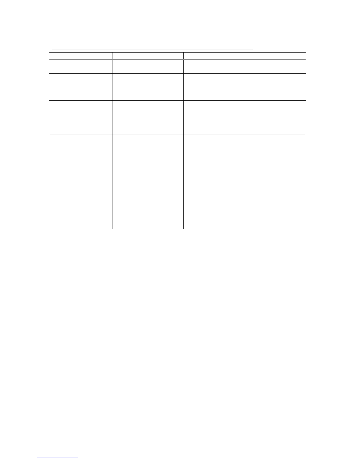
575 INSTrument Commands (SCPI Command Summary)
Keyword
Parameter
Comments
:INSTrument
Subsystem. Supports treating each
channel as a logical instrument.
:CATalog?
Query only. Returns a comma-separated
list of the names of all channels. A two
channel instrument would return:
T0,CHA,CHB.
:FULL?
Query only. Returns a comma-separated
list of the names of all channels and their
associated number. A two channel
instrument would return: T0 , 0, CHA, 1,
CHB, 2.
:COMMands?
Query only. Returns an indented list of all
SCPI commands.
:NSELect
0-8
Selects a channel using the channel's
numeric value. All channel specific
commands will refer to the selected
channel.
:SELect
T0,CHA,CHB,CHC,CHD,
CHE,CHF,CHG,CHH
Selects a channel using the channel's
identifier string. All subsequent channel
specific commands will refer to the
selected channel.
:STATe
0/1 or ON/OFF
Enables/Disables the selected channel
output. If T0 is selected all output is
affected. Enabling T0 is the same as
pressing the RUN button.
Page 38
8-38
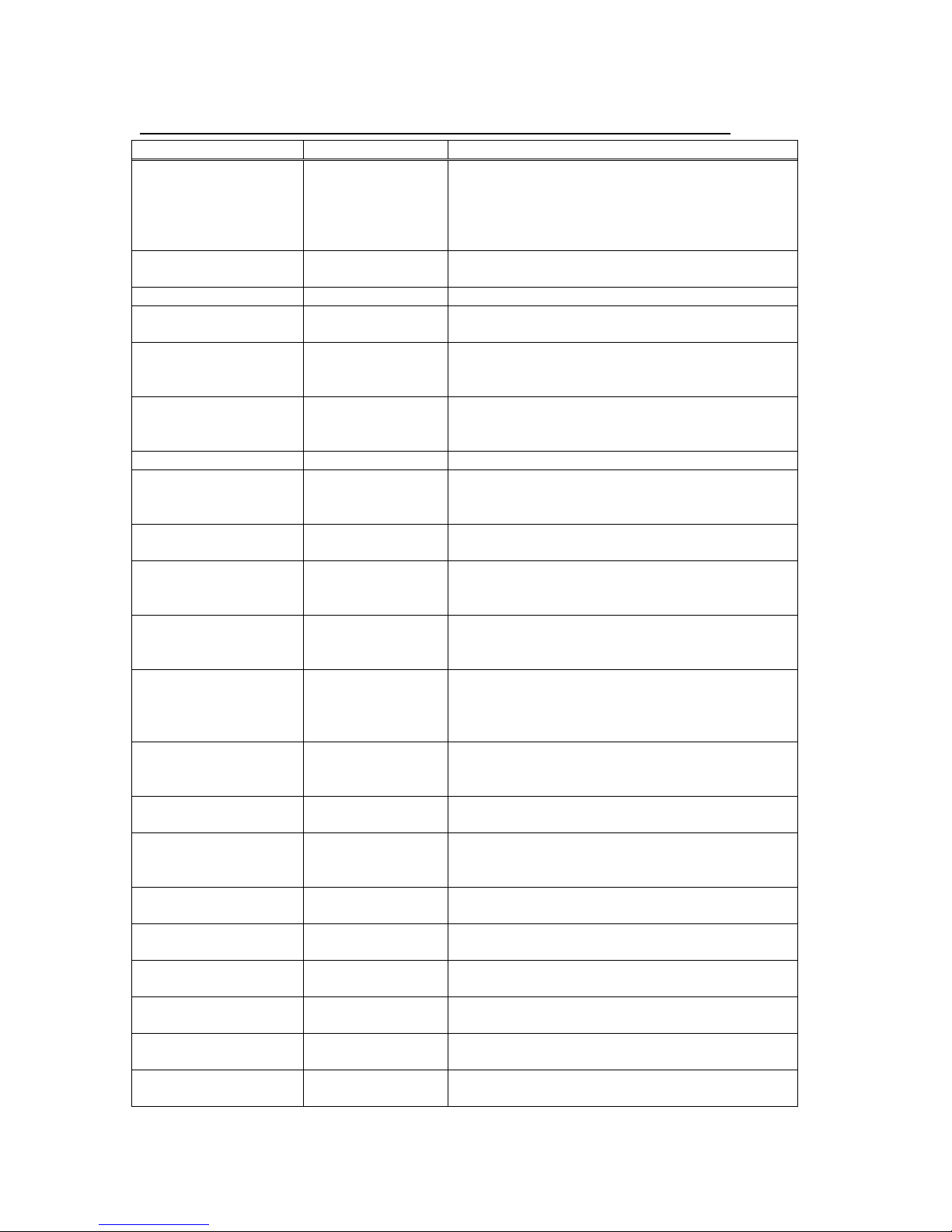
575 System PULSe[0] Commands (SCPI Command Summary)
Keyword
Parameter
Comments
:PULSe[0]
Subsystem. Contains commands to control
the output pulse generation. Commands
without suffix refer to the currently selected
logical instrument. See INSTrument
subsystem.
:COUNter
Subsystem. Contains commands to define
the Counter function.
:STATe
0/1 or ON/OFF
Enables/Disables the counter function.
:CLear
TCNTS/GCNTS
Clears the designated counter. Standard
units only have the Trigger counter.
:COUNts
TCNTS/GCNTS
Queries the number of counts for the
specified input. Standard units only have the
Trigger counter.
:STATe
0/1 or ON/OFF
Enables / Disables the output for all
channels. Command is the same as
pressing the RUN/STOP button.
:PERiod
100ns-5000s
Sets the T0 period.
:MODe
NORMal /
SINGle / BURSt /
DCYCle
Sets the T0 mode.
:BCOunter
1-9,999,999
Burst Counter. Number of pulses to generate
in the Burst mode.
:PCOunter
1-9,999,999
Pulse Counter. Number of pulses to
generate during on cycle of the Duty Cycle
mode.
:OCOunter
1-9,999,999
Off Counter. Number of pulses to inhibit
output during the off cycle of the Duty Cycle
mode.
:ICLock
SYS / EXT10 /
EXT20 / EXT25 /
EXT40 / EXT50 /
EXT80 / EXT100
Sets Source for the internal rate generator.
System Clock or External Source ranging
from 10MHz to 100MHz.
:OCLock
T0 / 10 / 11 / 12 /
14 / 16 / 20 / 25 /
33 / 50 / 100
Sets external clock output. T0 Pulse or 50%
duty cycle TTL output from 10MHz to
100MHz.
:GATe
Subsystem. Contains the commands to
define the Gate function.
:MODe
DISabled /
PULSe / OUTPut
/ CHANnel
Sets Global Gate Mode. Disable, pulse
inhibit, output inhibit, channel.
:LOGic
LOW / HIGH
Sets Channel Gate logic level. Active low or
active high.
:LEVel
.20V - 15V
Sets the gate threshold. Value is in volts
with a range of .20 to 15 Volts.
:TRIGger
Subsystem. Contains the commands to
define the Trigger function.
:MODe
DISabled /
TRIGgered
Sets Trigger Mode. Disable or TRIG (enable).
:LOGic
RISing / FALLing
Selects which edge (rising or falling) to use
as the trigger signal.
:LEVel
.20V - 15V
Sets the Trigger Threshold. Value is in volts,
with a range of .20 to 15 Volts.
Page 39
8-39
575 Channel PULSe[n] Commands (SCPI Command Summary)
Keyword
Parameter
Comments
:PULSe [1 / 2 / n]
Subsystem. Contains commands to control
the output pulse generation. Valid suffix
range depends on the number of channels
(ChA = 1, ChB = 2, etc). Command without
suffix refers to the currently selected logical
instrument. See INSTrument subsystem.
:STATe
0/1 or ON/OFF
Enables/Disables the output pulse for
selected channel.
:WIDTh
10ns -
999.99999999975s
Sets the width or duration of the output
pulse.
:DELay
-
999.99999999975s
-
999.99999999975s
Sets the time from the start of the T0 period
to the first edge of the pulse.
:SYNC
TO, CHA, CHB,
CHC, CHD, etc.
Selects the Sync source.
:MUX
0-255
Selects which timers are enabled as output
for the current channel.
:POLarity
NORMal /
COMPlement /
INVerted
Sets the polarity of the pulse. For NORMal
operation the second nominal state is more
positive than the first. COMPlement and
INVerted are aliases. For both, the second
state is more negative than the first.
:OUTPut
Subsystem. Contains command to control
output mode.
:MODe
TTL/
ADJustable/
Selects output Amplitude mode: TTL/CMOS,
ADJustable.
:AMP
2.0V to 20V
Sets adjustable output level.
:CMODe
NORMal /
SINGle /
BURSt /
DCYCle
Channel Mode. Sets the channel pulse series
output mode.
:BCOunter
1-9,999,999
Burst Counter. Sets the number of pulses to
generate when channel is in the BURST
mode.
:PCOunter
1-9,999,999
Pulse Counter. Sets the number of pulses to
generate during the on cycle of the Duty
Cycle Mode.
:OCOunter
1-9,999,999
Off Counter. Number of pulses to inhibit
output during the off cycle of the Duty Cycle
mode.
:WCOunter
0-9,999,999
Sets the number of T0 pulses to delay until
enabling output.
:CGATe
DIS / PULS /
OUTP
Sets Channel Gate Mode. Disable, pulse
inhibit, output inhibit. (Global Gate Mode
must be set to CHAN for this command to be
available).
:CLOGic
LOW / HIGH
Sets Channel Gate Logic level. Active low or
active high. (Global Gate Mode must be set
to CHAN for this command to be available.
Page 40
8-40
575 SYSTem Commands (SCPI Command Summary)
Keyword
Parameter
Comments
:SYSTem
:STATe?
Query only. Returns the state of the
machine: returns "1" if the machine is armed
and/or generating pulses or "0" if the
machine has been disarmed.
:BEEPer
Subsystem. Controls the audible beeper.
:STATe
0/1 or ON/OFF
Enables/disables the beeper.
:VOLume
0 - 100
Range is 0 to 100, Sets the volume of the
beeper where 0 is off and 100 is maximum
volume.
:COMMunicate
Subsystem. Controls the RS232 and GPIB
interfaces.
:GPIB
Subsystem. Controls the physical
configuration of the GPIB port.
:ADDRess
1-15
Sets the GPIB of the instrument.
:SERial
Subsystem. Controls the physical
configuration of the RS232 port.
:BAUD
4800 / 9600 /
19200 / 38400 /
57600 / 115200 /
Sets the baud rate for both receiving and
transmitting using the DB9 RS232 port.
:USB
4800 / 9600 /
19200 / 38400
Sets the baud rate for communication when
using mapped comports for USB
communication. Default value is 38400.
:ECHo
0/1 or ON/OFF
Enables/Disables transmission of characters
received on the DB9 serial port.
:KLOCk
0/1 or ON/OFF
Locks the keypad.
:AUTorun
0/1 or ON/OFF
After power-up, unit will start generating
pulses .automatically
:VERSion?
Query only. Returns SCPI version number in
the form: YYYY.V ex. 1999.0
:SERN?
Query only. Returns the serial number.
:INFOrmation?
Query only. Returns model, serial number,
firmware version, and FPGA version
numbers.
:NSID?
Query only. Returns firmware and FPGA
identification numbers.
:CAPS
0/1 or ON/OFF
Forces unit to recognize commands only
sent in capital letters. 1 turns on the feature 0 disables the feature.
Page 41
8-41
575 DISPlay Commands (SCPI Command Summary)
Keyword
Parameter
Comments
:DISPlay
Subsystem. Contains commands to control
the display.
:MODe
0/1 or ON/OFF
Enables/Disables automatic display update.
When true, front panel display is updated
with serial command parameter changes.
Setting to false decreases response time.
:UPDate?
Query only. Forces update of display. Use
when mode is false.
:BRIGhtness
0-4
Controls intensity of display. Range is 0 to 4,
where 0 is off and 4 is full intensity.
:ENABle
0/1 or ON/OFF
Enables/Disables the display and front panel
lights. When Disabled the keylock is enabled
to prevent parameter changes from the front
panel.
Keyword
Parameter
Comments
*IDN?
Identification
Query
Queries the Pulse Generator Identification.
The ID will be in the following format:
manufacturer,model#,serial#,version#
*RCL
0-12
Restores the state of the Pulse Generator
from a copy stored in local nonvolatile
memory (0 through 12 are valid memory
blocks).
*RST
Reset Command
Resets the Pulse Generator to the default
state.
*SAV
1-12
Stores the current state of the Pulse
Generator in local nonvolatile memory (1
through 12 are valid memory blocks).
*TRG
Trigger
Generates a software trigger pulse.
Operation is the same as receiving an
external trigger pulse.
*LBL
Setup Label
Query Form returns the label of the last
saved or recalled configuration.
Command Form sets the label string for the
next "*SAV" command. String must be in
double quotes, 14 characters max.
*ARM
Channel Trigger
Reset
Resets channel triggers when channels are
set to single shot or burst mode. Functions
like pressing the function then run/stop
button.
IEEE 488.2 Common Commands
Page 42

A-1
Appendix A - 575 Specifications
INTERNAL RATE GENERATOR
RATE (T0 period) 0.0002 Hz to 20.000 MHz
RESOLUTION 10ns
ACCURACY Same as timebase
JITTER < 50 ps
SETTLING 1 period
BURST MODE 1 to 9,999,999 pulses
TIMEBASE 100 MHz, low jitter PLL
OSCILLATOR 50 MHz, 25ppm
SYSTEM OUTPUT MODES Single pulse, burst, duty cycle, external
gate/trigger
PULSE CONTROL MODES Internal rate generator, external
trigger/gate
PROGRAMMABLE TIMING GENERATOR
CHANNEL OUTPUT MODES Single shot, burst, duty cycle, normal
CONTROL MODES Internally triggered, externally triggered
and external gate. Each channel may be
independently set to any of the modes.
OUTPUT MULTIPLEXER Timing of any/all channels may be
multiplexed to any/all outputs.
WAIT FUNCTION 0 to 9,999,999 pulses
TIMEBASE Same as internal rate generator
WIDTHS
RANGE 10 ns-999.99999999975 s
ACCURACY 1 ns + 0.0001 x width
RESOLUTION 250 ps
DELAYS
RANGE 0-999.99999999975 s
ACCURACY 1 ns + 0.0001 x delay
RESOLUTION 250 ps
PULSE INHIBIT DELAY < 120 ns typical
OUTPUT INHIBIT DELAY < 50 ns typical
SYSTEM EXTERNAL TRIGGER/GATE INPUT(S)
TRIGGER INPUT
FUNCTION Generate individual pulses, start a burst
RATE DC to 1/ (200 ns + longest active pulse).
or continuous stream
Maximum of 5 MHz
Page 43

A-2
SLOPE Rising or Falling
GATE INPUT
MODE Pulse inhibit or output inhibit
POLARITY Active high/active low
MODULE SPECIFICATIONS
TTL/ADJUSTABLE DUAL CHANNEL OUTPUT MODULE
(Standard)
OUTPUT IMPEDANCE 50 ohm
TTL/CMOS MODE
OUTPUT LEVEL 4.0 V typ into 1 kohm
RISE TIME 3 ns typ (10% - 90%)
SLEW RATE > 0.5 V/ns
JITTER 50 ps RMS channel to channel
ADJUSTABLE MODE
OUTPUT LEVEL 2.0 to 20 VDC into 1 k ohm
1.0 to 10.0 VDC into 50 ohm
OUTPUT RESOLUTION 10 mV
CURRENT 200 mA typical, 400 mA (short pulses)
RISE TIME 15ns typ @ 20 V (high imp)
25ns typ @ 10 V (50 ohms)
(10% - 90%)
SLEW RATE >0.1 V/ns
OVERSHOOT <100 mV + 10% of pulse amplitude
TRIGGER/GATE DUAL INPUT MODULE (Standard)
Standard dual channel input module, providing one trigger input and one
gate input. May be used with the dual trigger firmware option to provide
two independent trigger sources.
THRESHOLD 0.2 to 15 VDC
MAXIMUM INPUT VOLT. 60 V Peak
IMPEDANCE 1.2K ohm
RESOLUTION 10 mV
Page 44

A-3
TRIGGER INPUT
SLOPE Rising or Falling
JITTER 800 ps RMS
INSERTION DELAY <160 ns
MINIMUM PULSE WIDTH 2 ns
GATE INPUT
POLARITY Active High/Active Low
FUNCTION Pulse Inhibit or Output Inhibit
CHANNEL BEHAVIOR Global w/Individual Channel
PULSE INHIBIT DELAY 12 0 ns
OUTPUT INHIBIT DELAY 50 ns
OPTICAL OUTPUTS
WAVELENGTH 820 nm or 1300 nm
MAXIMUM SIGNAL RATE 5 MBd
MAXIMUM LINK DIST. 1.5 km
CONNECTOR TYPE ST
OPTICAL INPUTS
WAVELENGTH 820 nm or 1300 nm
MAXIMUM SIGNAL RATE 5MBd
MAXIMUM LINK DIST. 1.5 km
CONNECTOR TYPE ST
INSERTION DELAY <300 ns
JITTER <1.4 ns RMS
EXTERNAL CLOCK IN/OUT
CLOCK IN FREQUENCIES 10 MHz – 100 MHz user selectable in
THRESHOLD 2.3 V
MAX INPUT VOLTAGE 5.5 V
DUTY-CYCLE 50% (Recommended)
FREQUENCY JITTER <10%
CLOCK OUT FREQUENCIES To or Ref out (10 MHz – 100 Mhz) user
GENERAL
COMMUNICATIONS USB/RS232
STORAGE 12 storage bins
DIMENSIONS 10.5” x 8.25” x 5.5”
WEIGHT 8 lbs
POWER 100 - 240 VAC
discrete values
selectable in discrete values
50/60 Hz <3A
Page 45

A-4
FUSE (Qty 2) 3.15A, 250 V Time-lag
OUTPUT MODULES
Standard
AT20 Dual channel, TTL/CMOS & Adjustable output module
Optional
L82 Dual channel, 820nm optical output module
L130 Dual channel, 1300nm optical output module
AT35 Dual channel, TTL/35 V high voltage output module
AT45 Dual channel, 45 V high and low impedance voltage output
module (limited to 4 channels)
TZ50 Dual channel, high current TTL/CMOS (for driving 50 ohm
loads) & adjustable output module
TZ35 Dual channel, high current TTL/CMOS (for driving 50 ohm
loads) & 35V high voltage output module
INPUT MODULES
Standard
IA15 Dual channel, 1 trigger / 1 gate input module
Optional
IL82 Dual channel, 820nm optical input module
IL130 Dual channel, 1300nm optical input module
System Options
I Incrementing (provides automatic high speed incrementing /
DT15 Dual Trigger Logic – provides additional trigger via gate input
COM Extended Communications – Adds Ethernet & GPIB
SRM Single Rackmount
DRM Dual Rackmount
*Other custom modules (LED drivers, higher voltages, current sources,
and alternative input circuits) available, call with your request.
decrementing of delay and/or pulse width for each channel)
Page 46

B-5
Appendix B - Safety Symbols
Safety Marking Symbols
Technical specifications including electrical ratings and weight are included within
the manual. See the Table of Contents to locate the specifications and other
product information. The following classifications are standard across all BNC
Pulse Generator products:
Indoor use only
Ordinary Protection: This product is NOT protected against the harmful
ingress of moisture.
Class 1 Equipment (grounded type)
Main supply voltage fluctuations are not to exceed +/-10% of the nominal
supply voltage.
Pollution Degree 2
Installation (overvoltage) Category II for transient overvoltages
Maximum Relative Humidity: <80% RH, non-condensing
Operating temperature range of 0o C to 40o C
Storage and transportation temperature of -40o C to 70o C
Maximum altitude: 3000 m (9843 ft.)
This equipment is suitable for continuous operation.
This section provides a description of the safety marking symbols that appear on
the instrument. These symbols provide information about potentially danger-ous
situations which can result in death, injury, or damage to the instrument and
other components.
Symbols Publications; Descriptions & Comments
IEC 417, No. 5031
Direct current - VDC may be used on rating labels.
IEC 417, No. 5032
Alternating current - For rating labels, the symbol is typically
replaced by V and Hz as in 230V, 50Hz. DO NOT USE VAC.
IEC 417, No. 5033
Both direct and alternating current.
IEC 617-2 No. 02-02-06
Three-phase alternating current .
Page 47

B-6
IEC 417, No. 5017
Earth (ground) terminal - Primarily used for functional earth
terminals which are generally associated with test and
measurement circuits. These terminals are not for safety earthing
purposes but provide an earth reference point.
IEC 417, No. 5019
Protective conductor terminal - This symbol is specifically reserved
for the protective conductor terminal and no other. It is placed at the
equipment earthing point and is mandatory for all grounded
equipment .
IEC 417, No. 5020
Frame or chassis terminal - Used for points other than protective
conductor and functional earth terminals where there is a
connection to accessible conductive terminals to advise the user of
a chassis connection.
I EC 417, No. 5021
Equipotentiality - Used in applications where it is important to
indicate to the operator that two or more accessible functional earth
terminals or points are equipotential - More for functional rather
than for safety purposes.
IEC 417, No. 5007
On (Supply) - Note that this symbol is a bar, normally applied in the
vertical orientation. It is not the number 1.
IEC 417, No. 5008
Off (Supply) - Note that this symbol is a true circle. It is not the
number 0 or the letter O.
IEC 417, No. 5172
Equipment protected by double insulation or reinforced insulation
(equivalent to Class II if IEC 60536).
Page 48
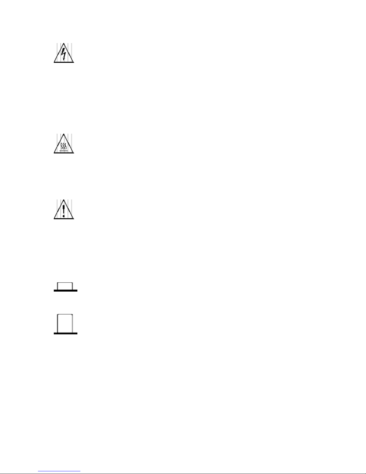
B-7
ISO 3864, No. B.3.6
Background colour - yellow; symbol and outline – black
Caution, risk of electric shock - Generally used only for voltages in
excess of 1000 V. It is permissible to use it to indicate lower
voltages if an explanation is provided in the manual. Colour
requirements do not apply to markings on equipment if the symbol
is molded or engraved to a depth or raised height of 0.5 mm, or that
the symbol and outline are contrasting in colour with the
background.
IEC 417, No. 5041
Background colour - yellow; symbol and outline – black
Caution, hot surface - Colour requirements do not apply to
markings on equipment if the symbol is moulded or engraved to a
depth or raised height of 0.5 mm, or that the symbol and outline are
contrasting in colour with the background.
ISO 3864, No. B.3.1
Background colour - yellow; symbol and outline – black
Caution - (refer to accompanying documents) used to direct the
user to the instruction manual where it is necessary to follow certain
specified instructions where safety is involved. Colour requirements
do not apply to markings on equipment if the symbol is moulded or
engraved to a depth or raised height of 0.5 mm, or that the symbol
and outline are contrasting in colour with the background.
IEC 417, No. 5268-a
In-position of bistable push control.
IEC 417, No. 5269-a
Out-position of bistable push control.
Page 49

C-8
Appendix C - COM Option
COM Overview
The COM Option for the 575 includes a GPIB and an Ethernet interface in
addition to the RS232 and USB interfaces included with the standard product.
The command set is the same for the RS-232, USB, GPIB, and Ethernet.
Different interfaces may be used at the same time. Responses will be made to
the most recently used interface.
GPIB Interface
Also known as IEEE-488, a GPIB computer interface is optional on the 575.
Before using this interface, the address must be set using the GPIB address
menu item.
Ethernet Interface
The Ethernet module used is a “Digi Connect ME” module supplied by Digi
Connectware, Inc. There are several ways to successfully communicate with the
pulse generator over Ethernet. The two most popular methods are raw TCP/IP
(such as LabView or programming with VISA libraries) and by mapping a PC
COM port using the Digi Connectware’s “Realport Drivers”.
IP Address and Raw TCP/IP Connection
This document describes one of the most popular methods of setting up Ethernet
communication for the Berkeley Nucleonics pulse generators. The method
discussed is Raw TCP/IP communication.
The Ethernet module used in Berkeley Nucleonics pulse generators is a “Digi
Connect ME” device manufactured by Digi International, Inc. It supports virtually
all practical Ethernet communication methods. A set of utilities and
documentation by Digi is included on the CD shipped with the pulse generator.
This discussion assumes that the Digi utilities included with your pulse generator
and National Instruments VISA (version 3.3 in this procedure, see National
Instruments’ website) are installed. The procedures discussed have been
prepared using Windows XP service pack 2.
Determining IP Address
The Digi module has been reset to factory defaults before it left the
manufactur-ing facility. In this mode, it is ready to be assigned an IP address by
the local DHCP server. If a crossover cable is being used, the Ethernet device
will as-sume a default IP address.
The Digi utility “Digi Device Discovery” can be used to determine the IP address
that is currently assigned to the Ethernet module. Hit “Start, All Programs, Digi
Page 50
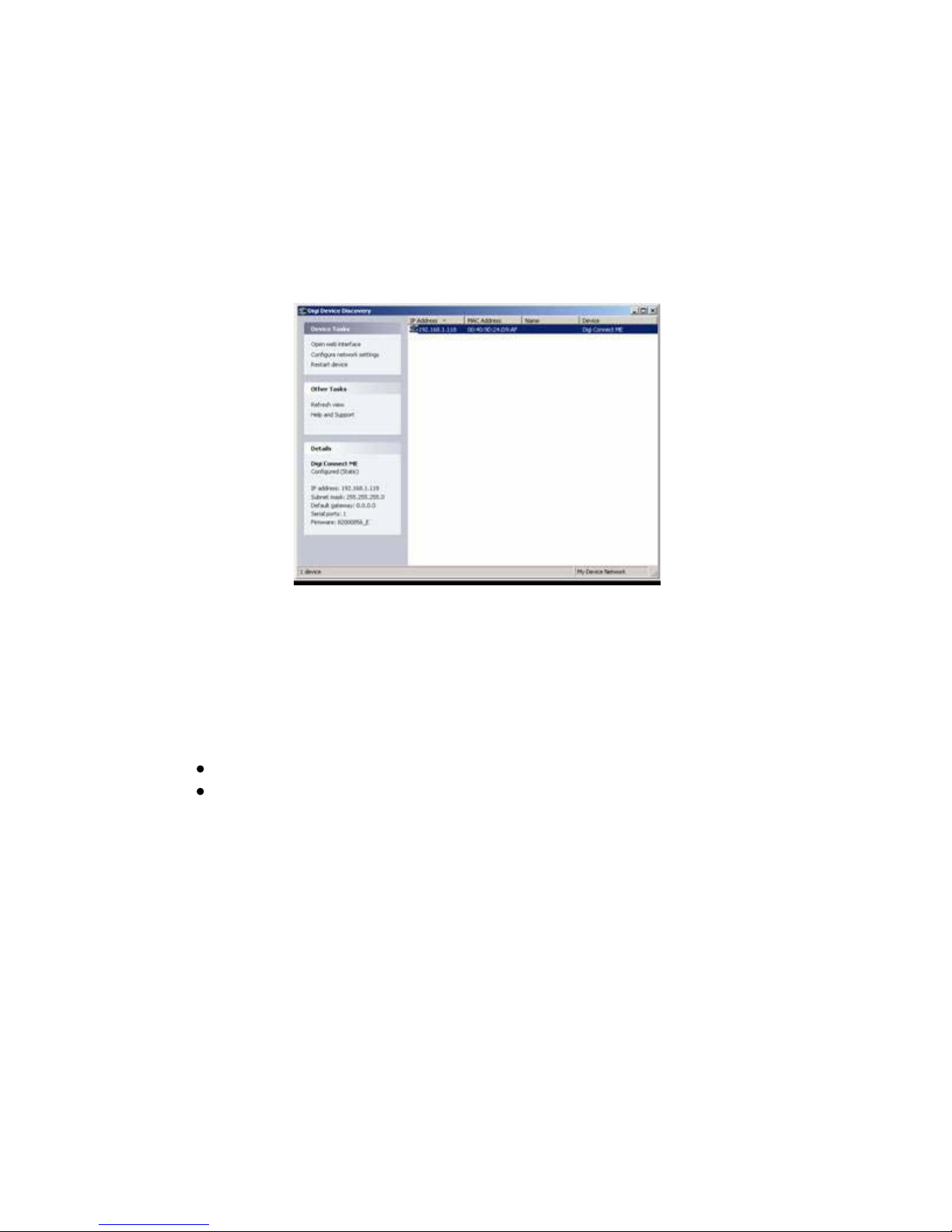
C-9
Connect, Digi Device Discovery”. When the utility opens, it scans the LAN
looking for Digi Ethernet modules. It may take a minute after plugging in or
powering the Ethernet module before the LAN negotiates the connection with the
Digi module. Hit “Refresh View” in the left column after a minute or so if the utility
fails to see the unit when you start it. In some situations it is possible that the
Windows Firewall will block the Digi Device Discovery from being able to see the
unit. It is advisable to turn the Windows Firewall off while performing these tasks.
When the utility sees the Digi device, it will display it in the list (Figure 1).
Figure 1: Digi Device Discovery utility displaying Digi module discovered on the
LAN.
From this point, a web interface can be opened, allowing access to configura-tion
options for the Digi module. If you are required to enter a username and
password, they are as follows:
Username: “root”
Password: “dbps”
If a static IP address is desired, this change can be made from the web interface.
Please note, however, that if the IP address is changed such that it is
incompatible with the LAN, all communication including access to the module’s
settings (including the IP address!) will no longer be possible over the LAN. If this
happens, a crossover cable must be used to access the Digi module’s settings
(again using Digi Device Discovery). Temporarily set the pc’s IP address to be
compatible with the Digi module’s IP address to get the pc and pulse generator to
‘see’ each other over the crossover cable.
Page 51

D-10
Appendix D - DT15 (Dual Trigger Option)
Mode: Disabled
Mode:
Triggered
Mode: Dual Trig
*
Threshold Level
Threshold
Level
Trigger Edge
Trigger Edge
Mode: Disabled
Mode:
Triggered
Mode: Dual Trig
DT15 Overview
This module option allows the “Gate” input to function as a second trigger input.
For consistency, the enabling menu for this option is located under the “Trig”
menu structure. Once the dual trigger mode is enabled, both the “Gate” and
“Trig” inputs can act as trigger inputs.
Adjustments for the “Gate” trigger input are located under the “Gate” menu
structure. The voltage threshold level and trigger edge for the “Gate” input can be
adjusted from this menu. The “Gate” trigger edge choice is only available when in
dual trigger mode.
Once dual trigger functionality is enabled on the unit, each channel can be
as-signed to either of the trigger inputs. The default trigger source for each
channel is the “Trig” input. The trigger source selection is accessed in the
secondary channel menus. To access this menu, first press the yellow “Func”
button followed by the channel of interest. Continue to press “Func” then the
channel button until the menu page with “Ch Gate:” and “TrigSrc:” appears. Use
the “Next” button to place the cursor on the “TrigSrc” line and use the up/down
arrows to change to the desired trigger source.
DT15 Menus
Trigger 1 Menu (TRIG key)
Enabling System Trigger
Enable the use of the TRIG input by the system timer as a trigger source.
Mode: Selects between disabling/enabling the trigger
mode(s).
Level: Sets the trigger threshold. Edge: Selects between
rising and falling edges as the trigger source when a
trigger mode is enabled.
Trigger 2 Menu (GATE key) *
Page 52
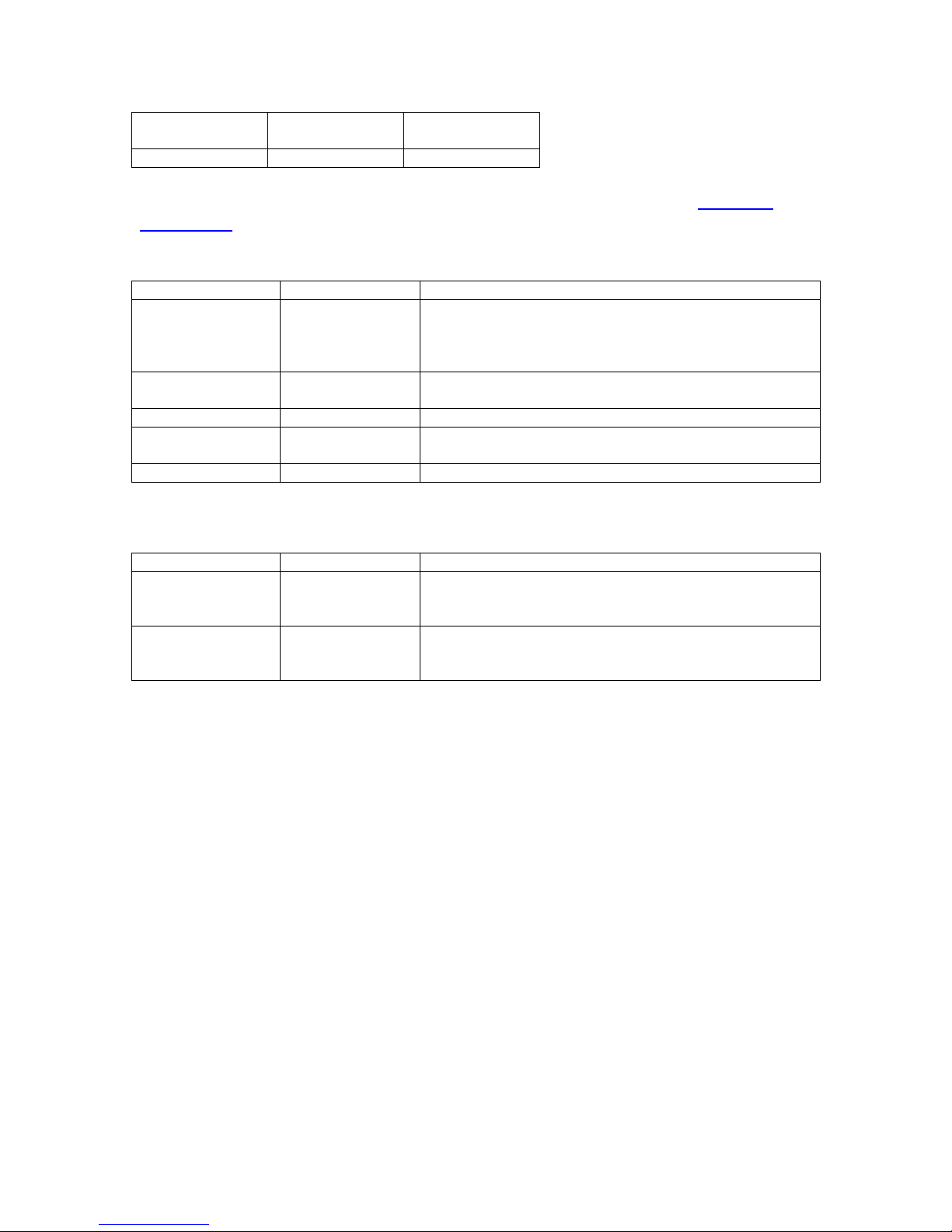
D-11
Threshold Level
Threshold
Level
Trigger Edge
Trigger Edge
Keyword
Parameter
Comments
:PULSe [0]
Subsystem. Contains commands to control the
output pulse generation. Commands without suffix
refer to the currently selected logical instrument.
See INSTrument subsystem.
:TRIGger
Subsystem. Contains commands to define the
Trigger function.
:MODe
DUAL
Sets the unit into dual trigger mode.
:PULSe[1/2/n]
Valid suffix range depends on the number of
channels (ChA = 1, ChB = 2, etc).
:CTRIGger
GATE/TRIG
Sets which input is assigned to the channel trigger.
Keyword
Command Name
Comments
*TTG
Trigger –
Trigger Input
Generates a software trigger pulse for the TRIG
input only. Operation is the same as receiving an
external trigger pulse on the Trigger input.
*GTG
Trigger – Gate
Input
Generates a software trigger pulse for the GATE
input only. Operation is the same as receiving an
external trigger pulse on the Gate input.
*Only enabled when TRIG mode is set to “Dual Trig”. Functions as Standard
Gate Menu when not in “Dual Trig” mode.
DT15 SCPI Command Summary
DT15 IEEE 488.2 Command Summary
Page 53

E-12
Appendix E - AT35 (35V Output Option)
AT35 Description
When the Adjustable Mode is enabled for this module, the outputs will provide an
adjustable output from 5 volts to 35 volts. The pulse width can be set over the
standard range of the unit, but the 35 volt output will self limit to approximately 4
µs with some droop. There is no change to TTL output mode functionality with
this module.
To maintain the highest possible rise time, care must be taken with cabling and
termination. Low capacitance cable and 50 ohm termination will provide the
fastest rise times without overshoot. Faster rise times can be achieved by
increasing the termination resistance, but some overshoot is likely to occur.
While the 35 volt output provides a fast, controlled rising edge, the pulse width
and falling edge are not tightly controlled. Also, when using the 35V mode, the
option will only function if the ‘Polarity’ is set for “Active High”.
AT35 Specifications
Through a 50 ohm load at 200 Hz
Output 5 V – 35 V
Setpoint Resolution 10 mV
Rise Time < 30 ns
Accuracy 500 mV
Max. Frequency (Internal & External) 4000 Hz
Page 54
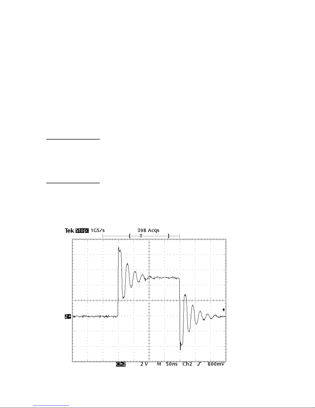
F-13
Appendix F - TZ50 (Impedance Matching
Output Module)
TZ50 Overview
This module option allows a user to have a 50 Ohm load on the output while
maintaining output amplitude of at least 4 Volts while in the TTL/CMOS mode. All
other functionality of the module is the same as the AT20 modules, including
output while using the Adjustable Mode Function of the channels.
TZ50 Specifications
TTL/CMOS Mode
Output Level 4.0 V typ into 50 Ohms
Rise Time 3 ns
Slew Rate 0.5 V/ns
Jitter - Channel to Channel 50 ps RMS
Adjustable Mode
Output Resolution 10 mV
Current 100 mA typ, 400 mA max (short pulses)
Slew Rate 0.1 V/ns
*Note: The TZ50 module has significant overshoot and ringing through high
impedance (see figure below).
Page 55
G-14
Appendix G - Increment Modes Option
MODE:
BurstIncr
MODE:
DCIncrement
#/On
#/Burst
#/Off
MODE:
BurstIncr
MODE:
DCIncrement
Cycles
T0 Period
T0 Period
Increment Overview
The System Increment modes are a pair of special modes, which allow the delay
and width of each channel to be incremented at the end of a burst of pulses.
Each channel is independent and each may be set with different initial values
and different values for the step size for both the delay and the pulse width.
There are two incrementing modes, Increment and DC Increment. In the
Incre-ment mode, each start command or external trigger produces a burst of
pulses. At the end of the burst the appropriate delays and pulse widths are
incremented and the instrument is armed for the next start command. In the DC
Increment (Duty Cycle) mode the output is starting as with the normal duty cycle
mode. At the end of each cycle the delays and pulse widths are incremented.
This contin-ues for the number of cycles defined by the Cycles parameter. The
modes are selected from the system mode menu. The step sizes are specified in
the channel menus.
Increment Menus
System Mode Menu 1 Extensions (FUNC + MODE key)
System Mode Menu 2 Extensions (FUNC + MODE key)
Setting System Increment Modes of Operation
The MODE menu sets the T0 system timer mode. The menu will show the extra
set parameters (Burst, On & Off) only when they are appropriate.
Mode: Selects the T0 mode: Continuous, Single Shot, Burst or Duty
Cycle mode.
Burst: Sets the number of pulses to be generated when in Burst
mode.
On: Sets the number of pulses to be generated during each on
cycle.
Page 56
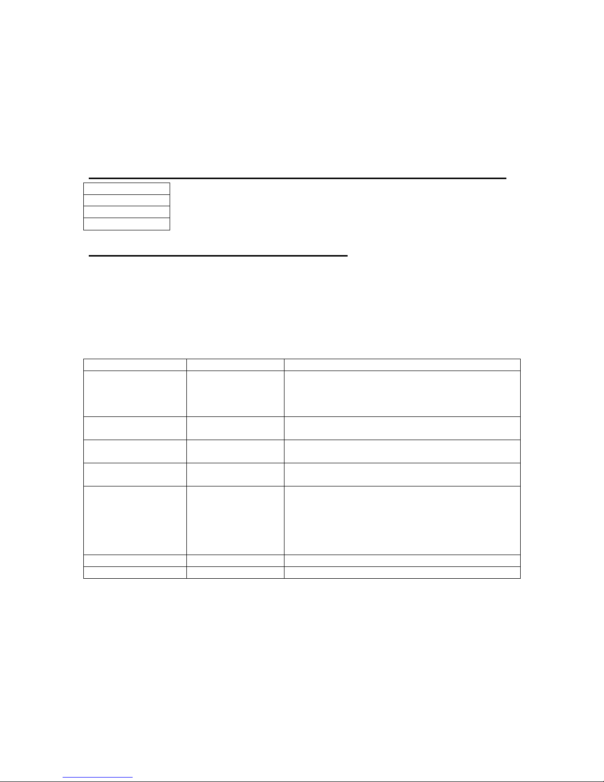
G-15
Off: Sets the number of pulses to skip each during off
Channel Enable
Increment Wid *
Increment Dly *
Keyword
Parameter
Comments
:PULSe[0]
Subsystem. Contains commands to control the
output pulse generation. Commands without
suffix refer to the currently selected logical
instrument. See INSTrument subsystem.
:MODe
BINCRement /
Sets the T0 mode. Added parameters for Burst
Increment and Duty Cycle Increment mode.
:CYCLe
<numeric value>
Sets the number of cycles to generate in Duty
Cycle Increment mode.
:IRESet
1
Resets the width and delay increment
parameters on all channels.
:PULSe[1/2/n]
Subsystem. Contains commands to control the
output pulse generation. Valid suffix range
depends on the number of channels (ChA-1,
ChB-2, etc . . .). Command without suffix refers
to the currently selected logical instrument. See
INSTrument’s subsystem.
:IWIDth
<numeric value>
Sets the pulse width increment step size.
:lDELay
<numeric value>
Sets the delay increment step size.
cycle when in the Duty Cycle mode.
Cycles: Sets the number o DC Increment Cycles to generate
before completion.
To: Sets the T0 period which determines the fundamental
output frequency of the unit.
Advanced Channel Menu Increment Extension (FUNC + channel key)
Setting the Channel Increment Parameters
To define a pulse requires two parameters: the delay to the active edge and the
width of the pulse.
IncW: Sets the channel pulse width.
IncD: Sets the channel delay until the active edge.
Increment SCPI Command Summary
Increment Initialization and Reset (FUNC + CLR)
Pressing the FUNC key then CLR initializes the increment parameters and resets
the delays and pulse widths to their initial conditions. This must be done after
setting all the step parameters, but before generating any pulses.
Increment Specifications
Width Step Size -1.00 s to 1.00 s
Width Minimum Step 10 ns (-10 ns)
Page 57

G-16
Width Step Resolution 250 ps
Width Incremented Range 10,000 s
Delay Step Size -100 ms to 100 ms
Delay Minimum Step 10 ns (-10 ns)
Delay Step Resolution 250 ps
Delay Incremented Range 10,000 s
*Note: Any increment value between -10ns and 10ns will disable the increment
function for that parameter.
Update Rate 10 µs + 30 µs per active channel (1 Ch
@ 25 kHz to 8 Ch @ 4 kHz)
Page 58

H-17
Appendix H - AT45 Option (45 Volt Output)
Channel Enable
Channel Enable
Output Type:
High Z
Output Type:
Low Z
Polarity
Output Level
Output Level
AT45 Option Overview
For channels with AT45 output option, the maximum frequency is limited to 100
kHz. The pulse width can be set over the standard range of the unit with both
active high and low outputs when set to high impedance mode. In low impedance
mode, the pulse width is limited to a maximum of 10s and the active high output
is no longer allowed. To maintain the highest possible rise time, care must be
taken with cabling and termination. Low capacitance cable and 50 ohm
termination will provide the fastest rise times without overshoot. The channel
menu structure for the AT45 module changes are described in the table below
(changes from standard outputs are in bold italics).
AT45 Protection Error Messages
When an AT45 module is present, the system performs self-checks to insure the
module is not damaged when attempting to over-drive.
Module Errors
If a channel on any AT45 module is over-driven, the channel will disable itself
and the system will indicate an error on the module. The error will not clear until
the user presses FUNC - PERIOD key sequence to clear the error, or power
cycles the instrument.
System Limit Error
The system will not allow the Lo Impedance enabled AT45 channels to exceed
150V total amplitude. If this situation occurs, the “Over-Driving Unit” error is
displayed and the currently adjusting amplitude is reduced to the 150V enabled
system limit.
Voltage Change Timing
The channels adjustable voltage changes very quickly when adjusting from a
lower voltage to a higher voltage but changes slowly when changing from a
higher voltage to a lower voltage. It takes approximately 30s to change from 45V
to 3.0V so caution must be taken when adjusting the voltage to a lower voltage
tolerant circuit.
AT45 Channel Menus
Channel Output Configuration Menu
Page 59
H-18
AT45 SCPI Command Extension Summary
Keyword
Parameter
Comments
:PULSe [1 / 2 / n]
Subsystem. Contains commands to control the
output pulse generation. Valid suffix range
depends on the number of channels (ChA = 1,
ChB = 2, etc). Command without suffix refers to
the currently selected logical instrument. See
INSTrument subsystem.
:OUTPut
Subsystem. Contains command to control
output mode.
:MODe
HIZ / LOZ
Selects output Amplitude mode: High
Impedance or Low Impedance
:AMP
4 V – 45 V
Sets adjustable output level.
:MERRor
1
Command clears the last module error to allow
the unit to generate pulses again. Query
returns the last displayed error.
AT45 Specifications
Amplitude 4 V – 45 V
Resolution 20 mV
Accuracy +/-1.5%
Rise Time < 2 ns Typical 10%-90% (Low Z)
< 9 ns Typical 10%-90% (High Z)
Fall Time < 9 ns Typical 90%-10% (Low Z)
< 7 ns Typical 90%-10% (High Z)
Frequency (Internal & External) DC – 100 kHz
Overshoot <35% Typical Allowed for Fast
Rise Time
Polarity - High Z (>10k) Active High or Active Low
Polarity - Low Z (50 Ohms) Active High Only
Pulse Width - High Z (>10k) 10 ns to DC
Pulse Width - Low Z (50 Ohms) 10 ns to 10 s
Current (maximum) 35 mA (High Z @10 ms width)
900 mA (Low Z @ 10 ms width)
Page 60
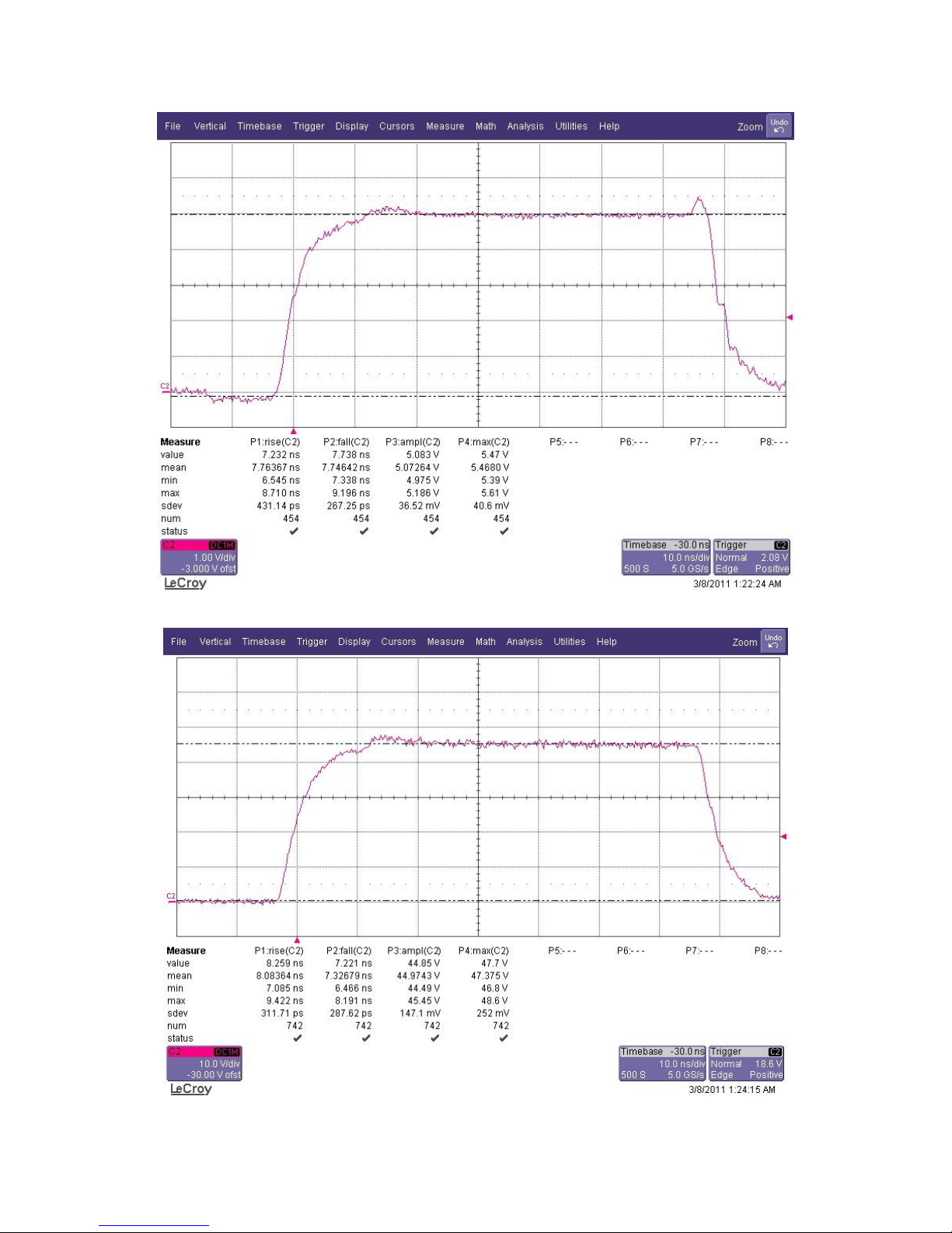
H-19
Figure 1 (High Z 5V)
Figure 2 (High Z 45V)
Page 61
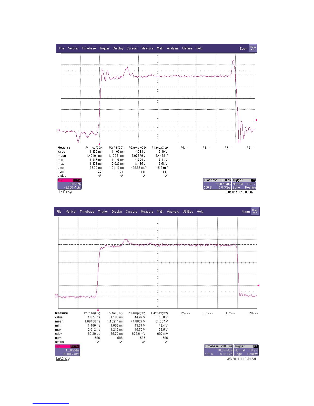
H-20
Figure 3 (Low Z 5V)
Figure 4 (Low Z 45V)
Page 62
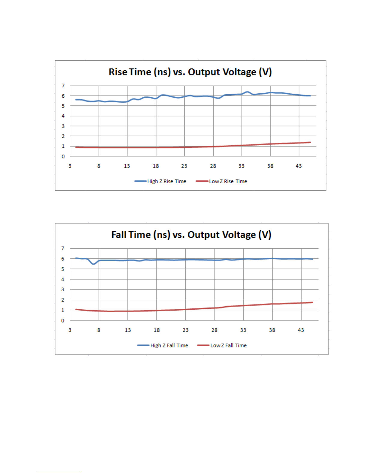
H-21
Rise time and overshoot are tuned for best response at low impedance (low Z)
Figure 5 (Rise Time versus Output Voltage)
Figure 6 (Fall Time versus Output Voltage)
Page 63
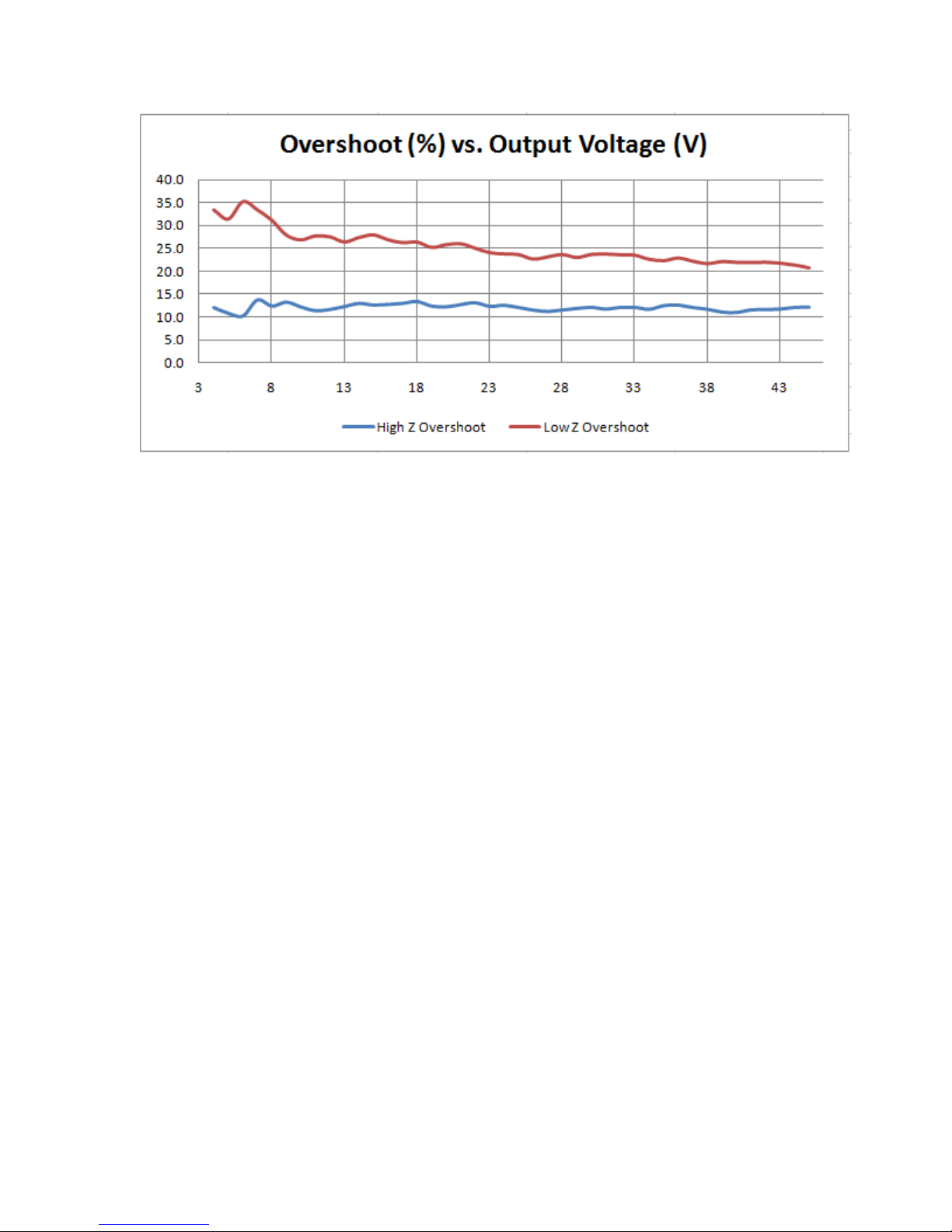
H-22
Figure 7 (Overshoot Versus Output Voltage)
 Loading...