

Page 1
Operating Instructions
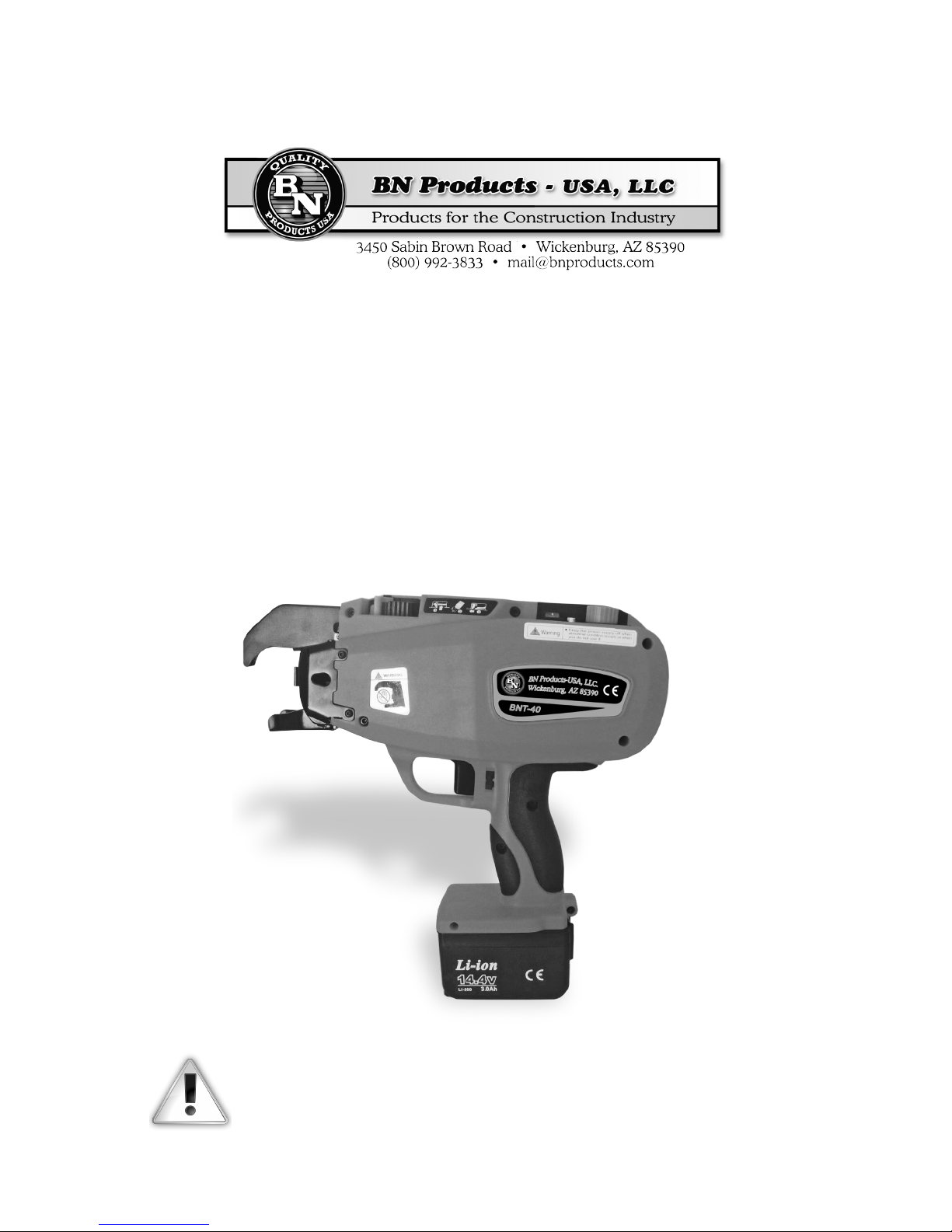
BNT-40 Automatic Rebar Tying Machine
is Tool Has
Passed ISO9001 International
Quality System Certication
e charger has passed ETL Certication
Please read this manual carefully before using this machine to
make sure you are familiar with all safety and warning instructions.
Page | 1
Page 2

Please read this manual carefully before using this machine to
make sure you are familiar with all safety and warning instructions.
e BN-40 is a hand-held battery operated tool. In this manual you will learn that this machine
consists of four parts: the machine body, special wire coil, battery box and a charger. e tool is
designed to be used for the fast tying of rebar or steel used in construction sites for the building
trades. Due to its speed, convenience and safety, this machine can save a great deal of valuable labor and material resources. In addition, the parts and components as well as advanced production
technologies are made from well-known manufacturers both here and abroad. is machine was
developed as an economical and practical tying machine with many international patents.
--------------------------------------------------------------------------------
Table of Contents
3 | Machine Call-Outs
4 | Safety
5 | Safety Locks
5 | Product Specications and Technical Parameters
6 | Battery and Charger Usage
6 | Machine Operation and Methods
7 | Replacement of Gears
7 | Care and Maintenance
8 | Common Faults and Removal Methods
--------------------------------------------------------------------------------
Page | 2
Page 3
OPERATION INSTRUCTION
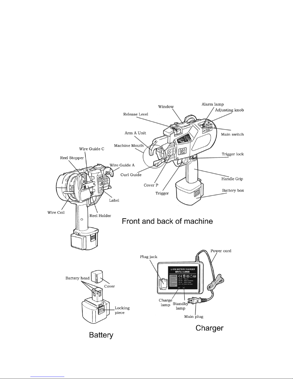
Machine Call-Outs
Page | 3
Page 4
Safety
is machine is a high-performance battery operated tool.
Failure to follow the warnings and instructions may result in
an electric shock, re or serious injuries.
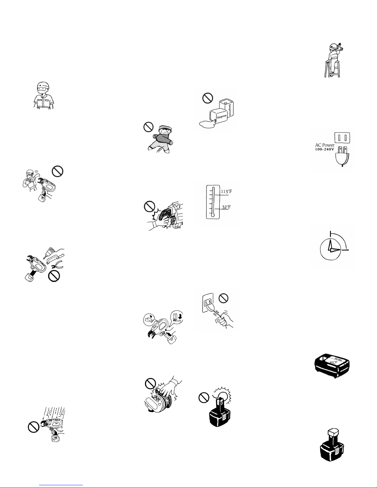
• Always operate the tool with personal
protection equipment (safety helmet and
eye protection, etc...). Using the appropriate safety equipment at all times will avoid
body injury.
• Keep children and bystandards away
while operating this tool. Distractions may
cause serious accidents.
• Do not aim the tool at
those standing around your work area. Serious accidents can happen if you mishandle this tool.
• Do not place your hand
or position the machine mouth (between
arm A and the curl guide) near the body.
is will cause serious injury.
• Do not attempt to dismantle, modify or
perform any major maintenance on this
tool. Any modication may result in a deteriorations of the tool’s performance and
may cause serious injury and void any warranty.
• Make sure that the electric switch is in
the o position when the tool is not being
used or when abnormalities occur. When
changing or adjusting the wire coil, or
when changing the battery pack, make sure
to turn o the main power switch and lock
the trigger.
• Do not place ngers or hands in the wire
coil area. is may result in distortion of
the coil and may cause injury to you.
• Do not operate this tool
in the rain or areas where
moisture is present. is may result in
electrical shock or accident.
• Stay particularly alert while working in
a lo area. Do not operate any power tool
under the inuence of drugs, alcohol, or
medication. A moment of inattention may
result in serious injury to you or someone
near you.
• Do not operate this tool in a hazardous
area containing ammable liquid, gas or
powders which may ignite and cause a re.
• e charger has been de-
signed to use standard AC
power (100-240V ~ 50-60Hz). Do no recharge the battery using a generator power
supply as this will cause the charger to malfunction.
• Our batteries charge best when the ambi-
ent temperature is between 32°F and 113°F.
Super-cooling or over-heating environ-
ments are not suitable for charging.
• Continuous use of the
charger is not advised as this will shorten
the life span of the battery and the performance of the charger itself. When not in the
charging mode the power supply must be
turned o.
• Please do not carry the charger by the
cord. Do not pull out the power cord from
the wall socket with a strong force, this will
damage the cord and break the wires or
cause a short circuit. A damaged cord must
be repaired or replaced immediately.
• Use only the specied charger that came
with your machine. Using a unauthorized
charger may result in damage to the battery
components and possible explosion.
• Avoid battery terminal
contact with other metal objects. Trying to
recharge the battery with an external wire
could result in a short circuit of the battery.
• Do not throw away the
protective battery cap. Use it to cover the
terminal when not in use.
Page | 4
Page 5
Safety Locks
Make sure that all safety features are operational before using any power tool.
DO NOT OPERATE THE TOOL IF THE SAFETY LOCKS
ARE NOT FUNCTIONAL.
is tool is equipped with the following safety devices:
• e Main Switch: Please turn the main
switch on the power supply o when not in
operation.
• e Trigger Lock: Always
turn the trigger lock to
the o position when not in use or when
changing the wire coil.
Tool Technical Parameters
Model BNT-40
Dimensions (in.) 11.22 x 3.93 x11.65
Weight (lbs) 4.85 Incl Battery
Voltage (V) 14.4
Max Tying Diameter (in.) 1.57
Wire Technical Parameters
Type NY80
Dimeter (in.) ø0.03
Material Q195
Length (in.) 3937(approx)
Product Specications and Technical Parameters
(mm)
Page | 5
Page 6
be bent or curved).
Battery and Charger Usage
• Before inserting or removing the battery from this tool,
please set the main switch to the o position.
• To avoid a short circuit to the battery, always use the battery terminal cover when it is not in use with the tool.
• When placing the battery into the tool, press the battery
lock before placing it into the battery holder. When removing the battery, press the battery lock button before pulling
it out of the battery holder.
• Use 100-240V ~ 50-69Hz AC power supply for the charger.
Fully insert the battery into the charger slot and it will begin
to charge automatically as indicated by the charging light.
It will take approximately 74 minutes to fully complete the
battery charge.
• It is recommended to charge the battery between 32°F and
113°F. Do not charge in extreme cold or hot environments.
Machine Operation and Methods
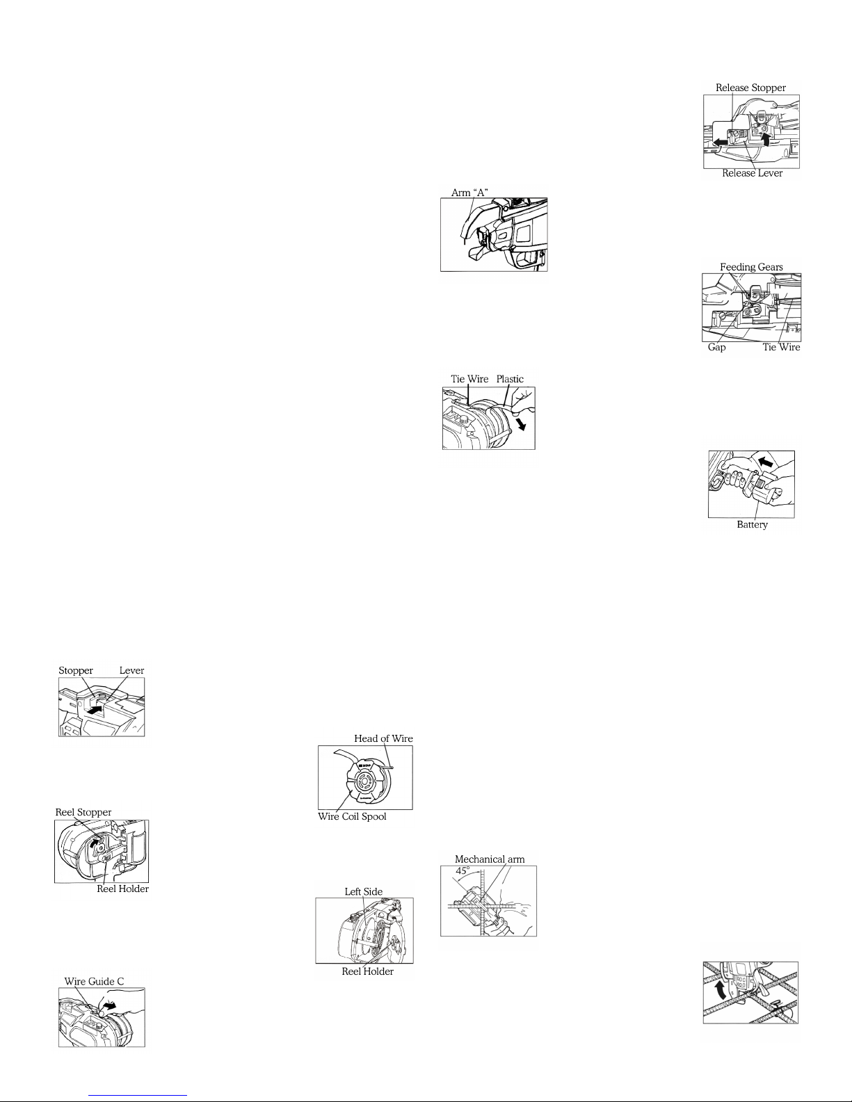
Before inserting and removing the wire coil spool turn the
main power switch to the o position, lock the trigger switch
and remove the battery.
Installing the wire coil spool. Please only use matching
wire without rust in this tool.
e wire must pass through the wire
guide “C” in between the two feeding
gears until it reaches the end gap. en
push the wire until it reaches the machine
arm.
Keep pushing the wire until it reaches
the arm “A” unit.
Release the release
stopper and conrm
the release lever has
returned to its original position. (Note:
the wire coil must be clamped the gap of
the feeding gears).
Remove the rest of the remaining adhesive tape from the wire spool.
Install the battery into
the machine, when
you hear a locking
sound the battery has been installed correctly. (Note: make sure that the main
power switch is in the o position and
that the trigger is locked before installing the battery).
Turn on the main power switch. e machine is now ready
for use.
How to remove the wire coil spool
Only use original wire coil. Using nonstandard wire or spool could cause the tool
to malfunction.
Remove part of the adhesive tape and cut about 2 inches of wire
from the coil.
Push the reel stopper to
release the reel stay and open the gate at
the same time.
Install the wire coil with the le side facing the tool. Lock the opening by closing
the reel holder.
Insert the wire into the
wire guide “C” (Note: the wire must not
Turn o the main power switch, lock the trigger and remove
the battery.
Press the release lever and conrm that it is caught in the
open position.
Remove the plastic wire coil spool.
e Tying Procedure
Unlock the trigger lock. Keep the mechanical arm on the rebars to be tied with
a 45° angle at a vertical position to the
rebars.
Press the trigger and the
tool will tie automatically.
Remove the tool when the tying is com-
Page | 6
Page 7
plete.
Do not press the trigger when the mechanical arm is not on the rebar surface.
(Note: if this should happen turn o the
maching, position the trigger lock to the
“o” position and remove the trapped
wire with a pair of pliers inside the me-
chanical mouth).
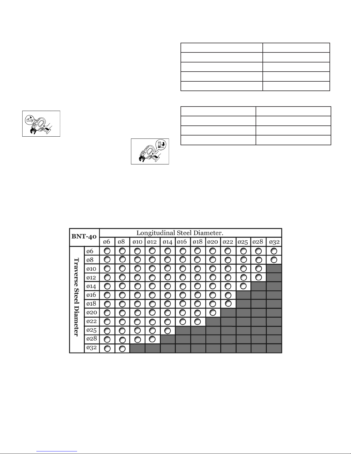
Adjust the tie tightness. ere are 5 tightness levels that can
be adjusted with the “adjusting dial”.
Replacement of Gears
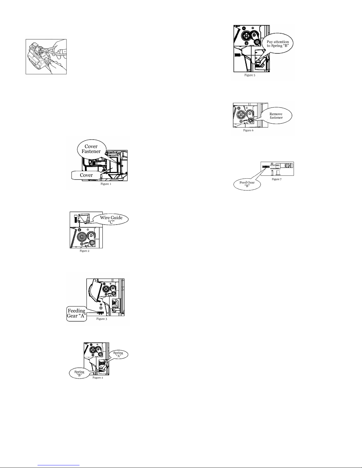
• Be careful not the drop the smaller Spring “B” at the other end of the release lever when you take out Spring “A” as
shown above.
• Remove the hex screws of the release lever from the plate
and take out the release lever in the direction of the arrow
as shown above.
• Remove the screws that fasten the plastic housing over the
motor as show above.
• Remove the wire guide “C” which is fastened on the plate
as shown above.
• Use a pair of pliers to remove the E-ring and washer xed
on the feed gear as shown above.
• Aer you remove the release lever you can remove the E-
rings with pliers and the feeding gears “B” and then replace
them as shown above.
NOTE:
Aer you nish replacing the gears all of the tool parts must
be reassembled in order.
• First install the release lever and fasten it.
• Fit Spring “A” at the end of the release lever
• Install the feeding gears, washer and E-ring in sequence
• Fix wire guide “C” on to the plate
• Finally attach the plastic cover with screws.
Care and Maintenance
• Please do a daily inspection prior to using this tool
• Please maintain this electric tool carefully, making sure
that the adjustments are correct and that it has been stored
properly.
• With a pair of pliers remove Spring “A” at the end of the
release lever as shown above.
• Inspect the tool for damage and cracks in the housing and
that the power supply is in good working order.
• Make sure theat the battery charger is the one that came
with your machine. Using another charger could cause
damage to the battery and/or charger and could even cause
a re.
Page | 7
Page 8

• Improper use of the battery could cause it to leak. If this
happens it will need to be replaced and properly recycled.
Please do not touch any leaking material from this battery.
• In the event that this tool malfunctions or drops in performance you can call our Customer Service Repair Center
(800) 992-3833 or send us a note to [email protected]
If you come in contact with the battery liquid ush with
clean water and seek medical attention immediately.
BN Products-USA
• When not in use, store this tool carefully in the supplied
case. It can be washed with a so cloth and soapsuds aer
you nish work. Do not use petrol chemicals or alcohol to
(800) 992-3833 • [email protected]
3450 Sabin Brown Road
Wickenburg, AZ 85390
clean this tool.
Common Faults
is tool alerts you to the following fault conditions by means of a warning sound and warning light. If the problem is not
solved please contact our maintenance support department: (800) 992-3833.
Common Faults
e machine does not
work aer
putting in a new wire
spool.
e wire does not feed
correctly
Irregular binding and
wire stepping out of
the curl guide
Failure to cut the wire
aer binding
Tying knot is loose
Tying knot is not correct
Warning
Sound
None O Inspect the battery
Beep---- On- Conrm that the battery
Beep,
Beep,Beep
Beep, Beep,
Beep, Beep...
Beep, Beep On O On O
Beep, Beep,
Beep
Beep, Beep,
Beep, Beep...
None On- Alarm when pressing the
None On- Check if the wire hits the
None On- Check to see if the cutting
None On- Check the operation
None On- Check the tying strength e tying force is
Indicator
Light
On O On O
On o...
On O On O
On o...
On o...
On O On O
On o...
On O On O
On o...
Items To Inspect Possible Cause Actions
Oxidation or there
terminal
is charged
Check wire guide “A” to
see if there is stray wire in
the guide
Check the curl guide to
see if there is a stray wire
caught in the tool
Check the curl guide e curl guide is
Check the diameter of the
rebars
Check the tightness of the
wire coil
trigger- No alarm when
released
rebar when tying
mechanism is working
correctly
instruction
is dirt on the electrodes
Low power in the
battery
e head of the wire
was caught in the
guide
Tying strength may
be to strong
open
e diameter of the
rebar exceeds chart
e wire is too tight
on the coil
Overheated motor
from constant use
e wire hitting the
rebar will stop the
action
ere may be a stray
piece of wire in the
cutting mechanism
Wrong operation Please read the
too great
Use a dry cloth to
wipe the surfaces
Recharge the battery
Using a pair of pliers
remove the wire
Adjust the tying
force and remove the
caught wire
Close the curl guide
Use the proper diameter rebars
Clear the winded wire
Let the motor cool
down
Pay attention so that
the wire does not hit
the rebar
Clean the cutting
mechanism
operation manual
Adjust to the proper
tying force
Page | 8
 Loading...