

Page 1
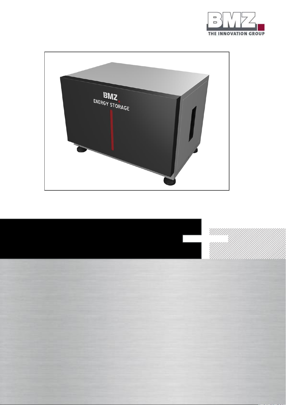
OPERATING MANUAL ESS 7.0
Page 2

Version 1.1
Original operating manual
Page 3

Copyrights
Version 08/2016
Copyright © BMZ GmbH
Subject to technical modifications that are required for advancements.
This operating manual or parts thereof may not be reproduced in any format (photocopy, micro film or
other methods) or used, duplicated or processed with the help of electronic systems without a written
consent of BMZ GmbH. In case of violations of these regulations, we reserve the right to claim damage
compensation.
BMZ GmbH
Am Sportplatz 30
63768 Karlstein am Main
Germany
Telephone +49 (0)6188 99 56 0
Service +49 (0)6188 99 56 9830
Fax +49(0)6188 99 56 900
Website: http://www.bmz-gmbh.de
Email: [email protected]
Page 4

About this manual
General
A qualified electrician must carry out installation, commissioning and maintenance. Please read this
operating manual carefully to ensure a fault-free operation of the BMZ ESS 7.0 battery storage system.
Please store this operating manual such that it is accessible to all persons who work on the BMZ ESS 7.0
system.
Scope
This manual is intended for all products of the BMZ ESS 7.0 series.
Differentiation between an operating company and operator
The end consumer is referred to as an operating company in this manual. The system is installed and put
into operation for this operating company.
A person, who works on the system or its controllers, is referred to as an operator in this manual. This
person must be a qualified electrician authorised by BMZ GmbH.
Liability exclusion
BMZ GmbH does not bear any liability for damage resulting from unintended usage and non-adherence to
this manual. This includes personal injuries, material damage, damage to the product as well as
consequential damage, repair damage and other handling of the product by non-qualified electricians. This
liability limitation is applicable even when non-original spare parts are used.
Carrying out arbitrary changes or technical modifications in the product is strictly prohibited.
A liability for profits lost or other costs and financial losses is ruled out.
Page 5

Table of contents
About this manual ............................................................................................. 4
Table of contents ............................................................................................... 5
List of figures ................................................................................................... 10
1 Safety ................................................................................................................... 13
1.1 Classification of warnings and intended use ....................................... 14
1.1.1 Warnings in the operating manual .......................................................................... 14
1.1.2 Intended use ............................................................................................................ 15
1.2 Safety instructions to be followed ......................................................... 16
1.2.1 General safety instructions ..................................................................................... 16
1.2.2 Safety instruction when working with the tool ....................................................... 18
1.2.3 Safety instructions for transport and installation ................................................... 19
1.2.4 Safety instructions for operation ............................................................................ 21
1.2.5 Safety instructions for cleaning ............................................................................... 23
1.2.6 Safety instructions for maintenance and dismantling ............................................ 24
1.2.7 Safety instructions for battery interiors .................................................................. 26
1.2.8 Safety instructions for fire prevention .................................................................... 28
1.2.9 Explosion protection ............................................................................................... 29
1.2.10 Residual risks ........................................................................................................... 29
1.3 Data and safety devices of the battery storage system ....................... 30
1.3.1 General hazard instructions and pictograms .......................................................... 30
1.3.2 Installed safety systems .......................................................................................... 32
1.3.3 Safety checks ........................................................................................................... 33
2 Function, delivery scope and technical key variables ..................................... 34
2.1 Function .................................................................................................. 34
2.2 Delivery scope ........................................................................................ 34
2.3 System overview .................................................................................... 35
Page 6

2.4 Rating plates and warning stickers ....................................................... 39
2.5 Technical key variables .......................................................................... 42
3 Transport ............................................................................................................. 43
3.1 Safety instructions for transport ........................................................... 43
3.2 Transporting the battery storage system ............................................. 43
4 Installation, assembly and commissioning for the first time .......................... 49
4.1 Installation site requirements ................................................................ 49
4.2 Filling the warranty card ........................................................................ 51
4.3 Filling the installation check list ............................................................ 51
4.4 Installation of the battery storage system ............................................ 52
4.5 Preparing the electrical connections for the single mode .................. 54
4.5.1 Checking the connections ....................................................................................... 57
4.5.2 Switching the battery storage system on and off .................................................. 58
4.5.3 Configuring the parameters of the inverter ............................................................ 60
4.6 Preparing the electrical connections for the parallel mode ................. 61
4.7 Connection concept of multiple BMZ ESS 7.0 batteries with one or more
battery inverters ..................................................................................... 62
4.7.1 Communication ....................................................................................................... 62
4.7.2 Output contact ........................................................................................................ 64
4.7.3 Laying the power cable ........................................................................................... 68
4.8 Configuration of the ESS parallel mode................................................ 69
4.8.1 1-phase operation of a SMA Sunny Island inverter on 1 ESS battery ..................... 69
4.8.2 1-phase operation of a SMA Sunny Island inverter on 2 ESS batteries ................... 69
4.8.3 1-phase operation of a SMA Sunny Island inverter on 3 ESS batteries ................... 70
4.8.4 3-phase operation of a SMA Sunny Island inverter on 3 ESS batteries ................... 71
4.8.5 3-phase operation of a SMA Sunny Island inverter on 4 ESS batteries ................... 72
4.8.6 3-phase operation of a SMA Sunny Island inverter on 5 ESS batteries ................... 73
4.8.7 3-phase operation of a SMA Sunny Island inverter on 6 ESS batteries ................... 74
4.9 Configuration of the ESS battery........................................................... 75
Page 7

4.9.1 System structure ..................................................................................................... 75
4.9.2 Addressing the batteries ......................................................................................... 75
4.10 Definition of the battery mode during commissioning and parameter
configuration .......................................................................................... 75
4.10.1 Single: ...................................................................................................................... 75
4.10.2 Master: .................................................................................................................... 75
4.10.3 Slave: ....................................................................................................................... 76
4.11 Work step sequence to configure the parameters of batteries ........... 77
4.12 Work step sequence to commission the batteries ............................... 78
4.13 Configuration of firmware for parallel mode........................................ 79
4.13.1 Setting the master battery mode ........................................................................... 79
4.13.2 Setting the master battery address ......................................................................... 80
4.13.3 Setting the slave battery mode ............................................................................... 81
4.13.4 Setting the slave battery address ............................................................................ 82
4.14 Commissioning the parallel connection of multiple batteries ............. 83
4.14.1 Switch-on sequence ................................................................................................ 83
4.14.2 Stand-by mode of a slave battery: .......................................................................... 83
4.14.3 Switch-on criterion of the slave battery: ................................................................. 83
4.14.4 Example 1: ............................................................................................................... 84
4.14.5 Example 2: ............................................................................................................... 84
4.14.6 Example 3: ............................................................................................................... 85
4.15 Checking the parallel connection of multiple batteries ...................... 86
4.15.1 Check the number of connected (detected) batteries ............................................ 86
4.15.2 Check the number of batteries for which the main relay is closed......................... 87
4.16 Adding new batteries ............................................................................. 87
4.17 Checking the connections of parallel battery systems ........................ 88
4.17.1 Switching the battery storage system on and off ................................................... 88
4.17.1 Configuring the parameters of the inverter ............................................................ 90
Page 8

4.18 Recommended parameters of the SMA Sunny Island inverter at the time
of installation: ......................................................................................... 91
4.18.1 On-grid application .................................................................................................. 91
4.18.2 Off-grid application ................................................................................................. 93
5 Operation and service software ......................................................................... 94
5.1 Pilot lamps (LED) .................................................................................... 94
5.1.1 LED indicators on the battery module .................................................................... 94
5.1.2 Charging status indicator ......................................................................................... 95
5.2 Connection of the notebook for servicing ............................................ 95
5.2.1 USB port .................................................................................................................. 95
5.2.2 Service software ...................................................................................................... 98
6 Fault/damage event ............................................................................................. 99
6.1 Fault indicators ....................................................................................... 99
6.1.1 Fault indicators of pilot lamps ................................................................................. 99
6.2 Actions to be taken in case of a damage ............................................ 100
6.2.1 First aid measures ................................................................................................. 100
7 Service and maintenance activities ................................................................. 102
7.1 Complaint handling .............................................................................. 103
8 Warranty conditions ......................................................................................... 104
8.1 General instructions ............................................................................. 104
8.2 Guarantee .............................................................................................. 104
8.3 Warranty service ................................................................................... 105
8.4 Warranty exclusion .............................................................................. 106
8.5 Warranty limitation ............................................................................... 106
8.6 Warranty time without KfW subsidy .................................................... 106
8.7 Warranty time with KfW subsidy (optional service by BMZ GmbH) .. 107
8.8 Area of applicability of warranty ......................................................... 107
8.9 Claiming for damages/warrantor ......................................................... 107
8.10 Concluding provisions ......................................................................... 107
Page 9

9 Dismantling and disposal ................................................................................. 108
9.1.1 Disposal of the battery storage system ................................................................. 108
10 Annexe ............................................................................................................... 109
10.1 Declaration of conformity .................................................................... 110
10.2 Warranty card ....................................................................................... 111
10.3 Installation check list ........................................................................... 112
Page 10

List of figures
Table 1-1 Hazard instructions, pictograms .............................................................................. 31
Figure 1-2: battery storage system, side view of NH1 isolator ............................................... 32
Table 2-1: delivery scope ......................................................................................................... 34
Figure 2-2: battery storage system, front view ....................................................................... 35
Figure 2-3: battery storage system, side view ......................................................................... 36
Figure 2-4: battery storage system, side view ......................................................................... 37
Figure 2-5: battery storage system, rear view ......................................................................... 38
Figure 2-6: battery storage system, rear side .......................................................................... 39
Figure 2-7: rating plate ............................................................................................................ 40
Table 2-8: rating plate.............................................................................................................. 40
Figure 2-9: battery storage system, recycling symbol ............................................................. 41
Figure 2-10: recycling symbol .................................................................................................. 41
Table 2-11: overview of technical specifications ..................................................................... 42
Figure 3-1: seal position........................................................................................................... 44
Figure 3-2: seal position........................................................................................................... 45
Figure 3-3: transporting with the sack truck ........................................................................... 48
Figure 4-1 : requirements for the installation site, distance of the ESS from walls, top view 50
Figure 4-2 : requirements for the installation site, distance of the ESS from walls, side view50
Figure 4-3: representation of the pulled current isolator ....................................................... 52
Figure 4-4: inverter, connection area for battery lines ........................................................... 54
Figure 4-5: sample representation of the connection of plus and minus power cables with
the SMA Sunny Island inverter ......................................................................................... 55
Figure 4-6: representation of external connections of the battery system, CAN ................... 55
Figure 4-7: battery storage system, side view of the opened housing ................................... 56
Figure 4-8: representation of the correctly inserted fuses ....................................................... 56
Figure 4-9: battery storage system, side view ......................................................................... 57
Page 11

Figure 4-10: communication cabling, ESS parallel connection ................................................ 63
Figure 4-11: RJ45 Y-adapter (even RJ45 T-connector) ............................................................. 63
Figure 4-12: pin assignment of RJ45 Y-adapter (T-connector) ................................................ 64
Figure 4-13: output cable of BAT Breaker Box ........................................................................ 64
Figure 4-14: BAT BREAKER Box of Enwitec (example for 6 batteries and 3 inverters) with a
closed housing .................................................................................................................. 65
Figure 4-15: BAT BREAKER Box of Enwitec (example for 6 batteries and 3 inverters) with an
open housing .................................................................................................................... 66
Figure 4-16: battery storage system, side view, power isolator pulled .................................. 67
Figure 4-17: cable lengths of the ESS system .......................................................................... 68
Figure 4-18 : 1-phase operation on 1 ESS battery ................................................................... 69
Figure 4-19: 1-phase operation on 2 ESS batteries ................................................................. 69
Figure 4-20: 1-phase operation on 3 ESS batteries ................................................................. 70
Figure 4-21: 3-phase operation on 3 ESS batteries ................................................................. 71
Figure 4-22: 3-phase operation on 4 ESS batteries ................................................................. 72
Figure 4-23: 3-phase operation on 5 ESS batteries ................................................................. 73
Figure 4-24: 3-phase operation on 6 ESS batteries ................................................................. 74
Figure 4-25: representation of the BMZ ESS service tool ........................................................ 75
Figure 4-26: representation of the work sequence to configure the parameters of a BMZ ESS
battery .............................................................................................................................. 77
Figure 4-27: representation of the work sequence to commission a BMZ ESS battery .......... 78
Figure 4-28: file structure of the BMZ ESS service tool ........................................................... 79
Figure 4-29: representation of configuration of the parameters of a BMZ ESS battery ......... 79
Figure 4-30: representation of configuration of the parameters of a BMZ ESS battery ......... 80
Figure 4-31: representation of configuration of the parameters of a BMZ ESS battery ......... 81
Figure 4-32: representation of configuration of the parameters of a BMZ ESS battery ......... 82
Figure 4-33: block circuit diagram of the BMZ ESS slave battery ............................................ 83
Figure 4-34: representation of example 1, different SOC of BMZ ESS batteries connected in
parallel .............................................................................................................................. 84
Page 12

Figure 4-35: representation of example 2, different SOC of BMZ ESS batteries connected in
parallel .............................................................................................................................. 85
Figure 4-36: representation of example 3, different SOC of BMZ ESS batteries connected in
parallel .............................................................................................................................. 85
Figure 4-37: check the number of BMZ ESS batteries connected in parallel .......................... 86
Figure 4-38: check the number of BMZ ESS batteries connected in parallel .......................... 87
Figure 4-39: SMA on-grid parameters ..................................................................................... 92
Figure 4-40: SMA off-grid parameters ..................................................................................... 93
Figure 5-1: pilot lamps table (LED) .......................................................................................... 94
Figure 5-2: side view of BMZ ESS, service flap ......................................................................... 95
Figure 5-3: push button with LEDs........................................................................................... 95
Figure 5-4: USB communication .............................................................................................. 96
Figure 5-5: USB port of BMZ ESS battery, inner side of housing ............................................. 96
Figure 5-6: push button and LEDs ............................................................................................ 97
Table 8-1: warranty service ................................................................................................... 105
Figure 10-1: EC Declaration of Conformity ............................................................................ 110
Figure 10-2: warranty card .................................................................................................... 111
Figure 10-3: installation check list ......................................................................................... 112
Figure 10-4: installation check list, part 2 .............................................................................. 113
Page 13

Safety
Version 1.0
Page 13 of 113
1 Safety
Target group
This section is aimed at all persons, including technical personnel, commissioning and shutdown personnel
as well as personnel who work on the battery storage system.
Background
Safety has utmost priority.
Use all aids provided to you along with the measures and processes listed in this section to ensure a safe
operation. Get a detailed information about all safety aspects.
You should be aware of the fact that hazardous situations may always arise when handling battery storage
systems.
Furthermore, the use of a battery storage is associated with the residual risks under the following
circumstances:
Installation and maintenance activities are not carried out properly.
Safety instructions given in this manual are not followed.
Page 14
Safety
Version 1.0
Page 14 of 113
DANGER
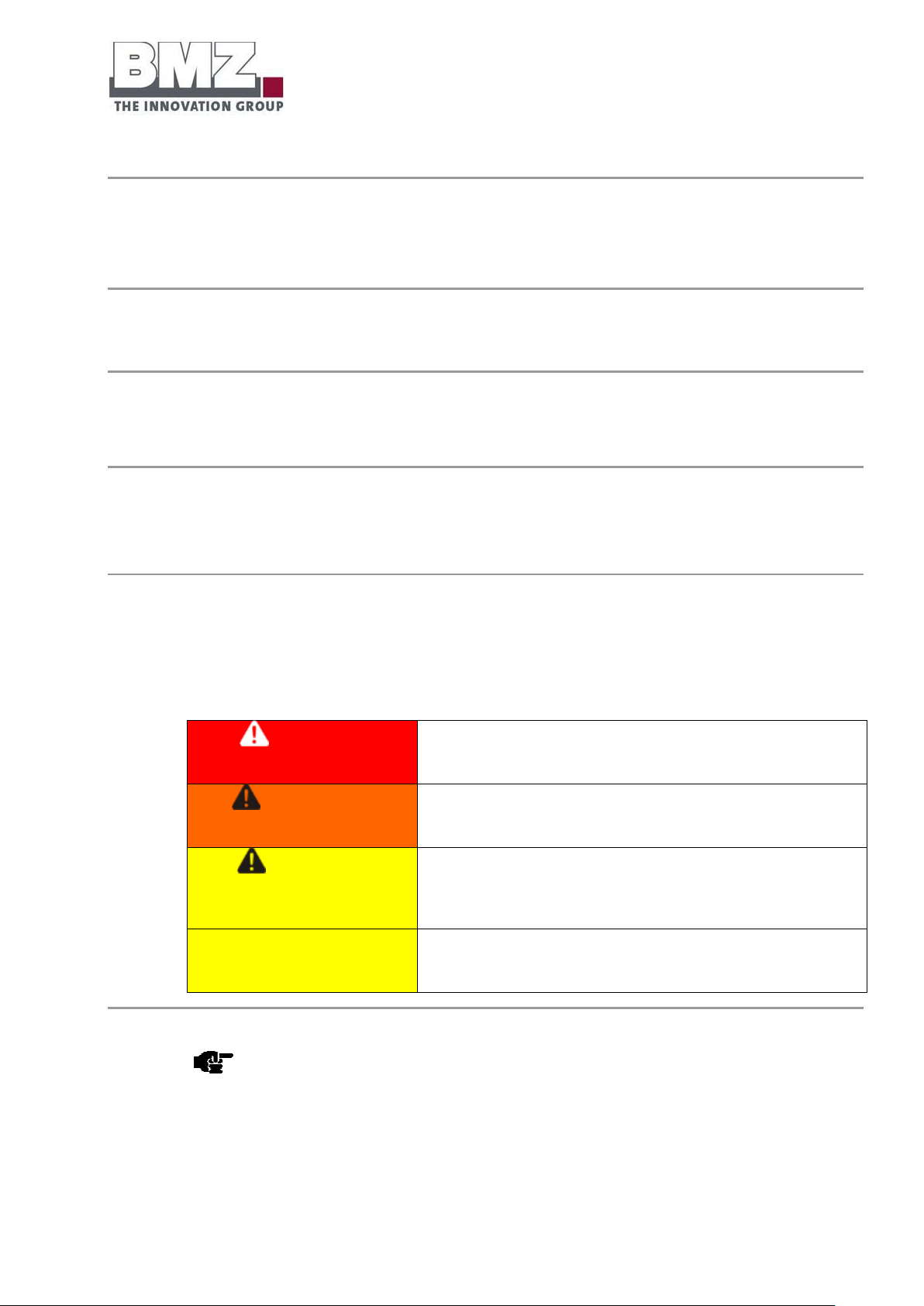
“DANGER” warns against hazardous situations. Prevent
these hazardous situations. Otherwise, they will lead to
deaths or serious injuries.
WARNING
“Warning” warns against hazardous situations. Prevent
these hazardous situations. Otherwise, they may lead to
deaths or serious injuries.
CAUTION
“CAUTION”, in combination with the warning icon, warns
against hazardous situations. Prevent these hazardous
situations. Otherwise, they may lead to insignificant or
minor injuries.
ATTENTION
“ATTENTION” indicates a possible hazardous situation.
Avoid these situations. Otherwise, they may damage the
machine.
1.1 Classification of warnings and intended use
Safety instructions
This section described warnings in this operating manual and the intended use of the machine.
1.1.1 Warnings in the operating manual
Warnings
Warnings serve as instructions and precautionary measures that must be followed and taken to avoid a
hazardous situation.
Classification of warnings
Warnings can be classified depending on the magnitude of a hazardous situation. The classification is based
on a probability assumption for an exposure to a hazardous situation and what could happen in such a case.
This manual differentiates between four warnings:
Note
This icon draws your attention to important, useful and helpful information.
Page 15
Safety
Version 1.0
Page 15 of 113
DANGER
Possible risk to life due to unintended usage
This battery system is exclusively intended for the aforementioned
purpose.
Any other use or a modification of the battery system without a written
consent of the manufacturer is considered to be unintended.
The manufacturer will not assume liability for any resultant damage. The
operating company shall bear full responsibility for any risk.
The battery system may be put into operation only if it is ensured that all
safety devices have been installed and functioning properly.
Never install or operate a potentially or obviously defective battery
storage.
Prevent these hazardous situations. Otherwise, they will lead to
deaths or serious injuries.
1.1.2 Intended use
Intended use of the battery system
The BMZ ESS 7.0 system must be exclusively used to store the current generated by the photovoltaic
systems.
Foreseeable misuse
Any other use is considered to be unintended. BMZ GmbH shall not be responsible for damage resulted
from this.
The BMZ ESS 7.0 system is primarily not approved for the following usages:
For a mobile use (e.g. on ships, in aeroplanes or in all types of land vehicles)
For operation in outdoor areas
For use in medical devices
For use as a UPS system
Intended usage also implies compliance with the usage and operating instructions specified by the
manufacturer as well as maintenance and servicing conditions.
Page 16

Safety
Version 1.0
Page 16 of 113
1.2 Safety instructions to be followed
WARNING
Possible risk due to inadequately qualified persons
Only a qualified electrician may carry out installation, servicing and
maintenance activities.
Prevent these hazardous situations. Otherwise, they may lead to
deaths or serious injuries.
Safety instructions
Follow the safety instructions in this section to ensure the safety of persons and the system.
1.2.1 General safety instructions
Target group
These general safety instructions are intended for all operators and operating companies of the battery
system.
Each person, who is entrusted with the installation, commissioning, operation, cleaning, maintenance and
repair activities, must have read and understood this operating manual, especially the Safety section.
Laws and regulations
Follow the instructions (regulations) of the relevant authorities as well as safety and operating instructions.
Spare parts
Only use original spare parts in case of repairs or when replacing the parts.
Using other parts that do not comply with our specifications may pose risks to persons and
the system.
BMZ GmbH shall not be liable for personal injuries and/or material damage resulting from
changes in the system.
Operator
Only a qualified electrician may operate/maintain the battery storage system.
Page 17

Safety
Version 1.0
Page 17 of 113
Suitable clothing (PPE)
Observe the following instructions regarding suitable clothing.
Always wear protective shoes. Class S3
Always wear ESD protective clothing.
Wear suitable protective gloves.
Wear suitable protective goggles.
Do not carry electrically conductive objects (jewellery, rings, watches, chains)
Condition of the battery storage system
Keep the battery storage system clean and in an excellent condition. Operate the battery system only if it is
in a flawless condition.
Other safety instructions
Follow the detailed safety instructions in Operation, Maintenance & Dismantling and Disposal sections.
Page 18
Safety
Version 1.0
Page 18 of 113
1.2.2 Safety instruction when working with the tool
WARNING
A forgotten tool poses the risk of injuries.
Do not keep any tools or metal parts on or in the battery.
If a tool is not removed before commissioning, it may cause a short-circuit
and injure persons or damage the system.
Only use the completely insulated tool.
Before commissioning/re-commissioning the battery system, ensure
that there are no tools in the battery system.
Prevent these hazardous situations. Otherwise, they may lead to
deaths or serious injuries.
Target group
These safety instructions are intended for all persons who are entrusted with the transport and installation
of the battery storage system.
Adhere to the operating manual
Always follow the instructions in the operating manual.
Working with the tool
Adhere to the following warning when using the tool:
Page 19

Safety
Version 1.0
Page 19 of 113
1.2.3 Safety instructions for transport and installation
DANGER
Risk of life due to live components
There is a risk of life in case of a contact with live components.
Only trained experts may work on the machine.
When working on the current circuit or on the battery, always
switch off the main switch first. Secure it with a padlock.
When working on the current circuit or on the battery, always
open the safety disconnection elements first. Secure the battery in
which the disconnection elements are spatially separated and kept.
Follow the 5 safety rules of battery technology.
Never install or operate a potentially or obviously defective battery
storage.
Prevent these hazardous situations. Otherwise, they will lead to
deaths or serious injuries.
Target group
These safety instructions are intended for all persons who are entrusted with the transport and installation
of the battery storage system.
Adhere to the operating manual
Always follow the instructions in the operating manual.
Adhere to the installation manual
Always follow the instructions in the installation manual.
Page 20
Safety
Version 1.0
Page 20 of 113
Safety instructions for transport and installation, continued
WARNING
Risk due to the loss of static stability
There is a risk of injuries due to the weight of the system.
The system may tilt or fall in case of improper transport.
Only use the transport aids that are suitable for the weight.
Ensure the correct weight distribution of the system when
transporting.
The transport aids must provide a braking effect in case of a steep
transport route.
Prevent these hazardous situations. Otherwise, they may lead to
deaths or serious injuries.
WARNING
Risk of injuries due to improper operation
Only trained experts may work on the system.
In case of maintenance and repair activities, the danger area is
extended by 1 m around the system. Pay attention to the swivel
range of the opening flap.
The operating company must ensure that the access to the danger
area is prevented during the movement sequences.
Prevent these hazardous situations. Otherwise, they may lead to
deaths or serious injuries.
Page 21
Safety
Version 1.0
Page 21 of 113
1.2.4 Safety instructions for operation
DANGER
Risk of life due to live components
When working on the electrical device, you may come in direct contact
with parts carrying electric potential. Such a direct contact causes an
electric shock.
Follow the 5 safety rules of battery technology.
Furthermore, only experts may maintain, modify or dismantle the
battery storage system.
Never install or operate a potentially or obviously defective battery
storage.
Prevent these hazardous situations. Otherwise, they will lead to
deaths or serious injuries.
DANGER
Danger due to erupting fire (electric hazard)
Fire may erupt during operation due to sparks or heated surfaces.
Follow the corresponding safety regulations (5 safety rules).
Furthermore, only experts may maintain, modify or dismantle
the battery storage system.
Never install or operate a potentially or obviously defective
battery storage.
Target group
These safety instructions are intended for all persons who are authorised to operate the battery storage
system.
Adhere to the operating manual
Always follow the instructions in this operating manual when operating the battery storage system.
Safety instructions for operation
Only use original parts of the manufacturer or the components approved by the manufacturer for the
energy storage unit.
Page 22
Safety
Version 1.0
Page 22 of 113
Prevent these hazardous situations. Otherwise, they will lead to
deaths or serious injuries.
Safety instructions for operation, continued
WARNING
Health hazards due to negligent use of personal protective
equipment
Working without personal protective equipment may cause serious
injuries.
Wear personal protective equipment (PPE).
Prevent these hazardous situations. Otherwise, they may lead to
deaths or serious injuries.
WARNING
Danger due to burns (electric hazard)
When working on the electrical device, you may come in direct
contact with defective and/or overloaded parts and get burns.
Follow the 5 safety rules of battery technology.
Furthermore, only experts may maintain, modify or dismantle the
battery storage system.
Prevent these hazardous situations. Otherwise, they may lead to
deaths or serious injuries.
Page 23
Safety
Version 1.0
Page 23 of 113
1.2.5 Safety instructions for cleaning
ATTENTION
Risk of damaged machine
Never clean the system or system parts using a vapour jet or spray
water.
Dirt and water may enter the system and cause major damage.
Use only a moist and clean cotton cloth for cleaning.
Avoid these situations. Otherwise, they may damage the machine.
Target group
These safety instructions are intended for all persons who are authorised to clean the battery storage
system.
Adhere to the operating manual
Always follow the instructions in the operating manual when cleaning the battery storage system.
Safety instructions for cleaning
Page 24

Safety
Version 1.0
Page 24 of 113
1.2.6 Safety instructions for maintenance and dismantling
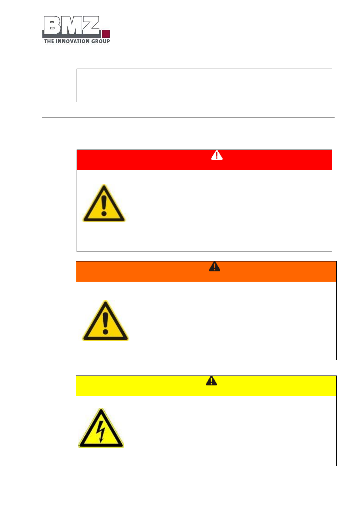
DANGER
Risk of life due to live components
There is a risk of life in case of a contact with live components.
Only trained experts may work on the system.
When working on the current circuit or on the battery, always switch
off the main switch first. Secure it with a padlock.
When working on the current circuit or on the battery, always open
the safety disconnection elements first. Secure the battery in which
the disconnection elements are spatially separated and kept.
Pay attention to the risk of electric arcs when pulling the NH1
isolator under the full load of the battery
Follow the 5 safety rules of battery technology.
Prevent these hazardous situations. Otherwise, they will lead to deaths
or serious injuries.
DANGER
Risk due to falling and being slung away
When working on the electrical device, a person may fall or slung
away due to a contact with parts carrying electric potential or parts with
electrostatic charges.
Follow the corresponding safety regulations
Furthermore, only experts may maintain, modify or dismantle the
Target group
These safety instructions are intended for all persons who are authorised to maintain/dismantle the battery
storage system.
Adhere to the operating manual
Always follow the instructions in this operating manual when maintaining/dismantling the battery storage
system.
Safety instructions for maintenance/dismantling
Observe the following warning when working on the electrical device:
Page 25
Safety
Version 1.0
Page 25 of 113
switch cabinet.
Prevent these hazardous situations. Otherwise, they will lead to
deaths or serious injuries.
DANGER
Danger due to erupting fire (electric hazard)
Fire may erupt during operation due to sparks or heated surfaces.
Follow the corresponding safety regulations (5 safety rules).
Furthermore, only experts may maintain, modify or dismantle the
switch cabinet.
Prevent these hazardous situations. Otherwise, they will lead to
deaths or serious injuries.
WARNING
Health hazards due to negligent use of personal protective
equipment
Working without personal protective equipment may cause serious
injuries.
Wear personal protective equipment (PPE).
Prevent these hazardous situations. Otherwise, they may lead to
deaths or serious injuries.
CAUTION
Danger due to burns (electric hazard)
When working on the electrical device, you may come in direct contact with
defective and/or overloaded parts and get burns.
Follow the corresponding safety regulations
Furthermore, only experts may maintain, modify or dismantle the
switch cabinet.
Safety instructions for maintenance/dismantling, continued
Page 26
Safety
Version 1.0
Page 26 of 113
Pay attention to the risk of electric arcs when pulling the NH1 isolator
under the full load of the battery
Prevent these hazardous situations. Otherwise, they may lead to
insignificant or minor injuries.
1.2.7 Safety instructions for battery interiors
DANGER
Danger due to leaking electrolyte
Only the trained experts and persons qualified and approved by BMZ
GmbH may work on the battery. Modifications or manipulations in the
battery may lead to considerable safety risks and are therefore
prohibited.
Do not solder cables to the battery.
Do not short circuit the battery.
Never open, dismantle, drill and crush the battery.
Never allow the battery to fall.
Do not expose batteries to rain or dip them in liquids.
Do not touch damaged batteries with bare hands. Lithium can
cause severe skin burns. Handle damaged batteries with suitable
safety equipment and tools.
Do not use defective, damaged or leaked batteries.
Do not use batteries that show discolouration, deformations,
unusual noises or severe heat.
Prevent these hazardous situations. Otherwise, they will lead to
deaths or serious injuries.
Target group
These safety instructions are intended for all persons who are authorised to work on battery modules of the
battery storage system.
Adhere to the operating manual
Always follow the instructions in the operating manual and in the specifications when working on these
modules.
Safety instructions for battery module
Page 27

Safety
Version 1.0
Page 27 of 113
Safety instructions for battery module, continued
DANGER
Danger due to leaking electrolyte
The materials / mediums to be used for intended operation of the battery
storage system are procured and used by the manufacturer of the system.
The manufacturer is thus solely responsible for the proper handling of
these materials / mediums and the associated hazards.
Hazard and disposal instructions must be provided by the manufacturer.
Follow the safety data sheets of material and medium manufacturers.
Prevent these hazardous situations. Otherwise, they will lead to
deaths or serious injuries.
Page 28
Safety
Version 1.0
Page 28 of 113
1.2.8 Safety instructions for fire prevention
WARNING
Possible risk of life due to electric shock when quenching fire or due
to flooding.
If you do not observe the following behavioural instructions, they may
cause material damage and personal injuries; BMZ GmbH shall not bear
any liability in such a case.
Switch off the battery storage system if it is possible without any
risk.
Notify the fire brigade immediately.
Help others and yourself to get out of the danger area
immediately.
Inform the fire brigade about the presence of Lithium-ion
batteries.
Prevent these hazardous situations. Otherwise, they may lead to
deaths or serious injuries.
Fire protection
Take essential precautions to respond efficiently in case of a fire.
Instructions for fire prevention
Pay attention to the following points:
Keep the fire extinguisher(s) in the immediate vicinity of the system. (Fire extinguisher
of fire class D)
Also keep in mind that poisonous vapours may be developed due to burning batteries
and may hamper and damage the function of respiratory tracts.
Hazard due to fire
The battery storage system does not pose a fire hazard. In case of a fire in the system, avoid its spreading to
other objects.
The battery storage system is de-energised at the time of delivery. Internal connection poles are always live.
Therefore, ensure that a tool or a metallic object is not kept in the battery system. This could lead to a
short-circuit and severe heat formation, which in turn could cause an explosion.
Actions to be taken in case of a damage
Page 29

Safety
Version 1.0
Page 29 of 113
Damaged cells and battery
Contact the manufacturer.
Never operate a potentially or obviously defective battery storage.
1.2.9 Explosion protection
General information
The battery storage system is de-energised at the time of delivery. Internal connection poles are always live.
Therefore, ensure that a tool or a metallic object is not kept in the battery storage system. This could lead to
a short-circuit and severe heat formation, which in turn could cause an explosion.
Explosive atmospheres
The battery storage system is not suitable for use in explosive atmospheres.
Ensure that there are no ignition sources in the within a radius of 3 m around the system.
1.2.10 Residual risks
General information
The battery storage system was designed such that no persons are exposed to avoidable hazards. Special
danger areas are secured using special safety devices.
Despite this, some danger areas still remain. When working on the battery storage system, you must be
aware of these danger areas, the actions to be taken to keep the risk of injuries and material damage
minimal.
This operating manual contains safety instructions to indicate these danger areas and essential actions to
minimise the risks resulting from such danger areas.
Page 30
Safety
Version 1.0
Page 30 of 113
1.3 Data and safety devices of the battery storage system
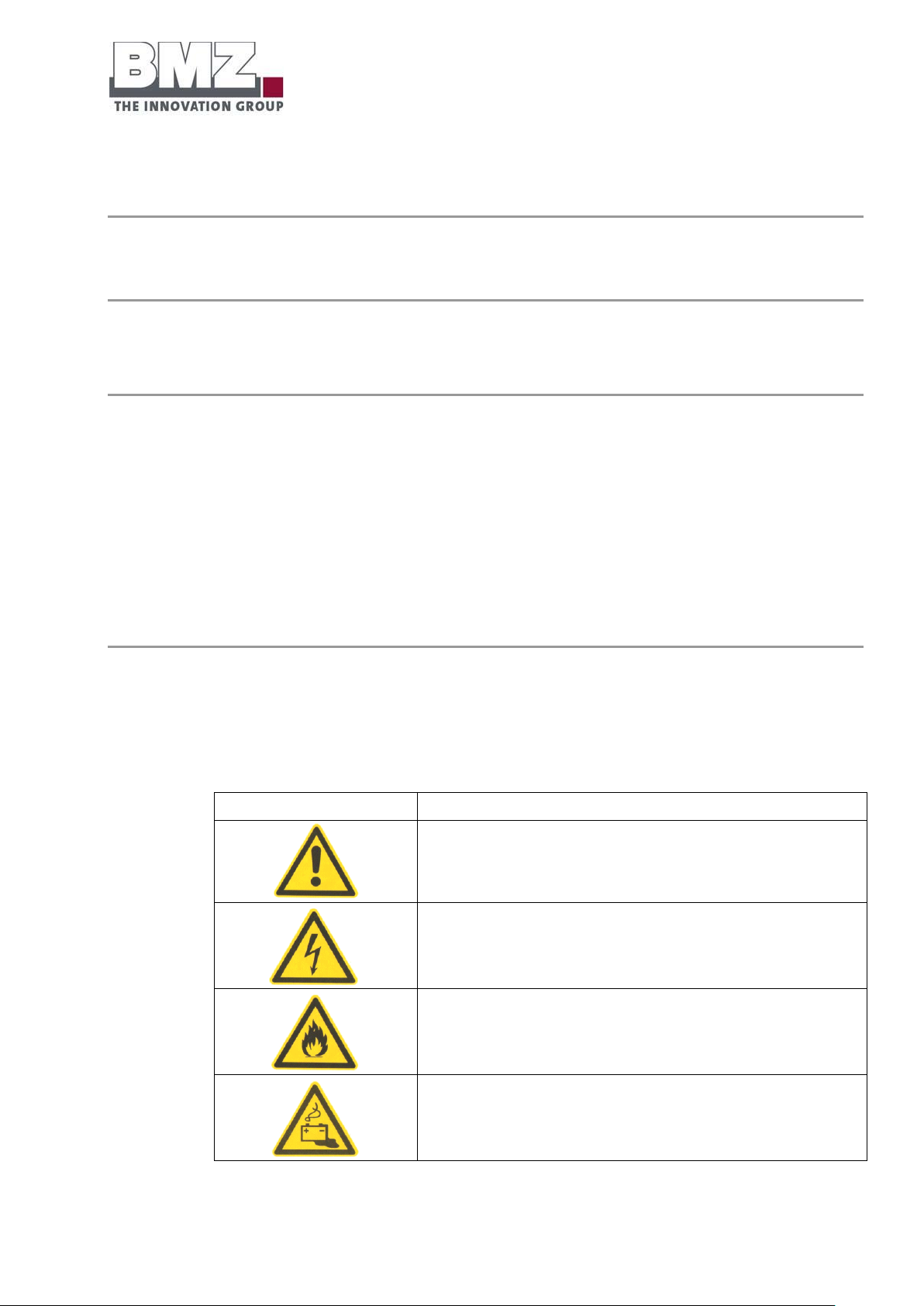
Symbol
Explanation
Warning against general hazard sources.
Warning against electric potential.
Warning against combustible materials.
Warning against risks posed by batteries.
Safety instructions
The data and devices for the safety of the battery storage system are specified in this section.
1.3.1 General hazard instructions and pictograms
Overview
Adhere to the safety systems and safety instructions described in this operating manual.
Keep the area around the battery storage system free from objects during operation to ensure that
unhindered access is always possible.
The NH isolator switches off all poles of the battery towards outside.
Pay attention to the risk of electric arcs when pulling the isolator under the full load of
the battery
Explanation of warning symbols and pictograms
The following warning symbols have been affixed on the battery storage system to be able to ensure the
safety of personnel and the battery storage system:
Page 31
Safety
Version 1.0
Page 31 of 113
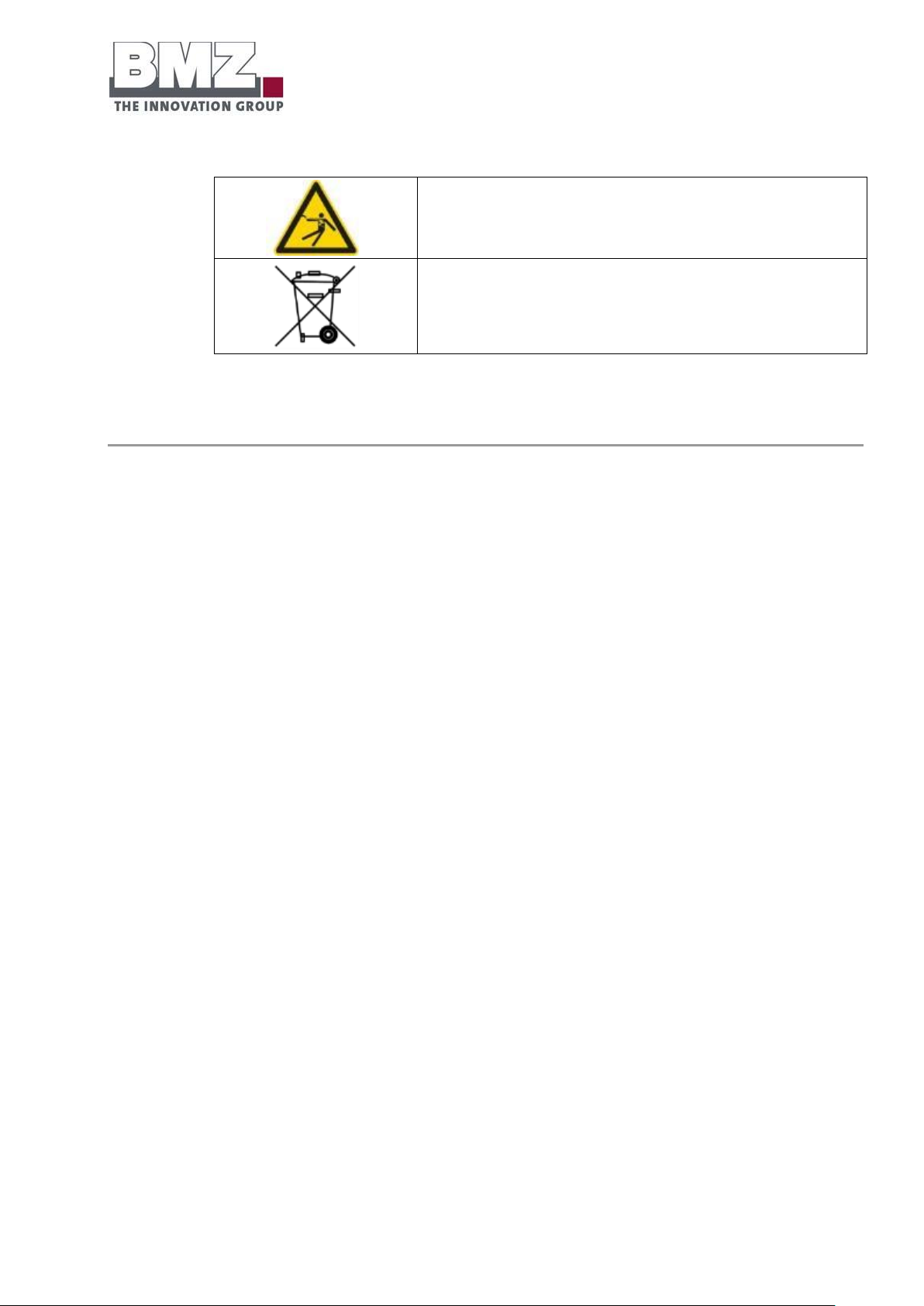
Warning against electric shock.
Do not dispose with household waste. Please return the battery
storage system to the manufacturer.
Table 1-1 Hazard instructions,
pictograms
Page 32
Safety
Version 1.0
Page 32 of 113
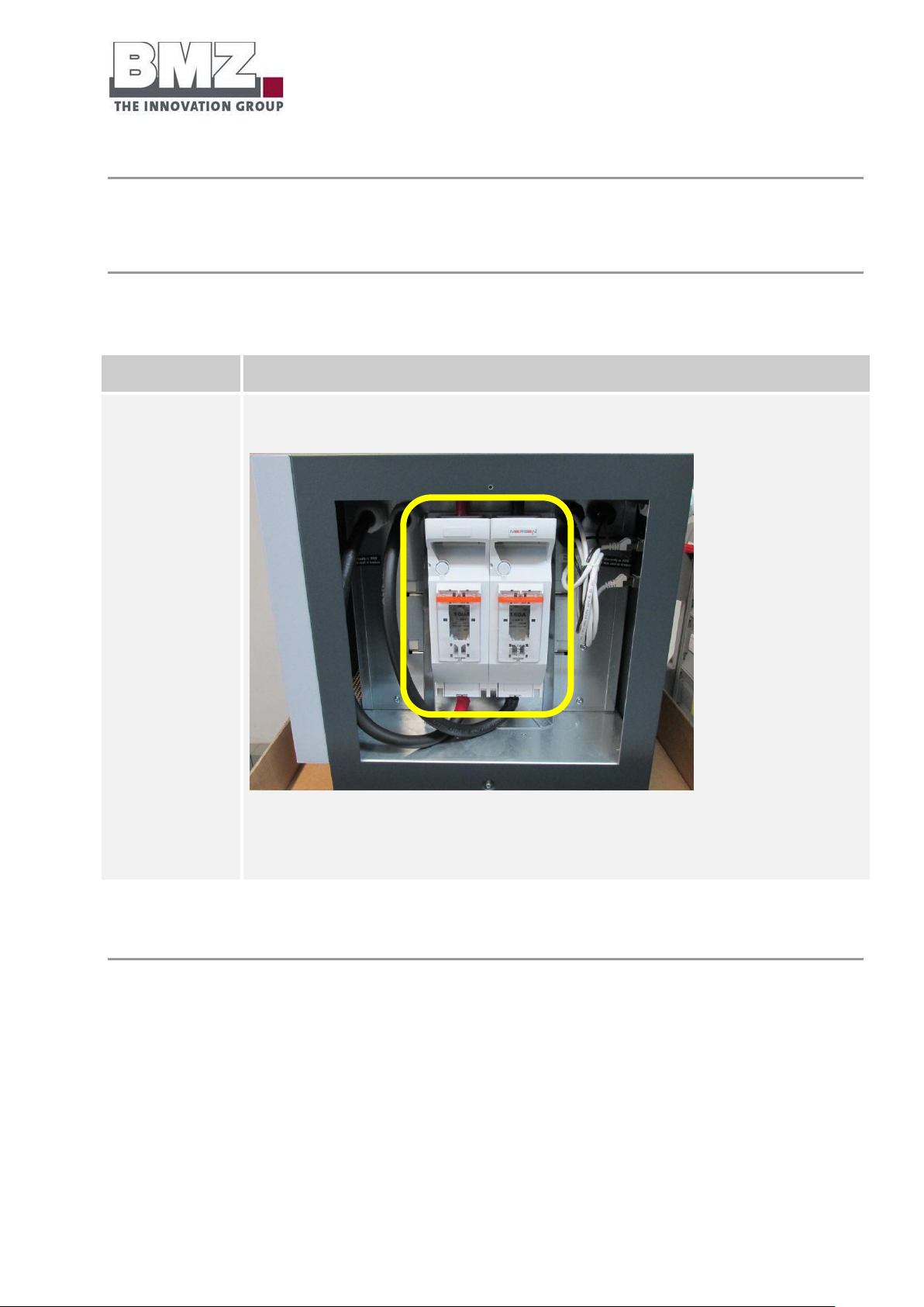
Description
Position
NH isolator switch
Connection area: outer housing
Figure 1-2: battery storage system, side view of NH1 isolator
1.3.2 Installed safety systems
Overview of safety systems of the battery storage system
The externally accessible fuse elements (NH1) ensure the line protection and short-circuit protection.
Page 33

Safety
Version 1.0
Page 33 of 113
1.3.3 Safety checks
Description
Position
Test scope
Technical test of the battery management system for flawless scope of functions
o Check whether communication between the battery and the inverter functions.
o Cell voltage test
o Temperature sensor test
Functional test of the battery at the inverter
Visual inspection of the finished product (outer housing)
Check the complete delivery scope.
General information
The following safety checks were conducted by the manufacturer in the factory.
Page 34

Function, delivery scope and technical key
variables
Version 1.0
Page 34 of 113
2 Function, delivery scope and technical key variables
Description
Quantity
BMZ ESS 7.0
1
CAN terminal resistance (integrated in the battery)
1
Operating manual
1
Installation check list (integrated in the operating manual; see section 10.3)
1
Warranty card (integrated in the operating manual; see section 10.2)
1
Test certificate
1
2.1 Function
Overview
The BMZ ESS 7.0 energy storage system stores electric energy in its electro-chemical intermediate storage.
This energy can then be retrieved later to compensate the daytime-dependent difference between the
power generation and power consumption.
In combination with a suitable inverter, the BMZ ESS 7.0 system also offers an option of standby power
function in case of a mains failure.
Thanks to the modular system, the required storage capacity can be flexibly arranged on the basis of the
BMZ ESS 7.0 system.
2.2 Delivery scope
Overview of standard delivery scope
The BMZ ESS 7.0 battery storage system is delivered with the following components:
Table 2-1: delivery scope
Page 35
Function, delivery scope and technical key
variables
Version 1.0
Page 35 of 113
2.3 System overview
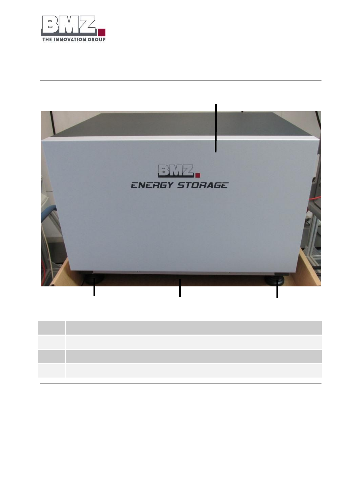
Position
Description
1
Battery housing
2
Supporting feet (adjustable height)
3
Air suction
1 3 2
2
Battery storage system:
Front view
Figure 2-2: battery storage system, front view
Page 36
Function, delivery scope and technical key
variables
Version 1.0
Page 36 of 113
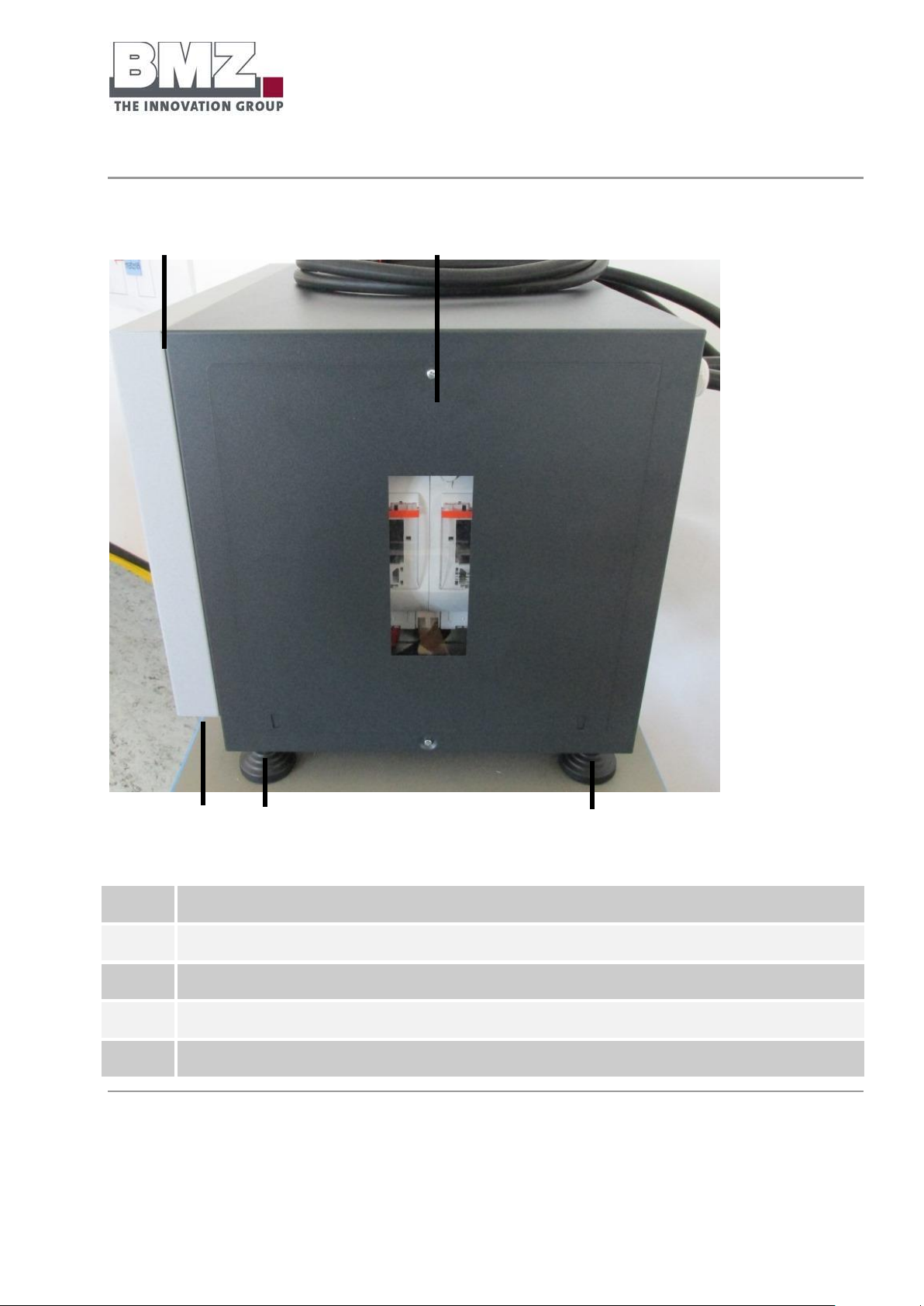
Battery storage system, side view
Position
Description
1
Battery housing
2
Removable side wall with an inspection window and NH1 fuses
3
Supporting feet (adjustable height)
4
Air suction
1 2 4 3 3
Figure 2-3: battery storage system, side view
Page 37
Function, delivery scope and technical key
variables
Version 1.0
Page 37 of 113
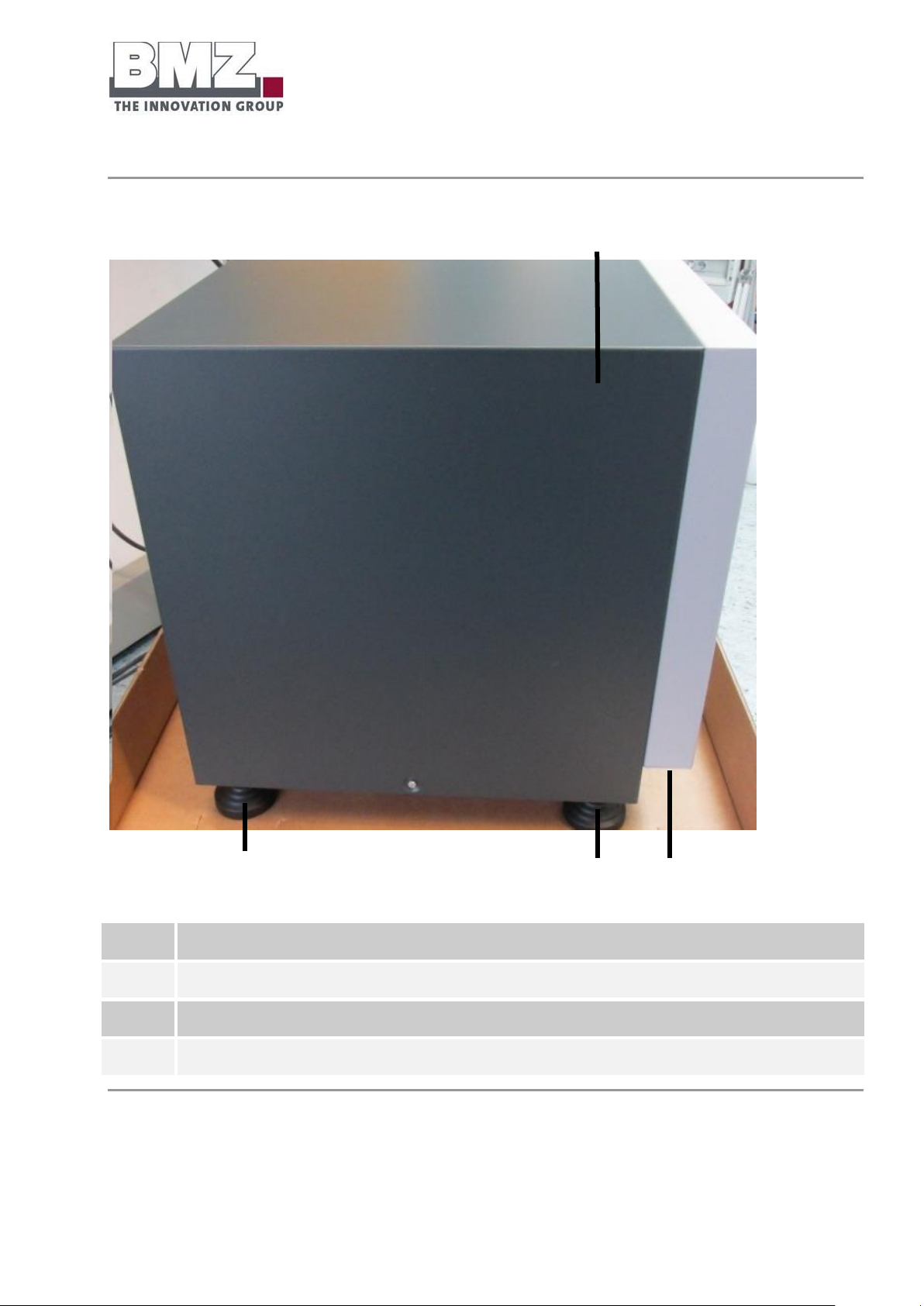
Battery storage system, side view
Position
Description
1
Battery housing
2
Air suction
3
Supporting feet (adjustable height)
2 3 3
1
Figure 2-4: battery storage system, side view
Page 38
Function, delivery scope and technical key
variables
Version 1.0
Page 38 of 113
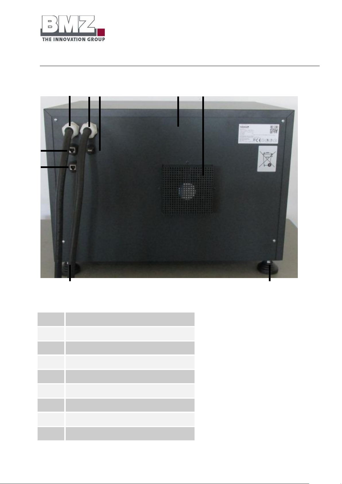
Battery storage system, rear view
Position
Description
1
Battery housing
2
Air outlet with fan
3
Supporting feet (adjustable height)
4
RS485 bus for multi-parallel mode
5
USB port
6
PLUS line with 50 mm2
7
CAN bus for inverter
8
MINUS line with 50 mm2
1 6 2 3 3 7 4 8 5
Figure 2-5: battery storage system, rear view
Page 39
Function, delivery scope and technical key
variables
Version 1.0
Page 39 of 113
2.4 Rating plates and warning stickers
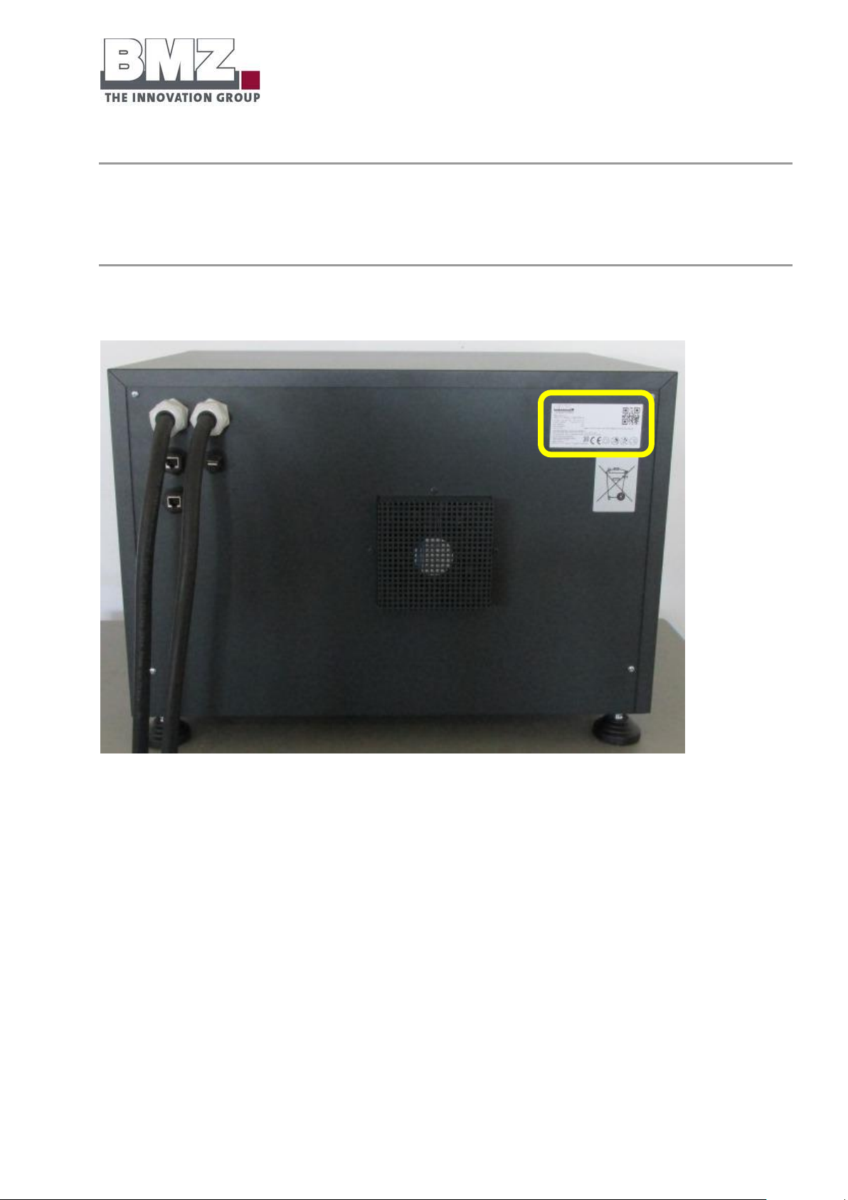
General information
The rating plate is provided on the rear side of the battery.
Figure 2-6: battery storage system, rear side
Page 40

Function, delivery scope and technical key
variables
Version 1.0
Page 40 of 113
Position
Description
1
Manufacturer / address
2
QR code (contents: www.bmz-gmbh.de)
3
Safety instruction: Read the operating manual without fail before installation or usage
4
Safety instruction: Do not operate a defective battery
5
Safety instruction: The battery must not become wet.
6
Recycling instruction symbol
7
CE mark
8
Serial number
9
Manufacturing year/month
10
Product name
11
QR code (contents: serial number)
12
Safety instruction: various safety instructions
1 2 3 6 5 4 7
8 9 10
11
12
Figure 2-7: rating plate
Table 2-8: rating plate
Page 41
Function, delivery scope and technical key
variables
Version 1.0
Page 41 of 113
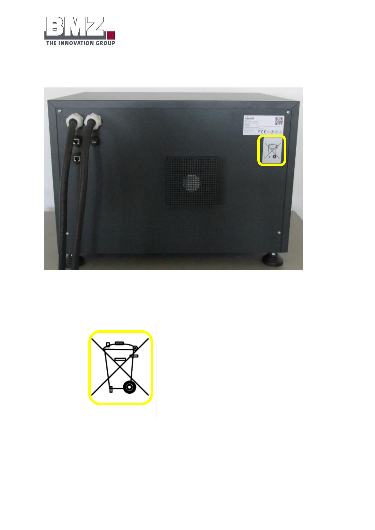
Recycling symbol
Figure 2-9: battery storage system, recycling symbol
Detailed view
Figure 2-10: recycling symbol
Page 42
Function, delivery scope and technical key
variables
Version 1.0
Page 42 of 113
2.5 Technical key variables
Battery storage
Unit
BMZ ESS 7.0
BMZ ESS 7.0 Premium
Energy content
kWh
6.743
6.743
Usable energy content
kWh
5.4
5.4
Nominal capacity C10
Ah
121.5
121.5
Nominal voltage
V
55.5
55.5
Expected calendar-based service
life
a
15
15
Expected cycle-based service life
5000
5000
Expected residual capacity at the
end of service life
%
70
70
Degree of efficiency at 25 °C
%
> 95
> 95
Cooling
active
active
Interfaces
CAN 2.0
CAN 2.0
Technology
Lithium Ion NMC
Lithium Ion NMC
Self discharge rate per month
%
1-3
1-3
Dimensions H/W/D
cm
Approximately 46 x 64 x 48
Approximately
57 x 68 x 48
Weight
kg
95
100
Certifications
UN 38.3; CE
UN 38.3; CE
Product data
The following table describes the variants of the BMZ ESS 7.0 system:
Table 2-11: overview of technical specifications
Page 43

Transport
Version 1.1
Page 43 of 113
3 Transport
3.1 Safety instructions for transport
Target group
Safety instructions intended for the installation personnel who transport, install and put the BMZ ESS 7.0
battery storage system in operation.
Safety instructions
For transporting the battery storage system and when working on electrical devices, please follow the safety
instructions from the Safety section, page 13.
3.2 Transporting the battery storage system
Delivery of the battery storage system
Delivery
The battery storage system is packed in a mechanically robust, three-walled corrugated
paper carton and delivered.
Incoming inspection
Check for the completeness using the delivery note.
Damage
Check the delivery for damage.
Visual inspection: e.g. damaged packing, scratches, dents, paint damage, missing
components)
In case of complaints:
Is the delivery damaged during transport:
Ask the forwarding agent to acknowledge obvious transport damage in writing
and on the site.
Contact the last forwarding agent immediately.
Store the packing (for a possible inspection by the forwarding agent or for
returning the product).
Page 44

Transport
Version 1.1
Page 44 of 113
Take photos for easier documentation.
Write a short fault report.
Never install or operate a potentially or obviously defective battery storage.
Check the goods at the time of acceptance
Before accepting the goods, check whether the shipment is complete and flawless. The operating manual
contains an exact list of all components.
Before accepting the goods, check whether the carton is broken, deformed or destroyed. In such case,
refuse the acceptance or accept only with conditions and a written confirmation of the forwarding agent.
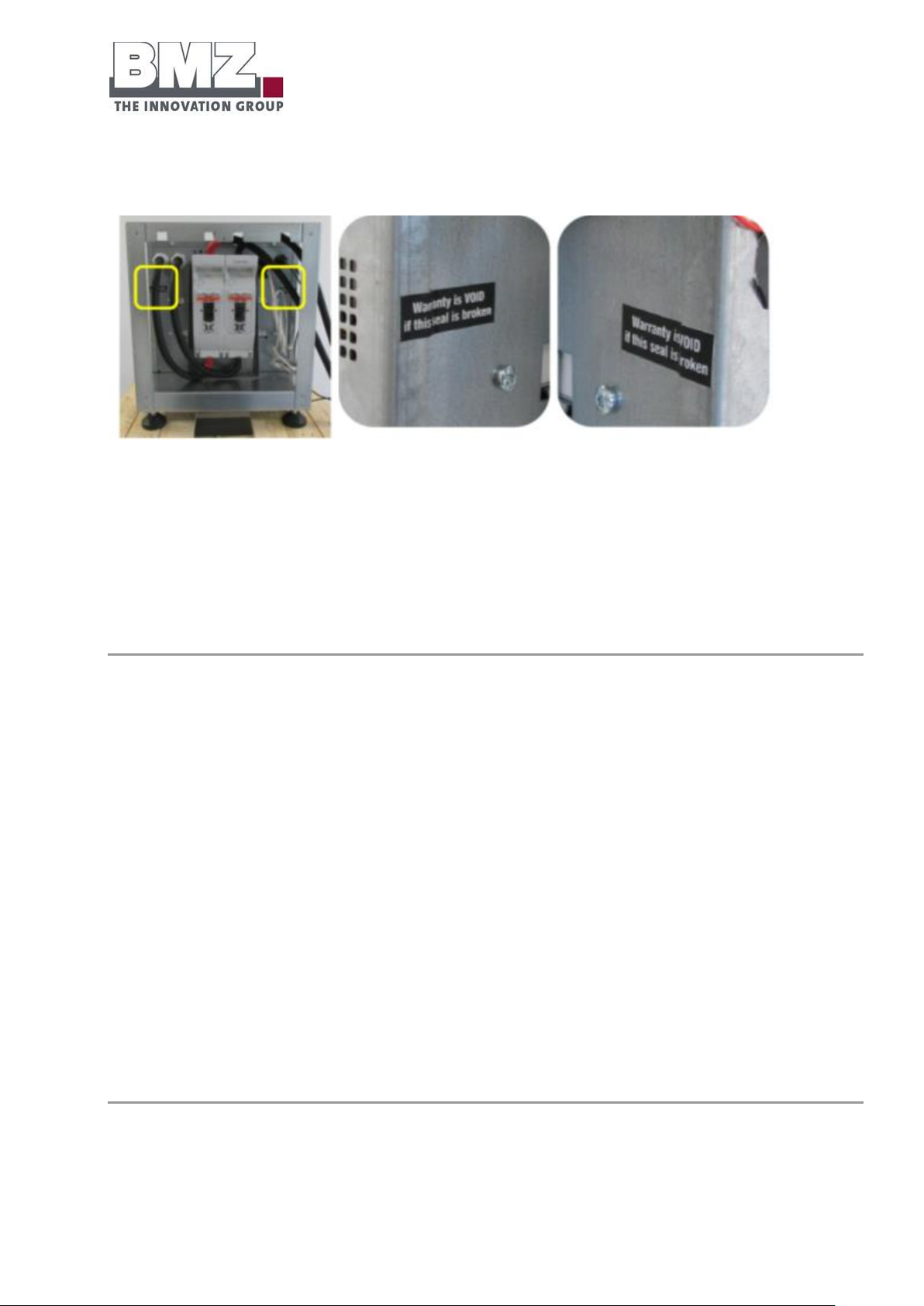
Immediately check whether the test seal in the battery is intact. The inner housing of the battery has 3 test
seals. If one test seal is destroyed, refuse to accept the goods.
If a test seal is destroyed, all guarantee and warranty claims for the product shall be void.
If the test seal is destroyed: Do not install or commission the energy storage system under any
circumstance.
Rear side of the battery inner housing
Figure 3-1: seal position
Page 45
Transport
Version 1.1
Page 45 of 113
Front side of the battery inner housing
Figure 3-2: seal position
Contents of the seal / translation of the seal:
English: Warranty is VOID if this seal is broken
German: Garantie / Gewährleistung ist ungültig, wenn dieses Siegel gebrochen ist
Packing for return shipment
If possible, use the original packing and the original packing material.
If both are no longer available, request a packing company with experts or contact the
manufacturer.
Place the transport units on a pallet (it must be designed depending on the weight).
Use the original packing material to protect the housing from scratches and transport
damage.
If you have queries regarding packing and transport safeguarding, please consult BMZ GmbH.
Contact
Telephone: 0049 (0)6188 99 56 9830
Email: [email protected]
Intermediate storage
The freight packing of the battery, spare parts and replacement parts are designed for a storage duration of
a maximum of 6 months from the delivery.
Page 46

Transport
Version 1.1
Page 46 of 113
Storage conditions:
Closed and dry room with a room temperature from +10 °C to +30 °C (temperatures
below and above this range shorten the service life)
Relative air humidity must be a maximum of 80% (non-condensing).
The spatial distance from walls or other objects must be at least 50 cm.
The battery storage system must be stored only in an upright position.
Never clean the battery storage system or its immediate vicinity using a vapour jet or spray water.
Dirt and water may enter the battery storage system and cause major damage.
Before storing the lithium ion battery, inform your insurer.
After a storage time of a maximum of 6 months, execute an equalisation charge process for the battery as
described in the operating manual of the battery inverter.
- If this is not done, batteries may get damaged.
- If this is not done, it will lead to consequential costs which will not be borne by BMZ.
The entire time of storage of batteries must be included in the usage duration.
Page 47
Transport
Version 1.1
Page 47 of 113
Transport to the installation site (of the customer)
WARNING
Risk of injuries due to improper transport.
Pay attention to the weight of the transport unit when transporting (see
technical specifications).
The transport unit may tilt during transport. Pay attention to the
centre of gravity.
If necessary, secure the transport unit using suitable lifting tackles
before transporting.
Prevent these hazardous situations. Otherwise, they may lead to
deaths or serious injuries.
Only the experts may carry out the transport in accordance with local conditions.
The commercial installer is authorised to transport an energy storage unit without the ADR note
for the transport of hazardous goods.
The free limit for such “transports of hazardous goods” is 333 kg or 999 points (net weight of
the hazardous product x 3 = points /ADR regulation). According to ADR, the identification of the
vehicle is essential from 1000 points onwards ad the driver must have an ADR note.
Every transport must be provided with an accompanying document (transport document as per
ADR hazardous goods UN3480) irrespective of the points.
The transport units are transported on pallets and exclusively in original packages up to the customer’s
installation site.
The product must be installed out of the reach of children and animals.
Page 48

Transport
Version 1.1
Page 48 of 113
Step
Description
1
Place the energy storage unit, with the contact with the rear wall, on the sack truck.
Figure 3-3: transporting with the sack truck
Use a soft protective cloth to protect the energy storage unit from scratches.
In case of steps, only use the specially designed step sack trucks.
2
Secure the energy storage unit with tightening straps on sack trucks.
Transport with a sack truck
The sack truck must be designed for the weight of transport units.
Page 49

Installation, assembly and commissioning
for the first time
Version 1.1
Page 49 of 113
4 Installation, assembly and commissioning for the first
time
General information
Only the experts trained by BMZ GmbH may carry out the installation, assembly and first commissioning
activities.
4.1 Installation site requirements
Installation site
The BMZ ESS 7.0 battery storage system is only intended for usage in buildings.
The battery housing has been designed for a stack of up to 3 battery storage systems.
Use the structural analysis of the building to check whether it is designed for the load of the system.
Each energy storage unit weighs approximately 95 kg. If three energy storage units are stacked on each
other, intermittent loads of a maximum of 285 kg act on the floor.
The installation site must fulfil the following requirements:
Levelled (e.g.: maximum setting range of adjusting feet)
Dry (maximum air humidity 80%)
Clean (well-swept, dust free)
Vibration-free (maximum shock 0.5 g)
No direct solar radiation
No naked flames or other ignition sources near the installation place (minimum
distance 3 m)
Adequate distance (at least 20 cm) between the battery storage system and walls
Adequate air circulation to dissipate the heat generated by the battery storage
system.
Installation site below 2000-metre altitude.
Page 50

Installation, assembly and commissioning
for the first time
Version 1.1
Page 50 of 113
Figure 4-1 : requirements for the installation site, distance of the ESS from walls, top view
Figure 4-2 : requirements for the installation site, distance of the ESS from walls, side view
The room air must not contain contaminations like suspended particles, metal dust or combustible gases.
Ensure that the air humidity does not exceed 80%.
Page 51

Installation, assembly and commissioning
for the first time
Version 1.1
Page 51 of 113
The room temperature should be in a range from 0 °C to 25 °C, wherein 15-20 °C are optimum for a long
service life.
Operate the battery storage system only in the upright position.
Ensure that the service flap at the side (NH1 fuses) is always freely accessible.
Install the battery inverter and the battery storage system near each other. Do not lay the connecting cable
between the battery and the inverter in windings. The maximum length of this cable is 2.3 m.
Only use the provided original cable.
Do not shorten the cable arbitrarily.
Do not extend the cable arbitrarily.
Do not lay the cable in loops.
Immediate surroundings of the battery storage system
The immediate surroundings of batteries must be clean and dry. Oil contaminations, dirt or water residues
must not be found outside the battery. If contaminations are found, remove them immediately. Additional
information regarding this is given in: VDE 0510 Part 2: 2001-12, EN 50272-2: 2001 “Safety requirements for
batteries and battery systems – part 2: stationary batteries”.
4.2 Filling the warranty card
The customer / installer must fill the warranty card carefully; it shall be valid only with a signature and the
company stamp. Send the duly filled warranty card to BMZ GmbH. The warranty card is given in the annexe
of this manual.
Guarantee and warranty claims against the manufacturer can be asserted only if the installed battery has
been registered with the manufacturer along with the filled warranty card.
4.3 Filling the installation check list
The installer must fill the installation check list carefully; it shall be valid only with a signature and the
company stamp. Send the duly filled installation check list to BMZ GmbH. The installation check list is given
in the annexe of this manual.
Guarantee and warranty claims against the manufacturer can be asserted only if the installed battery has
been registered with the manufacturer along with the filled installation check list.
Page 52
Installation, assembly and commissioning
for the first time
Version 1.1
Page 52 of 113
4.4 Installation of the battery storage system
Step
Description
1
Unpack the battery storage system carefully and check it for transport damage.
In case of transport damage, contact the forwarding agent or the manufacturer immediately.
Do not use a knife to open the packing.
Never install and operate a defective energy storage unit
2
Check whether all structural parts and accessories exist.
3
Check whether the battery storage system has been switched off.
Both LEDs must not light up.
Use a voltmeter to measure the DC voltage.
4
Bring the battery storage system on the pallet to the installation place using suitable transport aids.
5
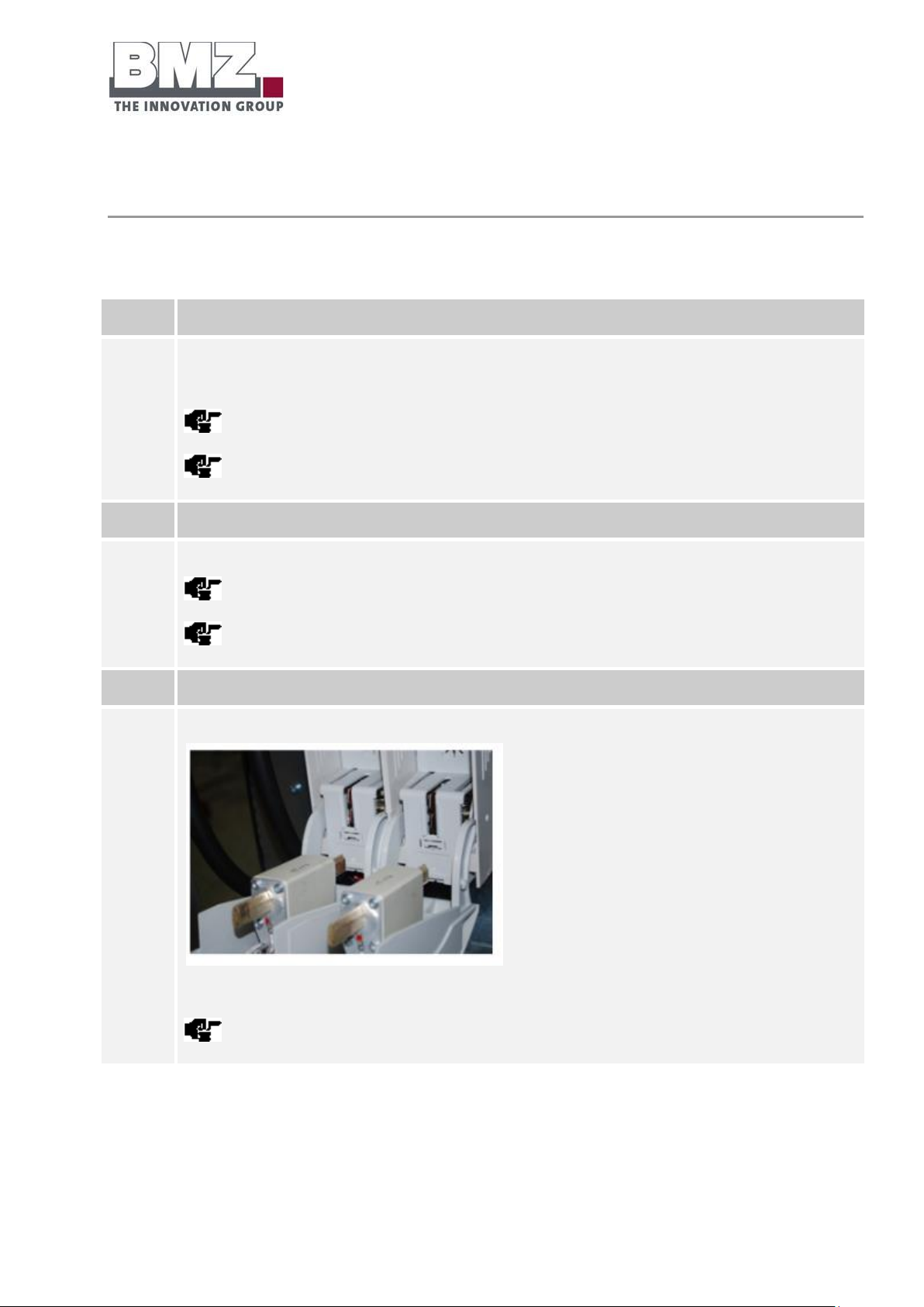
Check whether the current isolator (NH isolator) is pulled.
Figure 4-3: representation of the pulled current isolator
The current isolator must be pulled before installation.
Installation steps
Proceed as follows to install the battery storage system:
Page 53

Installation, assembly and commissioning
for the first time
Version 1.1
Page 53 of 113
6
Use a suitable lifting device to lift the battery storage system from the pallet (e.g. workshop crane).
7
Position the battery storage system on the installation site.
Adhere to the minimum distances from walls. (See section 4.1 Requirements for the installation site)
Page 54
Installation, assembly and commissioning
for the first time
Version 1.1
Page 54 of 113
4.5 Preparing the electrical connections for the single mode
Step
Description
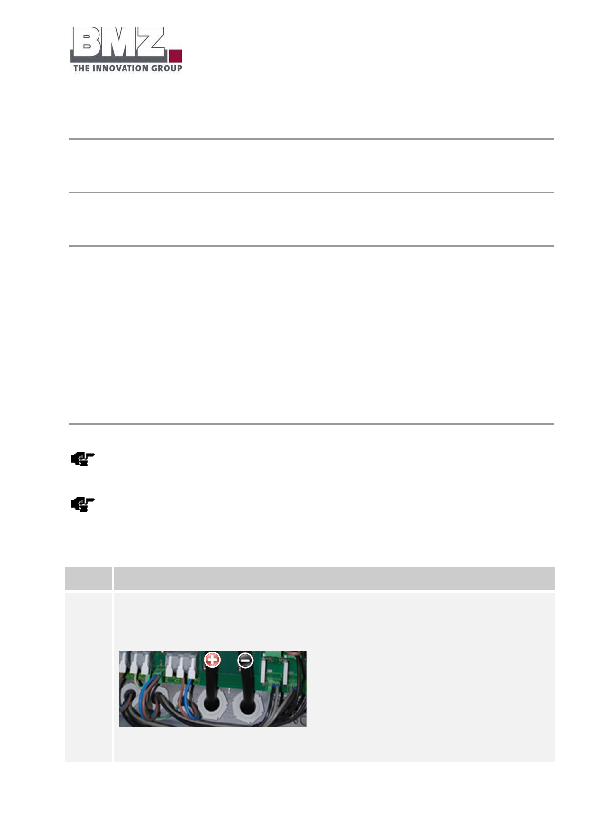
1
Push the 50 mm² lines through metric screw joints into the housing of the inverter.
Plus pole = RED
Minus pole = BLACK
Figure 4-4: inverter, connection area for battery lines
Definition of single mode:
Single mode means the operation of a BMZ ESS 7.0 energy storage system at an inverter.
Safety instructions
Please follow the safety instructions in the Safety section, page 13.
Establish the connections between the inverter and the battery
Pre-conditions:
The current isolator (NH isolator) must be pulled
The battery inverter must be switched off (“Off”)
Check for the correct polarity carefully before establishing connections. Connection lines are marked in
different colours:
Plus pole = RED
Minus pole = BLACK
The connection of a battery with an SMA Sunny Island inverter is described below as an example.
When using another inverter, please follow the specifications in the corresponding manufacturer’s
documentation.
Check whether the inverter used by you is approved for use with the BMZ ESS 7.0 battery storage
system.
Page 55

Installation, assembly and commissioning
for the first time
Version 1.1
Page 55 of 113
The 50 mm² connection lines must NOT be connected to incorrect poles.
Follow the installation manual of the inverter manufacturer.
2
Connect the power cable of the battery inverter to the poles of the NT isolator.
Use the 2 screws of the M8x20 size as well as washers and tension washers.
Figure 4-5: sample representation of the connection of plus and minus power cables with the SMA Sunny Island
inverter
Ensure that the contact surface of cable shoes rests completely.
Maximum tightening torque: 12 Nm. (Tolerance +/- 5 Nm)
3
Connect the CAN communication cable between the inverter and the battery storage system.
For this purpose, patch the patch cable (RJ45) from the CAN socket of the battery storage system to the CAN socket
of the inverter. (Marked in yellow)
Figure 4-6: representation of external connections of the battery system, CAN
4
Insert the NH fuses in the cover of the NH isolator.
Page 56
Installation, assembly and commissioning
for the first time
Version 1.1
Page 56 of 113
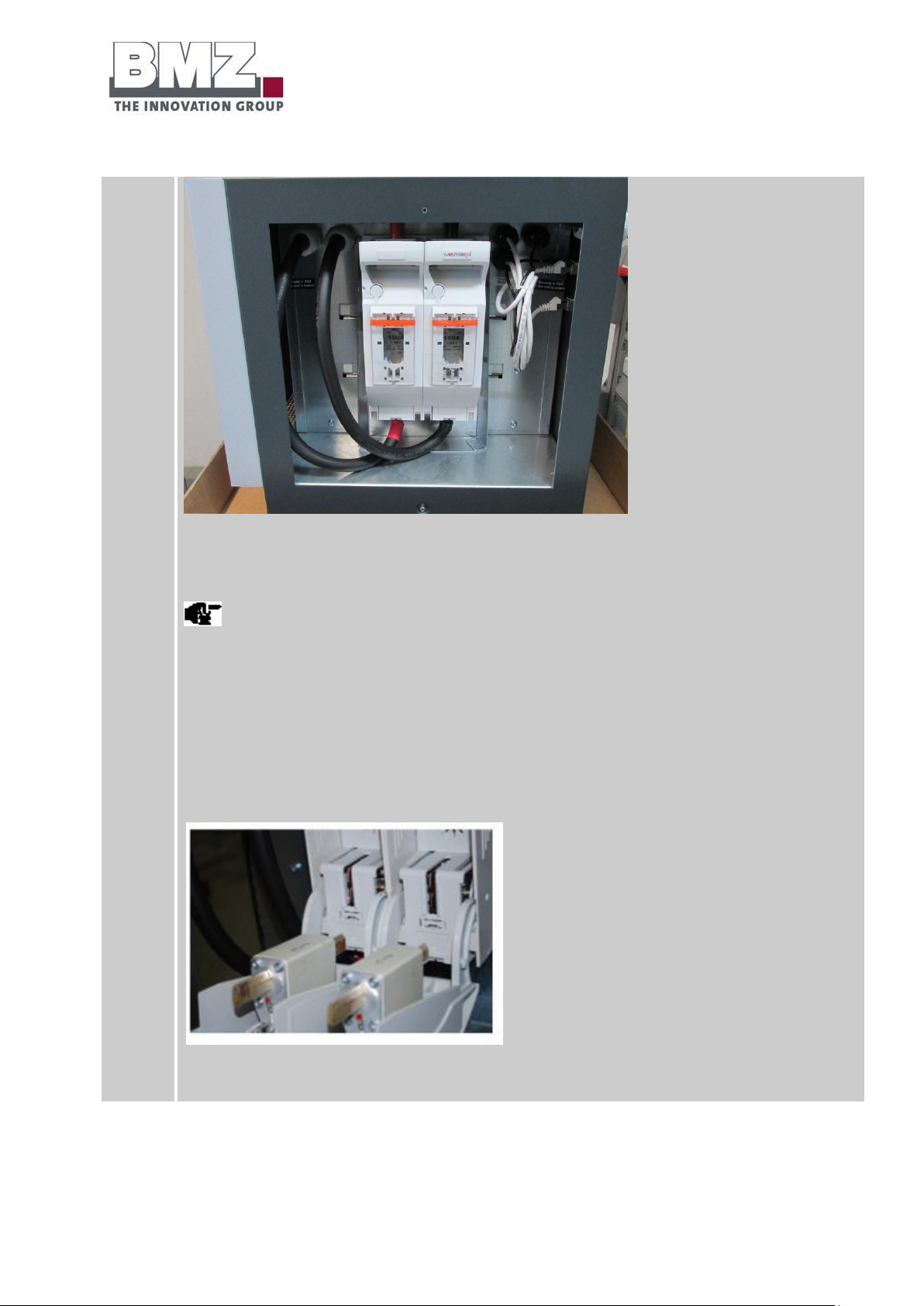
Figure 4-7: battery storage system, side view of the opened housing
Change the fuse inserts depending on the inverter to which the battery is connected.
Recommendation:
SI3.0M-11: 80 A
SI4.4M-11: 100 A
SI6.0H-11: 160 A
SI8.0H-11: 200 A
Figure 4-8: representation of the correctly inserted fuses
Page 57

Installation, assembly and commissioning
for the first time
Version 1.1
Page 57 of 113
5
Insert the housing cover in the housing and tighten the screws of the cover.
For this purpose, use 2 DIN 7985 M4x6 fillister-head screws. Fix these using a PH2 Phillips screwdriver and a
maximum tightening torque of 2.5 Nm (tolerance: +/-0.1 Nm).
Figure 4-9: battery storage system, side view
The cover may remain open during the first installation in order to switch on the battery. Close the cover after
switching on the battery
6
Execute the first commissioning process by following the specifications from the Operation section (page 94).
7
Configure the parameters of the inverter as mentioned in section 4.18 (Recommended parameters).
Detailed view:
Ensure that the batteries are not earthed by mistake. If they are earthed, disconnect the
corresponding connection.
Check all parts for firm fitting. Re-tighten all screws and terminals.
4.5.1 Checking the connections
Check the connections as per the exact specifications in the installation check list given in the annexe.
Page 58
Installation, assembly and commissioning
for the first time
Version 1.1
Page 58 of 113
Step
Description
1
Open the screws on the service flat using a PH2 screwdriver.
2
Check whether the NH isolator is equipped with correct (see section 4.5) NH fuses and put into operation
correctly.
3
Check the connections of the DC power cable (+, -) and the CAN communication cable of the battery inverter.
4
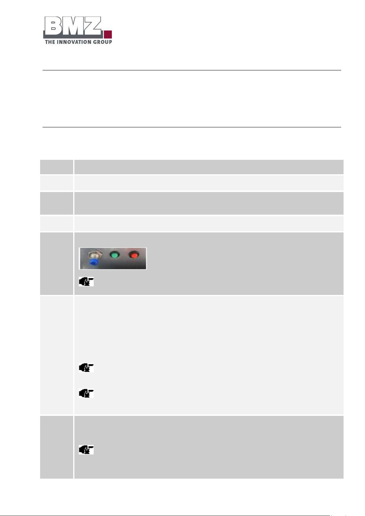
Actuate the push button through a short (longer than 1 second) push.
A clicking sound must be heard.
5
Check the LED status of the battery storage system.
The green LED flashes quickly (every 100 msec): The pre-charging path is activated and charges the
capacitors of the inverter. (The pre-charging time depends on the type and number of connected inverters.
The pre-charging time can take from 30 seconds to 2 minutes)
Both LEDs flashes slowly (every 1 second): The battery is active and waits for communication through the
inverter.
The battery switches off automatically after 20 minutes if there is no communication between the battery
and the inverter.
Additional information regarding the LED flashing patterns is given in the Pilot lamps section,
page 95.
6
Switch on the battery inverter.
The green LED lights up continuously
If there is no communication between the battery storage system and the inverter, the battery switches
off automatically after 20 minutes to avoid erroneous operating modes. Both LEDs flash in a one-second cycle
if there is no communication.
4.5.2 Switching the battery storage system on and off
The battery storage system and the inverter must be correctly installed before they can be put into
operation.
Switch on the battery storage system using a switch
Proceed as follows to start the battery storage system:
Page 59
Installation, assembly and commissioning
for the first time
Version 1.1
Page 59 of 113
Switch on the battery storage system using an external voltage source
Step
Description
1
The external voltage source can be used to switch on the system only if it was not switched off using the push
button (press the push button longer than 10 seconds at a stretch).
2
Connect an external voltage source greater than 36 VDC.
3
The battery detects the external voltage source automatically and switches the operating mode from inactive to
active.
4
If it is switched on in an unauthorised manner, the green LED flashes quickly (100 ms flash cycle)
You must now start the battery using a normal switch-on sequence (by pressing the push button longer than 1
second).
Step
Description
1
Open the screws on the service flat using a PH2 screwdriver.
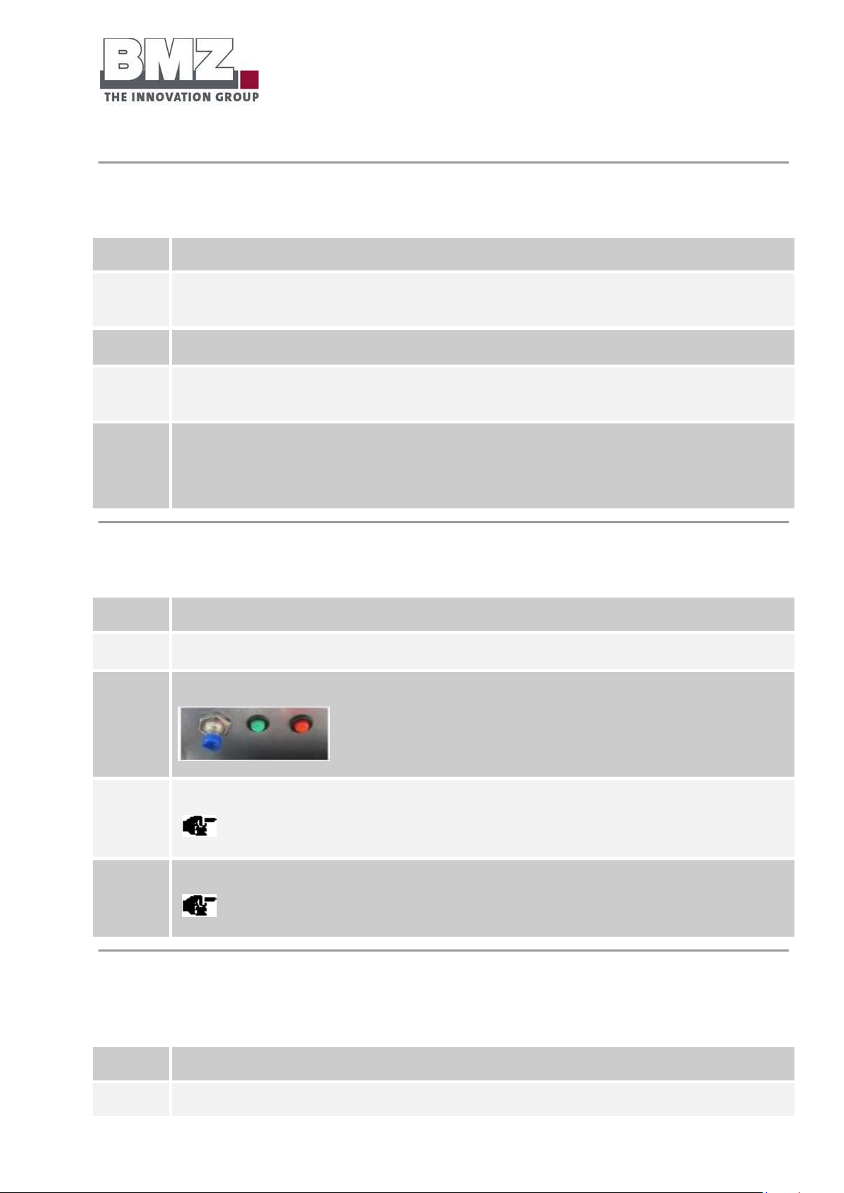
2
Keep the switch-on button pressed for at least 10 seconds.
3
After approximately 8 seconds, both LEDs start flashing quickly (100 ms flash cycle).
Keep the button pressed for 2 more seconds.
4
The LEDs switch off. The battery storage system is now switched off.
A clicking sound must be heard.
Step
Description
1
If an external source (e.g. the battery inverter) does not detect a CAN communication of the battery, the battery
Proceed as follows to start the battery storage system:
Switch off the battery storage system using a push button
Proceed as follows to switch off the battery storage system:
Switch off the battery storage system using time
The battery switches off automatically after a defined time of 20 minutes when the battery does not detect
any CAN communication externally.
Page 60

Installation, assembly and commissioning
for the first time
Version 1.1
Page 60 of 113
switches off automatically after 20 minutes.
4.5.3 Configuring the parameters of the inverter
The inverter parameters must be configured for the BMZ ESS 7.0 battery in order to operate it optimally in
combination with the inverter.
See section 4.18
Page 61

Installation, assembly and commissioning
for the first time
Version 1.1
Page 61 of 113
4.6 Preparing the electrical connections for the parallel mode
Definition of parallel mode:
Parallel mode means the operation of multiple BMZ ESS 7.0 energy storage systems at one or more
inverters.
Safety instructions
Please follow the safety instructions in the Safety section, page 13.
The following safety instructions are additionally applicable for the parallel operation:
If the battery is operated under full load, housing parts and lines may generate heat.
When wiring the batteries, ensure that a short-circuit is never formed between the plus and minus
poles of one or more batteries. There is a risk of life.
When laying the lines, do not extend them from the plus and minus poles.
When laying the lines (plus and minus poles), ensure that they are not rolled.
Establish the connections between the inverter and the battery
Pre-conditions:
The current isolator (NH isolator) of each battery must be pulled
The battery inverter must be switched off (“Off”)
Use a suitable switch cabinet to connect the batteries in the parallel circuit to the inverters.
BMZ recommends using a DC busbar with a suitable line fuse for each connected line.
BMZ recommends using products of SMA (Bat fuse) or Enwitec (BAT BREAKER BOX)
Check for the correct polarity carefully before establishing connections. Connection lines are marked in
different colours:
Plus pole = RED
Minus pole = BLACK
Page 62

Installation, assembly and commissioning
for the first time
Version 1.1
Page 62 of 113
Prerequisites for the battery firmware version
Batteries can be connected in parallel from firmware version V2.00 onwards.
The BMZ Service Tool in a specific version (at least Version 0.0.26) must be used to update the battery
to a new firmware version.
Requirements for the battery inverter
The parallel connection capability of BMZ ESS 7.0 batteries is approved only with the battery inverters
of SMA Sunny Island.
Check whether the inverter used by you is approved for use with the BMZ ESS 7.0 battery storage
system.
4.7 Connection concept of multiple BMZ ESS 7.0 batteries with one or more
battery inverters
4.7.1 Communication
Wiring of the communication line from the battery to the inverter
- Connect the CAN cable to the battery that has been configured as the master and connected with
the inverter.
Wiring of the communication line from between the batteries (internal communication
of battery)
- All batteries in the parallel circuit are connected with each other via the RS485 bus for internal
communication between them. The batteries are connected in a bus topology. For this purpose, Tconnectors (or even Y-adapters) are used at the RJ45 sockets (“INTERNAL” label) of batteries.
- One T-connector (or even a Y-adapter) is used for each battery.
Page 63
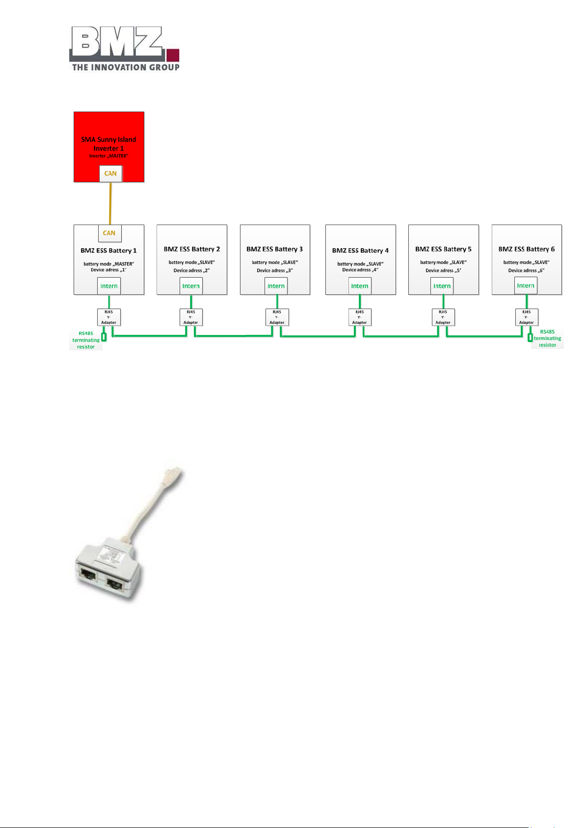
Installation, assembly and commissioning
for the first time
Version 1.1
Page 63 of 113
Figure 4-10: communication cabling, ESS parallel connection
- The RS485 bus must be closed with 120 Ohm at both ends
Example of a RJ45 T-connector (or even a Y-adapter) with corresponding pin assignment
Figure 4-11: RJ45 Y-adapter (even RJ45 T-connector)
Page 64
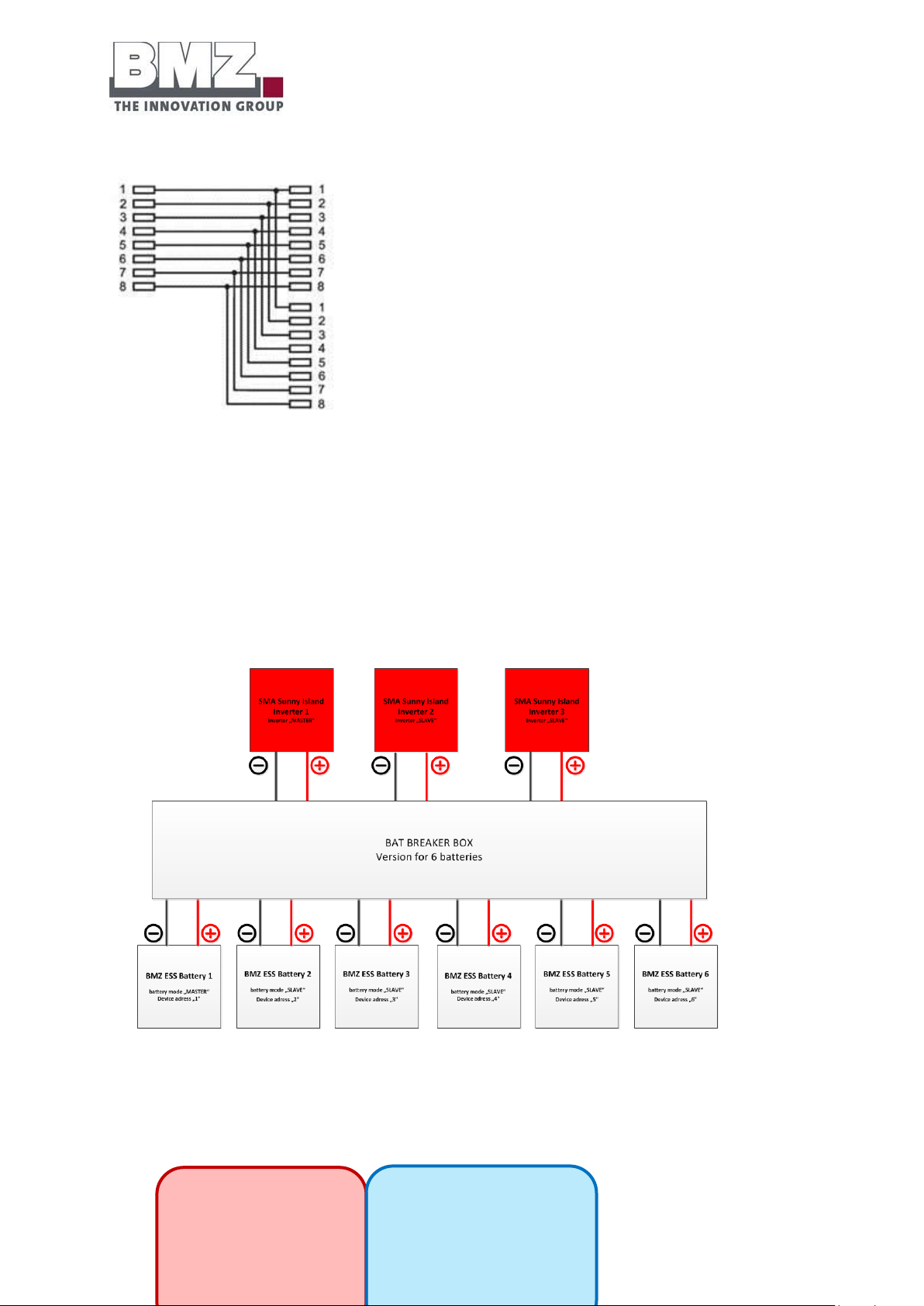
Installation, assembly and commissioning
for the first time
Version 1.1
Page 64 of 113
Connection of the
plus pole of
inverter
Connection of the
minus pole of
inverter
Figure 4-12: pin assignment of RJ45 Y-adapter (T-connector)
4.7.2 Output contact
- All plus poles of batteries must be laid on a copper rail using the Bat Breaker Box.
- All minus poles of batteries must be laid on a copper rail using the Bat Breaker Box.
Important: A short-circuit between the lines from the plus pole of the battery and the minus pole of the
battery must be prevented under any circumstance.
Figure 4-13: output cable of BAT Breaker Box
Page 65
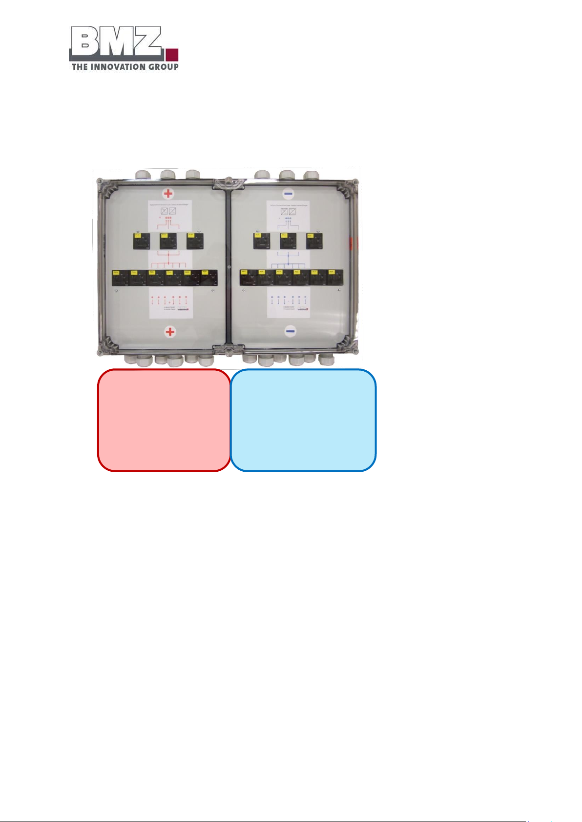
Installation, assembly and commissioning
for the first time
Version 1.1
Page 65 of 113
Connection of the
plus poles of
batteries (6 units)
Connection of the
minus poles of
batteries (6 units)
Figure 4-14: BAT BREAKER Box of Enwitec (example for 6 batteries and 3 inverters) with a closed housing
Page 66
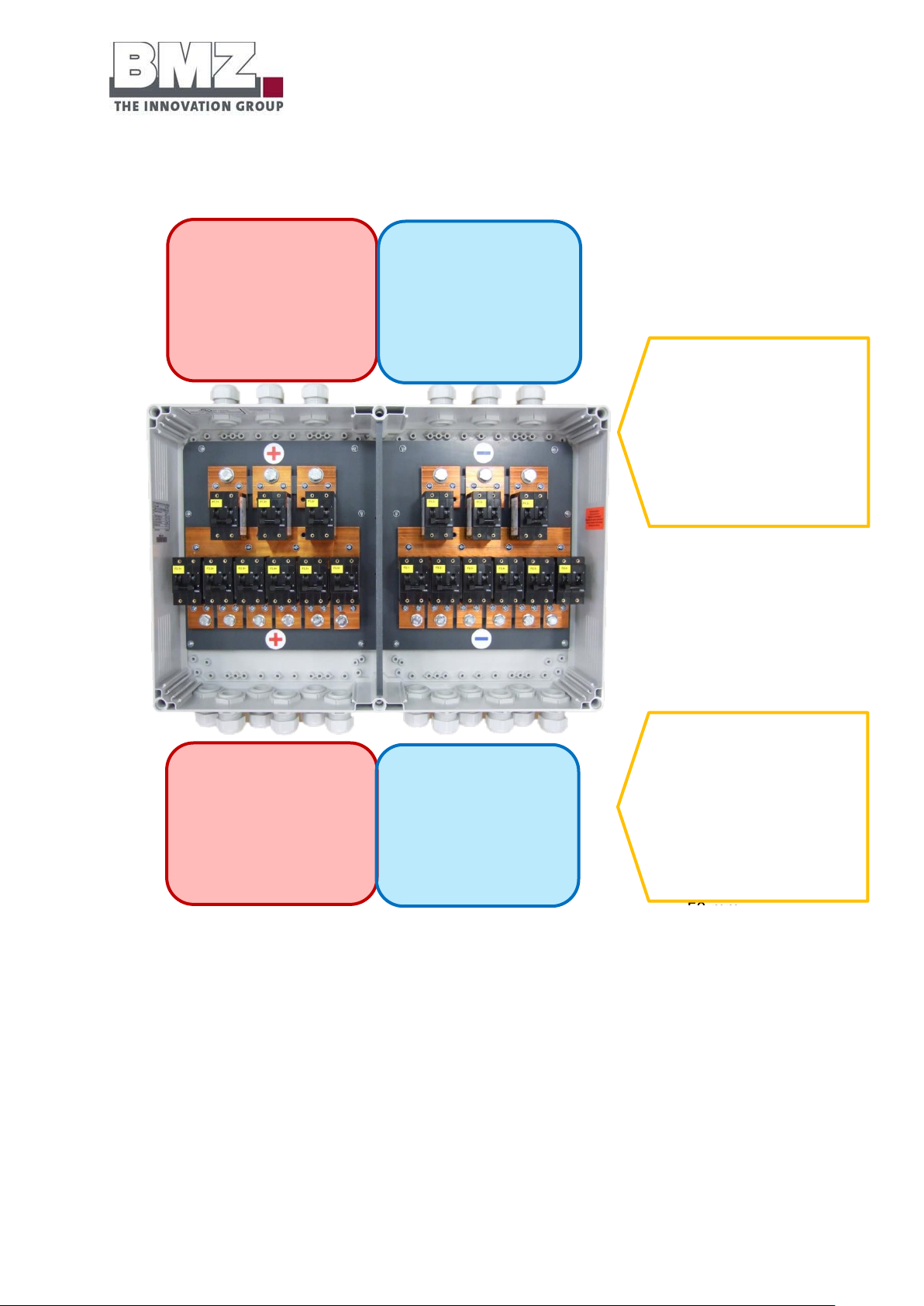
Installation, assembly and commissioning
for the first time
Version 1.1
Page 66 of 113
Connection of the
plus pole of
inverter
(3 units)
Connection of
the minus pole of
inverter
(3 units)
Connection of the
plus poles of
batteries (6 units)
Connection of
the minus poles
of batteries (6
units)
Connection side of
inverter
Cable shoe M10
Maximum Cu cross-
Connection side of
battery
Cable shoe M8
Maximum Cu cross-
section:
Figure 4-15: BAT BREAKER Box of Enwitec (example for 6 batteries and 3 inverters) with an open housing
Important:
Please refer to the installation manual of the manufacturer for additional instructions regarding installation
and operation.
Page 67
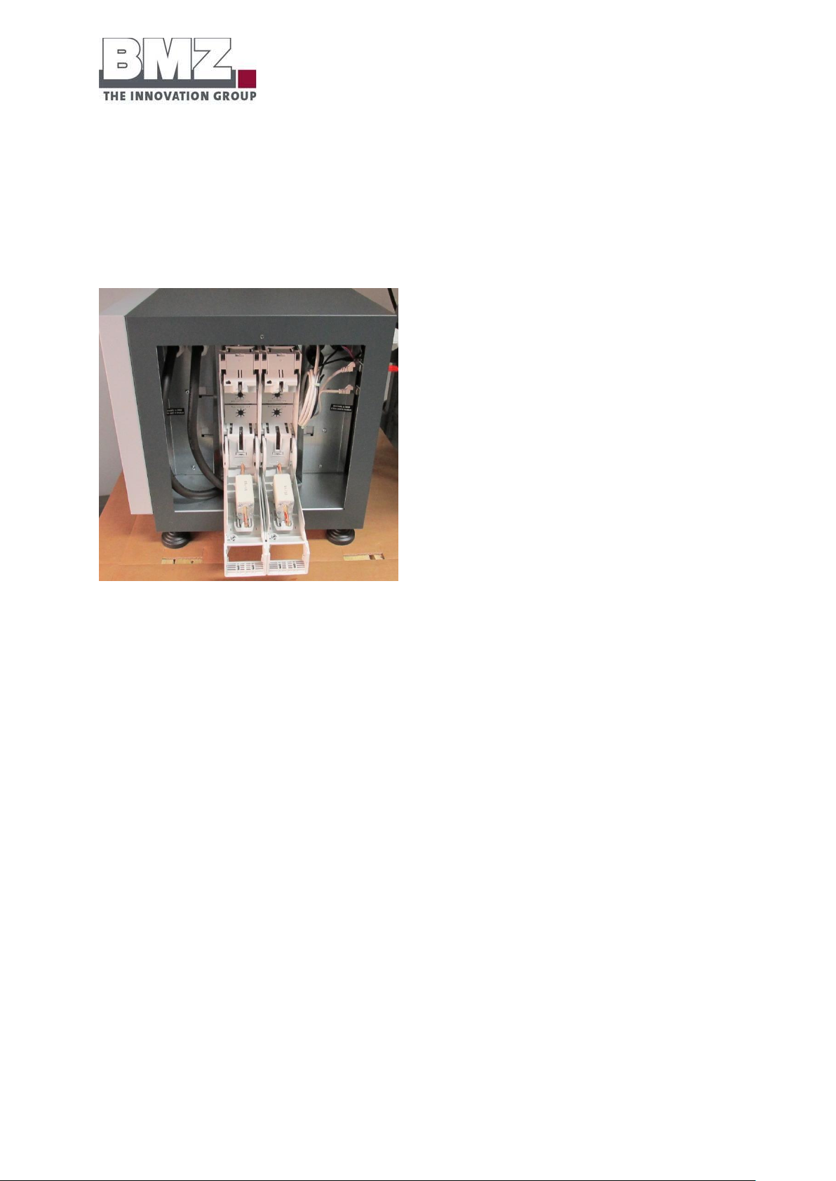
Installation, assembly and commissioning
for the first time
Version 1.1
Page 67 of 113
Important:
When interconnecting the output contacts, all fuses (NH1 isolators) of individual batteries and the
switch cabinet are removed, and the automats in the BAT BREAKER Box are set to OFF.
Figure 4-16: battery storage system, side view, power isolator pulled
Page 68
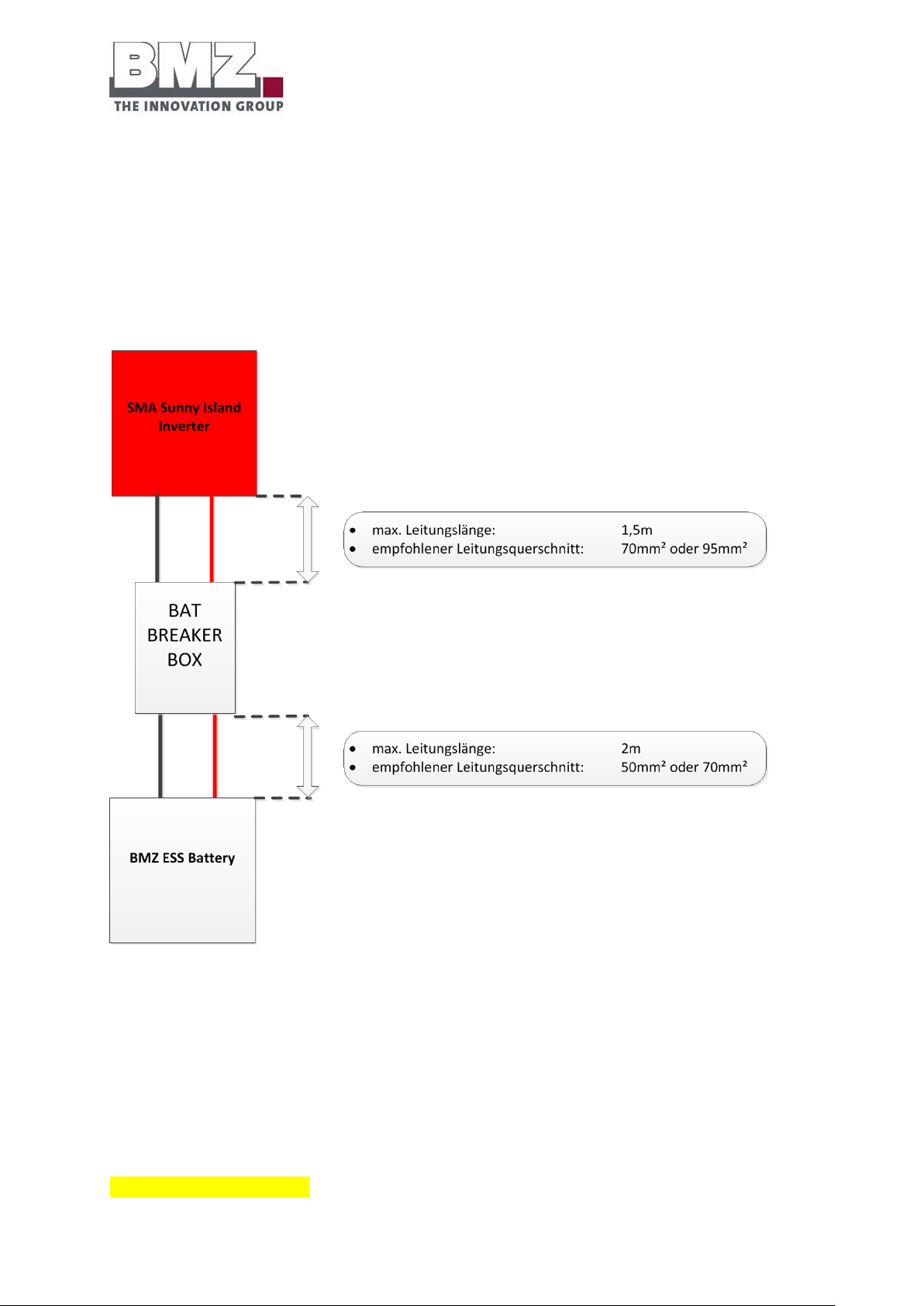
Installation, assembly and commissioning
for the first time
Version 1.1
Page 68 of 113
4.7.3 Laying the power cable
- The power cable should be as short as required.
- The length of the Pack+ and Pack- cables must not exceed the respective maximum lengths.
- Cables of each battery (plus and minus poles) must always have the equal length.
- Cables of a battery connected in a parallel circuit must have the equal length between the batteries.
Figure 4-17: cable lengths of the ESS system
Important: Connection of the power cable
When wiring the Bat Breaker Box (output rail), ensure that only Pack PLUS is connected to Pack PLUS
potentials.
When wiring the Bat Breaker Box (output rail), ensure that only Pack MINUS is connected to Pack MINUS
potentials.
RISK OF A SHORT-CIRCUIT!!!
Page 69
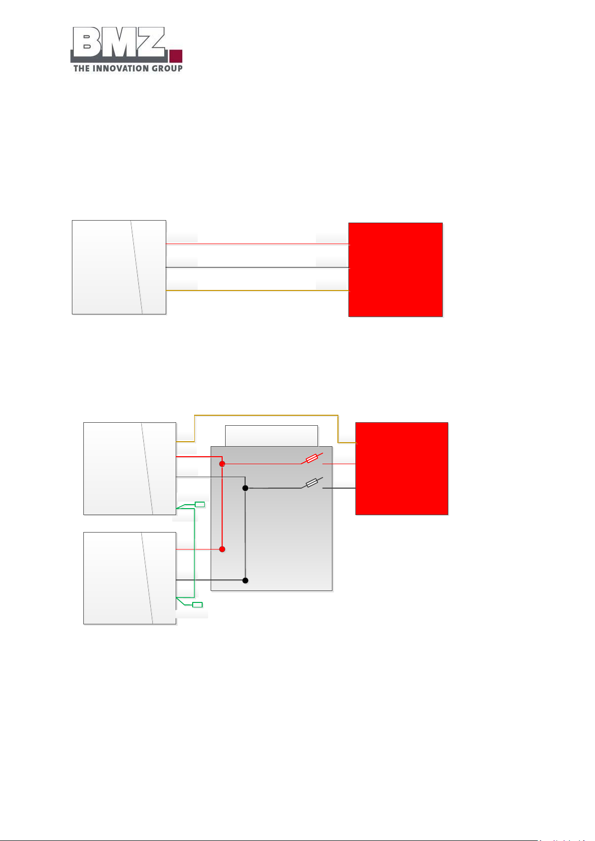
Installation, assembly and commissioning
for the first time
Version 1.1
Page 69 of 113
4.8 Configuration of the ESS parallel mode
BMZ ESS Battery 1
battery mode „SINGLE“
Device adress „1"
SMA Sunny Island
Inverter 1
PLUS
MINUS
CAN
PLUS
MINUS
CAN
CAN
Intern
CAN
MINUS
PLUS
MINUS
PLUS
Intern
PLUS
MINUS
BMZ ESS Battery 1
battery mode „MASTER“
Device adress „1"
SMA Sunny Island
Inverter 1
BMZ ESS Battery 2
battery mode „SLAVE“
Device adress „2"
BAT BREAKER 2er
RS485 terminating
resistor
RS485 terminating
resistor
Thanks to the modular concept of the BMZ ESS 7.0 system, different configurations of BMZ ESS 7.0 batteries
with SMA Sunny Island inverters are possible.
4.8.1 1-phase operation of a SMA Sunny Island inverter on 1 ESS battery
Figure 4-18 : 1-phase operation on 1 ESS battery
Figure 4-19: 1-phase operation on 2 ESS batteries
4.8.2 1-phase operation of a SMA Sunny Island inverter on 2 ESS batteries
Page 70
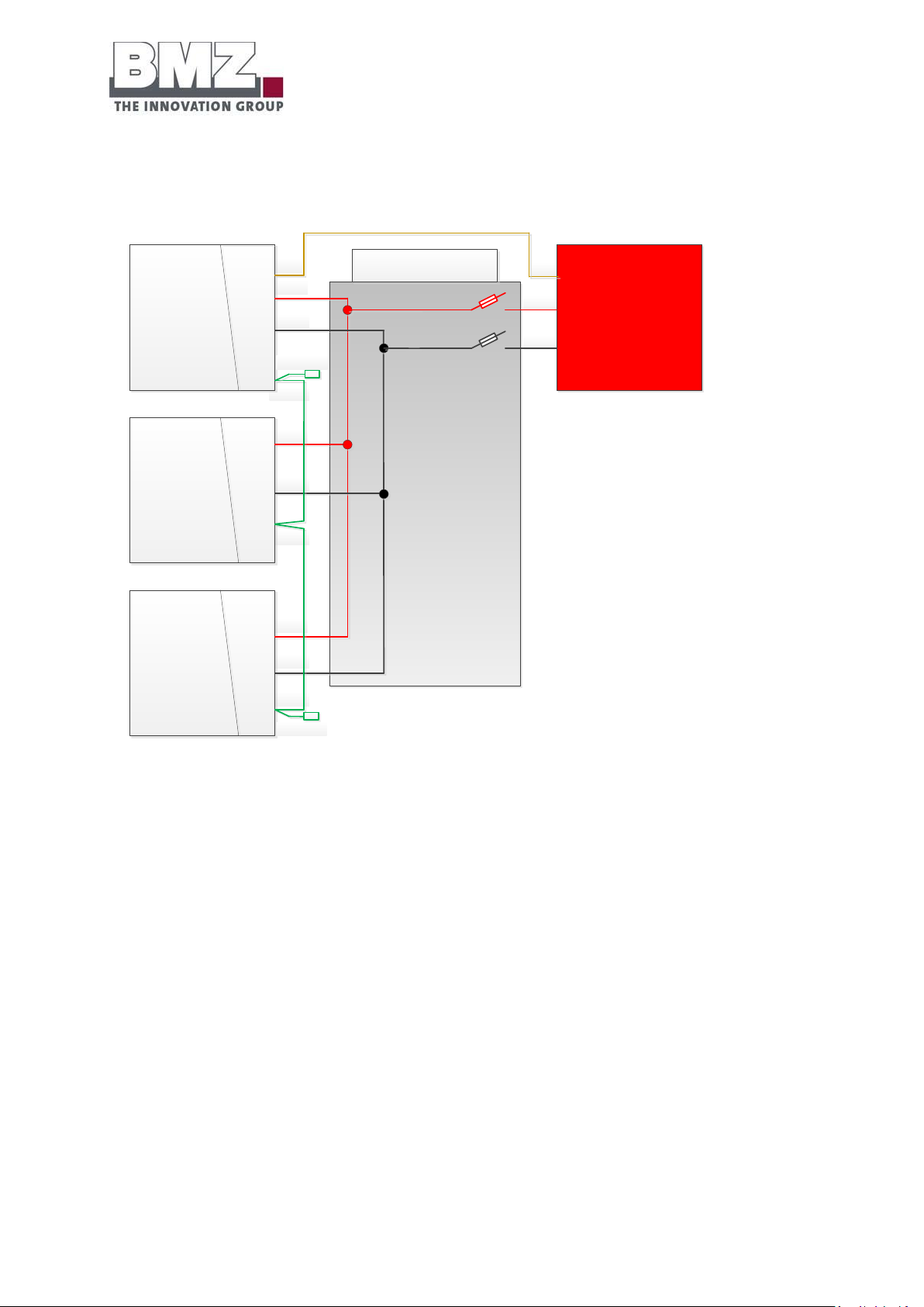
Installation, assembly and commissioning
for the first time
Version 1.1
Page 70 of 113
4.8.3 1-phase operation of a SMA Sunny Island inverter on 3 ESS batteries
CAN
Intern
CAN
MINUS
PLUS
Intern
MINUS
PLUS
MINUS
PLUS
Intern
PLUS
MINUS
BMZ ESS Battery 1
battery mode „MASTER“
Device adress „1"
SMA Sunny Island
Inverter 1
BMZ ESS Battery 2
battery mode „SLAVE“
Device adress „2"
BMZ ESS Battery 3
battery mode „SLAVE“
Device adress „3"
BAT BREAKER 3er
RS485 terminating
resistor
RS485 terminating
resistor
Figure 4-20: 1-phase operation on 3 ESS batteries
Page 71

Installation, assembly and commissioning
for the first time
Version 1.1
Page 71 of 113
CAN
Intern
SYNC
MINUS
PLUS
SYNC
SYNC
MINUS
PLUS
CAN
MINUS
PLUS
Intern
MINUS
PLUS
MINUS
PLUS
Intern
PLUS
MINUS
BMZ ESS Battery 1
battery mode „MASTER“
Device adress „1"
SMA Sunny Island
Inverter 1
Inverter „MASTER“
BMZ ESS Battery 2
battery mode „SLAVE“
Device adress „2"
BMZ ESS Battery 3
battery mode „SLAVE“
Device adress „3"
SMA Sunny Island
Inverter 2
SMA Sunny Island
Inverter 3
BAT BREAKER 3er
RS485 terminating
resistor
RS485 terminating
resistor
4.8.4 3-phase operation of a SMA Sunny Island inverter on 3 ESS batteries
Figure 4-21: 3-phase operation on 3 ESS batteries
Page 72
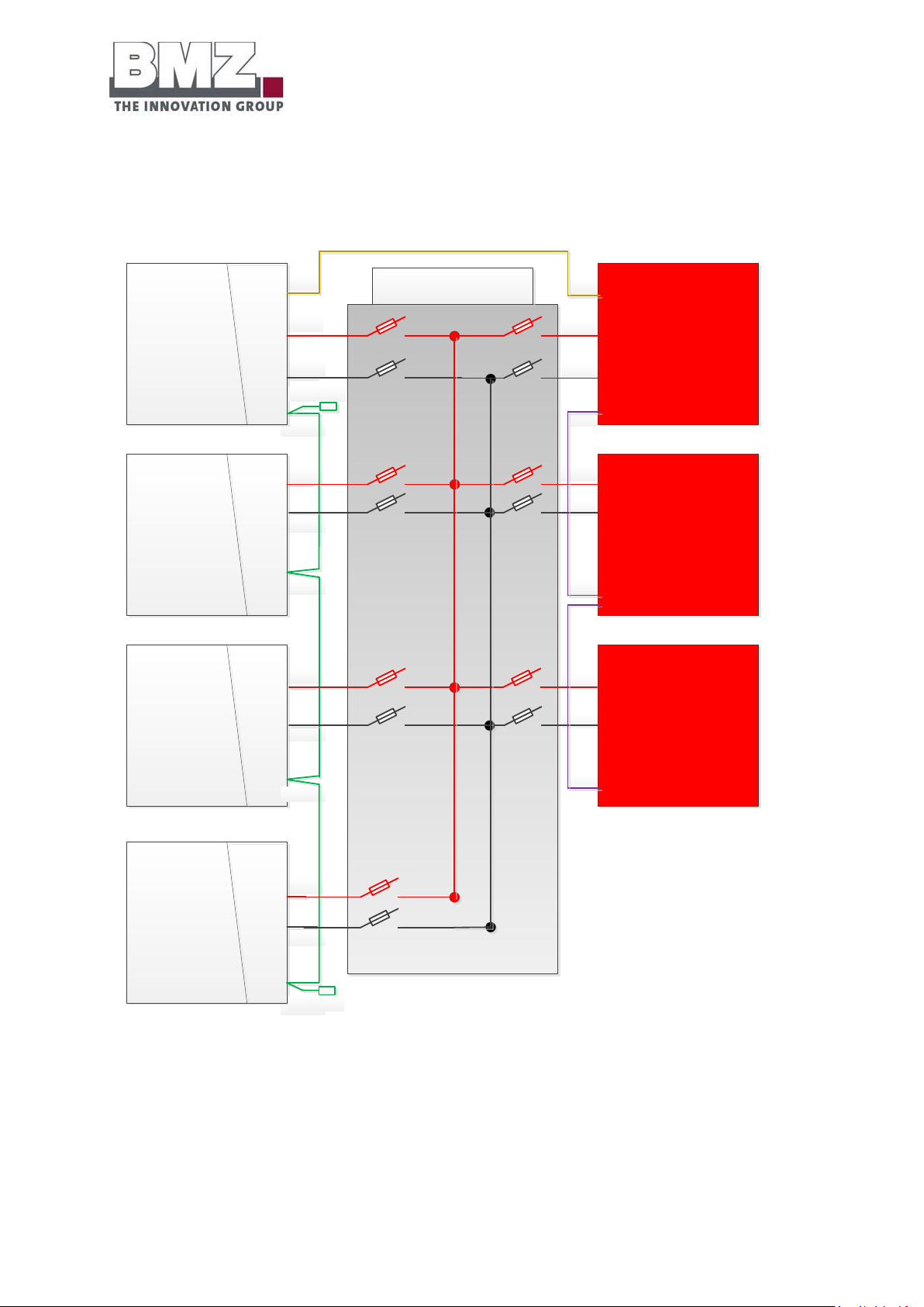
Installation, assembly and commissioning
for the first time
Version 1.1
Page 72 of 113
4.8.5 3-phase operation of a SMA Sunny Island inverter on 4 ESS batteries
CAN
Intern
SYNC
MINUS
PLUS
SYNC
SYNC
MINUS
PLUS
CAN
MINUS
PLUS
MINUS
PLUS
MINUS
PLUS
Intern
PLUS
MINUS
BMZ ESS Battery 1
battery mode „MASTER“
Device adress „1"
SMA Sunny Island
Inverter 1
Inverter „MASTER“
BMZ ESS Battery 2
battery mode „SLAVE“
Device adress „2"
BMZ ESS Battery 3
battery mode „SLAVE“
Device adress „3"
SMA Sunny Island
Inverter 2
SMA Sunny Island
Inverter 3
BAT BREAKER 6er
RS485 terminating
resistor
Intern
PLUS
MINUS
BMZ ESS Battery 4
battery mode „SLAVE“
Device adress „4"
RS485 terminating
resistor
Intern
Figure 4-22: 3-phase operation on 4 ESS batteries
Page 73

Installation, assembly and commissioning
for the first time
Version 1.1
Page 73 of 113
4.8.6 3-phase operation of a SMA Sunny Island inverter on 5 ESS batteries
CAN
Intern
SYNC
MINUS
PLUS
SYNC
SYNC
MINUS
PLUS
CAN
MINUS
PLUS
MINUS
PLUS
MINUS
PLUS
Intern
PLUS
MINUS
BMZ ESS Battery 1
battery mode „MASTER“
Device adress „1"
SMA Sunny Island
Inverter 1
Inverter „MASTER“
BMZ ESS Battery 2
battery mode „SLAVE“
Device adress „2"
BMZ ESS Battery 3
battery mode „SLAVE“
Device adress „3"
SMA Sunny Island
Inverter 2
SMA Sunny Island
Inverter 3
BAT BREAKER 6er
RS485 terminating
resistor
Intern
MINUS
PLUS
Intern
PLUS
MINUS
BMZ ESS Battery 4
battery mode „SLAVE“
Device adress „4"
BMZ ESS Battery 5
battery mode „SLAVE“
Device adress „5"
RS485 terminating
resistor
Intern
Figure 4-23: 3-phase operation on 5 ESS batteries
Page 74

Installation, assembly and commissioning
for the first time
Version 1.1
Page 74 of 113
4.8.7 3-phase operation of a SMA Sunny Island inverter on 6 ESS batteries
CAN
Intern
SYNC
MINUS
PLUS
SYNC
SYNC
MINUS
PLUS
CAN
MINUS
PLUS
MINUS
PLUS
MINUS
PLUS
Intern
PLUS
MINUS
BMZ ESS Battery 1
battery mode „MASTER“
Device adress „1"
SMA Sunny Island
Inverter 1
Inverter „MASTER“
BMZ ESS Battery 2
battery mode „SLAVE“
Device adress „2"
BMZ ESS Battery 3
battery mode „SLAVE“
Device adress „3"
SMA Sunny Island
Inverter 2
SMA Sunny Island
Inverter 3
BAT BREAKER 6er
RS485 terminating
resistor
Intern
Intern
MINUS
PLUS
MINUS
PLUS
Intern
PLUS
MINUS
BMZ ESS Battery 4
battery mode „SLAVE“
Device adress „4"
BMZ ESS Battery 5
battery mode „SLAVE“
Device adress „5"
BMZ ESS Battery 6
battery mode „SLAVE“
Device adress „6"
RS485 terminating
resistor
Intern
Figure 4-24: 3-phase operation on 6 ESS batteries
Page 75

Installation, assembly and commissioning
for the first time
Version 1.1
Page 75 of 113
4.9 Configuration of the ESS battery
4.9.1 System structure
- In a complete system of batteries connected in parallel, configure one battery as a “master”.
- In a complete system of batteries connected in parallel, configure all other batteries as “slave”.
- You can connect up to 6 batteries with each other in parallel.
4.9.2 Addressing the batteries
- Configure each battery with an unambiguous and unique address.
Numbers 1 to 12 are available.
Each battery must have a different bus address (device address).
4.10 Definition of the battery mode during commissioning and parameter
configuration
Figure 4-25: representation of the BMZ ESS service tool
4.10.1 Single:
This the delivery status of every BMZ ESS 7.0 battery ex-works.
The mode is used for the status: 1 BMZ ESS 7.0 battery operated at one SMA Sunny Island inverter.
4.10.2 Master:
This is the status of a BMZ ESS 7.0 battery in a group of multiple BMZ ESS 7.0 batteries connected in
parallel.
Important: Only one battery may be configured as a master.
The mode is used for the status: multiple BMZ ESS 7.0 batteries are operated at one or more SMA
Sunny Island inverters.
Page 76

Installation, assembly and commissioning
for the first time
Version 1.1
Page 76 of 113
4.10.3 Slave:
This is the status of multiple BMZ ESS 7.0 batteries in a group of multiple BMZ ESS 7.0 batteries
connected in parallel.
Important: Each battery, except the master battery, must be configured as a slave battery.
The mode is used for the status: multiple BMZ ESS 7.0 batteries are operated at one or more SMA
Sunny Island inverters.
Page 77
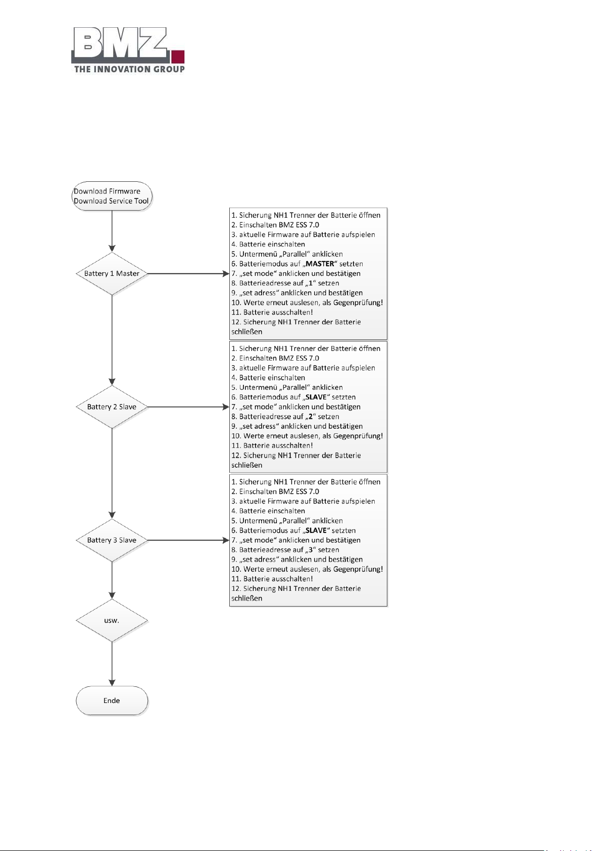
Installation, assembly and commissioning
for the first time
Version 1.1
Page 77 of 113
4.11 Work step sequence to configure the parameters of batteries
Execute the following steps to configure the parameters of batteries for a system comprising ESS batteries
connected in parallel.
Figure 4-26: representation of the work sequence to configure the parameters of a BMZ ESS battery
Page 78
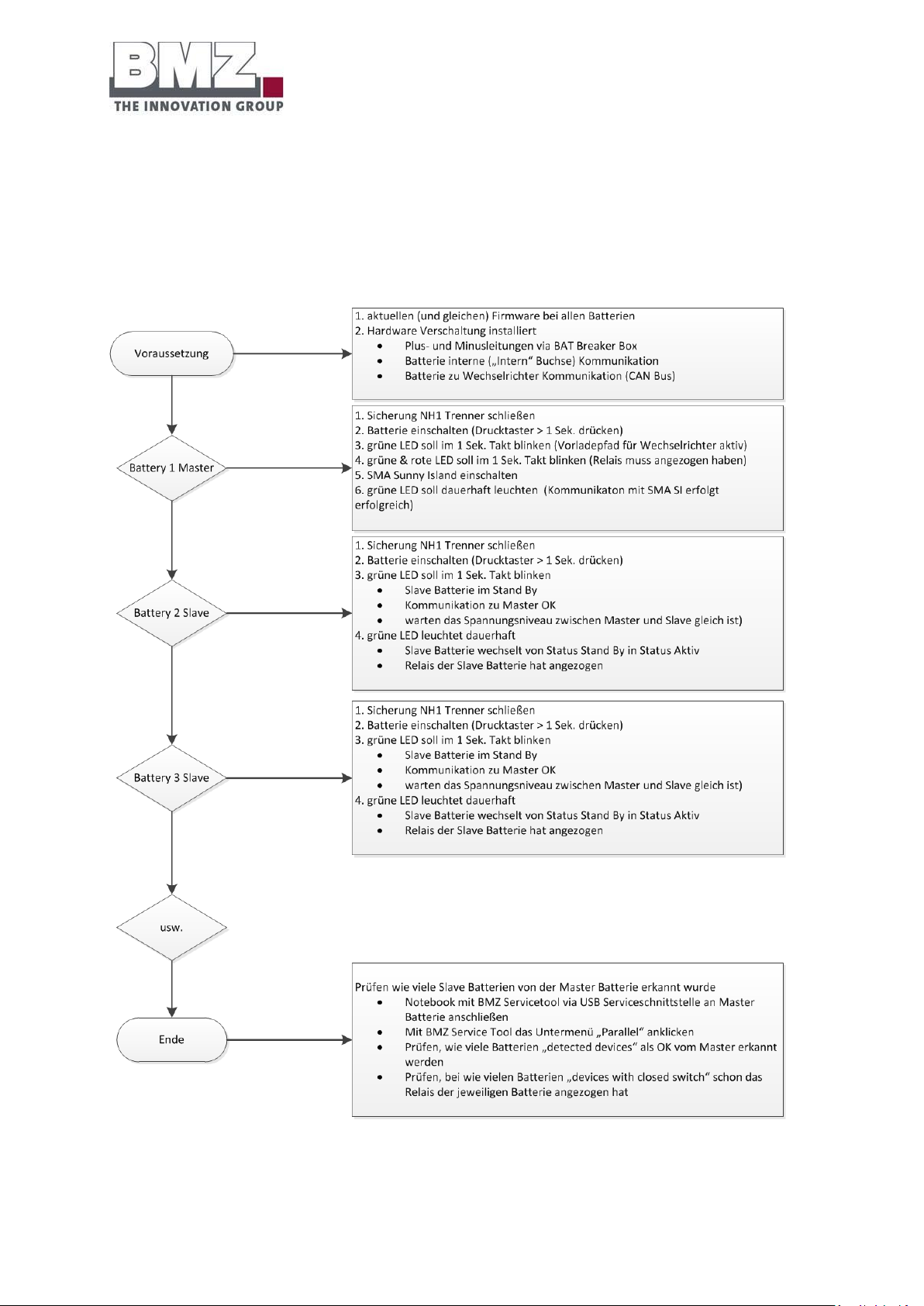
Installation, assembly and commissioning
for the first time
Version 1.1
Page 78 of 113
4.12 Work step sequence to commission the batteries
Execute the following steps to commission a system comprising ESS batteries connected in parallel.
Figure 4-27: representation of the work sequence to commission a BMZ ESS battery
Page 79
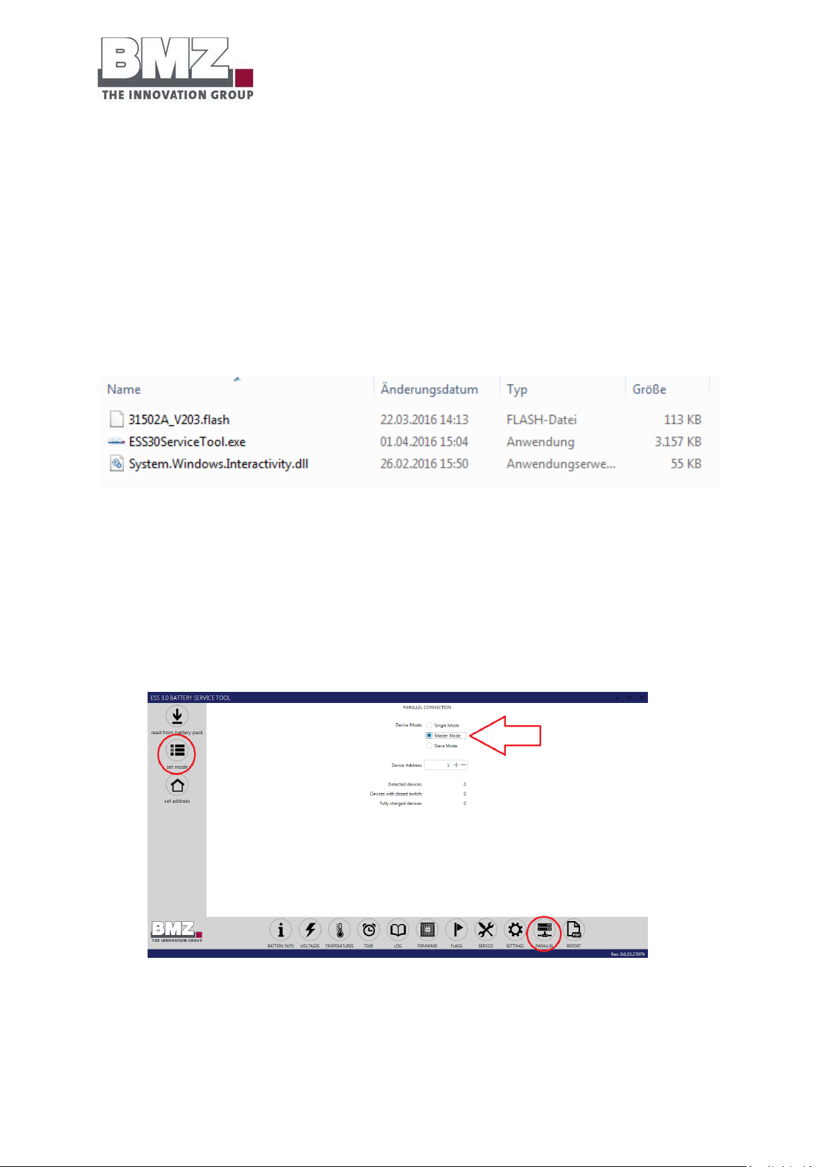
Installation, assembly and commissioning
for the first time
Version 1.1
Page 79 of 113
4.13 Configuration of firmware for parallel mode
Use the BMZ service tool to configure the battery using the USB service port.
The following files must be available to configure the battery parameters:
1. ESS30ServiceTool.exe (example: current service tool V0.0.26)
2. System.Windows.Interactivity.dll
3. Optional for firmware update: 31502A_V205.flash (example: current firmware V2.05)
Important: All three files must be in the same folder.
Figure 4-28: file structure of the BMZ ESS service tool
4.13.1 Setting the master battery mode
In a group of multiple BMZ ESS 7.0 batteries connected in parallel, configure one battery as a master.
Important:
1. Set the “Master” mode and configure the battery parameters by clicking on “set mode”.
2. In a group of multiple BMZ ESS 7.0 batteries connected in parallel, only one battery may be
configured as a master.
Figure 4-29: representation of configuration of the parameters of a BMZ ESS battery
3. IMPORTANT: Configure the parameters of the battery with the maximum voltage level and the
maximum charge status as the master battery.
Page 80
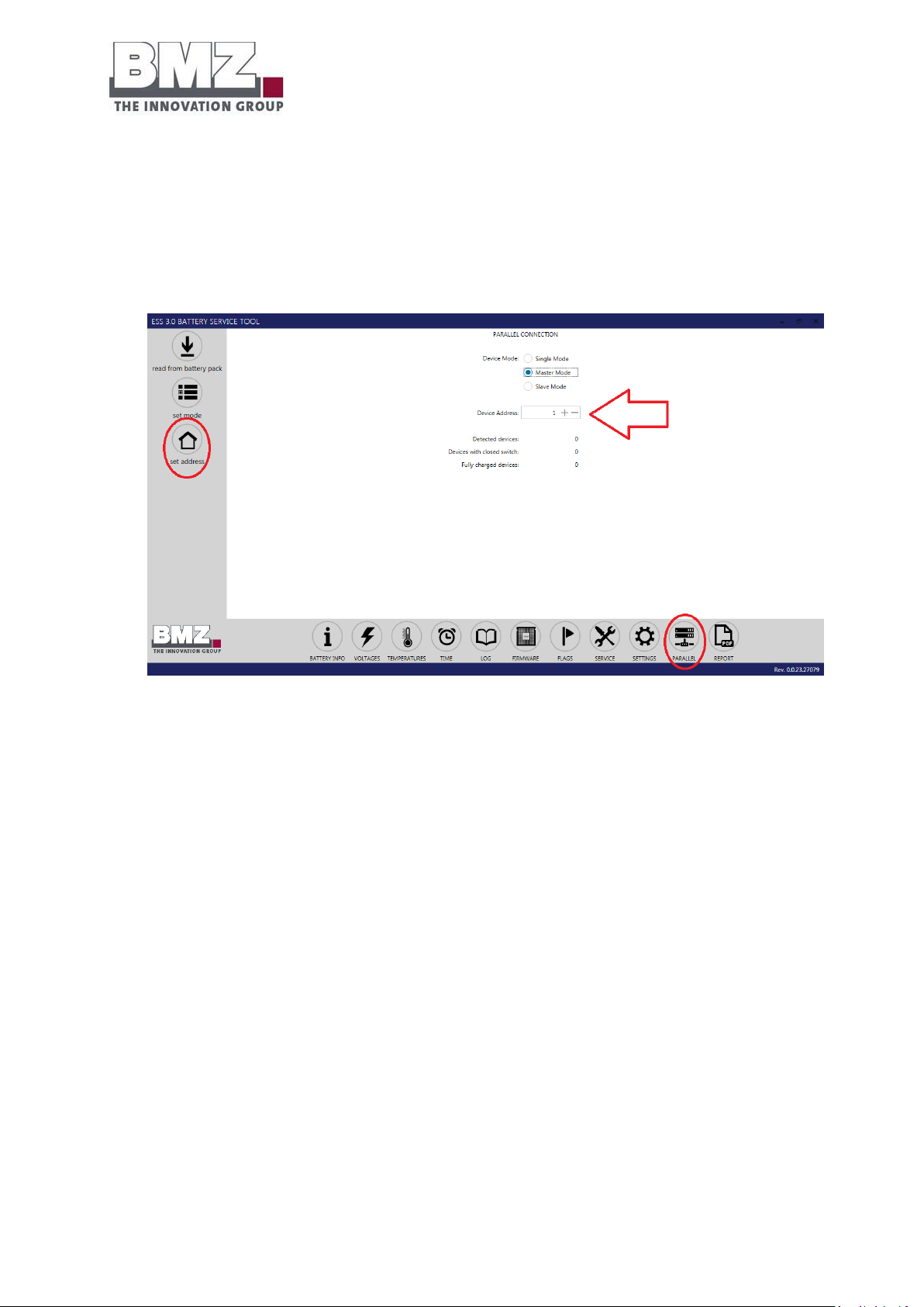
Installation, assembly and commissioning
for the first time
Version 1.1
Page 80 of 113
4.13.2 Setting the master battery address
Address 0 is the default address.
Each battery connected in parallel must have an unambiguous and unique address (device address).
The master and slave batteries function only with the addresses configured with numbers from 1 to
12.
Figure 4-30: representation of configuration of the parameters of a BMZ ESS battery
Important:
1. Set the “address” (device address) to “1” and configure the battery parameters by clicking on “set
address”.
2. In a group of multiple BMZ ESS 7.0 batteries connected in parallel, only one battery may have the
address “1”.
Page 81
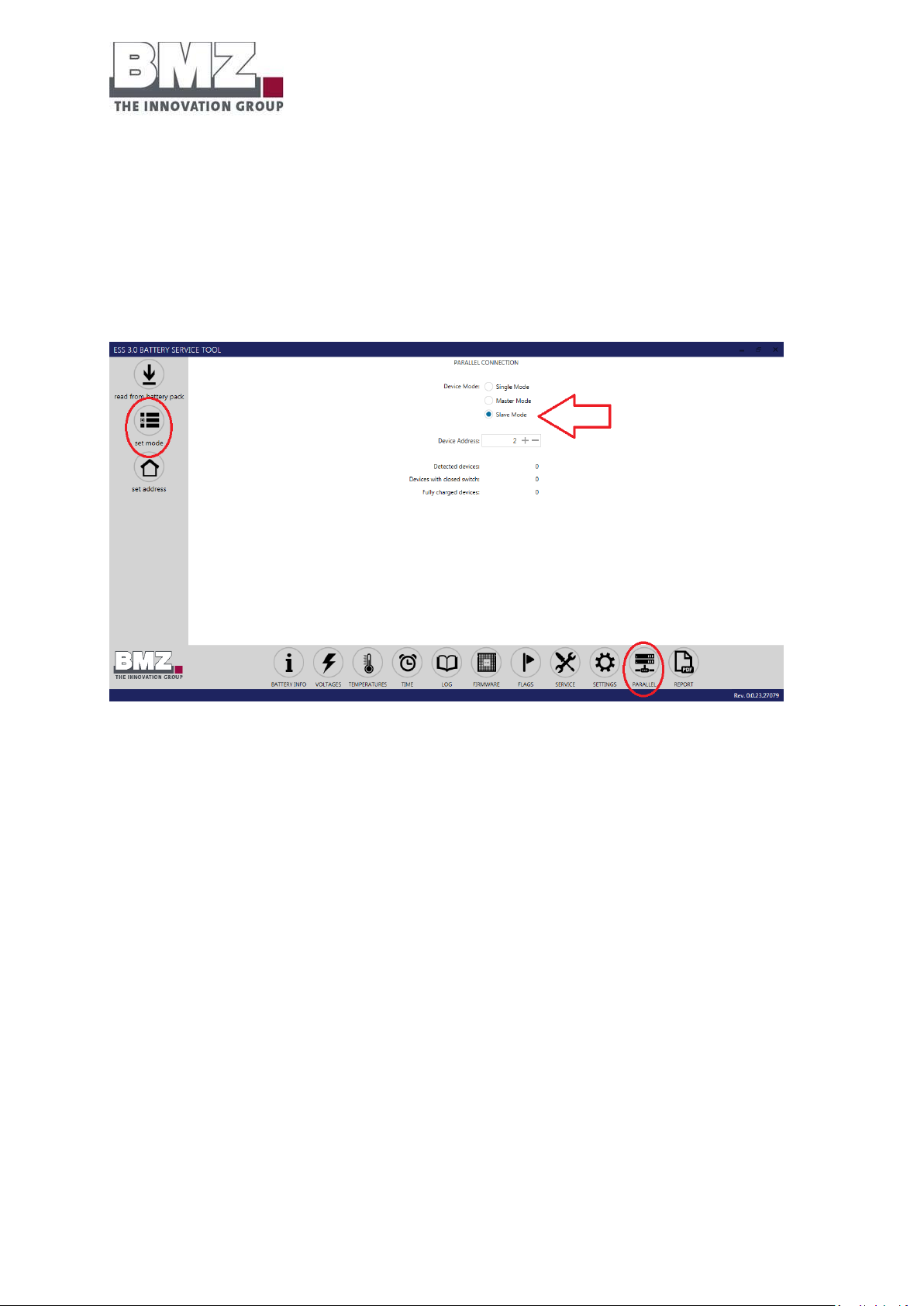
Installation, assembly and commissioning
for the first time
Version 1.1
Page 81 of 113
4.13.3 Setting the slave battery mode
In a group of multiple BMZ ESS 7.0 batteries connected in parallel, configure all batteries, except the master,
as slaves.
Important:
1. Set the “Slave” mode and configure the battery parameters by clicking on “set mode”.
Figure 4-31: representation of configuration of the parameters of a BMZ ESS battery
Page 82
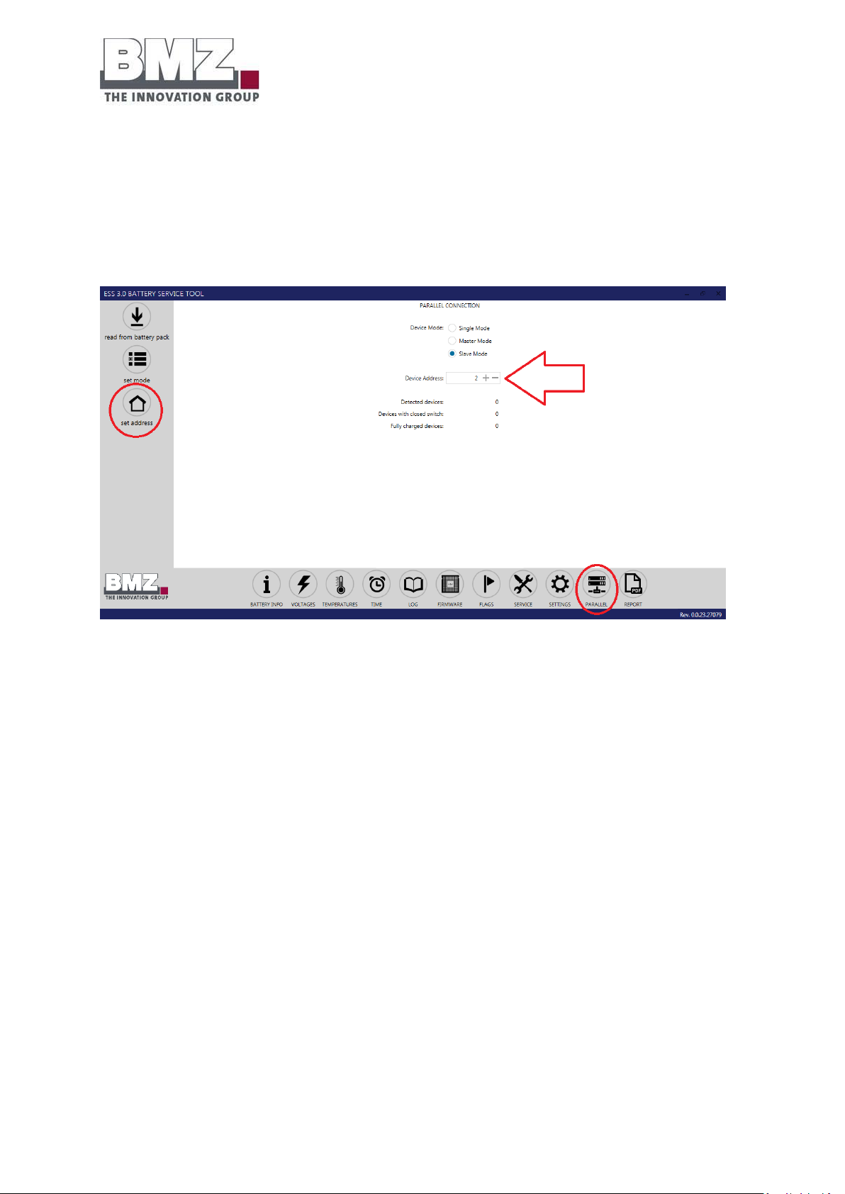
Installation, assembly and commissioning
for the first time
Version 1.1
Page 82 of 113
4.13.4 Setting the slave battery address
Address 0 is the default address.
Each battery connected in parallel must have an unambiguous and unique address (device address).
The master and slave batteries function only with the addresses configured with numbers from 1 to
12.
Figure 4-32: representation of configuration of the parameters of a BMZ ESS battery
Important:
1. Set the “address” (device address) to “2” and configure the battery parameters by clicking on “set
address”.
2. In a group of multiple BMZ ESS 7.0 batteries connected in parallel, only one battery may have the
address “2”.
3. Configure a unique and unambiguous address (device address) for all other slave batteries.
Page 83
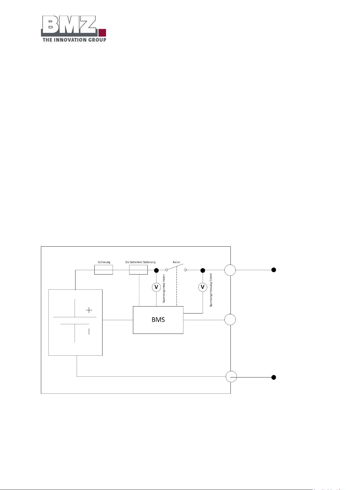
Installation, assembly and commissioning
for the first time
Version 1.1
Page 83 of 113
4.14 Commissioning the parallel connection of multiple batteries
4.14.1 Switch-on sequence
1. At the time of commissioning, first switch on the master battery.
2. Check whether the main relay of the master battery is switched on
-> Check via LED flashing speed (see section 5.1) or BMZ service tool (see section 4.4)
3. If the main relay of the master battery is closed, you can now switch on other slave batteries.
4.14.2 Stand-by mode of a slave battery:
When you switch on the slave batteries, the batteries are automatically in the stand-by mode. (The stand-by
mode is indicated by a green flashing LED) Only when the master sends a switching signal for the main relay
of the slave battery, the main relay of the slave battery is switched on. The slave battery can be used the
complete battery system only after this.
4.14.3 Switch-on criterion of the slave battery:
Each battery compares the internal battery voltage with the externally applied voltage through a
measurement.
Figure 4-33: block circuit diagram of the BMZ ESS slave battery
If the voltage automatically measured by the battery at the master battery differs from the slave battery
voltage by less than +/-100 mV, the slave battery switches off automatically.
Page 84

Installation, assembly and commissioning
for the first time
Version 1.1
Page 84 of 113
Important:
To ensure that all slave batteries are activated from the master battery in case of a different voltage level
for different batteries, change the charge status of the master battery by charging and discharging using the
inverter.
Within a full cycle (i.e. the battery is completely charged once and completely discharged once), the master
battery scans all slave batteries in the stand-by mode and switches them off one by one.
This process may take a few hours depending on the available PV energy or loads in the company network.
4.14.4 Example 1:
6 batteries connected in parallel with different charge statuses:
- The master battery is switched on and the main relay is switched on
- 2 slave batteries are switched on and the main relay is switched on
- 3 slave batteries are switched on and the main relay is NOT switched on
Figure 4-34: representation of example 1, different SOC of BMZ ESS batteries connected in parallel
4.14.5 Example 2:
6 batteries connected in parallel with different charge statuses:
- The master battery is switched on and the main relay is switched on
- 4 slave batteries are switched on and the main relay is switched on
- 1 slave battery is switched on and the main relay is NOT switched on
Page 85
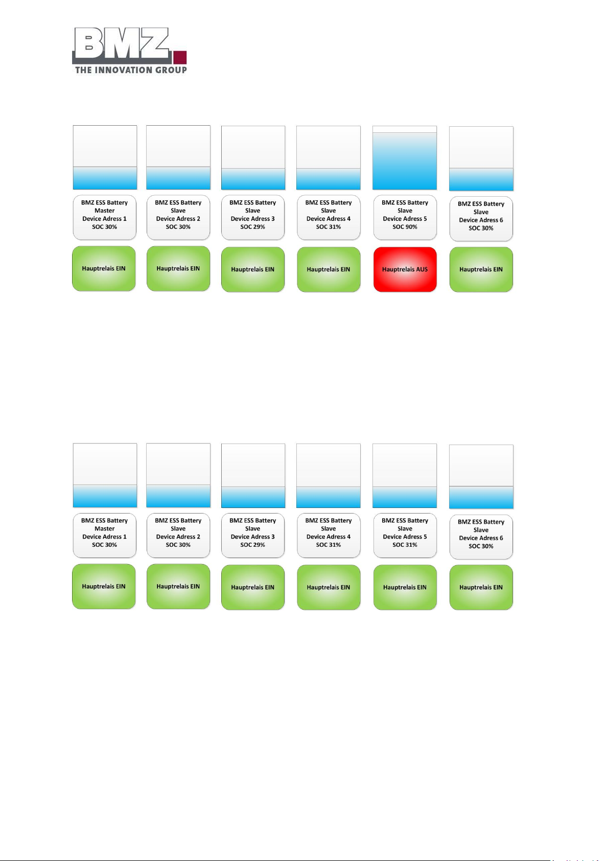
Installation, assembly and commissioning
for the first time
Version 1.1
Page 85 of 113
Figure 4-35: representation of example 2, different SOC of BMZ ESS batteries connected in parallel
4.14.6 Example 3:
6 batteries connected in parallel with different charge statuses:
- The master battery is switched on and the main relay is switched on
- 5 slave batteries are switched on and the main relay is switched on
Figure 4-36: representation of example 3, different SOC of BMZ ESS batteries connected in parallel
Page 86

Installation, assembly and commissioning
for the first time
Version 1.1
Page 86 of 113
4.15 Checking the parallel connection of multiple batteries
4.15.1 Check the number of connected (detected) batteries
o Connect the notebook to the master battery.
o The “Detected devices” number shows the number of batteries connected to the master (and that
are in the stand-by mode).
Figure 4-37: check the number of BMZ ESS batteries connected in parallel
Other test criterion: The LED of a battery in the stand-by mode flashes green.
Page 87
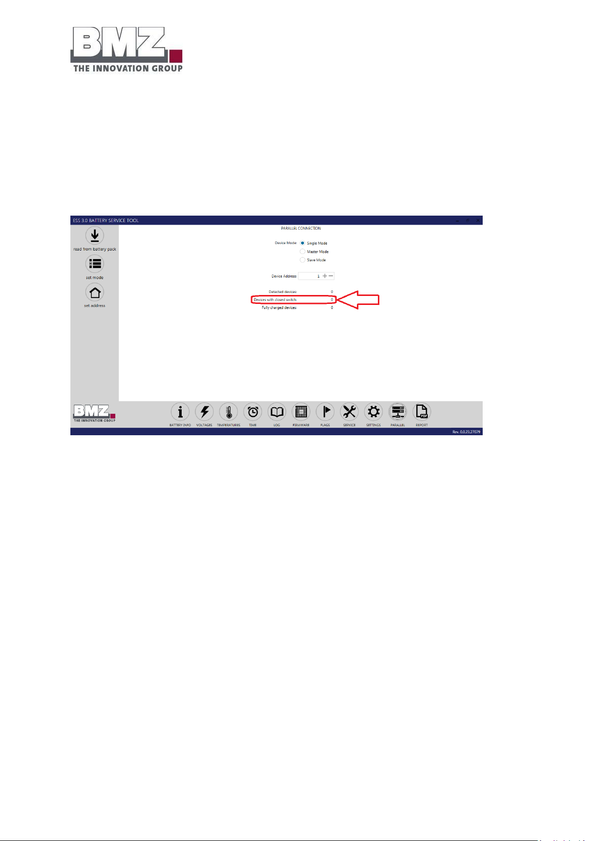
Installation, assembly and commissioning
for the first time
Version 1.1
Page 87 of 113
4.15.2 Check the number of batteries for which the main relay is closed
o Connect the notebook to the master battery.
o The “Devices with closed switch” number shows the number of batteries connected to the master
for which the main relay is closed.
o These batteries are connected in parallel to the master battery and can thus be used in the
complete system (charging and discharging).
Figure 4-38: check the number of BMZ ESS batteries connected in parallel
Other test criterion: The LED of a battery in the parallel mode (active) continuously lights up in green.
4.16 Adding new batteries
BMZ allows subsequent extensions of the battery system until six months after the first installation.
1) Configure a new battery as a slave
2) Disconnect the NH isolator of the output rail
3) Disconnect the NH isolator of the battery
4) Connect the power cable of the slave battery to the output rail.
5) If the new slave battery is switched on, switch it off by pressing the button for 10 seconds (LEDs
must be off)
6) Connect the NH isolator of the battery
7) Connect the NH isolator of the output rail
8) Switch on the slave battery using the button (press the button for > 1 second, LEDs flash)
After adding a new battery, you may still need to deal with the equalising currents. This may lead to the
adjustment of the capacity even if no current flows from or to the inverter.
Page 88
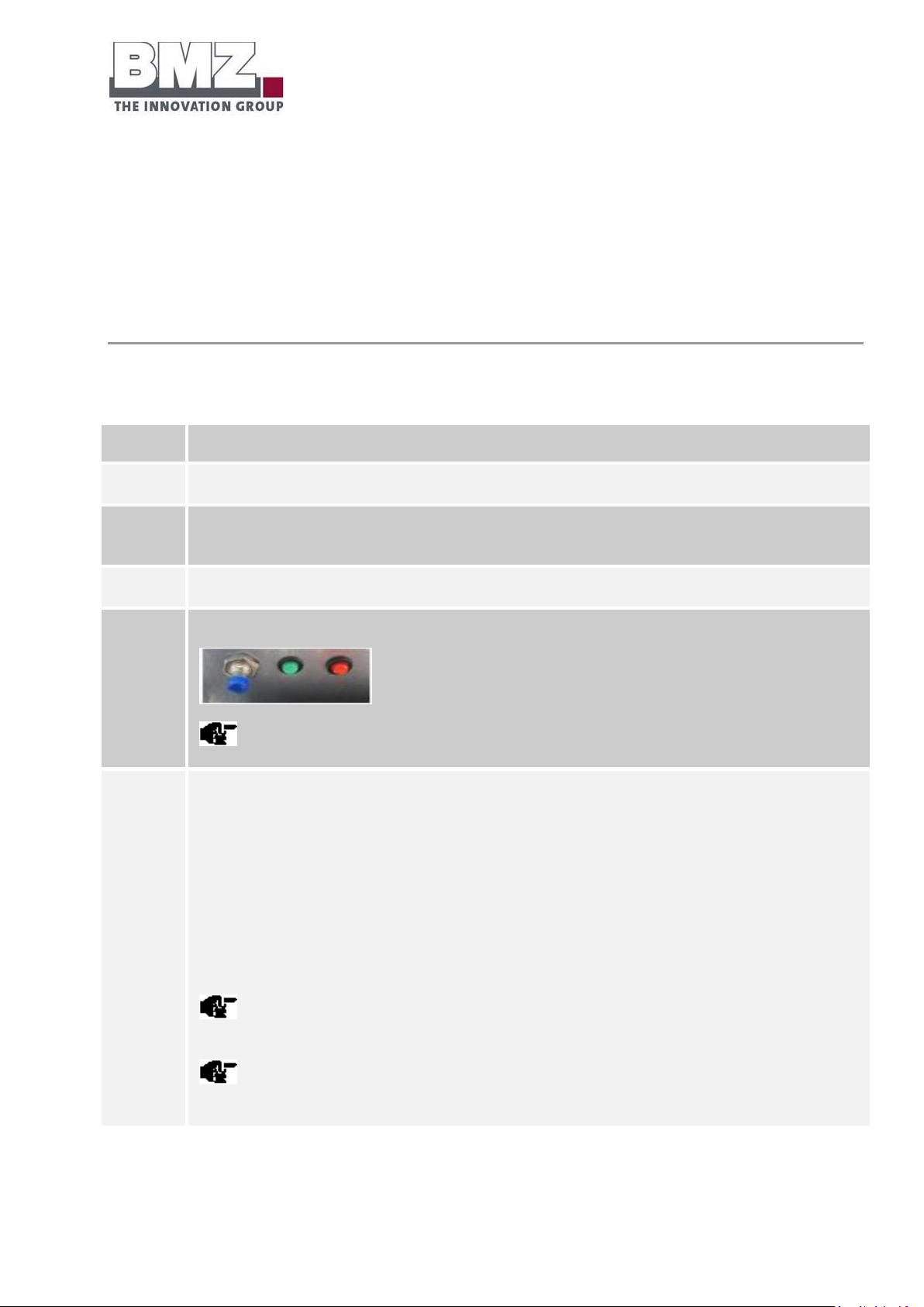
Installation, assembly and commissioning
for the first time
Version 1.1
Page 88 of 113
4.17 Checking the connections of parallel battery systems
Step
Description
1
Open the screws on the service flat using a PH2 screwdriver.
2
Check whether the NH isolator is equipped with correct (see section 4.5) NH fuses and put into operation
correctly.
3
Check the connections of the DC power cable (+, -) and the CAN communication cable of the battery inverter.
4
Actuate the push button through a short (longer than 1 second) push.
A clicking sound must be heard.
5
Check the LED status of the battery storage system.
The green LED flashes quickly (every 150 msec): The pre-charging path is activated and charges the
capacitors of the inverter. (The pre-charging time depends on the type and number of connected inverters.
The pre-charging time can take from 30 seconds to 2 minutes)
For slave batteries: The green LED flashes slowly (every 1 second): The battery is active and waits for the
switch-on signal of the master battery.
Both LEDs flashes slowly (every 1 second): The battery is active and waits for communication through the
inverter.
The battery switches off automatically after 20 minutes if there is no communication between the battery
and the inverter.
Additional information regarding the LED flashing patterns is given in the Pilot lamps section,
page 95.
Check the connections as per the exact specifications in the installation check list given in the annexe.
4.17.1 Switching the battery storage system on and off
The battery storage system and the inverter must be correctly installed before they can be put into
operation.
Switch on the battery storage system using a switch
Proceed as follows to start the battery storage system:
Page 89
Installation, assembly and commissioning
for the first time
Version 1.1
Page 89 of 113
6
Switch on the battery inverter.
The green LED lights up continuously
If there is no communication between the battery storage system and the inverter, the battery switches
off automatically after 20 minutes to avoid erroneous operating modes. Both LEDs flash in a one-second cycle if
there is no communication.
7
Important: (see chapter 4.14.1)
At the time of commissioning of batteries connected in parallel, first switch on the master
battery.
1. Check whether the main relay of the master battery is switched on
-> Check via LED flashing speed (see section 5.1) or BMZ service tool (see section 5.2)
2. If the main relay of the master battery is closed, you can now switch on other slave
batteries.
If the switch-on sequence for batteries connected in parallel is not followed, it may happen
that none of the batteries allow switching off the main relay.
Step
Description
1
The external voltage source can be used to switch on the system only if it was not switched off using the push
button (press the push button longer than 10 seconds at a stretch).
2
Connect an external voltage source greater than 36 VDC.
3
The battery detects the external voltage source automatically and switches the operating mode from inactive to
active.
4
If it is switched on in an unauthorised manner, the green LED flashes quickly (100 ms flash cycle)
You must now start the battery using a normal switch-on sequence (by pressing the push button longer than 1
second).
Switch on the battery storage system using an external voltage source
Proceed as follows to start the battery storage system:
Switch off the battery storage system using a push button
Proceed as follows to switch off the battery storage system:
Page 90
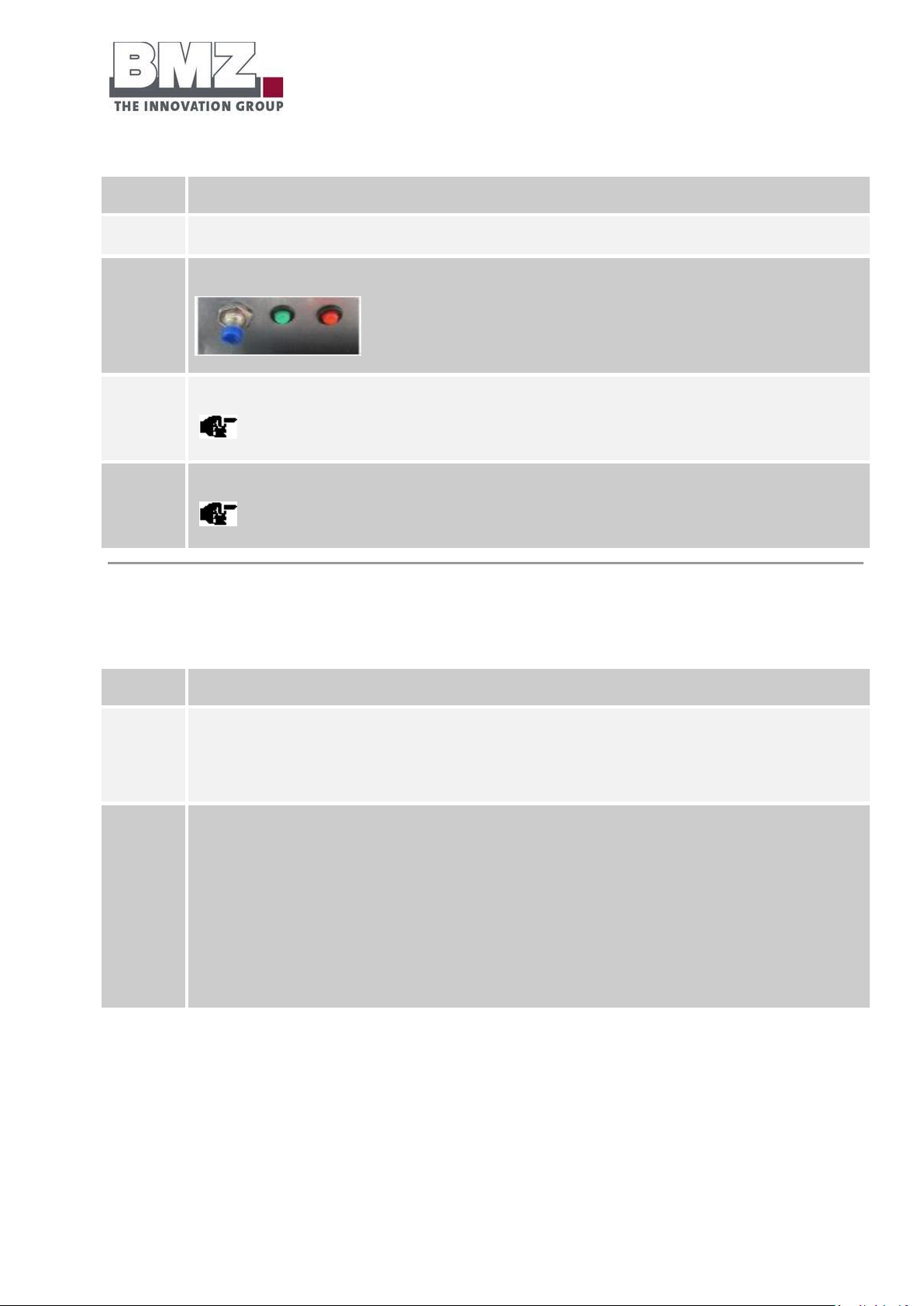
Installation, assembly and commissioning
for the first time
Version 1.1
Page 90 of 113
Step
Description
1
Open the screws on the service flat using a PH2 screwdriver.
2
Keep the switch-on button pressed for at least 10 seconds.
3
After approximately 8 seconds, both LEDs start flashing quickly (100 ms flash cycle).
Keep the button pressed for 2 more seconds.
4
The LEDs switch off. The battery storage system is now switched off.
A clicking sound must be heard.
Switch off the battery storage system using time
Step
Description
1
If an external source (e.g. the battery inverter) does not detect a CAN communication of the battery, the battery
switches off automatically after 20 minutes.
2
Optional:
If the battery is installed in parallel mode, the battery defined as master first switches off after 20 minutes
without CAN communication of the external source.
The slave battery then switches off after 20 minutes.
If a master or a slave battery is now switched on in the parallel mode, all batteries in the complete system are
switched on since they are activated by the pre-charging voltage of the battery that is switched on first (see
Switching on the battery storage system using an external voltage source
The battery switches off automatically after a defined time of 20 minutes when the battery does not detect
any CAN communication externally.
4.17.1 Configuring the parameters of the inverter
The inverter parameters must be configured for the BMZ ESS 7.0 battery in order to operate it optimally in
combination with the inverter.
See section 4.18
Page 91
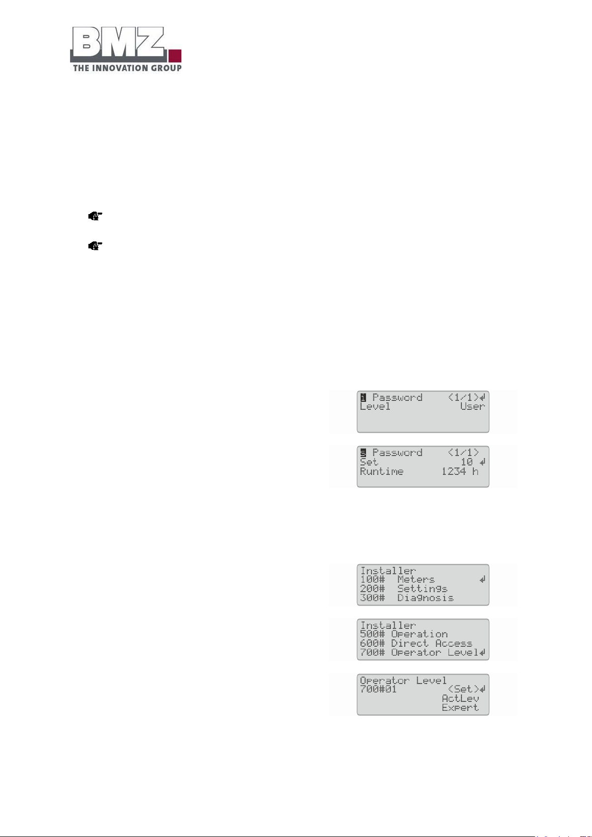
Installation, assembly and commissioning
for the first time
Version 1.1
Page 91 of 113
1. Enter the following values in the quick configuration guide during the basic configuration of the
Sunny Island inverter (see the documentation of the system):
Battery type BatTyp: LiIon_Ext-BMS
Battery capacity BatCpyNom: 105 Ah (C10)
2. After the basic configuration of the
Sunny remote control, turn the knob and select the
input page password (1/1).
3. Press the knob. This will take you to the input page.
4. Calculate the checksum of the Runtime operating hours. Determine the installer password.
Example: The Runtime operating hours are 1234 h. The checksum is the sum of all digits:
1 + 2 + 3 + 4 = 10
5. Select Set on the Sunny remote control and press the knob.
6. Set the determined installer password and press the knob.
The Sunny remote control is in the installer mode.
7. Select the 700# Operator Level menu and press the
knob.
8. Select the 700.01 ActLev parameter, press the knob
and set to Expert.
9. Confirm the <accept Y/N> query with Y.
4.18 Recommended parameters of the SMA Sunny Island inverter at the time
of installation:
In order to ensure the optimum working range of the battery and to optimise the quantity of storable
energy, the battery manufacturer has given the following recommendations for the parameters of the
inverter:
A detailed description of parameters is given in the operating manual of your SMA Sunny Island
inverter.
Amongst the recommended parameters, we differentiate between “On-grid” and “Off-grid”
applications.
4.18.1 On-grid application
10. Set the following parameters to the specified values only if the Sunny Island units are used in systems for
own consumption optimisation:
Page 92

Installation, assembly and commissioning
for the first time
Version 1.1
Page 92 of 113
Number
Name
Value
261.03
Season enable
No
262.01
ProtResSOC
3%
262.02
BatResSOC
2%
262.03
BUResSOC
1%
262.04
PVResSOC
5%
262.05
MinSlfCsmpSOC
89%
Figure 4-39: SMA on-grid parameters
In order to optimise the efficiency of the battery, the battery automatically executes a learning cycle at
periodic intervals, wherein the actually usable capacity of the battery is automatically determined.
In this learning cycle, the battery must cover the SOC limits of 100% and 12% as frequently as
possible.
The learning cycle starts at 100% SOC (battery full) and ends at 12% SOC. If both incidents occur in
succession and, in the meantime, the energy is not charged more than 20% SOC, then the learning
cycle is evaluated as “successfully executed”.
The higher the frequency of execution of this learning cycle, the more precise is the SOC calculation.
The higher the frequency of execution of this learning cycle, the more the energy that the battery can
save and transfer.
Page 93

Installation, assembly and commissioning
for the first time
Version 1.1
Page 93 of 113
Number
Name
Value
Diesel generator start
12% SOC
Load shedding of relay
10% SOC
Bat Pro 3
7% SOC
Bat Pro 2
5% SOC
Bat Pro 1
3% SOC
4.18.2 Off-grid application
In the expert mode, set the following parameters when installing the inverter:
Figure 4-40: SMA off-grid parameters
In order to optimise the efficiency of the battery, the battery automatically executes a learning cycle at
periodic intervals, wherein the actually usable capacity of the battery is automatically determined.
In this learning cycle, the battery must cover the SOC limits of 100% and 12% as frequently as
possible.
The learning cycle starts at 100% SOC (battery full) and ends at 12% SOC. If both incidents occur in
succession and, in the meantime, the energy is not charged more than 20% SOC, then the learning
cycle is evaluated as “successfully executed”.
The higher the frequency of execution of this learning cycle, the more precise is the SOC calculation.
The higher the frequency of execution of this learning cycle, the more the energy that the battery can
save and transfer.
Page 94

Operation and service software
Version 1.1
Page 94 of 113
5 Operation and service software
Colour pattern
Flashing frequency
Function
OFF
OFF
The battery is switched off
Green + Red
Continuously lit up
Service mode (a PC is connected)
Quick flashing
(100msec)
The battery is in error mode
The relay is tripped and cannot be switched on
For example, the temperature is too high
For example, the temperature is too low
Please contact the BMZ Service immediately (see section (7))
Slowly flashing
(1sec)
The battery is switched on, but no communication with the inverter.
(Countdown of 20 minutes until the battery is switched off)
Green
Continuously lit up
The battery is switched on (normal mode)
The relay is pulled
The inverter is fed via Softstart (pre-charging branch)
No error
Slowly flashing
(1sec)
Pre-charging is activated. (Normal mode)
The pre-charging path for charging the capacitors of the inverter is
activated
The relay is still not pulled
Slowly flashing
(1sec)
SLAVE battery (normal mode)
The pre-charging path for charging the capacitors of the inverter is
activated
The relay is still not pulled (master not active)
The battery is in stand-by mode and switches off automatically as
soon as the master is activated.
Red
Quick flashing
(100ms)
The battery is in error mode
The relay is tripped and cannot be switched on
The 2nd protection switch element (Pyrofuse) has tripped
Please contact the BMZ Service immediately (see section (7))
General safety instructions
Please follow the safety instructions in the Safety section, page 13.
5.1 Pilot lamps (LED)
5.1.1 LED indicators on the battery module
The pilot lamps on the battery module indicate the possible statuses and incidents in the operation of the
battery storage system.
Figure 5-1: pilot lamps table (LED)
Page 95
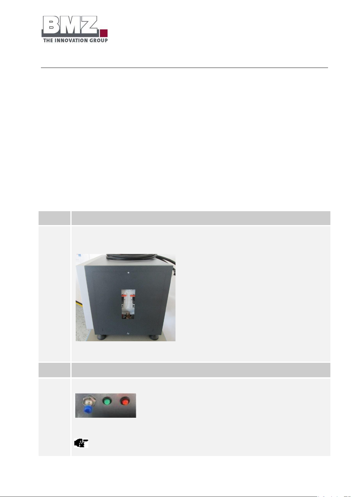
Operation and service software
Version 1.1
Page 95 of 113
Step
Description
1
Open the screws on the service flat using a PH2 screwdriver.
Loosen and remove the upper fillister-head screw of the lateral service flap.
Figure 5-2: side view of BMZ ESS, service flap
2
Now push the flap of the side panel upwards to remove it.
3
Switch off the battery system.
Figure 5-3: push button with LEDs
Both LEDs must not light up.
5.1.2 Charging status indicator
The charging status indication is given using the communication line via the inverter.
5.2 Connection of the notebook for servicing
5.2.1 USB port
Each rechargeable battery set has a USB port.
The installer can use this port to execute the following steps:
Update (firmware)
Read error memory
Proceed as follows to read the battery storage system via the USB port:
Page 96
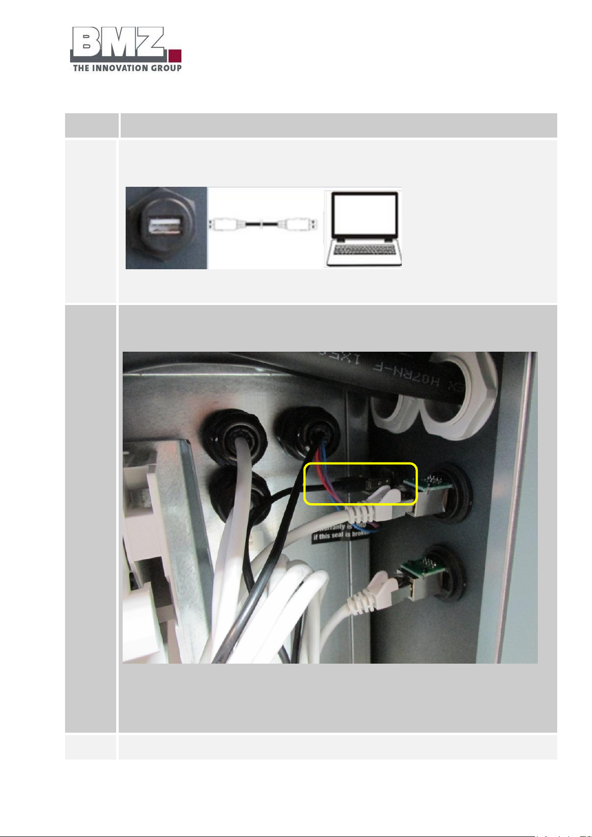
Operation and service software
Version 1.1
Page 96 of 113
4
Pull out the NH fuses of the NH isolator and remove the safety bracket and fuses from the isolator.
5
Connect the notebook to the battery storage system.
Connect the USB A cable of the notebook to the USB A port of the battery storage system.
Figure 5-4: USB communication
5a
This step is applicable if there is no communication between the battery storage system and the notebook.
Connect the USB cable directly from the battery storage system.
Figure 5-5: USB port of BMZ ESS battery, inner side of housing
Loosen the cable binder of the USB cable carefully using a side cutter and pull the USB plug internally from the
socket (rear wall).
6
Connect the notebook with the battery storage system using the USB cable.
Page 97

Operation and service software
Version 1.1
Page 97 of 113
The notebook must not be connected with the AC grid via the charging cable.
7
Switch on the battery storage system using the push button.
Figure 5-6: push button and LEDs
8
The service software can now be installed and started.
Page 98

Operation and service software
Version 1.1
Page 98 of 113
5.2.2 Service software
The software is easy to operate and works with all commonly used Windows versions.
The following functions are possible
Read battery status (cell voltages, temperatures)
Firmware update
Configuration of the battery for parallel mode
Download log files (for sending to the Service Department via email)
Prepare PDF report (actual status of the battery)
For more information regarding the service software, please refer to the operating manual of the BMZ
service tool. It is a separate document.
Please contact BMZ GmbH for this purpose.
Page 99

Fault/damage event
Version 1.1
Page 99 of 113
6 Fault/damage event
6.1 Fault indicators
6.1.1 Fault indicators of pilot lamps
Fault indicators of pilot lamps
Two LEDs are provided on the battery storage system.
In case of errors in the battery storage system, they either individually flash in red or flash together in red
and green.
Detailed information regarding the flashing pattern in given in the Pilot lamps section (page 94).
Fault indicators of the battery via the inverter
Detailed information regarding error codes displayed by the inverter are given in the corresponding section
of the operating manual of the inverter manufacturer.
Page 100
Fault/damage event
Version 1.1
Page 100 of 113
6.2 Actions to be taken in case of a damage
WARNING
Possible risk to life due to leaking electrolytes.
If you do not observe the following behavioural instructions, they may
cause material damage and personal injuries; BMZ GmbH shall not bear
any liability in such a case.
Switch off the battery storage system if it is possible without any
risk.
Ensure adequate ventilation outside.
Prevent these hazardous situations. Otherwise, they may lead to
deaths or serious injuries.
General information
If the battery storage system is used for the intended purposes, lithium ion batteries do not pose any risk.
If cells and the housing are damaged, there is a risk of contact with electrolytes.
Please follow the safety data sheet of the BSW: “Use of stationary lithium solar power accumulators”
under www.solarwirtschaft.de
6.2.1 First aid measures
If the battery storage system and the battery modules installed in it are damaged, please initiate the
following first aid measures:
Contact with skin and eyes:
Skin irritations may occur. Wash the skin thoroughly with soap and water.
Irritations in eyes may occur. Wash eyes thoroughly with water for 15 minutes and then visit a
doctor.
Respiratory tracts:
Generated gases may damage respiratory tracts.
Ventilate immediately or go in fresh air; in worst cases, call a doctor immediately.
Burns:
 Loading...