

Page 1

Contents
Information Provided by:
Owner's Manual
for Vehicle
A-Z
The Ultimate
Driving Machine®
THE BMW X1.
WNER'S MANUAL.
O
Online Edition for Part no. 01 40 2 954 052 - II/15
Page 2

Information Provided by:
Page 3

X1
Information Provided by:
Owner's Manual for Vehicle
Thank you for choosing a BMW.
The more familiar you are with your vehicle, the better control
you will have on the road. We therefore strongly suggest:
Read this Owner's Manual before starting off in your new BMW.
It contains important information on vehicle operation that will
help you make full use of the technical features available in your
BMW. The manual also contains information designed to en‐
hance operating reliability and road safety, and to contribute to
maintaining the value of your BMW.
Supplementary information can be found in the additional bro‐
chures in the onboard literature.
We wish you a safe and enjoyable drive.
BMW AG
Online Edition for Part no. 01 40 2 954 052 - II/15
Page 4

© 2015 Bayerische Motoren Werke
Information Provided by:
Aktiengesellschaft
Munich, Germany
Reprinting, including excerpts, only with the written
consent of BMW AG, Munich.
deutsch II/15
Printed on environmentally friendly paper, bleached
without chlorine, suitable for recycling.
, 03 15 500
Online Edition for Part no. 01 40 2 954 052 - II/15
Page 5

ADDENDUM TO OWNER'S MANUAL
Information Provided by:
We wanted to provide you with some updates
and clarifications with respect to the printed
BMW Owner's Manual. These updates and
clarifications will supersede the materials contained in that document.
1. Where the terms “service center,” “the ser-
vice center,” “your service center,” “service
specialist,” or “service” are used in the
Owner's Manual, we wanted to clarify that
the terms refer to a BMW dealer's service
center or another service center or repair
shop that employs trained personnel that
can perform maintenance and repair work
on your vehicle in accordance with BMW
specifications.
2. Where the text of the Owner's Manual con-
tains an affirmative instruction to contact a
“service center” or “your service center,”
we wanted to clarify that BMW recommends that, if you are faced with one of the
situations addressed by that text, you contact or seek the assistance of a BMW
dealer's service center or another service
center or repair shop that employs trained
personnel that can perform maintenance
and repair work on your vehicle in accordance with BMW specifications.
While BMW of North America LLC, at no
cost to you, will pay for repairs required by
the limited warranties provided with respect
to your vehicle and for maintenance under
the Maintenance Program during the applicable warranty and maintenance coverage
periods, you are free to elect, both during
those periods and thereafter, to have maintenance and repair work provided by other
service centers or repair shops.
3. Where the Owner's Manual makes refer-
ence to parts and accessories having been
approved by BMW, those references are
intended to reflect that those parts and
accessories are recommended by BMW of
North America LLC. You may elect to use
other parts and accessories, but, if you do,
we recommend that you make sure that any
such parts and/or accessories are appropriate for use on your vehicle.
4. At page 7, under the warranty section's dis-
cussion of homologation, where it states
that you “cannot lodge warranty claims for
your vehicle there,” the text should read
that you “may not be able to lodge warranty
claims for your vehicle there.”
5. At page 7, under the “Parts and accesso-
ries” section, the sentence beginning “For
your own safety … ,” should be disregarded
and the following the text should be read in
lieu thereof: “The manufacturer of your
vehicle recommends using genuine BMW
parts and accessories.” In the fifth sentence, the word “cannot” should read “does
not.”
6. At page 49, in the “Checking and replacing
safety belts” section, the text beginning,
“Have the work performed only by your service center …” should be disregarded and
the following text should be read in lieu
thereof: “BMW recommends having this
work performed by a service center as it is
important that this safety feature functions
properly.”
7. At page 134 under the heading: “Objects in
the area around the pedals” and at page
266 under the heading: “Carpets and floor
mats,” the paragraph that begins: “Only use
floor mats …” should be disregarded and
the following language should be read in
lieu thereof: “The manufacturer of your
vehicle recommends that you use floor
mats that have been identified by it as
appropriate for use in your vehicle and that
can be properly fixed in place.”
8. At page 140, under the heading: “Have
maintenance carried out,” the sentence
beginning, “Have the maintenance carried
out …” should be disregarded and the following text should be read in lieu thereof:
Addendum
Online Edition for Part no. 01 40 2 954 052 - II/15
Page 6

Addendum
Information Provided by:
“BMW recommends that you have the
maintenance carried out by your service
center.”
9. At page 225, under the heading “Apps” and
subheading “Requirements,” the section
that begins, “Use only … ,” should be disregarded and the following text should be
read in lieu thereof: “The manufacturer of
your vehicle recommends the use of BMW
recommended software; otherwise there
may be malfunctions in system operations.”
10. At page 232, under the heading “Pressure
specifications,” the sentence beginning,
“The inflation pressures apply to the tire
sizes approved … .” should be disregarded.
11. At page 240, under the heading: “Approved
wheels and tires,” the term “Approved”
should be disregarded and in lieu thereof,
the term “Recommended” should be read
in its place. In addition, the text of that section should be disregarded and the following text should be read in lieu thereof:
The manufacturer of your vehicle strongly
suggests that you use wheels and tires that
have been recommended by the vehicle
manufacturer for your vehicle type; otherwise, for example, despite having the same
official size ratings, variations can lead to
body contact and with it, the risk of severe
accidents.
The manufacturer of your vehicle does not
evaluate non-recommended wheels and
tires to determine if they are suitable for use
on your vehicle.
12. At page 243, under the heading “Hood,” the
sentence beginning, “If you are unfamiliar”
should be disregarded.
13. At page 248, under the heading: “Service
and Warranty Information Booklet for US
models and Warranty and Service Guide
Booklet for Canadian models,” the second
paragraph should be disregarded and the
following text read in lieu thereof:
The manufacturer of your vehicle recommends that you have maintenance and
repair performed by your BMW dealer's service center or another service center or
repair shop that employs trained personnel
that can perform maintenance and repair
work on your vehicle in accordance with
BMW specifications. The manufacturer of
your vehicle recommends that you maintain
records of all maintenance and repair work
performed on your vehicle.
14. At page 250 and page 252, where it reads:
“Do not perform work/bulb replacement on
xenon headlamps,” that text should be disregarded and in lieu thereof the following
text should be read: “Xenon headlamp work
or replacement can cause serious and fatal
injuries.” In the text that follows, where it
reads: “[h]ave any work on the xenon lighting system … ,” the following words should
be read as preceding that passage: “It is
strongly suggested that you … .”
15. At page 255, under the “Battery replace-
ment” section, the text should be disregarded and in lieu thereof the following text
should be read:
Use of recommended vehicle batteries
The manufacturer of your vehicle recommends that you use vehicle batteries that it
has tested and recommends for use in your
vehicle; otherwise the vehicle could be
damaged and systems or functions may not
be fully available.
After a battery replacement, the manufacturer of your vehicle recommends that you
have the battery registered on your vehicle
by a service center to ensure that all comfort functions are fully available, and that
any “check control” messages of these
comfort functions are no longer displayed.
Online Edition for Part no. 01 40 2 954 052 - II/15
Page 7

Contents
Information Provided by:
The fastest way to find information on a partic‐
ular topic or item is by using the index, refer to
page 280.
6 Notes
At a glance
14 Cockpit
20 iDrive
27 Voice activation system
Controls
32 Opening and closing
46 Adjusting
54 Transporting children safely
59 Driving
73 Displays
85 Lamps
90 Safety
99 Driving stability control systems
103 Driving comfort
110 Climate
115 Interior equipment
125 Storage compartments
Driving tips
132 Things to remember when driving
136 Loading
139 Saving fuel
Entertainment
166 Tone
168 Radio
176 CD/multimedia
Communication
198 Telephone
209 Office
218 Contacts
221 ConnectedDrive
Mobility
228 Refueling
230 Fuel
232 Wheels and tires
242 Engine compartment
247 Maintenance
249 Replacing components
257 Breakdown assistance
263 Care
Reference
270 Technical data
272 Short commands for voice activation
system
280 Everything from A to Z
Navigation
144 Navigation system
146 Destination entry
155 Destination guidance
163 What to do if...
Online Edition for Part no. 01 40 2 954 052 - II/15
Page 8
Notes
Information Provided by:
Notes
Using this Owner's Manual
The fastest way to find information on a partic‐
ular topic is by using the index.
An initial overview of the vehicle is provided in
the first chapter.
Additional sources of information
Should you have any questions, your service
center will be glad to advise you at any time.
Information on BMW, e.g., on technology, is
available on the Internet: www.bmwusa.com.
BMW Driver's Guide App
The Owner's Manual is available in many coun‐
tries as an app. Additional information on the
Internet:
www.bmw.com/bmw_drivers_guide
Symbols
Indicates precautions that must be followed
precisely in order to avoid the possibility of
personal injury and serious damage to the
vehicle.
◄ Marks the end of a specific item of
information.
"..." Identifies display texts in vehicle used to
select individual functions.
›...‹ Verbal instructions to use with the voice
activation system.
››...‹‹ Identifies the answers generated by the
voice activation system.
Refers to measures that can be taken to
help protect the environment.
Vehicle equipment
This Owner's Manual describes all models, all
series equipment, as well as country-specific
and special equipment offered in the model
series.Therefore, this Owner's Manual also de‐
scribes and depicts equipment that may not be
contained in your vehicle because of the se‐
lected special equipment or country version,
for example.
This also applies to safety-related functions
and systems.
For options and equipment not described in
this Owner's Manual, please refer to the Sup‐
plementary Owner's Manuals.
On right-hand drive vehicles, some controls
are arranged differently than shown in the illus‐
trations.
Status of this Owner's
Manual at time of printing
The manufacturer of your vehicle pursues a
policy of constant development that is con‐
ceived to ensure that our vehicles continue to
embody the highest quality and safety stan‐
dards. In rare cases, therefore, the features de‐
scribed in this Owner's Manual may differ from
those in your vehicle.
Updates made after the editorial
deadline
Any updates made after the editorial deadline
for the Owner's Manuals are located in the ap‐
pendix of the printed quick reference for the
vehicle.
Symbols on vehicle components
Indicates that you should consult the
relevant section of this Owner's Manual for
information on a particular part or assembly.
6
Online Edition for Part no. 01 40 2 954 052 - II/15
Page 9

Notes
Information Provided by:
For your own safety
Warranty
Your vehicle is technically configured for the
operating conditions and registration require‐
ments applying in the country of first delivery
— homologation. If your vehicle is to be oper‐
ated in a different country it might be neces‐
sary to adapt your vehicle to potentially differ‐
ing operating conditions and permit
requirements. If your vehicle does not comply
with the homologation requirements in a cer‐
tain country you cannot lodge warranty claims
for your vehicle there. Further information can
be obtained from your Service Center.
Maintenance and repairs
Advanced technology, e.g., the use of modern
materials and high-performance electronics,
requires suitable maintenance and repair
methods.
Therefore, have this work performed only by a
BMW center or a workshop that works accord‐
ing to BMW repair procedures with appropri‐
ately trained personnel.
If this work is not carried out properly, there is
the danger of subsequent damage and related
safety hazards.
Parts and accessories
For your own safety, it is recommended that
you use genuine parts and accessories ap‐
proved by BMW. When you purchase accesso‐
ries tested and approved by BMW and Genu‐
ine BMW Parts, you simultaneously acquire
the assurance that they have been thoroughly
tested by BMW to ensure optimum perform‐
ance when installed on your vehicle. BMW
warrants these parts to be free from defects in
material and workmanship. BMW will not ac‐
cept any liability for damage resulting from in‐
stallation of parts and accessories not ap‐
proved by BMW. BMW cannot test every
product made by other manufacturers to verify
if it can be used on a BMW safely and without
Online Edition for Part no. 01 40 2 954 052 - II/15
risk to either the vehicle, its operation, or its
occupants. Genuine BMW Parts, BMW Acces‐
sories and other products approved by BMW,
together with professional advice on using
these items, are available from all BMW cen‐
ters. Installation and operation of non BMW
approved accessories such as alarms, radios,
amplifiers, radar detectors, wheels, suspension
components, brake dust shields, telephones,
including operation of any mobile phone from
within the vehicle without using an externally
mounted antenna, or transceiver equipment,
for instance, CBs, walkie-talkies, ham radios or
similar accessories, may cause extensive dam‐
age to the vehicle, compromise its safety, in‐
terfere with the vehicle's electrical system or
affect the validity of the BMW Limited War‐
ranty. See your BMW center for additional in‐
formation. Maintenance, replacement, or repair
of the emission control devices and systems
may be performed by any automotive repair
establishment or individual using any certified
automotive part.
California Proposition 65 Warning
California laws require us to state the following
warning:
Engine exhaust and a wide variety of automo‐
bile components and parts, including compo‐
nents found in the interior furnishings in a vehi‐
cle, contain or emit chemicals known to the
State of California to cause cancer and birth
defects and reproductive harm. In addition,
certain fluids contained in vehicles and certain
products of component wear contain or emit
chemicals known to the State of California to
cause cancer and birth defects or other repro‐
ductive harm. Battery posts, terminals and re‐
lated accessories contain lead and lead com‐
pounds. Wash your hands after handling. Used
engine oil contains chemicals that have caused
cancer in laboratory animals. Always protect
your skin by washing thoroughly with soap and
water.
7
Page 10

Notes
Information Provided by:
Service and warranty
We recommend that you read this publication
thoroughly. Your vehicle is covered by the fol‐
lowing warranties:
▷ New Vehicle Limited Warranty
▷ Rust Perforation Limited Warranty
▷ Federal Emissions System Defect War‐
ranty
▷ Federal Emissions Performance Warranty
▷ California Emission Control System Lim‐
ited Warranty
Detailed information about these warranties is
listed in the Service and Warranty Information
Booklet for US models or in the Warranty and
Service Guide Booklet for Canadian models.
Your vehicle has been specifically adapted and
designed to meet the particular operating con‐
ditions and homologation requirements in your
country and continental region in order to de‐
liver the full driving pleasure while the vehicle
is operated under those conditions. If you wish
to operate your vehicle in another country or
region, you may be required to adapt your ve‐
hicle to meet different prevailing operating
conditions and homologation requirements.
You should also be aware of any applicable
warranty limitations or exclusions for such
country or region. In such case, please contact
Customer Relations for further information.
Maintenance
Maintain the vehicle regularly to sustain the
road safety, operational reliability and the New
Vehicle Limited Warranty.
Specifications for required maintenance meas‐
ures:
▷ BMW Maintenance system
▷ Service and Warranty Information Booklet
for US models
▷ Warranty and Service Guide Booklet for
Canadian models
If the vehicle is not maintained according to
these specifications, this could result in seri‐
8
Online Edition for Part no. 01 40 2 954 052 - II/15
ous damage to the vehicle. Such damage is
not covered by the BMW New Vehicle Limited
Warranty.
Data memory
Numerous electronic components in your vehi‐
cle contain data memories that store technical
information on the vehicle condition, events
and faults, either temporarily or permanently.
This technical information generally docu‐
ments the state of a component, a module, a
system or the environment.
▷ Operating conditions of system compo‐
nents, such as filling levels.
▷ Status messages from the vehicle and its
individual components, such as wheel rpm/
speed, motion delay, transverse accelera‐
tion.
▷ Malfunctions and defects in important sys‐
tem components, such as lights and
brakes.
▷ Vehicle responses to special driving situa‐
tions, such as airbag deployment, use of
the stability control systems.
▷ Ambient conditions, such as the tempera‐
ture.
These data are of a technical nature only and
are used to detect and eliminate faults and to
optimize vehicle functions. Travel profiles of
routes driven with the vehicle cannot be cre‐
ated from these data. If services are used, for
instance in the event of repairs, service proc‐
esses, warranty cases, quality assurance, etc.,
this technical information can be read out from
the event and fault data memories by service
personnel, including the manufacturer, using
special diagnosis tools. This service personnel
can provide you with more information if
needed. After troubleshooting, the information
in the fault memory is cleared or overwritten
continuously.
Situations are conceivable during the use of
the vehicle in which these technical data could
Page 11

Notes
Information Provided by:
become associated with a specific person in
combination with other information, such as an
accident report, damage to the vehicle, wit‐
ness accounts, etc., possibly with the involve‐
ment of an authorized expert.
Additional functions that are contractually
agreed with the customer, such as vehicle lo‐
calization in the event of an emergency, permit
the transfer of certain vehicle data out of the
vehicle.
Event Data Recorder EDR
This vehicle is equipped with an event data re‐
corder EDR. The main purpose of an EDR is to
record, in certain crash or near crash-like situa‐
tions, such as an air bag deployment or hitting
a road obstacle, data that will assist in under‐
standing how a vehicle's systems performed.
The EDR is designed to record data related to
vehicle dynamics and safety systems for a
short period of time, typically 30 seconds or
less.
The EDR in this vehicle is designed to record
such data as:
▷ How various systems in your vehicle were
operating.
▷ Whether or not the driver and passenger
safety belts were fastened.
▷ How far, if at all, the driver was depressing
the accelerator and/or brake pedal.
▷ How fast the vehicle was traveling.
These data can help provide a better under‐
standing of the circumstances in which
crashes and injuries occur.
EDR data are recorded by your vehicle only if a
nontrivial crash situation occurs; no data are
recorded by the EDR under normal driving
conditions and no personal data, e.g., name,
gender, age, and crash location, are recorded.
However, other parties, such as law enforce‐
ment, could combine the EDR data with the
type of personally identifying data routinely ac‐
quired during a crash investigation.
To read data recorded by an EDR, special
equipment is required, and access to the vehi‐
cle or the EDR is needed. In addition to the ve‐
hicle manufacturer, other parties, such as law
enforcement, that have the special equipment,
can read the information if they have access to
the vehicle or the EDR.
Reporting safety defects
For US customers
The following only applies to vehicles owned
and operated in the US.
If you believe that your vehicle has a defect
which could cause a crash or could cause in‐
jury or death, you should immediately inform
the National Highway Traffic Safety Adminis‐
tration NHTSA, in addition to notifying BMW of
North America, LLC, P.O. Box 1227, West‐
wood, New Jersey 07675-1227, Telephone
1-800-831-1117.
If NHTSA receives similar complaints, it may
open an investigation, and if it finds that a
safety defect exists in a group of vehicles, it
may order a recall and remedy campaign.
However, NHTSA cannot become involved in
individual problems between you, your dealer,
or BMW of North America, LLC.
To contact NHTSA, you may call the Vehicle
Safety Hotline toll-free at 1-888-327-4236
(TTY: 1-800-424-9153); go to http://
www.safercar.gov; or write to: Administrator,
NHTSA, 400 Seventh Street, SW., Washing‐
ton, DC 20590. You can also obtain other in‐
formation about motor vehicle safety from
http://www.safercar.gov
For Canadian customers
Canadian customers who wish to report a
safety- related defect to Transport Canada,
Defect Investigations and Recalls, may tele‐
Online Edition for Part no. 01 40 2 954 052 - II/15
9
Page 12

Notes
Information Provided by:
phone the toll-free hotline 1-800-333-0510.
You can also obtain other information about
motor vehicle safety from http://www.tc.gc.ca/
roadsafety.
10
Online Edition for Part no. 01 40 2 954 052 - II/15
Page 13

Notes
Information Provided by:
Online Edition for Part no. 01 40 2 954 052 - II/15
11
Page 14
Information Provided by:
Online Edition for Part no. 01 40 2 954 052 - II/15
Page 15

At a glance
Information Provided by:
These overviews of buttons, switches and
displays are intended to familiarize you with your
vehicle. You will also become quickly acquainted
with the available control concepts and options.
Online Edition for Part no. 01 40 2 954 052 - II/15
Page 16
At a glance Cockpit
Information Provided by:
Cockpit
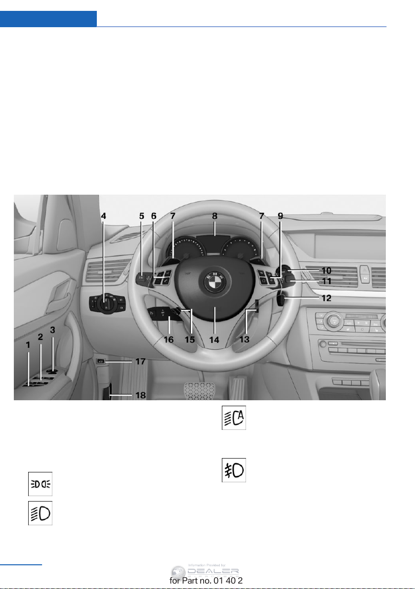
Vehicle equipment
This chapter describes all series equipment as
well as country-specific and special equipment
offered for this model series. Therefore, it also
describes equipment that may not be found in
your vehicle, for instance due to the selected
All around the steering wheel
special equipment or the country version. This
also applies to safety-related functions and
systems.
When using the features and systems descri‐
bed here, adhere to local regulations.
1 Safety switch for rear power win‐
dows 43
2 Power windows 42
3 Exterior mirror operation 51
4 Lamps
Parking lights 85
Low beams 85
14
Online Edition for Part no. 01 40 2 954 052 - II/15
Automatic headlight con‐
trol 86
Adaptive Light Control
High-beam Assistant 87
Front fog lamps 88
5 Steering column stalk, left
86
Page 17
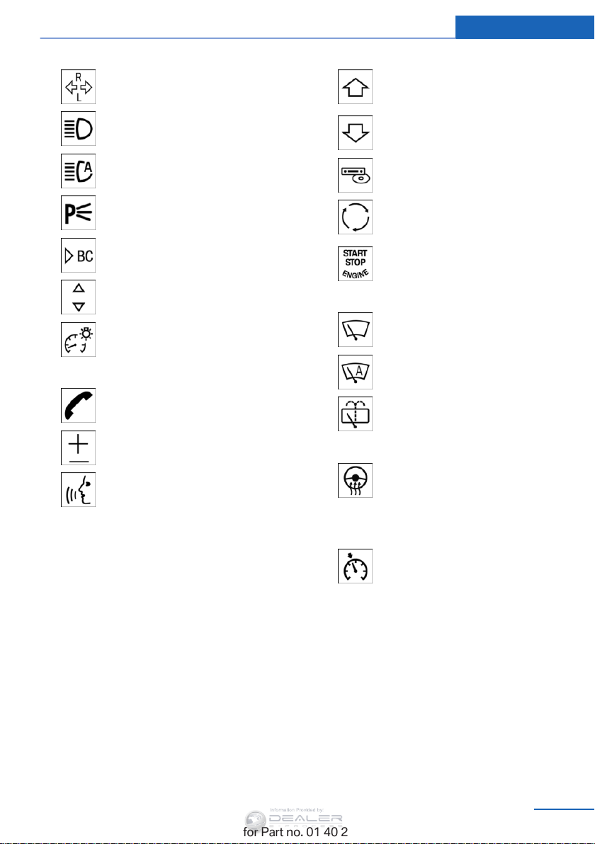
Cockpit At a glance
Information Provided by:
Turn signal 64
High-beams, head‐
light flasher 87
High-beam Assistant 87
Roadside parking lights 87
Computer 75
Settings and information about
the vehicle 76
Instrument lighting 89
6 Steering wheel buttons, left
Telephone 198
Volume
Activate/deactivate the voice acti‐
vation system 27
7 Shift paddles 69
8 Instrument cluster 16
9 Steering wheel buttons, right
Change the radio station
Select a music track
Scroll through the redial list
Next entertainment source
Recirculated air mode 112
10 Start/stop the engine and switch
the ignition on/off 59
11 Steering column stalk, right
Windshield wipers 64
Rain sensor 65
Rear window wiper 66
12 Ignition lock 59
13 Steering wheel heating 53
14 Horn, the entire surface
15 Adjust the steering wheel 53
16
Cruise control 103
17 Opening tailgate 38
18 Releasing the hood 243
Online Edition for Part no. 01 40 2 954 052 - II/15
15
Page 18
At a glance Cockpit
Information Provided by:
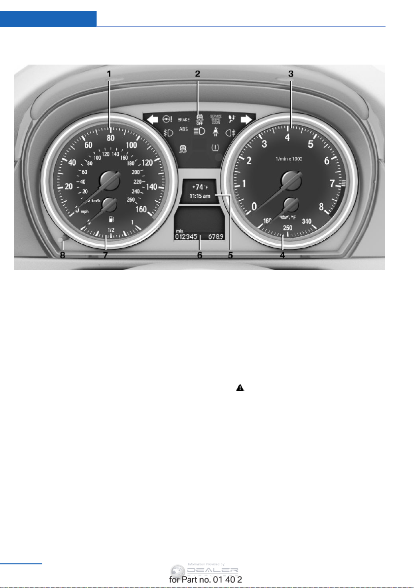
Instrument cluster
1 Speedometer
2 Indicator/warning lamps 17
3 Tachometer 74
4 Current fuel consumption 74
Engine oil temperature
74
5 Display for
▷ Clock 73
▷ External temperature 73
▷ Indicator/warning lamps 17
▷ Cruise control 103
6 Display for
▷ Automatic transmission position 68
16
Online Edition for Part no. 01 40 2 954 052 - II/15
▷ Hill Descent Control 101
▷ Computer 75
▷ Date of next scheduled service, and re‐
maining distance to be driven 80
▷ Odometer and trip odometer 73
▷ Resetting Tire Pressure Monitor 96
▷ Checking engine oil level 243
▷ Settings and information 76
Check Control message
▷
present 82
7 Fuel gauge 74
8 Resetting the trip odometer 73
Page 19
Cockpit At a glance
Information Provided by:
Indicator/warning lights
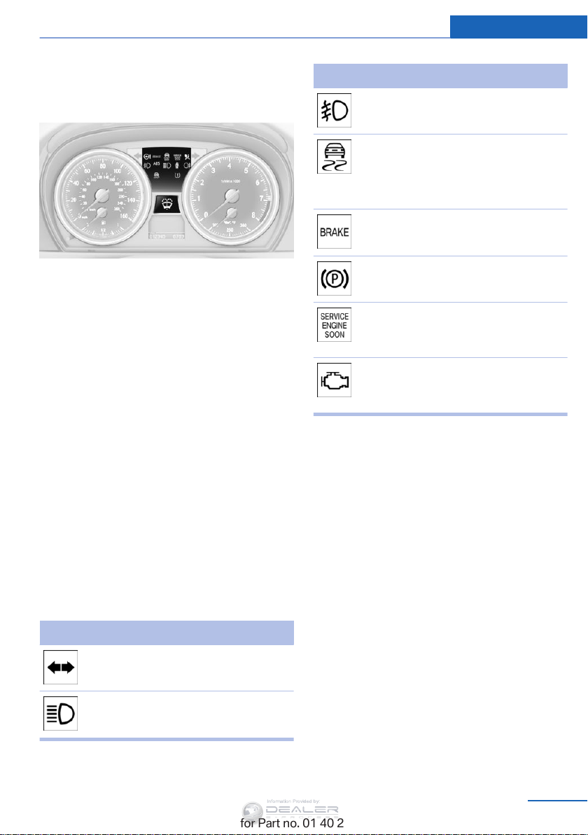
The concept
The indicator and warning lights can light up in
a variety of combinations and colors.
Several of the lights are checked for proper
functioning when the engine is started or the
ignition is switched on, and light up briefly.
Text messages
Text messages at the upper edge of the Con‐
trol Display explain the meaning of the dis‐
played indicator and warning lights.
Supplementary text messages
You can call up additional information, e.g., on
the cause of a malfunction and on how to re‐
spond, via Check Control, refer to page 82.
In urgent cases, this information will be shown
as soon as the corresponding light comes on.
Symbol Function or system
Front fog lamps, refer to page 88
Lamp flashes:
DSC or DTC is regulating the pro‐
pulsive forces in order to maintain
driving stability, refer to page 99
The parking brake is set, refer to
page 63
Canada: the parking brake is set, re‐
fer to page 63
Engine malfunction with adverse ef‐
fect on emissions, refer to
page 248
Canada: engine malfunction with
adverse effect on exhaust emis‐
sions, refer to page 248
Indicator lights without text messages
The following indicator lamps notify you that
certain functions are active:
Symbol Function or system
Turn signals, refer to page 64
High-beams/headlamp flasher, refer
to page 87
Online Edition for Part no. 01 40 2 954 052 - II/15
17
Page 20
At a glance Cockpit
Information Provided by:
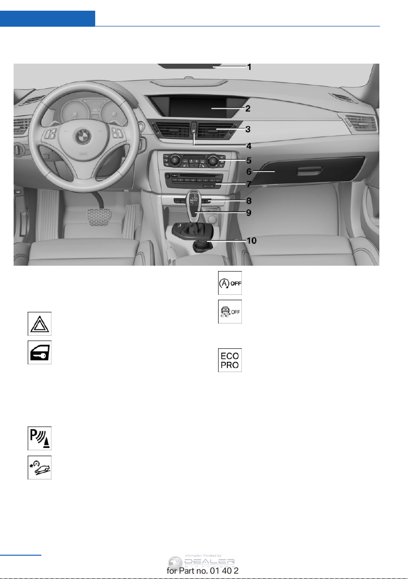
All around the center console
1 Headliner 19
2 Control Display 20
3 Air vent 113
4 Hazard warning system 257
Central locking system 37
5 Automatic climate control 110
6 Glove compartment 125
7 Radio and CD/DVD drive 168
Programmable memory buttons
8
PDC Park Distance Control 105
24
rearview camera 107
HDC Hill Descent Control 101
18
Online Edition for Part no. 01 40 2 954 052 - II/15
Deactivate the Automatic Engine
Start/Stop Function 61
DSC Dynamic Stability Con‐
trol 99
DTC Dynamic Traction Con‐
trol 100
ECO PRO 140
9 Selector lever with automatic transmis‐
sion 67
10 Controller with buttons 20
Page 21

All around the headliner
Information Provided by:
Cockpit At a glance
1 Emergency Request 257
2
Panoramic glass sunroof 44
3 Indicator lamp for the front pas‐
senger airbags 92
Online Edition for Part no. 01 40 2 954 052 - II/15
4 Reading lamps 89
5
Interior lamps 89
19
Page 22
At a glance iDrive
Information Provided by:
iDrive
Vehicle equipment
This chapter describes all series equipment as
well as country-specific and special equipment
offered for this model series. Therefore, it also
describes equipment that may not be found in
your vehicle, for instance due to the selected
special equipment or the country version. This
also applies to safety-related functions and
systems.
When using the features and systems descri‐
bed here, adhere to local regulations.
The concept
The iDrive combines the functions of a multi‐
tude of switches. Thus, these functions can be
operated from a central location.
Using the iDrive during a trip
To avoid becoming distracted and pos‐
ing an unnecessary hazard to your vehicle's
occupants and to other road users, never at‐
tempt to use the controls or enter information
unless traffic and road conditions allow this.
◀
The buttons can be used to open the me‐
nus directly. The controller can be used to
select menu items and create the settings.
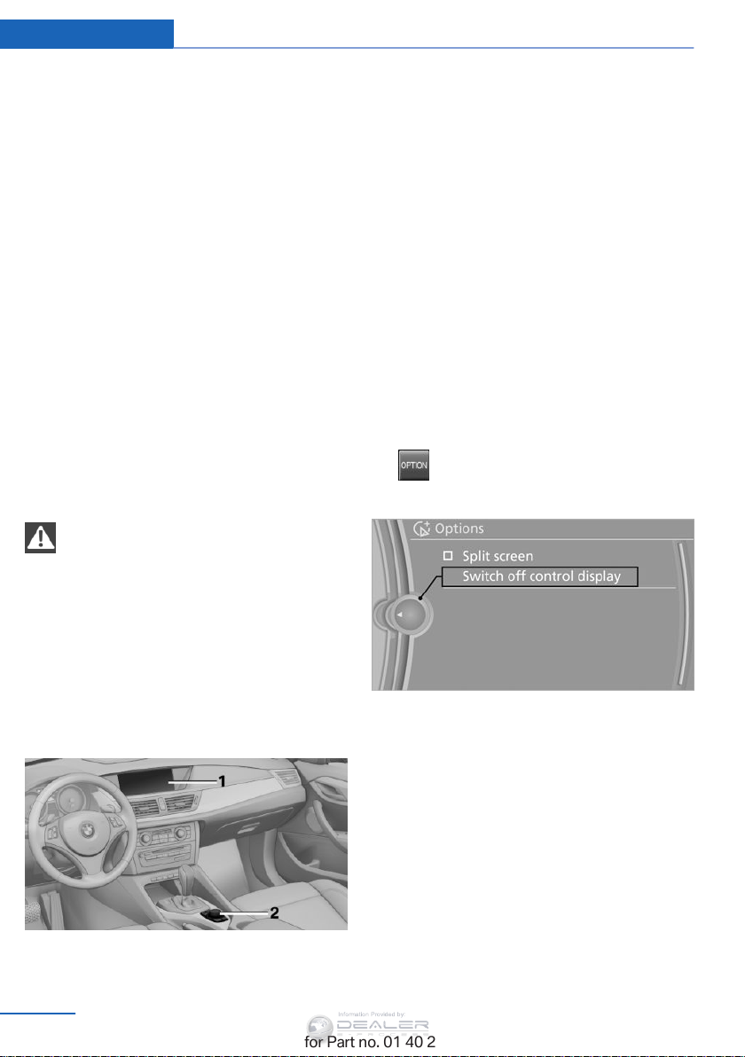
Control Display
Notes
▷ To clean the Control Display, follow the
care instructions, refer to page 266.
▷ Do not place objects close to the Control
Display; otherwise, the Control Display can
be damaged.
Switching off
1. Press the button.
2. "Switch off control display"
Controls at a glance
Controls
1 Control Display
2 Controller with buttons
20
Online Edition for Part no. 01 40 2 954 052 - II/15
Switching on
Press the controller again to switch the screen
back on.
Page 23
iDrive At a glance
Information Provided by:
Controller
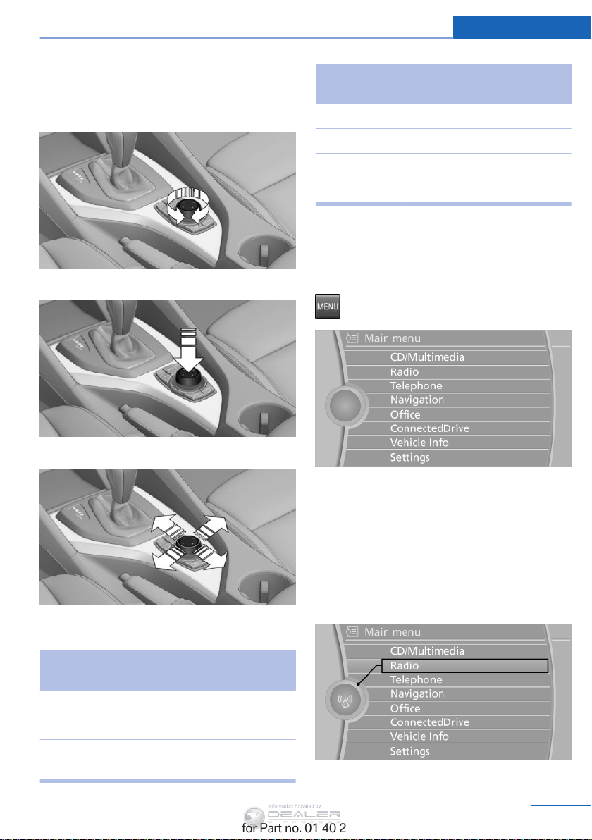
Select menu items and create settings.
1. Turn.
2. Press.
3. Move in four directions.
Press the but‐
ton
NAV Opens the Navigation menu.
TEL Opens the Telephone menu.
BACK Displays the previous panel.
OPTION Opens the Options menu.
Function
Operating concept
Opening the main menu
Press the button.
Buttons on controller
Press the but‐
ton
MENU Opens the main menu.
RADIO Opens the Radio menu.
MEDIA Opens the CD/Multimedia
Function
menu.
Online Edition for Part no. 01 40 2 954 052 - II/15
The main menu is displayed.
All iDrive functions can be called up via the
main menu.
Selecting menu items
Menu items shown in white can be selected.
1. Turn the controller until the desired menu
item is highlighted.
2. Press the controller.
21
Page 24
At a glance iDrive
Information Provided by:
Menu items in the Owner's Manual
In the Owner's Manual, menu items that can be
selected are set in quotation marks, e.g.,
"Settings".
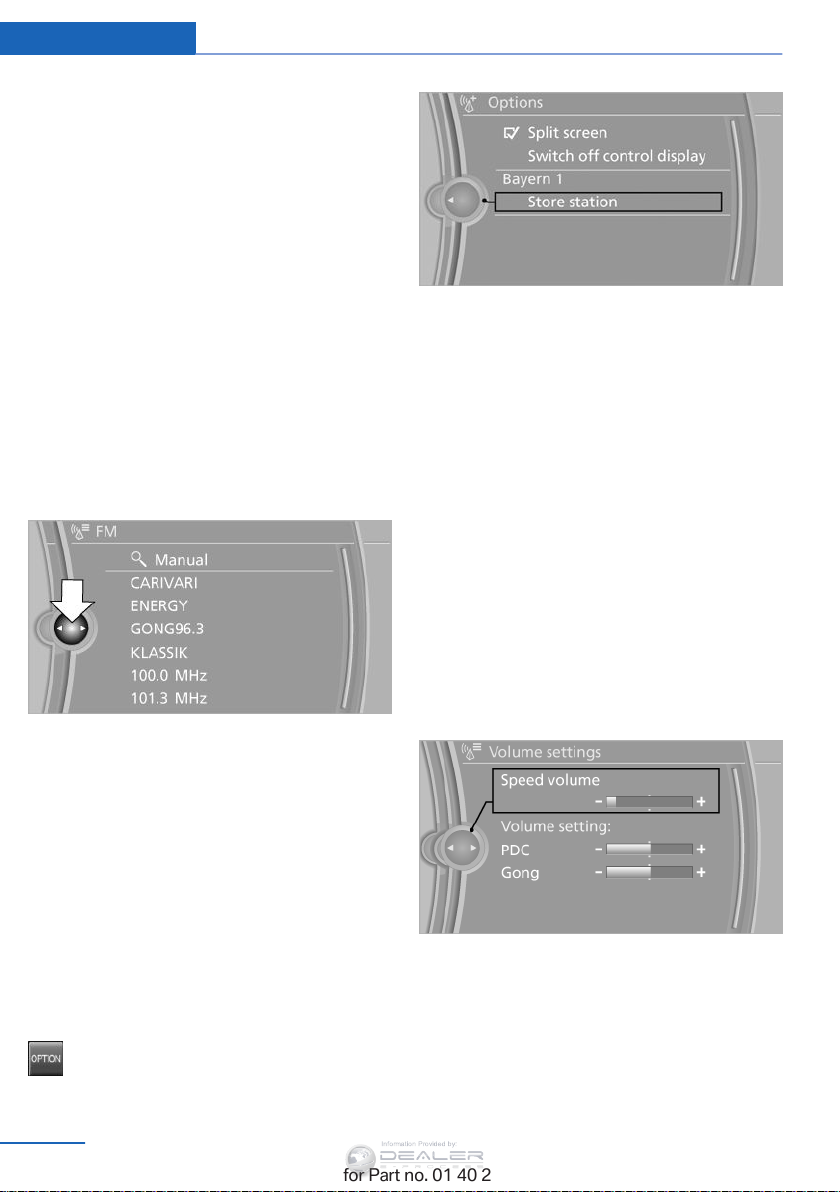
Changing between panels
After a menu item is selected, e.g.,
new panel is displayed. Panels can overlap.
▷ Move the controller to the left.
The current panel is closed and the previ‐
ous panel is displayed.
The previous panel is opened again by
pressing the BACK button. In this case, the
current panel is not closed.
▷ Move the controller to the right.
A new panel is opened on top of the previ‐
ous display.
"Radio", a
Additional options: move the controller to the
right repeatedly until the
displayed.
"Options" menu is
Options menu
The "Options" menu consists of various areas:
▷ Screen settings, e.g., "Switch off control
display"
▷ Control options for the selected main
menu, e.g., for "Radio".
▷ If applicable, further operating options for
the selected menu, for instance "Store
station".
.
White arrows pointing to the left or right indi‐
cate that additional panels can be opened.
View of an opened menu
When a menu is opened, it generally opens
with the panel that was last selected in that
menu. To display the first panel of a menu:
▷ Move the controller to the left repeatedly
until the first panel is displayed.
▷ Press the menu button on the controller
twice.
Opening the Options menu
Press the button.
The "Options" menu is displayed.
22
Online Edition for Part no. 01 40 2 954 052 - II/15
Changing settings
1. Select a field.
2. Turn the controller until the desired setting
is displayed.
3. Press the controller.
Activating/deactivating the functions
Several menu items are preceded by a check‐
box. It indicates whether the function is acti‐
vated or deactivated. Selecting the menu item
activates or deactivates the function.
Page 25
iDrive At a glance
Information Provided by:
Function is activated.
The function is deactivated.
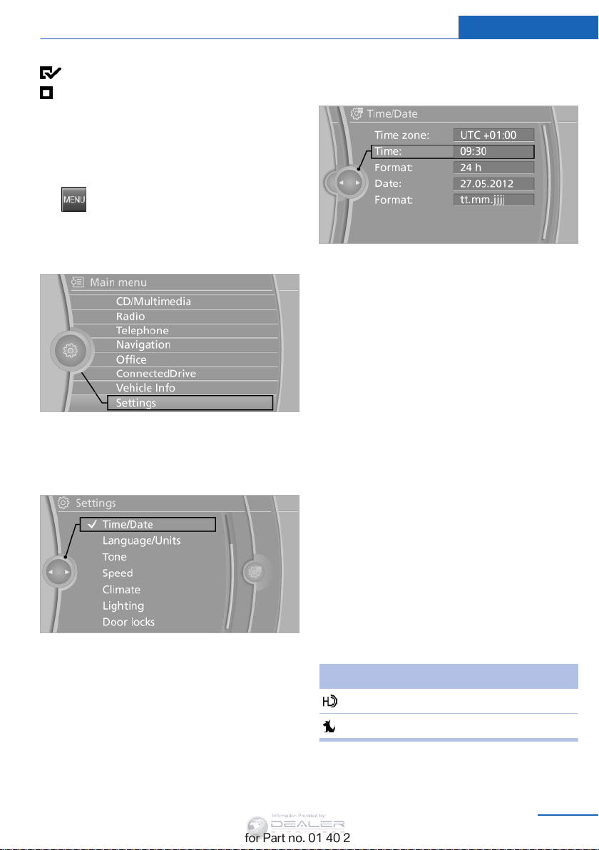
Example: setting the clock
Setting the clock
1. Press the button. The main menu is
displayed.
2. Turn the controller until "Settings" is high‐
lighted, and then press the controller.
3. If necessary, move the controller to the left
to display
4. Turn the controller until "Time/Date" is
highlighted, and then press the controller.
"Time/Date".
5. Turn the controller until "Time:" is high‐
lighted, and then press the controller.
6. Turn the controller to set the hours and
press the controller.
7. Turn the controller to set the minutes and
press the controller.
Status information
Status field
The following information is displayed in the
status field at the top right:
▷ Time.
▷ Current entertainment source.
▷ Sound output, on/off.
▷ Wireless network reception strength.
▷ Telephone status.
▷ Traffic bulletin reception.
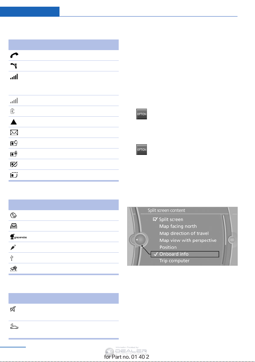
Status field symbols
The symbols are grouped into various catego‐
ries.
Radio symbols
Symbol Meaning
HD Radio™ is switched on.
Satellite radio is switched on.
Online Edition for Part no. 01 40 2 954 052 - II/15
23
Page 26
At a glance iDrive
Information Provided by:
Telephone symbols
Symbol Meaning
Incoming or outgoing call.
Missed call.
Wireless network reception
strength Symbol flashes: searching
for network.
Wireless network is not available.
Bluetooth is switched on.
Roaming is active.
Text message, e-mail was received.
Check the SIM card.
SIM card is blocked.
SIM card is missing.
Enter the PIN.
Entertainment symbols
Symbol Meaning
Split screen
General information
Additional information can be displayed on the
right side of the split screen, e.g., information
from the computer.
In the divided screen view, the so-called split
screen, this information remains visible even
when you change to another menu.
Switching the split screen on and off
1.
2. "Split screen"
Selecting the display
1. Press the button.
2. "Split screen"
3. Move the controller until the split screen is
4. Press the controller or select "Split screen
5. Select the desired menu item.
Press the button.
selected.
content".
CD/DVD player.
Music collection.
Gracenote® database.
AUX-IN port.
USB audio interface.
Music interface for smartphones.
Additional symbols
Symbol Meaning
Spoken instructions are switched
off.
Request of the current vehicle posi‐
tion.
24
Online Edition for Part no. 01 40 2 954 052 - II/15
Programmable memory buttons
General information
The iDrive functions can be stored on the pro‐
grammable memory buttons and called up di‐
rectly, e.g., radio stations, navigation destina‐
Page 27
iDrive At a glance
Information Provided by:
tions, phone numbers and entry points into the
menu.
The settings are stored for the remote control
currently in use.
Saving a function
1. Highlight the function via the iDrive.
2. Press the desired button for more
than two seconds.
Running a function
Press the button.
The function will run immediately. This
means, for example, that the number is dialed
when a phone number is selected.
Displaying the button assignment
Use a finger to touch the buttons. Do not wear
gloves or use objects.
The key assignment is displayed at the top
edge of the screen.
2. Select additional letters or numbers if
needed.
3. "OK": confirm the entry.
Symbol Function
Press the controller: delete the let‐
ter or number.
Press the controller for an extended
period: delete all letters or numbers.
Enter a blank space.
Switching between letters and
numbers
Depending on the menu, you can switch be‐
tween entering letters and numbers.
Symbol Function
Enter the letters.
Enter the numbers.
Switching between upper and lower
case letters
Depending on the menu, you can switch be‐
tween entering uppercase and lowercase let‐
ters.
Symbol Function
▷ To display short information: touch the
button.
▷ To display detailed information: touch the
button for an extended period.
Entering letters and numbers
1. Turn the controller: select letters or num‐
bers.
Online Edition for Part no. 01 40 2 954 052 - II/15
Move the controller forward:
switch from upper to lower case
letters.
Move the controller forward:
switch from lower to upper case
letters.
Entry comparison
Entry of names and addresses: the selection is
narrowed down every time a letter is entered
and letters may be added automatically.
The entries are continuously compared to the
data stored in the vehicle.
25
Page 28

At a glance iDrive
Information Provided by:
▷ Only those letters are offered during the
entry for which data is available.
▷ Destination search: town/city names can
be entered using the spelling of language
available on the Control Display.
26
Online Edition for Part no. 01 40 2 954 052 - II/15
Page 29

Voice activation system At a glance
Information Provided by:
Voice activation system
Vehicle equipment
This chapter describes all series equipment as
well as country-specific and special equipment
offered for this model series. Therefore, it also
describes equipment that may not be found in
your vehicle, for instance due to the selected
special equipment or the country version. This
also applies to safety-related functions and
systems.
When using the features and systems descri‐
bed here, adhere to local regulations.
The concept
▷ Most functions that are displayed on the
Control Display can be operated with the
voice activation system using spoken com‐
mands. The system prompts you to make
your entries.
▷ Functions that can only be used when the
vehicle is stationary cannot be operated
using the voice activation system.
▷ The system uses a special microphone lo‐
cated in the area of the interior rearview
mirror.
▷ ›...‹ Verbal instructions in the Owner's
Manual to use with the voice activation
system.
Requirements
Via the Control Display, set a language that is
also supported by the voice activation system
so that the spoken commands can be identi‐
fied.
Set the language, refer to page 79.
Using voice activation
Activating the voice activation system
1. Press the button on the steering
wheel.
2. Wait for the signal.
3. Say the command.
The command appears on the Control Dis‐
play.
The symbol on the Control Display indi‐
cates that the voice activation system is active.
If no other commands are available, operate
the function via iDrive in this case.
Terminating the voice activation
system
Briefly press the button on the steer‐
ing wheel or ›Cancel‹.
Possible commands
Most menu items on the Control Display can
be voiced as commands.
The available commands depend on the menu
that is currently displayed on the Control Dis‐
play.
The functions of the main menu have short
commands.
Some list items, such as the phone book en‐
tries, can also be selected via the voice activa‐
tion system. Say the list items exactly as they
are displayed on the list.
Having possible commands read aloud
You can have the system read possible com‐
mands aloud: ›
Voice commands‹.
Online Edition for Part no. 01 40 2 954 052 - II/15
27
Page 30
At a glance Voice activation system
Information Provided by:
For example, if the "Settings" menu is dis‐
played, the commands for the settings are
read out loud.
Executing functions using short
commands
Functions on the main menu can be performed
directly by means of short commands, usually
irrespective of which menu item is currently
selected, for instance ›
List of short commands of the voice activation
system, refer to page 272.
Vehicle status‹.
Help dialog for the voice activation
system
Calling up help dialog: ›Help‹
Additional commands for the help dialog:
▷ ›Help with examples‹: information about the
current operating options and the most im‐
portant commands for them are an‐
nounced.
▷ ›Help with voice activation‹: information
about the principle of operation for the
voice activation system is announced.
Example: playing back a CD
Via the main menu
The commands of the menu items are spoken
out loud, in the same way as they are selected
via the controller.
1. Switch on the Entertainment sound output
if necessary.
6. Press the button on the steering
wheel again to select a specific track.
7. ›Track ...‹ e.g., CD track 4.
Via short commands
Playback of the CD can also be started using a
short command.
1. Switch on the Entertainment sound output
if necessary.
2. Press the button on the steering
wheel.
3. ›C D drive Track ...‹ e.g., CD track 4.
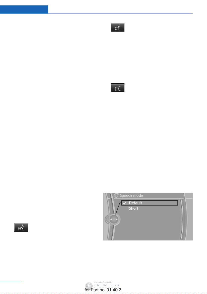
Setting the voice dialog
You can set whether the system should use
the standard dialog or a shorter version.
In the shorter variant of the voice dialog, the
announcements from the system are issued in
an abbreviated form.
On the Control Display:
1. "Settings"
2. "Language/Units"
3. "Speech mode:"
4. Select the setting.
2.
3. ›C D and multimedia‹
4. ›C D‹
5. ›C D drive‹
Press the button on the steering
wheel.
The medium last played is played back.
The CD is played back.
28
Online Edition for Part no. 01 40 2 954 052 - II/15
Adjusting the volume
Turn the volume button during the spoken in‐
structions until the desired volume is set.
Page 31

▷ The volume remains constant even if the
Information Provided by:
volume of other audio sources is changed.
▷ The volume is stored for the remote con‐
trol currently in use.
Notes on Emergency Requests
Do not use the voice activation system to ini‐
tiate an Emergency Request. In stressful situa‐
tions, the voice and vocal pitch can change.
This can unnecessarily delay the establish‐
ment of a telephone connection.
Instead, use the SOS button, refer to
page 257, in the vicinity of the interior mirror.
Environmental conditions
▷ Say the commands, numbers, and letters
smoothly and with normal volume, empha‐
sis, and speed.
▷ Always say commands in the language of
the voice activation system.
▷ Keep the doors, windows, and glass sun‐
roof closed to prevent noise interference.
▷ Avoid making other noise in the vehicle
while speaking.
Voice activation system At a glance
Online Edition for Part no. 01 40 2 954 052 - II/15
29
Page 32
Information Provided by:
Online Edition for Part no. 01 40 2 954 052 - II/15
Page 33
Controls
Information Provided by:
This chapter is intended to provide you with
information that will give you complete control of
your vehicle. All features and accessories that
are useful for driving and your safety, comfort
and convenience are described here.
Online Edition for Part no. 01 40 2 954 052 - II/15
Page 34
Controls Opening and closing
Information Provided by:
Opening and closing
Vehicle equipment
This chapter describes all series equipment as
well as country-specific and special equipment
offered for this model series. Therefore, it also
describes equipment that may not be found in
your vehicle, for instance due to the selected
special equipment or the country version. This
also applies to safety-related functions and
systems.
When using the features and systems descri‐
bed here, adhere to local regulations.
Remote control/key
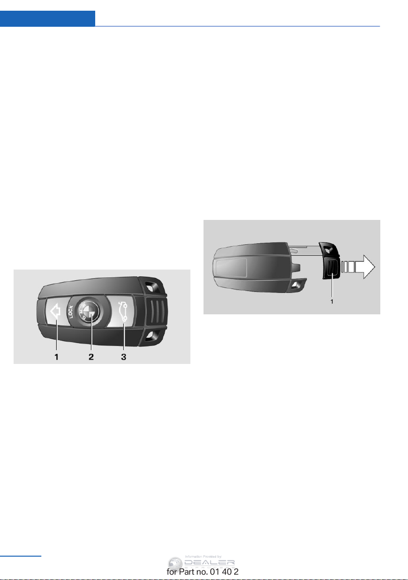
Buttons on the remote control
In vehicles equipped with Comfort Access, the
remote control contains a replaceable battery,
refer to page 41.
The settings called up and implemented when
the vehicle is unlocked depend on which re‐
mote control is used to unlock the vehicle, re‐
fer to Personal Profile.
In addition, information about service require‐
ments is stored in the remote control, Service
data in the remote control, refer to page 247.
Integrated key
Press button 1 and pull out the key.
The integrated key fits the following locks:
▷ Driver's door, refer to page 36.
1 Unlocking
2 Locking
3 Opening tailgate
General information
The vehicle is supplied with two remote con‐
trols with keys.
Each remote control contains a rechargeable
battery that is automatically recharged when it
is in the ignition lock while the car is being
driven. Use each remote control at least twice
a year for longer road trips in order to maintain
the batteries' charge status.
32
Online Edition for Part no. 01 40 2 954 052 - II/15
New remote controls
You can obtain new remote controls from your
service center.
Loss of the remote controls
Lost remote controls can be blocked by your
service center.
Personal Profile
The concept
You can set several of your vehicle's functions
to suit your personal needs and preferences.
Page 35

Opening and closing Controls
Information Provided by:
▷ The settings are automatically saved in the
profile currently activated in the remote
control.
▷ The remote control used is detected when
the vehicle is unlocked and the stored pro‐
file is called up.
▷ Your personal settings will be recognized
and called up again even if the vehicle has
been used in the meantime by someone
else with another remote control.
The individual settings are stored for a maxi‐
mum of four remote controls. They are stored
for two remote controls if Comfort Access is in
use.
Personal Profile settings
The following functions and settings can be
stored in a profile.
More information on the settings can be found
under:
▷ Assigning the programmable memory but‐
tons, refer to page 24.
▷ Response of the central locking system
when the car is being unlocked, refer to
page 34.
▷ Automatic locking of the vehicle, refer to
page 37.
▷ Automatic call-up of the driver's seat posi‐
tion after unlocking, refer to page 35.
▷ Settings for the display on the Control Dis‐
play and in the instrument cluster:
▷ 12h/24h clock format, refer to
page 78.
▷ Date format, refer to page 79.
▷ Brightness of the Control Display, refer
to page 80.
▷ Language on the Control Display, refer
to page 79.
▷ Units of measure for fuel consumption,
distance covered/remaining distances,
and temperature, refer to page 77.
▷ Show visual warning for the Park Distance
Control PDC, refer to page 106.
▷ rearview camera:
▷ Function selection, refer to page 107.
▷ Type of display, refer to page 109.
▷ Light settings:
▷ Triple turn signal activation, refer to
page 64.
▷ Welcome lights, refer to page 85.
▷ Headlight courtesy delay feature, refer
to page 86.
▷ Daytime running lights, refer to
page 86.
▷ High-beam Assistant, refer to
page 87.
▷ Automatic climate control: AUTO program,
cooling function and automatic recircu‐
lated air control activated/deactivated,
temperature, air flow rate and distribution,
refer to page 110.
▷ Navigation:
▷ Voice activation, refer to page 157.
▷ Route criteria, refer to page 155.
▷ Map view settings, refer to page 159.
▷ Entertainment:
▷ Tone control, refer to page 166.
▷ Radio, stored stations, refer to
page 174.
▷ CD/multimedia, audio source listened
to last, refer to page 176.
▷ Telephone: volume, refer to page 202.
Central locking system
The concept
The central locking system becomes active
when the driver's door is closed.
The system simultaneously engages and re‐
leases the locks on the following:
Online Edition for Part no. 01 40 2 954 052 - II/15
33
Page 36

Controls Opening and closing
Information Provided by:
▷ Doors.
▷ Tailgate.
▷ Fuel filler flap.
Operating from the outside
▷ Via the remote control.
▷ In cars with Comfort Access, via the door
handles on the driver's and front passen‐
ger sides.
The following takes place simultaneously
when locking/unlocking the vehicle via the re‐
mote control:
▷ The welcome lamps, interior lamps and
courtesy lamps are switched on and off.
▷ The alarm system is armed or disarmed,
refer to page 41.
Operating from the inside
Via the button for the central locking system,
refer to page 37.
If the vehicle is locked from the inside, the fuel
filler flap remains unlocked.
If an accident of a certain severity occurs, the
central locking system unlocks automatically.
The hazard warning system and interior lamps
come on.
Unlocking
Press the button. The vehicle is unlocked.
The welcome lamps, interior lamps, and cour‐
tesy lamps are switched on.
You can set how the vehicle is to be unlocked.
The setting is stored for the remote control
currently in use.
1. "Settings"
2. "Door locks"
3. "Unlock button:"
4. Select the desired function:
▷ "All doors"
The entire vehicle is unlocked.
▷ "Driver's door only"
Only the driver's door and the fuel
filler flap are unlocked. Pressing again
unlocks the entire vehicle.
Opening and closing: from the outside
Using the remote control
General information
Take the remote control with you
People or animals left unattended in a
parked vehicle can lock the doors from the in‐
side. Always take the remote control with you
when leaving the vehicle so that the vehicle
can then be opened from the outside.
34
Online Edition for Part no. 01 40 2 954 052 - II/15
◀
Convenient opening
Press and hold the button on the remote
control.
The windows and the panoramic glass sunroof
open.
Locking
Press the button on the remote con‐
trol.
Page 37
Opening and closing Controls
Information Provided by:
Locking from the outside
Do not lock the vehicle from the outside
if there are people in it, as the vehicle cannot
be unlocked from inside without special knowl‐
edge.◀
Switching on the interior lamps and
courtesy lamps
Press the button on the remote con‐
trol with the vehicle locked.
Panic mode
You can trigger the alarm system if you find
yourself in a dangerous situation.
Press the button on the remote control for
at least 3 seconds.
To switch off the alarm: press any button.
Unlocking tailgate
Press the button on the remote control for
approx. 1 second and release.
The tailgate will open slightly, regardless of
whether it was previously locked or unlocked.
The tailgate pivots back and up when it opens.
Ensure that adequate clearance is available
before opening.
To avoid locking yourself out of the vehicle, do
not place the remote control into the cargo
area. The tailgate is locked again as soon as it
is pushed closed.
Before and after each trip, check that the tail‐
gate has not been inadvertently unlocked.
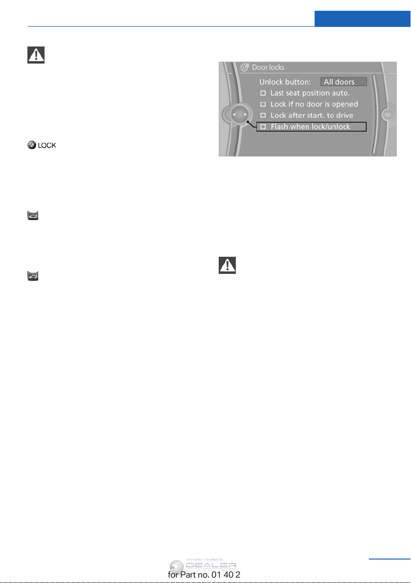
Confirmation signals from the vehicle
1. "Settings"
2. "Door locks"
3. "Flash when lock/unlock"
Retrieving the seat and mirror settings
The driver's seat and exterior mirror positions
used last are stored for the remote control cur‐
rently in use.
When the vehicle is being unlocked, these po‐
sitions are automatically retrieved if the setting
is activated.
Pinch hazard when moving back the seat
If this function is used, first make sure
that the footwell behind the driver's seat is
empty. Failure to do so could cause injury to
persons or damage to objects behind the seat
as a result of a rearward movement of the
seat.◀
The adjustment procedure is interrupted:
▷ When a seat position switch is pressed.
▷ When a button of the seat and mirror mem‐
ory is pressed.
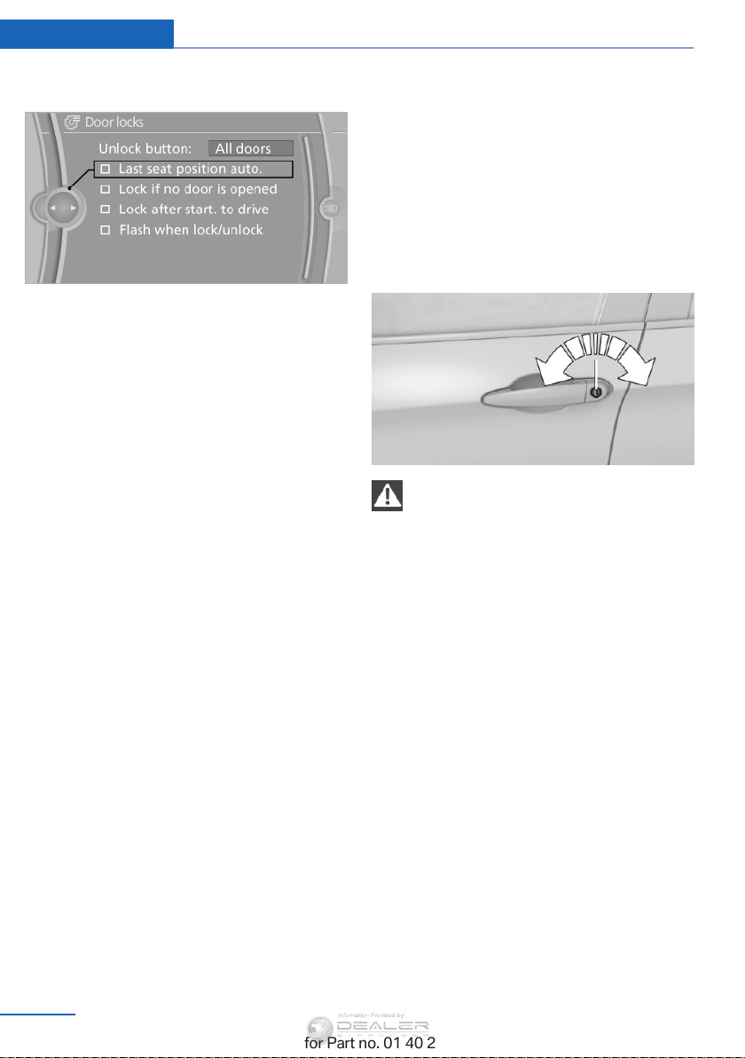
Selecting automatic activation
1. "Settings"
2. "Door locks"
Online Edition for Part no. 01 40 2 954 052 - II/15
35
Page 38
Controls Opening and closing
Information Provided by:
3. "Last seat position auto."
Malfunctions
Local radio waves may interfere with the re‐
mote control.
In this case, unlock and lock the car at the door
lock with the integrated key.
If the car can no longer be locked with a re‐
mote control, the battery in the remote control
is discharged. Use the remote control during
an extended drive in order to recharge the bat‐
tery, refer to page 32.
The remote control for Comfort Access con‐
tains a battery that may need to be replaced,
refer to page 41.
For US owners only
The transmitter and receiver units comply with
part 15 of the FCC/Federal Communication
Commission regulations. Operation is gov‐
erned by the following:
FCC ID:
LX8766S
LX8766E
LX8CAS
Compliance statement:
This device complies with part 15 of the FCC
Rules. Operation is subject to the following
two conditions:
▷ This device may not cause harmful inter‐
ference, and
▷ this device must accept any interference
received, including interference that may
cause undesired operation.
Any unauthorized modifications or changes to
these devices could void the user's authority to
operate this equipment.
Using the door lock
General information
Locking from the outside
Do not lock the vehicle from the outside
if there are people in it, as the vehicle cannot
be unlocked from inside without special knowl‐
edge.◀
The alarm system, refer to page 41, is not
deployed when the vehicle is locked with the
integrated key. The alarm system is triggered
when the door is opened if the vehicle was un‐
locked via the door lock.
To stop the alarm, unlock the vehicle with the
remote control or insert the remote control into
the ignition lock all the way.
Only the driver's door can be locked via the
door lock.
Locking the doors, the fuel filler flap,
and the tailgate all at once
To lock all doors, the fuel filler flap, and the tail‐
gate at once:
1. With the doors closed, lock the vehicle us‐
ing the button for the central locking sys‐
tem in the interior, refer to page 37.
36
Online Edition for Part no. 01 40 2 954 052 - II/15
Page 39
Opening and closing Controls
Information Provided by:
2. Unlock and open the driver's or front pas‐
senger door, refer to page 37.
3. Lock the vehicle as follows:
▷ Press down the lock button of the front
passenger door and close the door
from the outside.
▷ Lock the driver's door using the
integrated key in the door lock.
Manual operation
If an electrical malfunction occurs, unlock or
lock the driver's door using the integrated key
in the door lock. The other doors must be un‐
locked or locked from the inside.
Opening and closing: from the inside
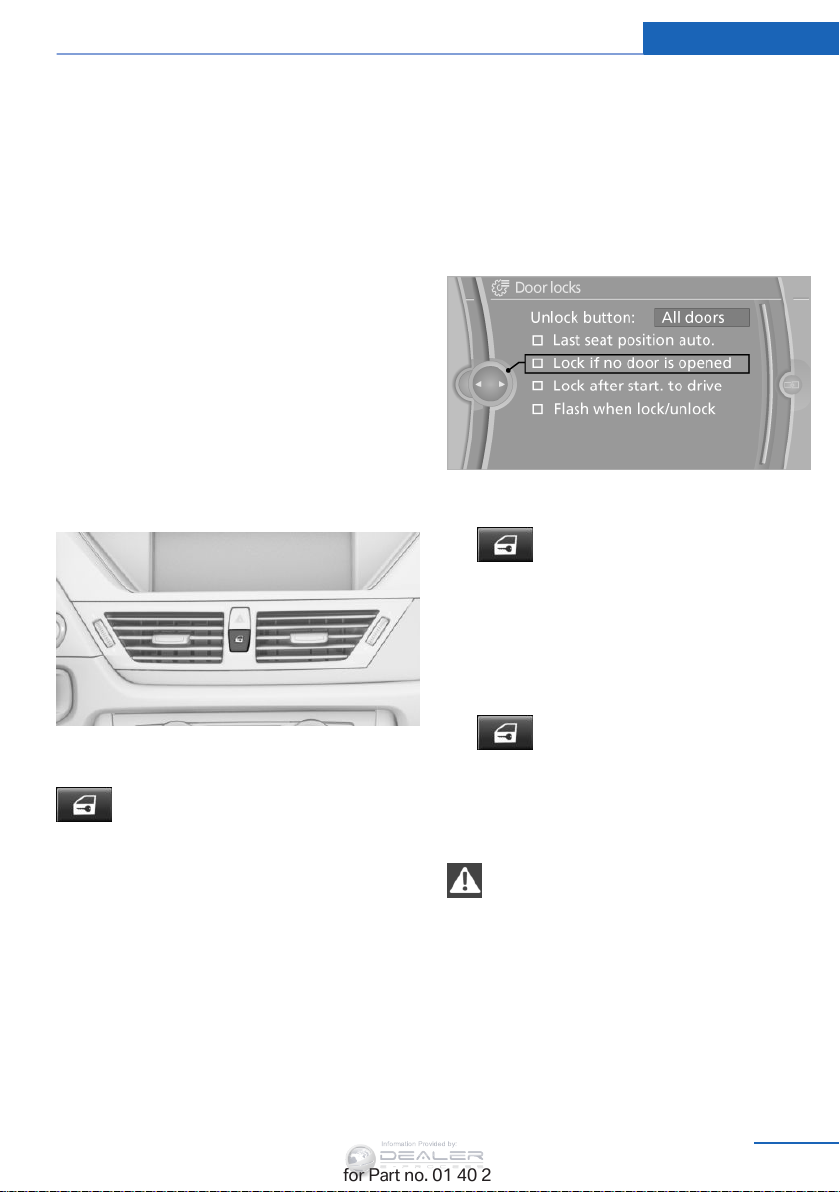
▷ "Lock if no door is opened"
The vehicle locks automatically after a
short period of time if a door is not
opened.
▷ "Lock after start. to drive"
The vehicle locks automatically after
you drive away.
Unlocking and opening
▷ Press the button. The doors are
unlocked. To open, pull the door
handle above the armrest.
▷ Pull the door handle above the armrest
twice: the door is unlocked the first time
and opened the second time.
Locking and unlocking
Press the button in the vehicle.
The doors and the tailgate are locked or un‐
locked when the front doors are closed, but
they are not secured against theft.
The fuel filler flap remains unlocked.
Automatic locking
The setting is stored for the remote control
currently in use.
1. "Settings"
2. "Door locks"
3. Select the desired function:
Online Edition for Part no. 01 40 2 954 052 - II/15
Locking
▷ Press the button. The doors are
locked.
▷ Press the lock button of a door. To prevent
you from being locked out, the opened
driver's door cannot be locked using the
lock button.
Take the remote control with you
People or animals left unattended in a
parked vehicle can lock the doors from the in‐
side. Always take the remote control with you
when leaving the vehicle so that the vehicle
can then be opened from the outside.
◀
37
Page 40
Controls Opening and closing
Information Provided by:
Tailgate
Opening
The tailgate pivots back and up when it opens.
Ensure that adequate clearance is available
before opening.
Provide edge protection
Sharp or angular objects can hit the rear
window while driving and damage the heating
wires of the rear window. Provide edge protec‐
tion.◀
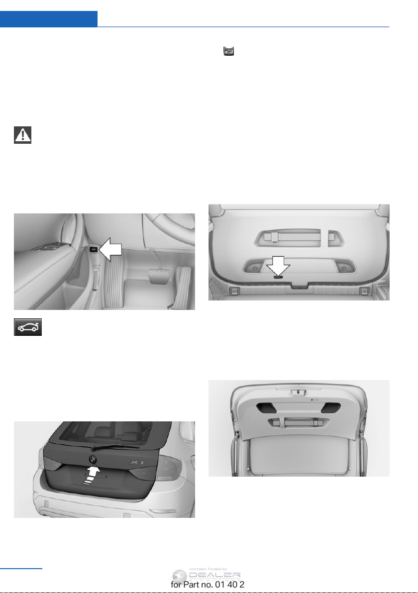
Opening from the inside
Press the button.
The tailgate is opened if the vehicle is
stationary, provided that the tailgate has not
been locked.
In some market-specific versions, this button
does not exist.
▷ Press the remote control button for ap‐
prox. 1 second and then release.
The tailgate opens slightly. It can be swung
upward.
Opening manually
In case of an electrical malfunction:
1. Fold down the rear seat backrest, enlarge
the cargo area, refer to page 121.
2. From the cargo area, press out the handle
in the tailgate, see arrow, and pull out as far
as possible. The tailgate is unlocked.
3. Open the tailgate from the outside and
press in the handle.
The tailgate is locked again as soon as it is
closed.
Closing
Opening from the outside
▷ Press the button next to the tailgate.
38
Online Edition for Part no. 01 40 2 954 052 - II/15
Recessed grips on the inside trim of the tail‐
gate can be used to conveniently pull down the
tailgate.
Before closing the tailgate, ensure that the
cargo area floor panel is not raised, refer to
page 123.
Page 41
Opening and closing Controls
Information Provided by:
Keep the closing area clear
Make sure that the closing area of the
tailgate is clear; otherwise, injuries or damage
may result.◀
Comfort Access
The concept
The vehicle can be accessed without activat‐
ing the remote control.
All you need to do is to have the remote con‐
trol with you, e.g., in your jacket pocket.
The vehicle automatically detects the remote
control when it is nearby or in the passenger
compartment.
Comfort Access supports the following func‐
tions:
▷ Unlocking/locking of the vehicle.
▷ Unlocking of the tailgate separately.
▷ Starting the engine.
▷ Convenient closing.
Functional requirement
▷ To lock the vehicle, the remote control
must be located outside of the vehicle.
▷ The next unlocking and locking cycle is not
possible until after approx. 2 seconds.
▷ The engine can only be started if the re‐
mote control is inside the vehicle.
Comparison with ordinary remote
control
The functions can be controlled by pressing
the buttons or via Comfort Access.
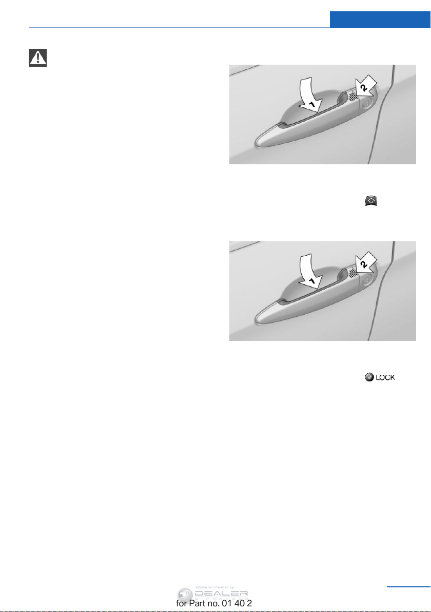
Unlocking
Grasp the handle on the driver's or front pas‐
senger door completely, arrow 1.
This corresponds to pressing the button.
Locking
Touch the area on the door handle, arrow 2,
with your finger for approx. 1 second.
This corresponds to pressing the but‐
ton.
To save battery power, ensure that the ignition
and all electronic systems and/or power con‐
sumers are switched off before locking the ve‐
hicle.
If a remote control is detected within the vehi‐
cle, the vehicle does not lock or is unlocked
again.
Convenient closing
Press the area, arrow 2, with your finger and
hold.
In addition, the windows and the panoramic
glass sunroof close.
Online Edition for Part no. 01 40 2 954 052 - II/15
39
Page 42
Controls Opening and closing
Information Provided by:
Monitor the closing process
Watch during the closing process to be
sure that no one is injured. Removing the hand
from the door handle immediately stops the
closing process.◀
Unlocking the tailgate separately
Press the button on the exterior of the tailgate.
This corresponds to pressing the button.
If a remote control accidentally left in the cargo
area is detected in the locked vehicle, the tail‐
gate opens again.
Ignition on
Pressing the Start/Stop button switches the
ignition on.
When doing so, do not depress the brake
pedal, otherwise the engine will start.
Starting the engine
The engine can be started or the ignition can
be switched on when a remote control is inside
the vehicle. It is not necessary to insert a re‐
mote control into the ignition lock, refer to
page 59.
If this occurs, open or close the vehicle using
the buttons on the remote control or use the
integrated key in the door lock.
Mechanical activation using the integrated key
only locks/unlocks the driver's door.
To start the engine afterward, insert the re‐
mote control into the ignition switch.
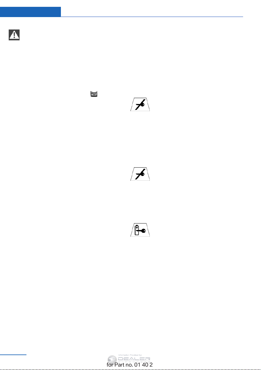
Warning lights
The warning light in the instrument
cluster lights up when you attempt to
start the engine: the engine cannot
be started.
The remote control is not in the vehicle or has
a malfunction. Take the remote control with
you inside the vehicle or have it checked. If
necessary, insert another remote control into
the ignition switch.
The warning lamp in the instrument
cluster lights up while the engine is
running: the remote control is no lon‐
ger inside the vehicle.
After switching off the engine, the engine can
only be started again within approx. 10 sec‐
onds if no door has been opened.
Switching off the engine in cars with
automatic transmission
The engine can only be switched off with
transmission position P engaged, refer to
page 61.
To switch the engine off with transmission po‐
sition N engaged, insert the remote control in
the ignition lock.
Malfunction
The Comfort Access functions can be distur‐
bed by local radio waves, such as by a mobile
phone in the immediate vicinity of the remote
control or when a mobile phone is being
charged in the vehicle.
40
Online Edition for Part no. 01 40 2 954 052 - II/15
The indicator lamp in the instrument
cluster comes on and a message ap‐
pears on the Control Display: replace
the remote control battery.
Page 43
Opening and closing Controls
Information Provided by:
Replacing the battery
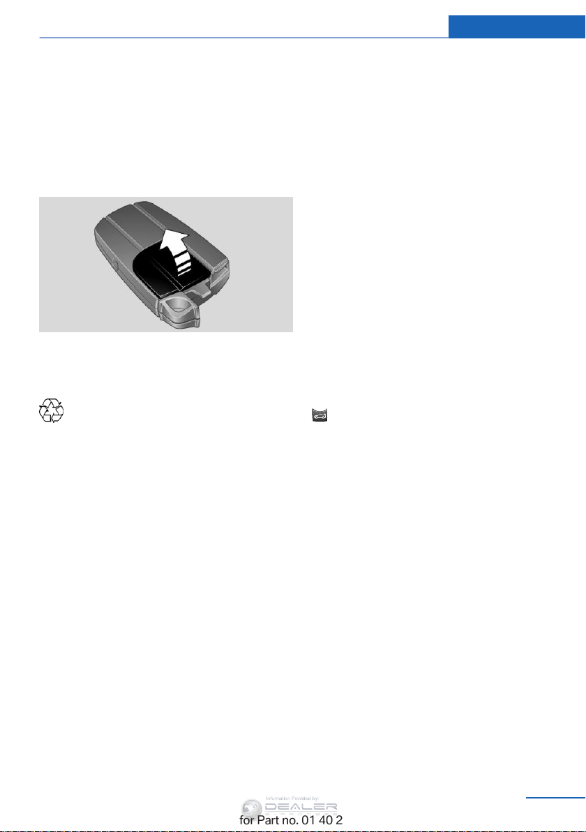
The remote control for Comfort Access con‐
tains a battery that will need to be replaced
from time to time.
1. Take the integrated key out of the remote
control, refer to page 32.
2. Remove the cover.
3. Insert a new battery of the same type with
the positive side facing upwards.
4. Press on the cover to close it.
Return used battery to a recycling center
or to your service center.
Alarm system
The concept
The vehicle alarm system responds to:
▷ Opening of a door, the hood or the tailgate.
▷ Movements in the vehicle: interior motion
sensor, refer to page 42.
▷ Changes in the vehicle tilt, e.g., during at‐
tempts to steal a wheel or tow the car.
▷ Interruptions in battery voltage.
The alarm system briefly indicates tampering:
▷ By sounding an acoustic alarm.
▷ By switching on the hazard warning sys‐
tem.
▷ By flashing the high beams.
Arming and disarming the alarm
system
General information
When you lock or unlock the vehicle, either
with the remote control or via Comfort Access,
the alarm system is armed or disarmed at the
same time.
Door lock and armed alarm system
The alarm system is triggered when the door is
opened if the vehicle was unlocked via the
door lock.
To stop this alarm, unlock the vehicle with the
remote control or insert the remote control into
the ignition lock all the way and switch on the
ignition.
Tailgate and armed alarm system
The tailgate can be opened using the remote
control, even if the alarm system is armed.
Press the button on the remote control.
After the tailgate is closed, it is locked and
monitored again by the alarm system. The haz‐
ard warning system flashes once.
In some market-specific versions, the tailgate
can only be opened using the remote control if
the vehicle was unlocked first.
Switching off the alarm
▷ Unlock the vehicle using the remote con‐
trol, refer to page 34.
▷ Insert the remote control all the way into
the ignition lock.
Online Edition for Part no. 01 40 2 954 052 - II/15
41
Page 44
Controls Opening and closing
Information Provided by:
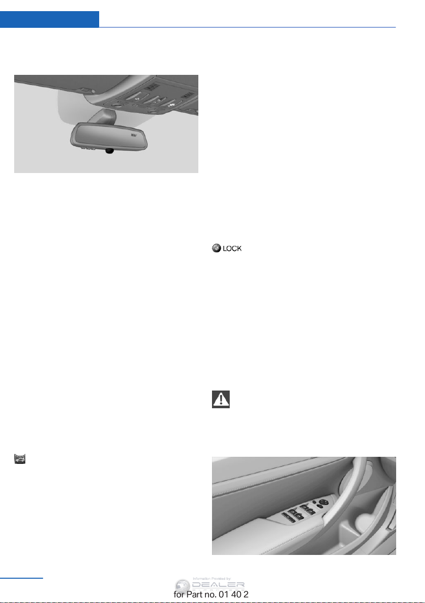
Indicator lamp on the interior rearview
mirror
▷ The indicator lamp flashes briefly every
2 seconds:
The system is armed.
▷ The indicator lamp flashes after locking:
The doors, hood or tailgate is not closed
properly, but the rest of the vehicle is se‐
cured.
The indicator lamp flashes continuously af‐
ter approx. 10 seconds. The interior motion
sensor is not active.
▷ The indicator lamp goes out after unlock‐
ing:
The vehicle has not been tampered with.
▷ If the indicator lamp flashes after unlocking
until the remote control is inserted in the
ignition, but for no longer than approx.
5 minutes:
An alarm has been triggered.
Panic mode
In dangerous situations, trigger the alarm sys‐
tem:
Press the button on the remote control for
at least 3 seconds.
To switch off the alarm: press any button.
Interior motion sensor
For the sensor to function properly, the win‐
dows and panoramic glass sunroof must be
closed.
Avoiding unintentional alarms
The tilt alarm sensor and interior motion sen‐
sor can be switched off together, such as in
the following situations:
▷ In duplex garages.
▷ During transport on car-carrying trains, at
sea or on a trailer.
▷ When animals are to remain in the vehicle.
Switching off the tilt alarm sensor and
interior motion sensor
Press the remote control button again
within 10 seconds after the vehicle is locked.
The indicator lamp lights up for approx. 2 sec‐
onds and then flashes continuously.
The tilt alarm sensor and interior motion sen‐
sor remain switched off until the vehicle is
locked again.
Power windows
General information
Take the remote control with you
Take the remote control with you when
leaving the vehicle so that children, for exam‐
ple, cannot operate the power windows and in‐
jure themselves.◀
Tilt alarm sensor
The tilt of the vehicle is monitored.
The alarm system responds in situations such
as attempts to steal a wheel or tow the car.
42
Online Edition for Part no. 01 40 2 954 052 - II/15
Page 45
Opening and closing Controls
Information Provided by:
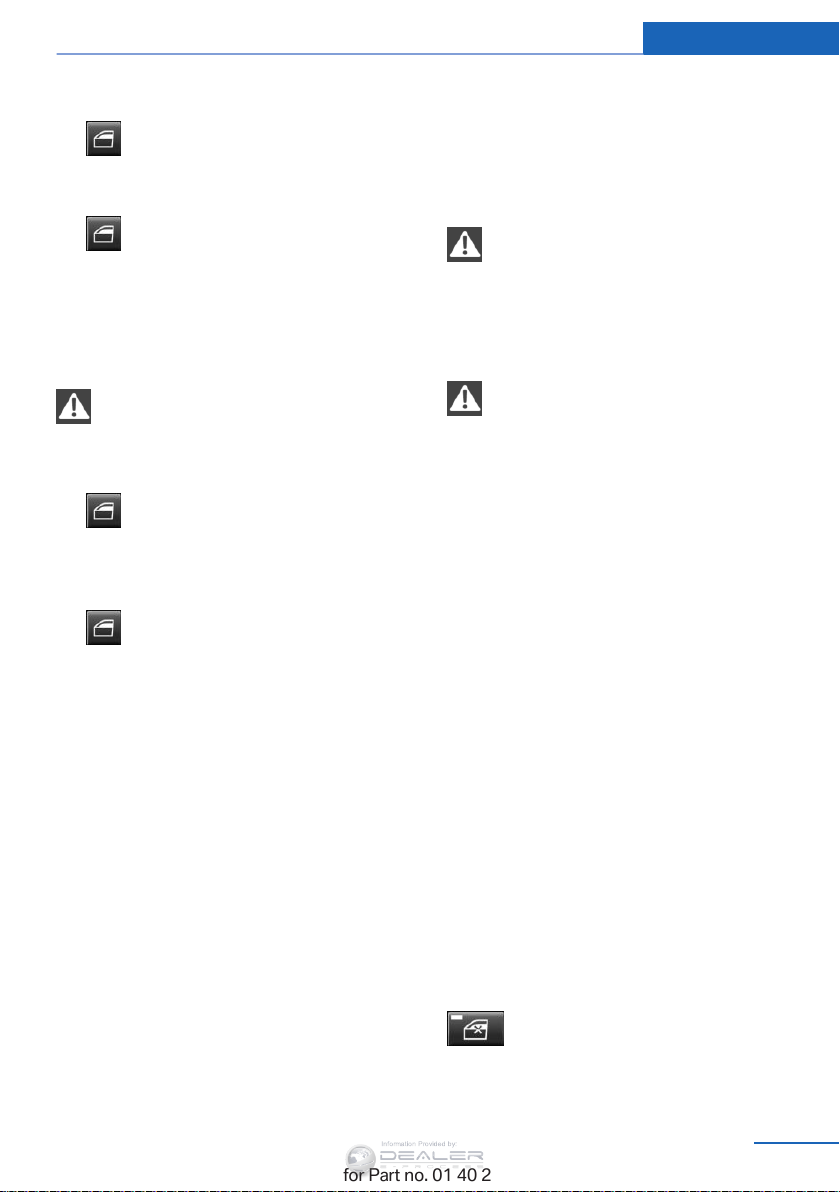
Opening
▷ Press the switch to the resistance
point.
The window opens while the switch is held.
▷ Press the switch beyond the resist‐
ance point.
The window opens automatically.
Pressing again stops the motion.
Closing
Danger of pinching
Monitor the closing process and make
sure that the closing path of the window is
clear; otherwise, injuries may result.◀
▷ Pull the switch to the resistance
point.
The window closes while the switch is
held.
▷
Pressing the switch stops the motion.
Convenient operation via the remote control,
refer to page 34.
Convenient operation via the door lock is not
supported.
Convenient closing, refer to page 39, with
Comfort Access.
Pull the switch beyond the resistance
point.
The window closes automatically.
Pinch protection system
If the closing force exceeds a specific value as
a window closes, the closing action is inter‐
rupted.
The window reopens slightly.
Danger of pinching even with pinch pro‐
tection
Even with the pinch protection system, check
that the window's closing path is clear; other‐
wise, the closing action may not stop in certain
situations, e.g., if thin objects are present.
Do not use window accessories
Do not install any accessories in the
range of movement of the windows; otherwise,
the pinch protection system will be impaired.◀
◀
Closing without the pinch protection
system
For example, if there is an external danger or if
ice on the windows prevents a window from
closing normally, proceed as follows:
1. Pull the switch past the resistance point
and hold it there.
Pinch protection is limited and the window
reopens slightly if the closing force ex‐
ceeds a certain value.
2. Pull the switch past the resistance point
again within approx. 4 seconds and hold it
there.
The window closes without pinch protec‐
tion.
After the ignition is switched off
When the remote control is removed or the ig‐
nition is switched off, the windows can con‐
tinue to be operated for approx. 1 minute as
long as no door is opened.
Online Edition for Part no. 01 40 2 954 052 - II/15
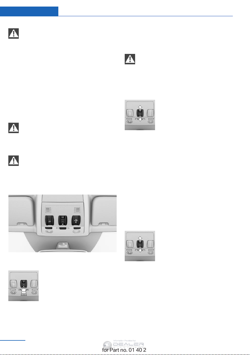
Safety switch
With the safety switch, the rear windows are
prevented from being opened or closed via the
switches in the rear passenger area, such as
by children.
Press the button.
The LED lights up if the safety function is
switched on.
43
Page 46
Controls Opening and closing
Information Provided by:
Safety switch for rear operation
Press the safety switch when transport‐
ing children in the rear; otherwise, injury may
result if the windows are closed without super‐
vision.◀
Panoramic glass sunroof
General information
The glass sunroof and the sliding visor can be
operated together or separately using the
switch.
Danger of pinching
Monitor the closing process and make
sure that the closing path of the glass sunroof
is clear; otherwise, injuries may result.◀
Take the remote control with you
Take the remote control with you when
leaving the vehicle so that children, for exam‐
ple, cannot operate the roof and injure them‐
selves.◀
Pressing the switch again
closes the sliding visor al‐
most completely.
Do not use force to close the sliding visor
Do not use force to close the sliding visor
with the glass sunroof in its tilted position, oth‐
erwise the mechanism will be damaged.
◀
Opening/closing the sliding visor
▷ Press the switch in the de‐
sired direction to the resist‐
ance point and hold it there.
The sliding visor moves
while the switch is being
held.
▷ Press the switch in the desired direction
past the resistance point.
The sliding visor moves automatically.
Pressing the switch again stops the mo‐
tion.
Opening/closing the glass sunroof
With the sliding visor open, proceed as descri‐
bed under Sliding visor.
Tilting the glass sunroof
Press the switch briefly.
▷ The closed roof is tilted and
the sliding visor opens
slightly.
▷ The opened roof closes until
it is in its tilted position. The
sliding visor stays com‐
pletely open.
44
Online Edition for Part no. 01 40 2 954 052 - II/15
Opening/closing the glass sunroof and
sliding visor together
Press the switch twice in the de‐
sired direction past the resist‐
ance point.
The glass sunroof and sliding vi‐
sor move together. Pressing the
switch again stops the motion.
Convenient operation, refer to page 34, via the
remote control or the door lock.
Convenient closing, refer to page 39, with
Comfort Access.
Page 47
Opening and closing Controls
Information Provided by:
Comfort position
In the comfort position, the roof is not fully
open. This reduces wind noise in the passen‐
ger compartment.
Each time the glass sunroof is opened or
closed all the way, it stops in the comfort posi‐
tion. If desired, continue the motion following
this with the switch.
After the ignition is switched off
The roof can still be operated for approx. 1 mi‐
nute, as long as no door has been opened.
Pinch protection system
If the closing force when closing the glass sun‐
roof exceeds a certain value, the closing move‐
ment is stopped, beginning at approximately
the middle of the opening in the roof, or from
the tilted position during closing.
The glass sunroof opens again slightly.
Danger of pinching even with pinch pro‐
tection
Despite the pinch protection system, check
that the roof's closing path is clear; otherwise,
the closing action may not be interrupted in
certain extreme situations, such as when thin
objects are present.◀
Initialization after a power failure
After a power failure, it may only possible to tilt
the roof.
Have the system initialized by your service
center.
Closing without the pinch protection
system
For example, if there is an external danger, pro‐
ceed as follows:
1. Press the switch forward beyond the re‐
sistance point and hold.
Pinch protection is limited and the roof re‐
opens slightly if the closing force exceeds
a certain value.
2. Press the switch forward again beyond the
resistance point and hold until the roof
closes without pinch protection.
Online Edition for Part no. 01 40 2 954 052 - II/15
45
Page 48
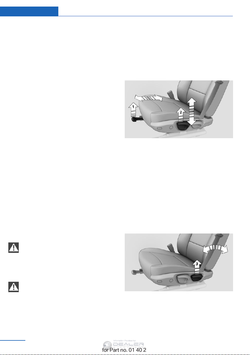
Controls Adjusting
Information Provided by:
Adjusting
Vehicle equipment
This chapter describes all series equipment as
well as country-specific and special equipment
offered for this model series. Therefore, it also
describes equipment that may not be found in
your vehicle, for instance due to the selected
special equipment or the country version. This
also applies to safety-related functions and
systems.
When using the features and systems descri‐
bed here, adhere to local regulations.
Sitting safely
The ideal seating position can make a vital
contribution to relaxed, fatigue-free driving.
The seating position plays an important role in
an accident in combination with:
▷ Safety belts, refer to page 48.
▷ Head restraints, refer to page 49.
▷ Airbags, refer to page 90.
Seats
Note before adjusting
Do not adjust the seat while driving
Never attempt to adjust the driver's seat
while driving. The seat could respond with un‐
expected movement and the ensuing loss of
vehicle control could lead to an accident.
◀
nate the protection normally provided by the
◀
belt.
Adjusting manually
Forward/backward
Pull lever 1 and slide the seat into the desired
position.
After releasing the lever, move the seat for‐
ward or back slightly to make sure it engages
properly.
Height
Pull lever 2 and apply your weight to the seat
or lift it off, as necessary.
Backrest tilt
Do not incline the backrest too far to the
rear
Do not incline the backrest on the front pas‐
senger side too far to the rear during driving.
Otherwise, there is the danger of sliding under
the safety belt in an accident. This would elimi‐
46
Online Edition for Part no. 01 40 2 954 052 - II/15
Pull lever 3 and apply your weight to the back‐
rest or lift it off, as necessary.
Page 49
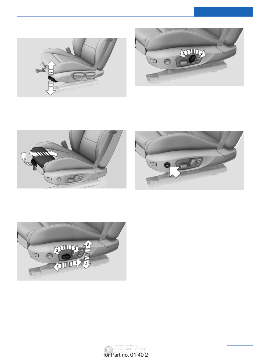
Seat tilt
Information Provided by:
Pull the lever and apply your weight to the seat
or lift it off, as necessary.
Adjusting Controls
4 Backrest
The head restraint can be adjusted manually,
refer Head restraints below.
Thigh support
Pull the lever and move the thigh support for‐
ward or back.
Adjusting electrically
1 Forward/backward
2 Height
3 Seat tilt
Lumbar support
You can also adjust the contour of the backrest
to obtain additional support in the lumbar re‐
gion.
The upper hips and spinal column receive sup‐
plementary support to help you maintain a re‐
laxed, upright sitting position.
▷ Increase or decrease curvature:
Press front or rear section of switch.
▷ Shift curvature up or down:
Press upper or lower section of switch.
Online Edition for Part no. 01 40 2 954 052 - II/15
47
Page 50
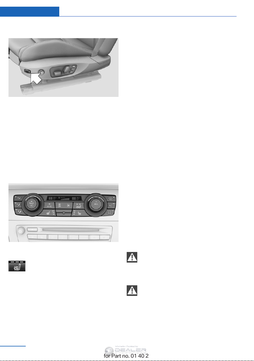
Controls Adjusting
Information Provided by:
Backrest width
The width of the backrest can be changed with
the side wings to adjust the side support to
your own needs.
Press front or rear section of switch.
The backrest width decreases or increases.
Adjusting the rear seat backrests
Adjusting the backrest tilt, refer to page 121.
Seat heating
The LEDs go out.
The temperature is reduced, if need be, down
to no heat in order to reduce the load on the
battery. The LEDs remain lit.
Safety belts
General information
Always make sure that safety belts are being
worn by all occupants before driving away.
Although airbags enhance safety by providing
added protection, they are not a substitute for
safety belts.
Seats with safety belt
▷ The shoulder strap's anchorage point will
be correct for adult seat occupants of ev‐
ery build if the seat is correctly adjusted.
▷ The two rear safety belt buckles integrated
into the rear seat are for passengers sitting
on the left and right.
▷ The belt buckle embossed with the word
CENTER is intended exclusively for use by
passengers riding in the center position.
▷ If the middle safety belt is used in the rear,
the left backrest must be locked, refer to
page 121; otherwise, the safety belt will
not have a restraining effect.
Switching on
Press the button once for each tem‐
perature level.
The maximum temperature is reached when
three LEDs are lit.
If the trip is continued within approx. 15 mi‐
nutes, the seat heating is activated automati‐
cally with the temperature set last.
Switching off
Press the button longer.
48
Online Edition for Part no. 01 40 2 954 052 - II/15
Notes
One person per safety belt
Never allow more than one person to
wear a single safety belt. Never allow infants or
small children to ride on a passenger's lap.
Putting on the belt
Lay the belt, without twisting, snugly
across the lap and shoulders, as close to the
body as possible. Make sure that the belt lies
low around the hips in the lap area and does
not press on the abdomen. Otherwise, the belt
can slip over the hips in the lap area in a frontal
impact and injure the abdomen.
◀
Page 51
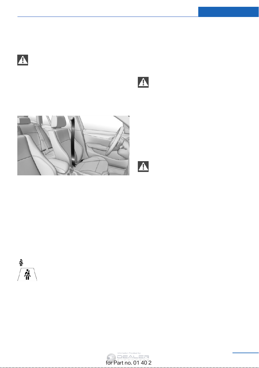
Adjusting Controls
Information Provided by:
The safety belt must not lie across the neck,
rub on sharp edges, be routed over solid or
breakable objects, or be pinched.
Reduction of restraining effect
Avoid wearing clothing that prevents the
belt from fitting properly, and pull the shoulder
belt periodically to readjust the tension across
your lap; otherwise, the retention effect of the
safety belt may be reduced.◀
◀
Buckling the belt
Make sure you hear the latch plate engage in
the belt buckle.
Unbuckling the belt
1. Hold the belt firmly.
2. Press the red button in the belt buckle.
3. Guide the belt back into its reel.
Safety belt reminder for the driver's
and front passenger seat
The indicator lamp lights up and a
signal sounds. In addition, a message
appears on the Control Display.
Check whether the safety belt has
been fastened correctly.
Damage to safety belts
In the case of strain caused by accidents or
damage:
Have the safety belts, including the safety belt
tensioners, replaced and have the belt anchors
checked.
Checking and replacing safety belts
Have the work performed only by your
service center; otherwise, it cannot be ensured
that this safety feature will function properly.
◀
Head restraints
Correctly adjusted head restraints
A correctly adjusted head restraint reduces the
risk of spinal injury in the event of an accident.
Adjusting the head restraint
Correctly adjust the head restraints of all
occupied seats; otherwise, there is an in‐
creased risk of injury in an accident.◀
Height
Adjust the head restraint so that its center is
approx. at ear level.
Distance
Adjust the distance so that the head restraint
is as close as possible to the back of the head.
The safety belt reminder is active at speeds
above approx. 5 mph/8 km/h. It can also be ac‐
tivated if objects are placed on the front pas‐
senger seat.
Online Edition for Part no. 01 40 2 954 052 - II/15
49
Page 52
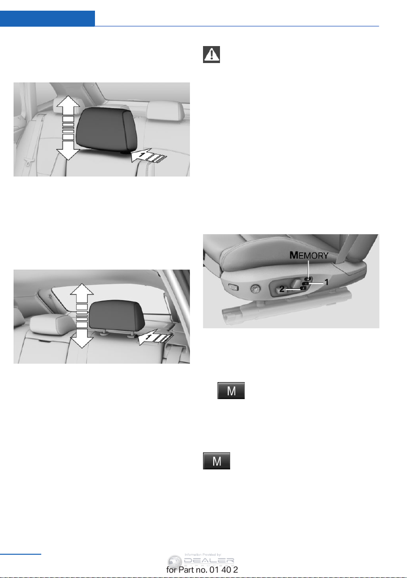
Controls Adjusting
Information Provided by:
Front
Height adjustment
▷ To raise: pull.
▷ To lower: press the button, arrow 1, and
push the head restraint down.
Rear
Height adjustment
Before transporting passengers
Reinstall the head restraint before trans‐
porting anyone in the seat; otherwise, the pro‐
tective function of the head restraint is unavail‐
able.
◀
Seat and mirror memory
General information
Two different driver's seat and exterior mirror
positions can be stored and retrieved.
The adjustment of the backrest width and the
lumbar support is not stored in the memory.
Storing
▷ To raise: pull.
▷ To lower: press button, arrow 1, and push
headrest down.
The height of the middle head restraint cannot
be adjusted.
Removing at the front and rear
Only remove the head restraint if no one will be
sitting in the seat in question.
1. Pull upward as far as possible.
2. Press the button, arrow 1, and completely
pull out the head restraint with the rear
seat backrest folded forward slightly.
50
Online Edition for Part no. 01 40 2 954 052 - II/15
1. Switch on the radio ready state or the igni‐
tion, refer to page 59.
2. Adjust the seat and exterior mirrors to the
desired positions.
3. Press the button. The LED in the
button lights up.
4. Press the desired memory button 1 or 2.
The LED goes out.
If the M button is pressed accidentally:
Press the button again. The LED goes
out.
Page 53
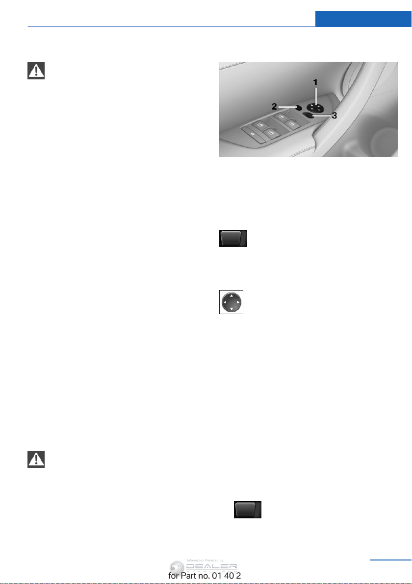
Adjusting Controls
Information Provided by:
Calling up settings
Do not retrieve the memory setting while
driving
Do not retrieve the memory setting while driv‐
ing, as an unexpected seat movement could
result in an accident.
◀
Comfort function
1. Open the driver's door after unlocking or
switch on the radio ready state, refer to
page 59.
2. Briefly press the desired memory but‐
ton 1 or 2.
The seat is automatically moved to the stored
position.
The procedure stops when a switch for setting
the seat or one of the memory buttons is
pressed.
Safety mode
1. Close the driver's door and switch the igni‐
tion on or off, refer to page 59.
2. Press and hold the desired memory button
1 or 2 until the setting procedure is com‐
pleted.
At a glance
1 Adjusting
2 Fold in and out
3 Left/right, Automatic Curb Monitor
Selecting a mirror
To change over to the other mirror:
Slide the mirror changeover switch.
Adjusting electrically
The setting corresponds to the direc‐
tion in which the button is pressed.
Saving positions
Seat and mirror memory, refer to page 50.
Mirrors
Exterior mirrors
General information
The mirror on the passenger side is more
curved than the driver's mirror.
Estimating distances correctly
Objects reflected in the mirror are closer
than they appear. Do not estimate the distance
to the traffic behind you based on what you
see in the mirror, as this will increase your risk
of an accident.
◀
Online Edition for Part no. 01 40 2 954 052 - II/15
Adjusting manually
If an electrical malfunction occurs, for example,
press the edges of the mirror glass.
Automatic Curb Monitor
When the reverse gear is engaged, the mirror
glass tilts downward slightly on the front pas‐
senger side. This improves your view of the
curb and other low-lying obstacles when park‐
ing, for example.
Activating
1.
Slide the mirror changeover switch
to the driver's side mirror position.
51
Page 54
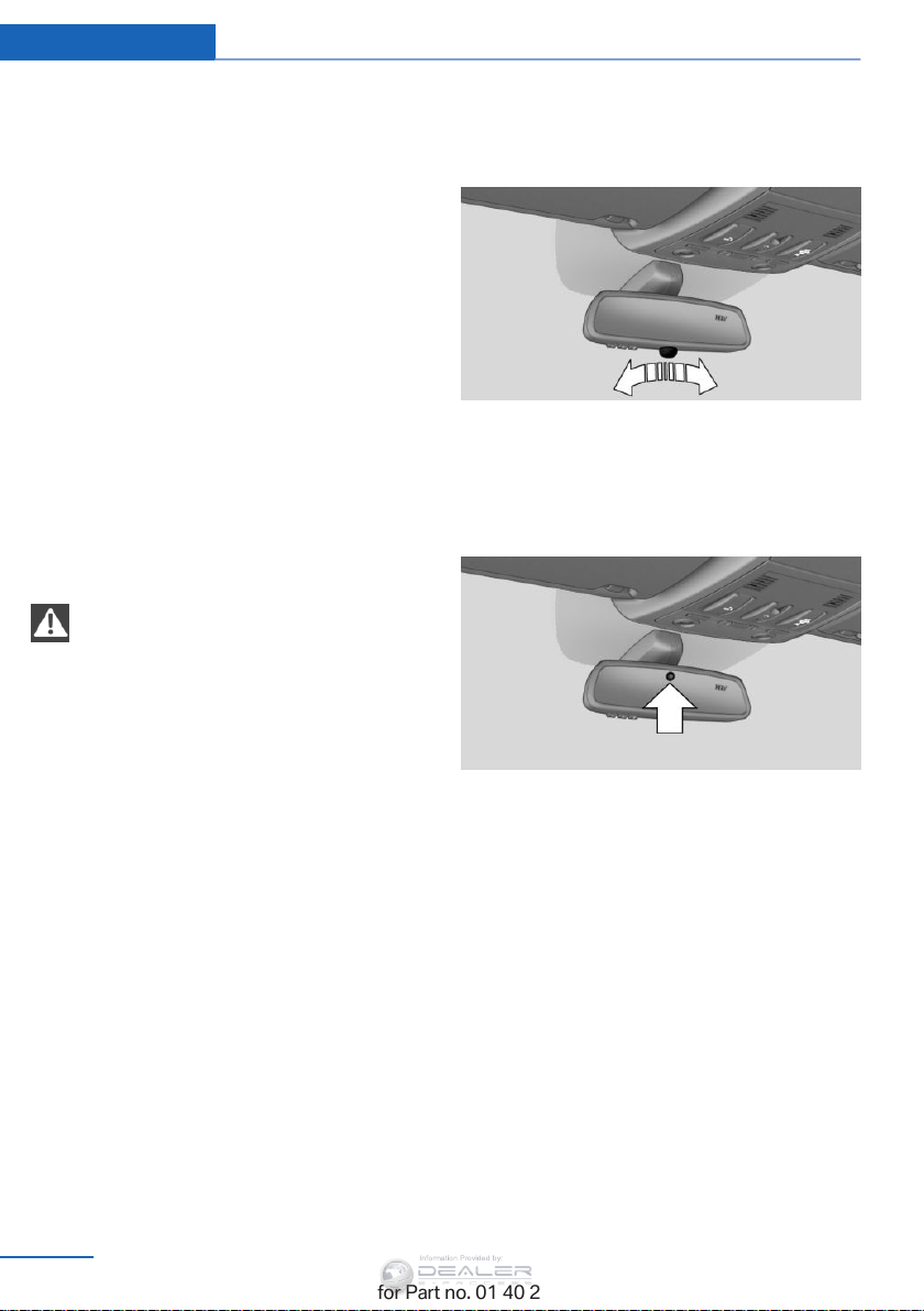
Controls Adjusting
Information Provided by:
2. Shift into reverse or engage transmission
position R.
Deactivating
Slide the mirror changeover switch to the pas‐
senger side mirror position.
Fold in and out
Press button 2.
Possible up to approx. 15 mph/20 km/h.
For example, this is advantageous
▷ In car washes.
▷ In narrow streets.
▷ For folding back mirrors that were folded
away manually.
Mirrors that were folded in are folded out auto‐
matically at a speed of approx.
25 mph/40 km/h.
Fold in the mirror in a car wash
Before entering an automatic car wash,
fold in the exterior mirrors by hand or with the
button; otherwise, they could be damaged, de‐
pending on the width of the vehicle.
◀
Interior rearview mirror
Reducing the blinding effect
From behind when driving at night: turn the
knob.
Interior and exterior mirrors,
automatic dimming feature
Automatic heating
Depending on the external temperature, both
exterior mirrors are automatically heated when
the engine is running or the ignition is
switched on.
52
Online Edition for Part no. 01 40 2 954 052 - II/15
Two photocells are used for control:
▷ In the mirror glass, see arrow.
▷ On the back of the mirror.
For proper operation:
▷ Keep the photocells clean.
▷ Do not cover the area between the inside
rearview mirror and the windshield.
Page 55
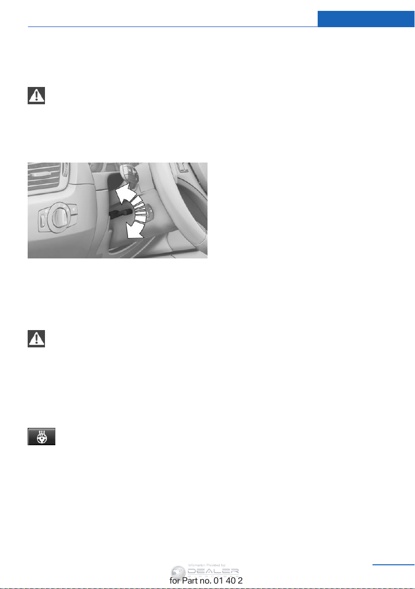
Steering wheel
Information Provided by:
General information
Do not adjust while driving
Do not adjust the steering wheel while
driving; otherwise, an unexpected movement
could result in an accident.
Adjusting
1. Fold the lever down.
2. Move the steering wheel to the preferred
height and angle to suit your seating posi‐
tion.
3. Fold the lever back.
Do not use force to swing the lever back.
Do not use force to swing the lever back
up; otherwise, the mechanism will be dam‐
aged.
◀
◀
Adjusting Controls
Steering wheel heating
Switching on/off
Press the button.
▷ On: the LED lights up.
▷ Off: the LED goes out.
Online Edition for Part no. 01 40 2 954 052 - II/15
53
Page 56

Controls Transporting children safely
Information Provided by:
Transporting children safely
Vehicle equipment
This chapter describes all series equipment as
well as country-specific and special equipment
offered for this model series. Therefore, it also
describes equipment that may not be found in
your vehicle, for instance due to the selected
special equipment or the country version. This
also applies to safety-related functions and
systems.
When using the features and systems descri‐
bed here, adhere to local regulations.
The right place for children
Note
Children in the vehicle
Do not leave children unattended in the
vehicle; otherwise, they could endanger them‐
selves and other persons, e.g., by opening the
◀
doors.
Children should always be in the rear
Accident research shows that the safest place
for children is on the rear seat.
Transporting children in the rear
Transport children younger than
13 years of age or shorter than 5 ft/150 cm in
the rear only, using child restraint fixing sys‐
tems suitable for the age, weight, and height of
the child; otherwise, there is an increased risk
of injury in an accident.
Children 13 years of age or older must wear a
safety belt as soon as a suitable child restraint
fixing system can no longer be used, due to
their age, weight and size.◀
Children on the front passenger seat
Should it be necessary to use a child restraint
fixing system on the front passenger seat,
make sure that the front and side airbags on
the front passenger side are deactivated. Auto‐
matic deactivation of front passenger airbags,
refer to page 91.
Deactivating the front passenger airbags
If a child restraint fixing system is used in
the front passenger seat, the front passenger
airbags must be deactivated; otherwise, there
is an increased risk of injury to the child when
the airbags are triggered, even with a child re‐
straint fixing system.◀
Installing child restraint fixing systems
Notes
Manufacturer's information for child re‐
straint fixing systems
To select, mount and use child restraint fixing
systems, observe the information provided by
the system manufacturer; otherwise, the pro‐
tective effect can be impaired.
On the front passenger seat
After installing a child restraint fixing system
on the front passenger seat, ensure that the
front and side airbags on the front passenger
side are deactivated.
Deactivating the front passenger airbags
If a child restraint fixing system is used in
the front passenger seat, the front passenger
airbags must be deactivated; otherwise, there
is an increased risk of injury to the child when
the airbags are triggered, even with a child re‐
straint fixing system.◀
◀
54
Online Edition for Part no. 01 40 2 954 052 - II/15
Page 57
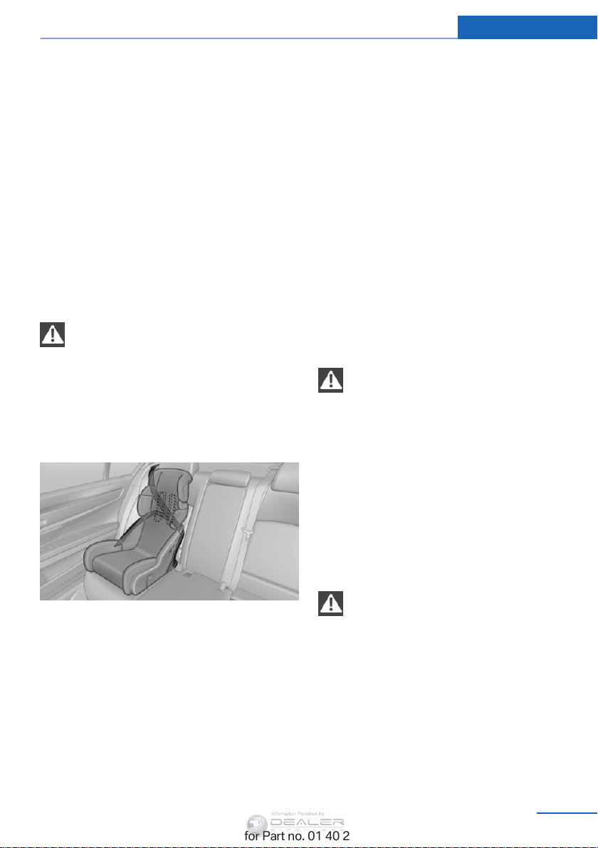
Transporting children safely Controls
Information Provided by:
Seat position and height
Before installing a child restraint fixing system,
move the front passenger seat as far back as
possible and adjust its height to the highest
position to obtain the best possible position for
the belt and to offer optimal protection in the
event of an accident.
Do not change the seat position and height af‐
ter this.
Backrest width
Before mounting a child restraint fixing system
on the front passenger seat, open the backrest
width, refer to page 48, completely. Do not
change the backrest width after this.
Backrest width for the child seat
Before installing a child restraint fixing
system in the front passenger seat, the back‐
rest width must be opened completely. Do not
change the adjustment after this; otherwise,
the stability of the child seat will be reduced.
◀
Child seat security
3. Allow the belt webbing to be pulled in and
pull it taut against the child restraint fixing
system. The safety belt is locked.
Unlocking the safety belt
1. Open the belt buckle.
2. Remove the child restraint fixing system.
3. Allow the belt webbing to be pulled in com‐
pletely.
LATCH child restraint fixing system
LATCH: Lower Anchors and Tether for Chil‐
dren.
Note
Manufacturer's information for LATCH
child restraint fixing systems
To mount and use the LATCH child restraint
fixing systems, observe the operating and
safety information from the system manufac‐
turer; otherwise, the level of protection may be
reduced.◀
The rear safety belts and the safety belt for the
front passenger can be locked to prevent ex‐
tension in order to permit attachment of child
restraint fixing systems.
Locking the safety belt
1. Pull out the belt webbing completely.
2. Secure the child restraint fixing system
with the belt.
Online Edition for Part no. 01 40 2 954 052 - II/15
Mounts for the lower LATCH anchors
The lower anchors may be used to attach the
CRS to the vehicle seat up to a combined child
and CRS weight of 65 lb/30 kg when the child
is restrained by the internal harnesses.
Correctly engage the lower LATCH an‐
chors
Make sure that the lower LATCH anchors have
properly engaged and that the child restraint
fixing system is resting snugly against the
backrest; otherwise, the degree of protection
offered may be reduced.
◀
55
Page 58
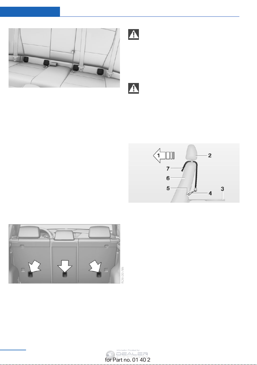
Controls Transporting children safely
Information Provided by:
The mounts for the lower LATCH anchors are
located behind the indicated cover caps.
Before mounting the LATCH child restraint fix‐
ing system, pull the belt away from the child
restraint fixing system.
Mounting LATCH child restraint fixing
systems
1. Mount the child restraint fixing system; re‐
fer to the operating instructions of the sys‐
tem.
2. Ensure that both LATCH anchors are prop‐
erly connected.
LATCH mounting points
Only use the mounting points for the up‐
per LATCH retaining strap to secure child re‐
straint systems; otherwise, the mounting
points could be damaged.
◀
Retaining strap guide
Retaining strap
Make sure the upper retaining strap does
not run over sharp edges and is not twisted as
it passes to the top anchor. Otherwise, the
strap will not properly secure the child restraint
fixing system in the event of an accident.◀
Outer rear seats
Child restraint fixing system with a
tether strap
Mounting points
There are three mounting points, see arrows,
for the upper retaining strap of LATCH child
restraint fixing systems.
56
Online Edition for Part no. 01 40 2 954 052 - II/15
1 Direction of travel
2 Head restraint
3 Cargo area floor
4 Hook for upper retaining strap
5 Mounting point/eye
6 Backrest
7 Upper retaining strap
When using the cargo cover, pass the upper
retaining strap between the rear seat backrest
and the cargo cover.
Page 59
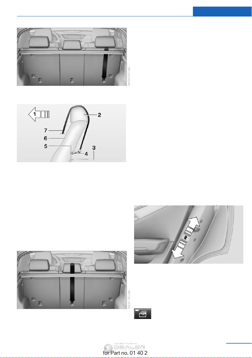
Center rear seat
Information Provided by:
1 Direction of travel
2 Head restraint
3 Cargo area floor
4 Hook for upper retaining strap
5 Mounting point/eye
6 Backrest
7 Upper retaining strap
Transporting children safely Controls
Attaching the upper retaining strap to
the mounting point
On outer rear seats:
1. Slide the head restraint upward.
2. Guide the upper retaining strap between
the supports of the head restraint.
3. Attach the hook of the retaining strap to
the mounting eye.
4. Pull the retaining strap taut.
On center rear seat:
1. Route the upper retaining strap over the
middle of the head restraint.
2. Attach the hook of the retaining strap to
the mounting eye.
3. Pull the retaining strap taut until it com‐
presses the cushion of the head restraint,
thus preventing the strap from sliding off.
Locking the doors and windows
Rear doors
When using the cargo cover, pass the upper
retaining strap between the rear seat backrest
and the cargo cover.
Online Edition for Part no. 01 40 2 954 052 - II/15
Push the locking lever on the rear doors down.
The door can now be opened from the outside
only.
Safety switch for the rear
Press the button on the driver's door if
children are being transported in the
rear.
57
Page 60

Controls Transporting children safely
Information Provided by:
This locks the rear window switches so that
the windows cannot be operated from the rear:
safety switch, refer to page 43.
58
Online Edition for Part no. 01 40 2 954 052 - II/15
Page 61
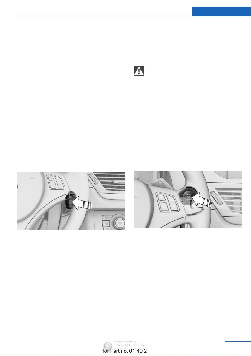
Driving
Information Provided by:
Driving Controls
Vehicle equipment
This chapter describes all series equipment as
well as country-specific and special equipment
offered for this model series. Therefore, it also
describes equipment that may not be found in
your vehicle, for instance due to the selected
special equipment or the country version. This
also applies to safety-related functions and
systems.
When using the features and systems descri‐
bed here, adhere to local regulations.
Ignition lock
Insert the remote control into the
ignition lock
Removing the remote control from the
ignition lock
Do not forcibly pull the remote control
out of the ignition lock
Do not forcibly pull the remote control out of
the ignition lock as this may cause damage.
Before removing the remote control, push it all
the way in to release the locking mechanism.
▷ The ignition is switched off if it was on.
◀
Automatic transmission
You can only take out the remote control if
transmission position P is engaged: interlock.
Start/Stop button
Insert the remote control all the way into the
ignition lock.
▷ Radio ready state is switched on. Individual
electrical consumers can operate.
Comfort Access
If the car is equipped with Comfort Access,
only insert the remote control into the ignition
lock, refer to page 39, under special circum‐
stances.
Online Edition for Part no. 01 40 2 954 052 - II/15
Pressing the Start/Stop button switches the
ignition on or off and starts the engine.
The engine starts if the brake pedal is pressed
when you press the Start/Stop button.
Radio ready state
Individual electrical consumers can operate.
The time and the external temperature are dis‐
played in the instrument cluster.
Radio ready state is switched off automatically:
▷ When the remote control is removed from
the ignition lock.
59
Page 62
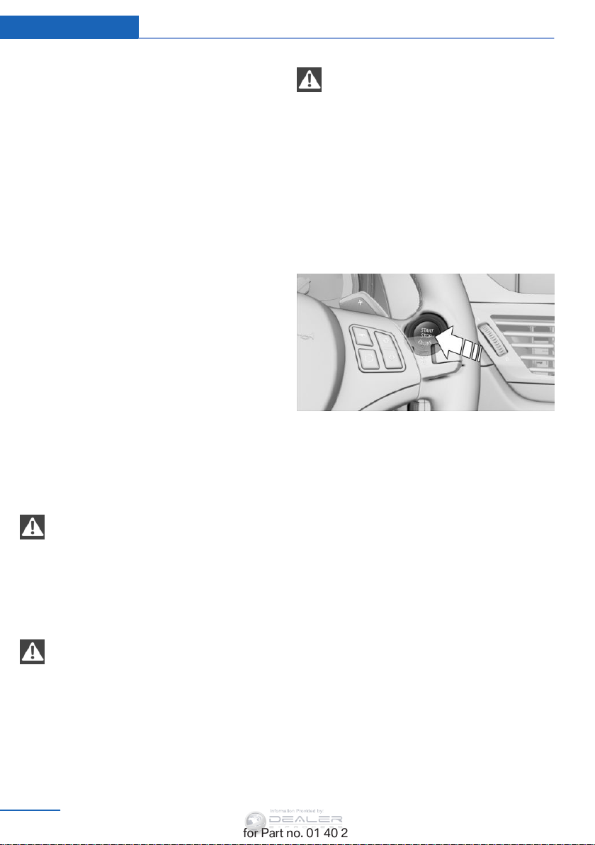
Controls Driving
Information Provided by:
▷ In cars with Comfort Access, refer to
page 39, by touching the surface above the
door lock.
Ignition on
All electrical consumers can operate. The od‐
ometer and trip odometer are displayed in the
instrument cluster.
To save battery power when the engine is off,
switch off the ignition and any unnecessary
electronic systems/power consumers.
Radio ready state and ignition off
All indicator and warning lamps as well as dis‐
plays in the instrument cluster go out.
Automatic transmission, 8-gear
In certain situations, transmission position P is
engaged automatically. To make it possible for
the vehicle to roll, such as in an automatic car
wash, follow the instructions in Car washes, re‐
fer to page 263.
Starting the engine
General information
Enclosed areas
Do not let the engine run in enclosed
areas; otherwise, breathing of exhaust fumes
may lead to loss of consciousness and death.
The exhaust gases contain carbon monoxide,
an odorless and colorless but highly toxic
gas.◀
Frequent starting in quick succession
Avoid repeated futile attempts at starting
the car and avoid starting the car frequently in
quick succession. Otherwise, the fuel is not
burned or is inadequately burned, and there is
the danger of overheating and damaging the
catalytic converter.◀
Do not wait for the engine to warm-up while
the vehicle remains stationary. Start driving
right away, but at moderate engine speeds.
Starting the engine
Automatic transmission
Remote control in the ignition lock or, with
Comfort Access, inside the vehicle, refer to
page 39.
1. Depress the brake pedal.
2. Engage transmission position P if neces‐
sary.
3. Press the Start/Stop button.
The ignition is activated automatically for a
certain time and is stopped as soon as the en‐
gine starts.
Unattended vehicle
Do not leave the car unattended with the
engine running; otherwise, it presents a poten‐
tial source of danger.
Before leaving the car with the engine running,
shift to neutral or engage transmission posi‐
tion P and set the parking brake firmly; other‐
wise, the vehicle may begin to roll.
60
Online Edition for Part no. 01 40 2 954 052 - II/15
◀
Page 63
Driving Controls
Information Provided by:
Engine stop
General information
Take the remote control with you
Take the remote control with you when
leaving the vehicle so that children, for exam‐
ple, cannot operate the windows and injure
themselves.◀
Set the parking brake and further secure
the vehicle as required
Set the parking brake firmly when parking; oth‐
erwise, the vehicle may roll. On steep upward
and downward inclines, further secure the ve‐
hicle, for example, by turning the steering
wheel in the direction of the curb.
Before driving into a car wash
To make it possible for the vehicle to roll in an
automatic car wash, follow the information on
Washing in automatic car washes, refer to
page 263.
Switching off the engine
Automatic transmission
1. Engage transmission position P with the
vehicle stopped.
2. Press the Start/Stop button.
3. Set the parking brake firmly.
4. Remove the remote control from the igni‐
tion lock, refer to page 59.
◀
engine starts automatically when you wish to
drive away.
Automatic operation
The automatic engine Start/Stop function is
operational after each engine start. It is acti‐
vated whenever you drive forward faster than
3 mph/5 km/h.
Automatic engine stop
The engine is switched off automatically dur‐
ing a stop under the following conditions:
Automatic transmission:
▷ The selector lever is in transmission posi‐
tion D.
▷ The brake pedal remains depressed while
the vehicle is at a standstill.
▷ The driver's safety belt is fastened or the
driver's door is closed.
When the engine is switched off, the air vol‐
ume of the automatic climate control is re‐
duced.
Indicator light in the instrument
cluster
The indicator lamp lights up when the
Auto Start/Stop function is ready to
start the engine automatically.
The indicator lamp lights up if the re‐
quirements for an automatic engine
stop are not fulfilled.
Automatic Engine Start/Stop Function
The concept
The Auto Start/Stop function helps save fuel.
The system switches off the engine during a
stop, for instance in congestion or at traffic
lights. The ignition remains switched on. The
Online Edition for Part no. 01 40 2 954 052 - II/15
Note
The engine is not switched off automatically in
the following situations:
▷ External temperature too low.
▷ High external temperature and operation of
the automatic climate control.
▷ The interior is not yet heated or cooled as
much as desired.
61
Page 64
Controls Driving
Information Provided by:
▷ The engine is not yet at operating temper‐
ature.
▷ Sharp steering angle or the steering wheel
is being turned.
▷ After driving in reverse.
▷ Fogging of the windows when the auto‐
matic climate control is switched on.
▷ Vehicle battery charge is very low.
▷ Hood is unlocked.
▷ HDC is activated.
▷ Stop-and-go traffic.
▷ The selector lever is in position N or M/S.
The indicator lamp is lit.
Parking the vehicle during an
automatic engine stop
The vehicle can be parked safely during an au‐
tomatic engine stop, such as when you wish to
leave the vehicle.
1. Press the Start/Stop button. The ignition is
switched off. The Auto Start/Stop function
is deactivated.
Automatic transmission: transmission po‐
sition P is engaged automatically.
2. Set the parking brake.
Start the engine as usual using the Start/Stop
button.
Automatic engine start
The engine starts automatically under the fol‐
lowing conditions to enable the driver to drive
away:
▷ Automatic transmission:
The brake pedal is released.
After the engine starts, accelerate as usual.
Safety mode
The engine does not start by itself after it is
switched off automatically if any of the follow‐
ing conditions are fulfilled:
▷ The driver's safety belt is unfastened or
the driver's door is open.
▷ Hood was unlocked.
The indicator lamp lights up. A mes‐
sage appears on the Control Display.
The engine can only be started via
the Start/Stop button.
Note
Even if you do not wish to drive away, the stop‐
ped engine still starts automatically in the fol‐
lowing situations:
▷ The interior has heated up strongly with
the cooling function switched on.
▷ The steering wheel is turned.
▷ The vehicle begins to roll.
▷ Automatic transmission: the transmission
position is changed from D to N, R or M/S.
▷ Automatic transmission: the transmission
position is changed from P to N, D, R or
M/S.
▷ Fogging of the windows when the auto‐
matic climate control is switched on.
▷ Vehicle battery charge is very low.
▷ The interior has cooled down strongly with
the heating switched on.
▷ Low braking pressure, such as from de‐
pressing the brake pedal a number of times
consecutively.
Preventing automatic engine stop
with an automatic transmission
The concept
To permit the driver to drive away especially
quickly, such as at intersections, the automatic
engine stop can be actively prevented.
62
Online Edition for Part no. 01 40 2 954 052 - II/15
Page 65
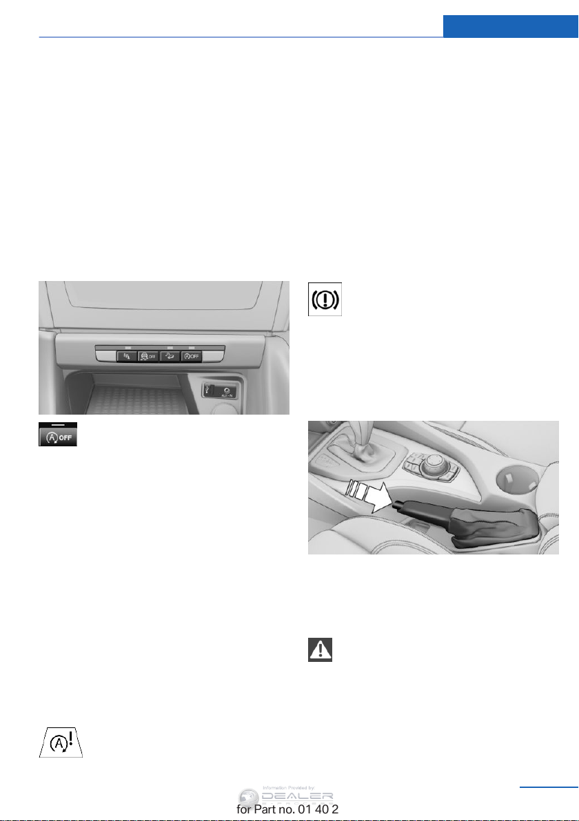
Driving Controls
Information Provided by:
Preventing the engine stop using the
brake pedal
The engine stop can be actively prevented
within one second after the vehicle comes to a
standstill.
▷ Depress the brake pedal briefly and force‐
fully immediately after the vehicle comes to
a standstill.
▷ Then continue depressing the brake pedal
with normal braking force.
Activating/deactivating the system
manually
Press the button.
▷ LED lights up: the Auto Start/Stop function
is deactivated.
The engine is started during an automatic
engine stop.
The engine can only be stopped or started
via the Start/Stop button.
▷ LED goes out: the Auto Start/Stop function
is activated.
matically.A message appears on the Control
Display. It is possible to continue driving. Have
the system checked.
Parking brake
The concept
The parking brake is primarily intended to pre‐
vent the vehicle from rolling while parked; it
brakes the rear wheels.
Indicator lamp
The indicator lamp lights up and an
acoustic signal sounds when driving
away. The parking brake is still set.
Setting
The lever engages automatically.
Releasing
Pull up slightly, press the button, and lower the
lever.
Automatic deactivation
In certain situations, the Auto Start/Stop func‐
tion is deactivated automatically in the interest
of safety, for example if the driver's absence is
detected.
Malfunction
The indicator lamp lights up. The au‐
tomatic engine start/stop function no
longer switches of the engine auto‐
Online Edition for Part no. 01 40 2 954 052 - II/15
Notes
Using the parking brake while driving
If it should become necessary to use the
parking brake while driving, do not pull the
parking brake too forcefully. Keep the button
on the parking brake lever pressed at all times.
Excessive application of the parking brake can
block the rear wheels and lead to fishtailing of
the vehicle.◀
63
Page 66
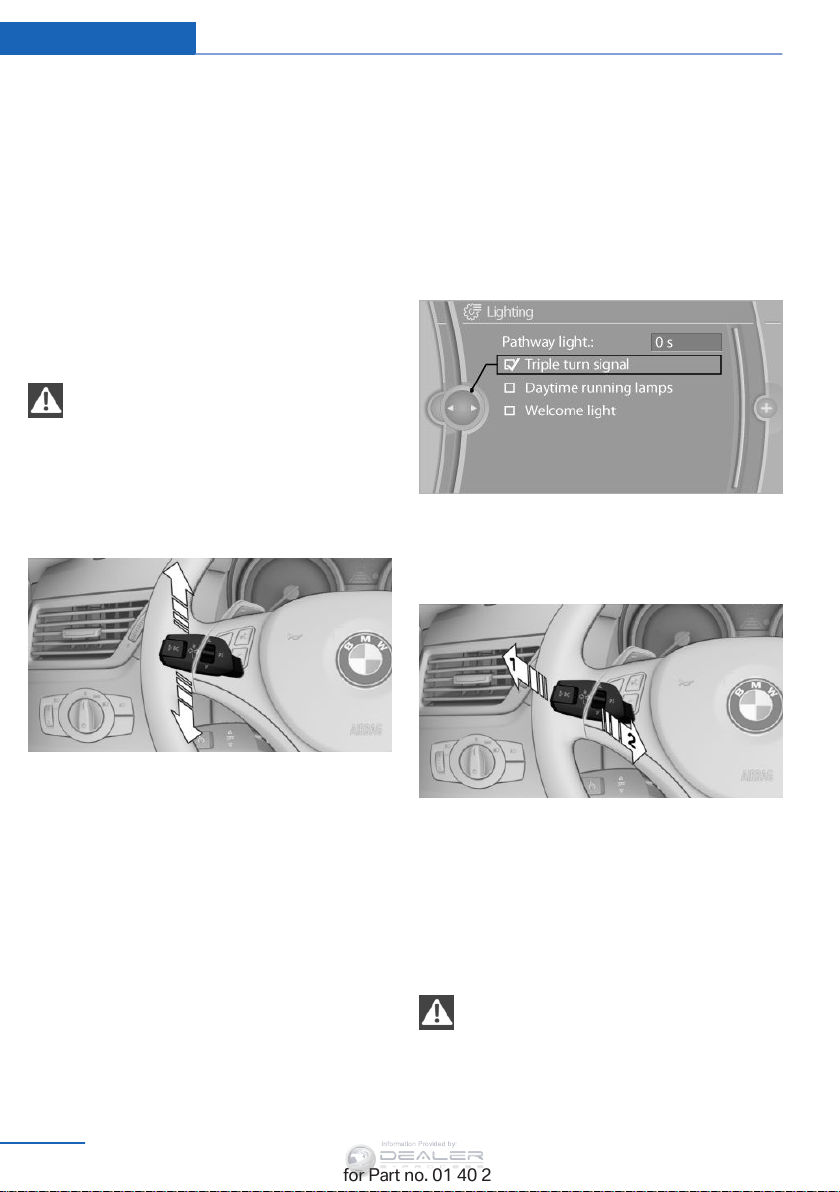
Controls Driving
Information Provided by:
To prevent corrosion and uneven brake action,
lightly apply the parking brake from time to
time when coasting, traffic conditions permit‐
ting.
The brake lights do not light up when the park‐
ing brake is pulled.
Turn signal, high beams, headlamp flasher
Turn signal
Do not fold in the exterior mirrors
While driving and when using the turn
signal/hazard warning flashers, do not fold in
the exterior mirrors; otherwise, the additional
turn signal lamps in the exterior mirrors will not
be in the appropriate position and will be diffi‐
cult to detect.
◀
Triple turn signal activation
Press the lever to the resistance point.
The turn signal flashes three times.
This function can be activated or deactivated:
1. "Settings"
2. "Lighting"
3. "Triple turn signal"
The setting is stored for the remote control
currently in use.
High-beams, headlamp flasher
Press the lever beyond the resistance point.
To switch off manually, press the lever to the
resistance point.
Unusually rapid flashing of the indicator lamp
indicates that a turn signal bulb has failed.
When towing a trailer, the indicator lamp may
also signal the failure of a turn signal bulb on
the trailer.
Signaling a turn briefly
Press the lever to the resistance point and hold
it there for as long as you want the turn signal
to flash.
64
Online Edition for Part no. 01 40 2 954 052 - II/15
1 High-beams
2 Headlamp flasher
Washer/wiper system
Notes
Do not switch on the wipers if frozen
Do not switch on the wipers if they are
frozen onto the windshield; otherwise, the
wiper blades and the windshield wiper motor
may be damaged.
◀
Page 67
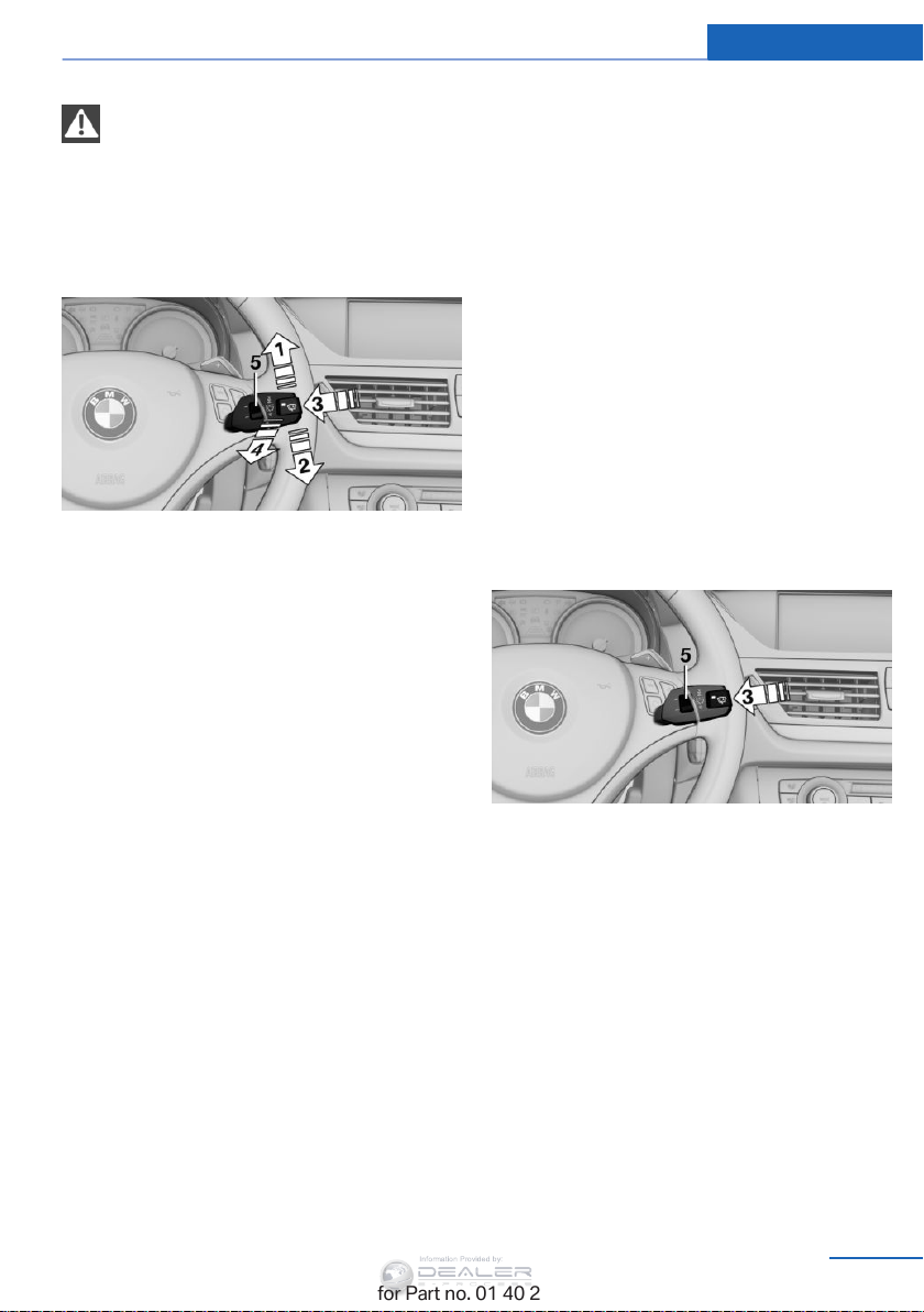
Driving Controls
Information Provided by:
Do not use the wipers on a dry wind‐
shield
Do not use the wipers on a dry windshield; oth‐
erwise, the wiper blades may wear more rap‐
idly or become damaged.
◀
At a glance
1 Switching on wipers
2 Switching off wipers or brief wipe
3 Activating/deactivating intermittent wipe or
the rain sensor
4 Cleaning the windshield and headlights
5 Setting speed for intermittent wipe or sen‐
sitivity of the rain sensor
The lever automatically returns to its initial po‐
sition when released.
▷ Brief wipe: press down once.
▷ To switch off normal wipe: press down
once.
▷ To switch off fast wipe: press down twice.
Intermittent wipe or rain sensor
If the car is not equipped with a rain sensor, the
intermittent-wipe time is a preset.
If the car is equipped with a rain sensor, the
time between wipes is controlled automatically
and depends on the intensity of the rainfall.
The rain sensor is mounted on the windshield,
directly in front of the interior rearview mirror.
Activating intermittent wipe or the
rain sensor
Switching on wipers
Press the wiper lever upward, arrow 1.
The lever automatically returns to its initial po‐
sition when released.
Normal wiper speed
Press up once.
The system switches to operation in the inter‐
mittent mode when the vehicle is stationary.
Fast wiper speed
Press up twice or press once beyond the re‐
sistance point.
The system switches to normal speed when
the vehicle is stationary.
Switching off wipers or brief wipe
Press the wiper lever down, arrow 2.
Online Edition for Part no. 01 40 2 954 052 - II/15
Press the button, arrow 3.
The LED in the steering wheel stalk lights up
and a wiping cycle is started.
Setting intermittent wipe or the
sensitivity of the rain sensor
Turn thumbwheel 5 up or down.
Deactivating intermittent wipe or the
rain sensor
Press the button again, arrow 3.
The LED goes out.
65
Page 68
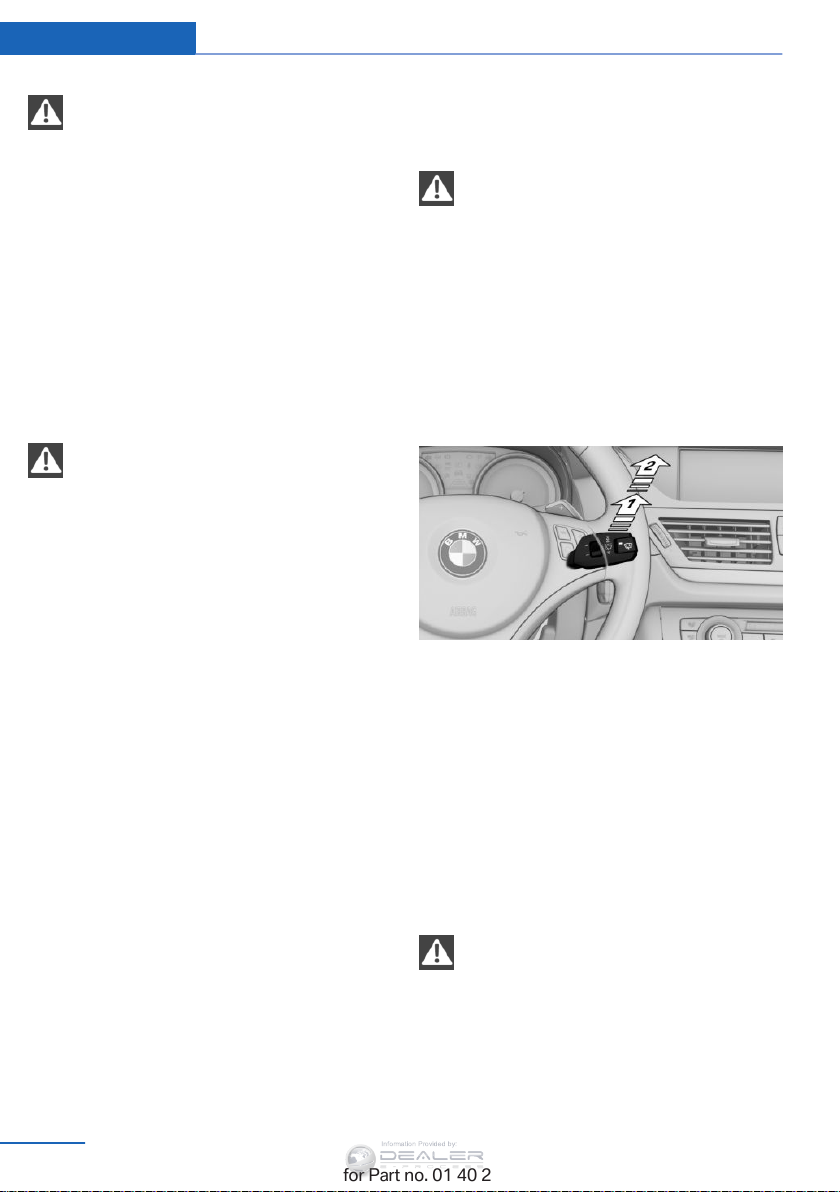
Controls Driving
Information Provided by:
Deactivate the rain sensor in car washes
Deactivate the rain sensor when passing
through an automatic car wash; otherwise,
damage could be caused by undesired wiper
activation.◀
Cleaning the windshield and
headlamps
Pull the lever, arrow 4.
The system sprays washer fluid on the wind‐
shield and activates the wipers briefly.
When the vehicle lighting system is switched
on, the headlights are cleaned at regular and
appropriate intervals.
Do not use the washer system at freezing
temperatures
Do not use the washers if there is any danger
that the fluid will freeze on the windshield; oth‐
erwise, your vision could be obscured. For this
reason, use antifreeze.
Avoid using the washer when the reservoir is
empty; otherwise, you could damage the
pump.◀
Windshield washer nozzles
The windshield washer nozzles are heated au‐
tomatically while the engine is running or the
ignition is switched on.
Fold-out position of the wipers
Required when changing the wiper blades or
under frosty conditions, for example.
1. Switch off the ignition.
2. Under frosty conditions, ensure that the
wiper blades are not frozen onto the wind‐
shield.
3. Press the wiper lever up beyond the point
of resistance and hold it for approx. 3 sec‐
onds, until the wiper remains in a nearly
vertical position.
After the wipers are folded back down, the
washer/wiper system, refer to page 64, must
be reactivated.
Fold the wipers back down
Before switching the ignition on, fold the
wipers back down to the windshield; other‐
wise, the wipers may become damaged when
they are switched on.◀
1. Switch on the ignition.
2. Press the wiper levers down. The wipers
move to their resting position and are
ready for operation.
Rear window wiper
1 Intermittent wipe
When reverse gear is engaged, the system
switches to continuous operation.
2 Cleaning the rear window
The rear window wiper does not move if the
lever is in position 1 before the ignition is
switched on.
To switch on the rear window wiper:
1. Move the lever to its basic position.
2. Select the required position again.
Do not use the washing mechanisms
when the washer fluid reservoir is empty
Do not use washing mechanisms when the
washer fluid reservoir is empty, otherwise you
will damage the washer pump.
◀
66
Online Edition for Part no. 01 40 2 954 052 - II/15
Page 69
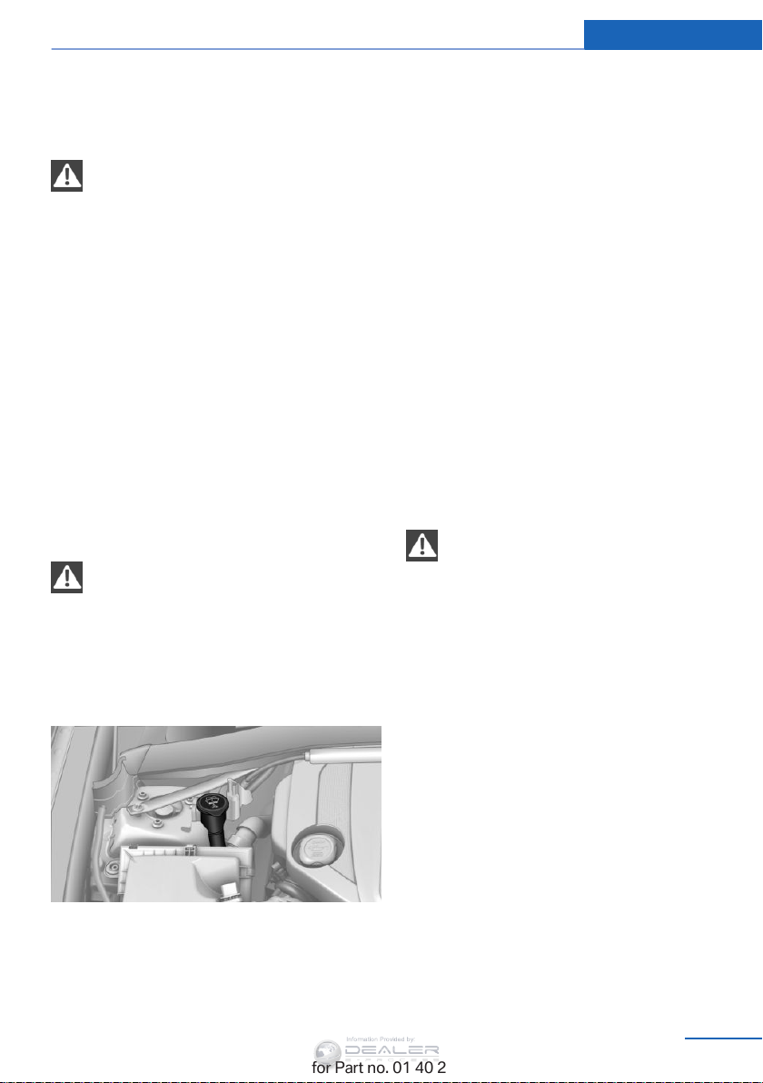
Driving Controls
Information Provided by:
Washer fluid
General information
Antifreeze for washer fluid
Antifreeze is flammable and can cause
injuries if used improperly.
Therefore, keep it away from sources of igni‐
tion.
Only keep it in the closed original container
and inaccessible to children.
Follow the notes and instructions on the con‐
tainer.
United States: The washer fluid mixture ratio is
regulated by the U.S. EPA and many individual
states; do not exceed the allowable washer
fluid dilution ratios limits that apply. Follow the
usage instructions on the washer fluid con‐
tainer. Use BMW's Windshield Washer Con‐
centrate or the equivalent.
Washer fluid reservoir
Adding washer fluid
Only add washer fluid when the engine is
cool, and then close the cover completely to
avoid contact between the washer fluid and
hot engine parts.
Otherwise, there is the danger of fire and a risk
to personal safety if the fluid is spilled.◀
◀
Fill with a mixture of window washing concen‐
trate and tap water; if needed, add antifreeze
according to the manufacturer instructions.
Mix the washer fluid before adding to maintain
the correct mixing ratio.
Do not fill in undiluted window washing con‐
centrate and antifreeze and do not fill in pure
water; this could damage the washer system.
Do not mix window washing concentrate from
different manufacturers; this could cause the
washer nozzles to clog.
Automatic transmission with Steptronic, 6-gear
In addition to the fully automatic mode, gears
can also be shifted manually using Steptronic,
refer to page 68.
Parking the vehicle
Secure the vehicle
Before leaving the vehicle with the en‐
gine running, move the selector lever to posi‐
tion P and set the handbrake; otherwise, the
vehicle will begin moving.
Disengaging the remote control
To remove the remote control from the ignition
lock, first move the selector lever to position P
and switch off the engine: interlock. Remove
the remote control from the ignition lock, refer
to page 59.
◀
All washer nozzles are supplied from one res‐
ervoir.
The recommended minimum filling quantity is
0.2 US gal/1 liter.
Online Edition for Part no. 01 40 2 954 052 - II/15
Selector lever positions
P R N D M/S + –
67
Page 70
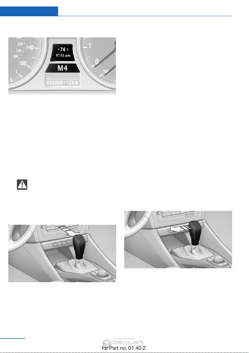
Controls Driving
Information Provided by:
Displays in the instrument cluster
The selector lever position is displayed and the
engaged gear, such as M4, is displayed in
manual mode.
Changing selector lever positions
▷ With the ignition switched on or the engine
running, the selector lever can be moved
out of position P.
▷ When the vehicle is stationary, step on the
brake before shifting out of P or N; other‐
wise, the selector lever is locked: shiftlock.
Press on the brake pedal until you
start driving
To prevent the vehicle from creeping after
you select a driving position, maintain
pressure on the brake pedal until you are
ready to start.
◀
P Park
Select only when the vehicle is stationary. The
rear wheels are locked.
R is Reverse
Select only when the vehicle is stationary.
N is Neutral
Use in automatic car washes, for example. The
vehicle can roll.
D Drive, automatic position
Position for normal vehicle operation. All for‐
ward gears are selected automatically.
Under normal operating conditions, fuel con‐
sumption is lowest when you are driving in po‐
sition D.
Kickdown
Kickdown is used to achieve maximum driving
performance. Press on the accelerator beyond
the resistance point at the full throttle position.
Sport program and manual mode M/S
Activating the Sport program
A lock prevents you from inadvertently engag‐
ing selector lever positions R and P. To cancel
the lock, press the button on the front of the
selector lever, see arrow.
68
Online Edition for Part no. 01 40 2 954 052 - II/15
Move the selector lever from position D toward
the left.
DS is displayed in the instrument cluster.
This position is recommended for a perform‐
ance-oriented driving style.
To deactivate the Sport program or manual
mode M/S, move the selector lever to the right
into position D.
Page 71
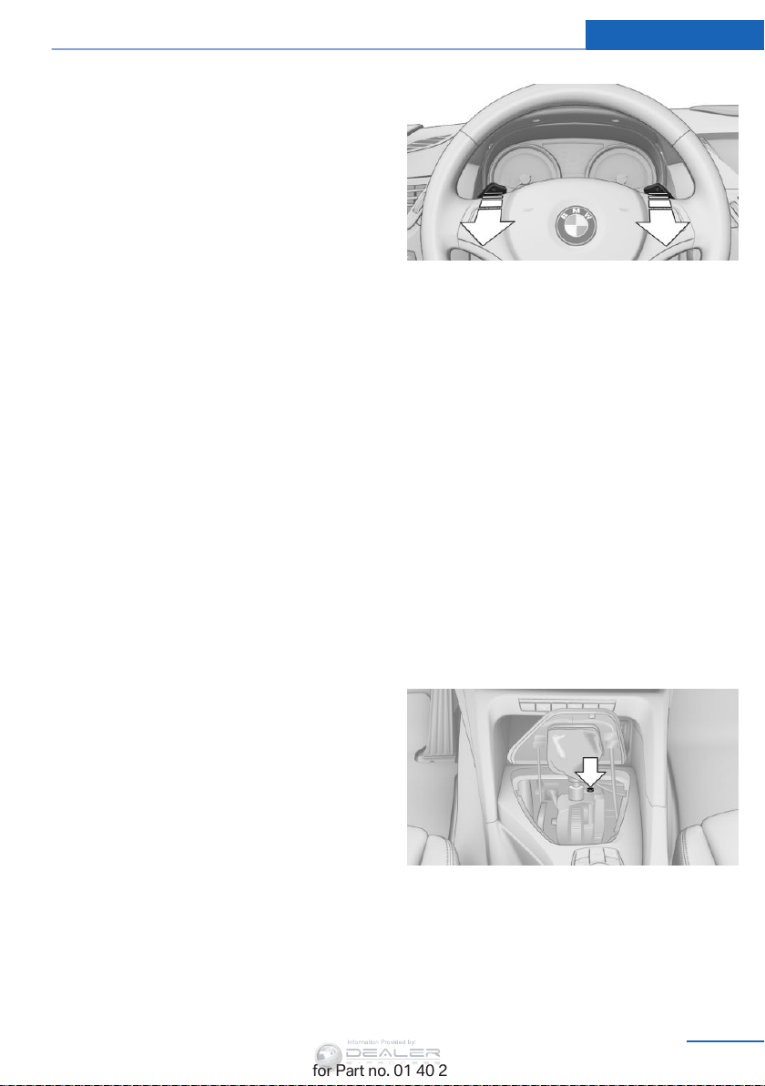
Activating the M/S manual mode
Information Provided by:
Move the selector lever from position D toward
the left.
Push the selector lever forward or backward.
Manual mode becomes active and the gear is
changed.
The engaged gear is displayed in the instru‐
ment cluster, e.g., M1.
▷ To shift down: press the selector lever for‐
ward.
▷ To shift up: press the selector lever back‐
ward.
The vehicle only shifts up or down at appropri‐
ate engine and road speeds, e.g., it does not
shift down if the engine speed is too high. The
selected gear is briefly displayed in the instru‐
ment panel, followed by the current gear.
Shifting gears using the
shift paddles
on the steering wheel
The shift paddles on the steering wheel allow
you to shift gears quickly while keeping both
hands on the steering wheel.
▷ When the shift paddles on the steering
wheel are used to shift gears while in auto‐
matic mode, the transmission switches to
manual mode.
▷ If the shift paddles are not used to acceler‐
ate or shift gears for a certain amount of
time, the transmission switches back to
automatic mode.
If the selector lever is in the M/S gear plane,
manual mode remains active.
Driving Controls
▷ Shift up: briefly pull right shift paddle +.
▷ Shift down: briefly pull left shift paddle –.
The vehicle only shifts up or down at appropri‐
ate engine and road speeds, e.g., it does not
shift down if the engine speed is too high. The
selected gear is briefly displayed in the instru‐
ment panel, followed by the current gear.
Overriding selector lever lock
If the selector lever is locked in position P al‐
though the ignition is switched on, the brake is
depressed, and the button on the selector
lever is pressed, the selector lever lock can be
overridden:
1. Switch off the ignition.
2. Unclip the sleeve of the selector lever.
3. Pull the sleeve up over the selector lever
until the sleeve is inside out.
4. Using the screwdriver from the tool kit, re‐
fer to page 249, press the red lever while
moving the selector lever to the desired
position with the button pressed.
Online Edition for Part no. 01 40 2 954 052 - II/15
69
Page 72
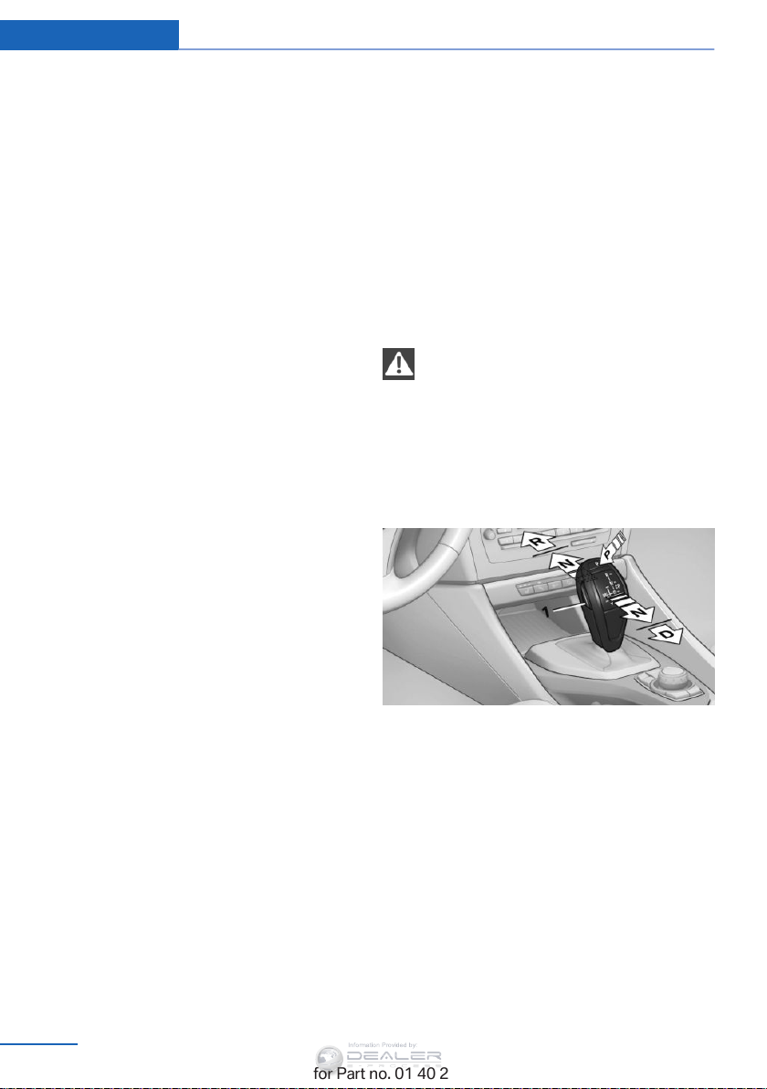
Controls Driving
Information Provided by:
Automatic transmission with Steptronic, 8-gear
Transmission positions
D Drive, automatic position
Position for normal vehicle operation. All for‐
ward gears are available.
Under normal operating conditions, fuel con‐
sumption is lowest when you are driving in po‐
sition D.
Kickdown
Kickdown is used to achieve maximum driving
performance. Press on the accelerator beyond
the resistance point at the full throttle position.
R is Reverse
Select only when the vehicle is stationary.
N is Neutral
The vehicle can roll.
N remains engaged after the engine is
switched off if the remote control remains in
the ignition lock. This function can be used in
an automatic car wash, refer to page 263, for
example. P is automatically engaged after ap‐
prox. 30 minutes.
Before leaving the vehicle, ensure that the
transmission position P is engaged; otherwise,
the vehicle may begin to roll.
Engaging transmission position
▷ Transmission position P can only be disen‐
gaged if the engine is running and the
brake pedal is pressed.
▷ With the vehicle stationary, press on the
brake pedal before shifting out of P or N;
otherwise, the shift command will not be
executed: shift lock.
Press on the brake pedal until you start
driving
To prevent the vehicle from creeping after you
select a driving position, maintain pressure on
the brake pedal until you are ready to start.
◀
Engaging transmission positions D, R,
N
P Park
The drive wheels are blocked.
P is engaged automatically when the following
conditions are met:
▷ The driver's door is opened while the en‐
gine is running, the safety belt is not fas‐
tened and neither the brake pedal nor the
accelerator is activated.
▷ The engine is switched off unless N is en‐
gaged and the remote control is in the igni‐
tion lock.
▷ The remote control is removed from the ig‐
nition lock.
70
Online Edition for Part no. 01 40 2 954 052 - II/15
Briefly push the selector lever in the desired di‐
rection, beyond a resistance point if necessary.
When shifting out of P or into R, simultane‐
ously push the unlock button 1.
The engaged transmission position is dis‐
played on the selector lever.
After releasing the selector lever, it returns to
its center position.
Engaging transmission position P
Select only when the vehicle is stationary.
Page 73
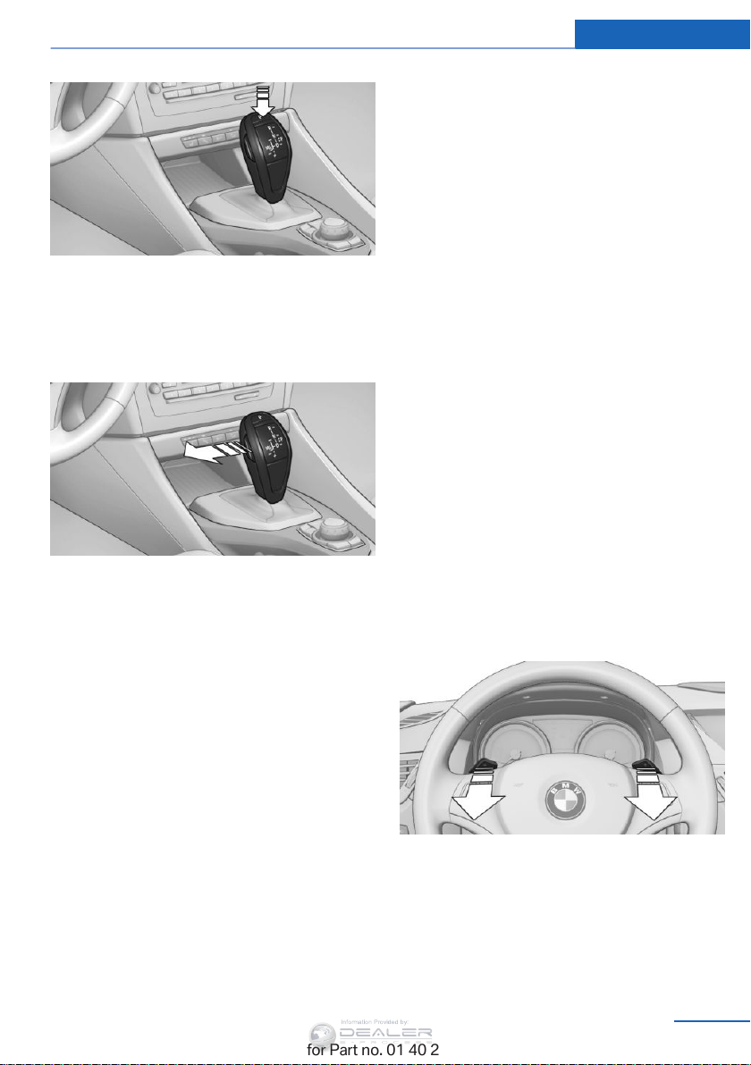
Press button P.
Information Provided by:
Sport program and manual mode M/S
Activating the Sport program
Push the selector lever to the left out of trans‐
mission position D.
The Sport program is activated and DS is dis‐
played in the instrument cluster.
This position is recommended for a perform‐
ance-oriented driving style.
Driving Controls
The transmission only shifts up or down if the
rpm and vehicle speed are appropriate. If the
engine speed is too high, the transmission
does not shift down.
The selected gear is briefly displayed in the in‐
strument panel, followed by the current gear.
Ending the Sport program/manual
mode
Push the selector lever to the right.
D is displayed in the instrument cluster.
Shifting gears using the shift paddles
on the steering wheel
The shifting paddles make it possible to
quickly change gears since both hands can re‐
main on the steering wheel.
▷ If the shift paddles on the steering wheel
are used to shift gears while in automatic
mode D, the transmission temporarily
switches to manual mode.
▷ If the shift paddles are not used to acceler‐
ate or shift gears for a certain amount of
time, the transmission switches back to
automatic mode D.
With the transmission position M/S selected,
the manual mode remains active.
Activating manual mode
Push the selector lever to the left out of trans‐
mission position D.
Push the selector lever forward or backward.
Manual mode becomes active and the gear is
changed.
The engaged gear is displayed in the instru‐
ment cluster, e.g., M1.
▷ To shift down: press the selector lever for‐
ward.
▷ To shift up: press the selector lever back‐
ward.
Online Edition for Part no. 01 40 2 954 052 - II/15
▷ Shift up: pull right shift paddle.
▷ Shift down: pull left shift paddle.
The vehicle only shifts up or down at appropri‐
ate engine and road speeds, e.g., it does not
shift down if the engine speed is too high.
The selected gear is briefly displayed in the in‐
strument cluster, followed by the current gear.
71
Page 74
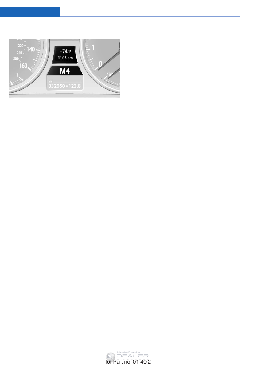
Controls Driving
Information Provided by:
Displays in the instrument cluster
The transmission position is displayed and the
engaged gear, such as M4, is displayed in
manual mode.
72
Online Edition for Part no. 01 40 2 954 052 - II/15
Page 75
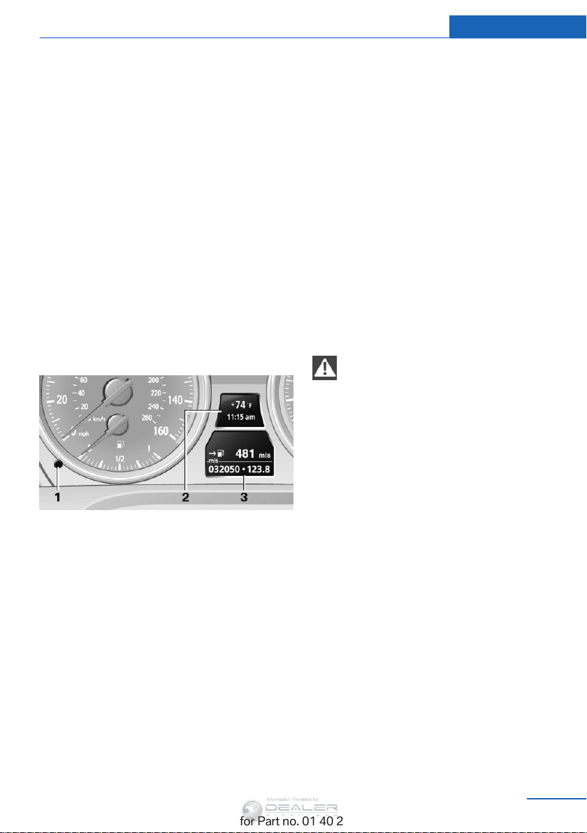
Displays
Information Provided by:
Displays Controls
Vehicle equipment
This chapter describes all series equipment as
well as country-specific and special equipment
offered for this model series. Therefore, it also
describes equipment that may not be found in
your vehicle, for instance due to the selected
special equipment or the country version. This
also applies to safety-related functions and
systems.
When using the features and systems descri‐
bed here, adhere to local regulations.
Odometer, external temperature display, clock
1 Knob in the instrument cluster
2 External temperature display and clock
3 Odometer and trip odometer
Knob in the instrument cluster
Press the knob.
▷ When the ignition is switched on, the trip
odometer is reset.
▷ When the ignition is switched off, the time,
external temperature and odometer are
displayed.
Units of measure
To set the respective units of measure, miles
or km for the odometer and ℃ or ℉ for the ex‐
ternal temperature, refer to page 77.
The setting is stored for the remote control
currently in use.
Time, external temperature display
Set the time, refer to page 77.
External temperature warning
If the display drops to +37 ℉/+3 ℃, a signal
sounds and a warning lamp lights up. There is
the increased danger of ice.
Ice on roads
Even at temperatures above
+37 ℉/+3 ℃, there can be a risk of ice on
roads.
Therefore, drive carefully on bridges and shady
roads, for example, to avoid the increased dan‐
ger of an accident.◀
Odometer and trip odometer
Resetting trip odometer:
With the ignition switched on, press button 1 in
the instrument cluster.
When the vehicle is parked
If you still want to view the time, external tem‐
perature and odometer reading briefly after the
remote control has been taken out of the igni‐
tion lock:
Press button 1 in the instrument cluster.
Online Edition for Part no. 01 40 2 954 052 - II/15
73
Page 76
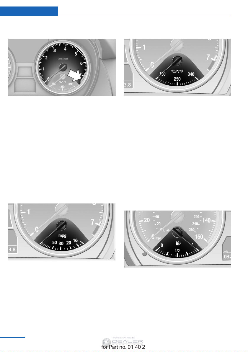
Controls Displays
Information Provided by:
Tachometer
Never force the engine speed up into the red
warning field, see arrow. In this range, the fuel
supply is interrupted to protect the engine.
Coolant temperature
A warning lamp will come on if the coolant, and
therefore the engine, becomes too hot. In addi‐
tion, a message will appear on the Control Dis‐
play.
Check the coolant level, refer to page 246.
Current fuel consumption
Engine oil temperature
▷ Cold engine: the pointer is at the low tem‐
perature end. Drive at moderate engine
and vehicle speeds.
▷ Normal operating temperature: the pointer
is in the middle or in the right half of the
temperature display.
▷ Hot engine: the pointer is at the high tem‐
perature end. Switch off the engine imme‐
diately and allow it to cool down.
If the engine oil temperature is too high, a mes‐
sage appears on the Control Display.
Check the oil level, refer to page 243.
Fuel gauge
Displays the current fuel consumption. You
can check whether you are currently driving in
an efficient and environmentally-friendly man‐
ner.
74
Online Edition for Part no. 01 40 2 954 052 - II/15
The vehicle inclination may cause the display
to vary.
The arrow on the fuel pump symbol indicates
the side of the vehicle with the fuel filler flap.
Notes on refueling, refer to page 228.
Range
After the reserve range is reached:
Page 77
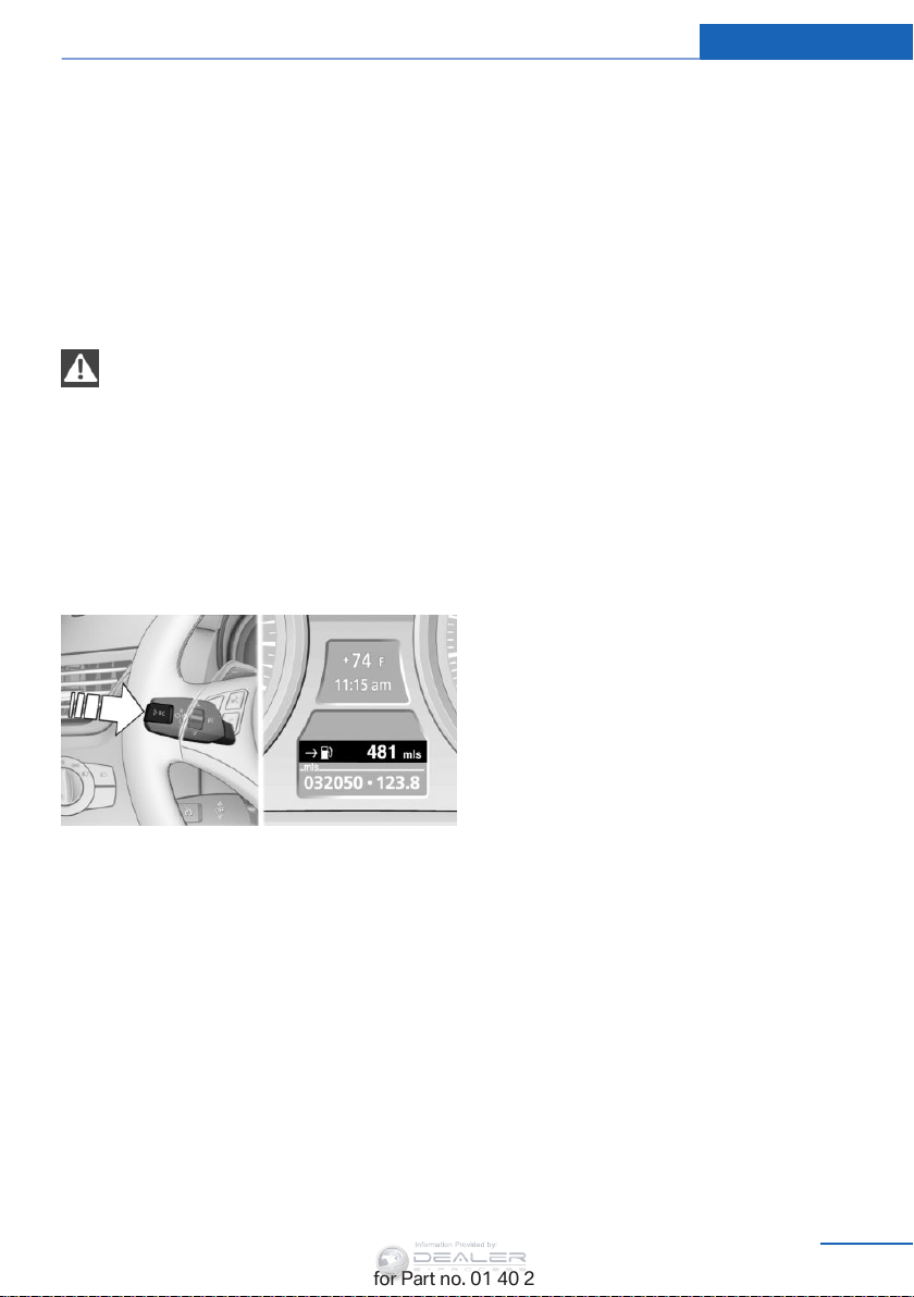
Displays Controls
Information Provided by:
▷ A message is briefly displayed on the Con‐
trol Display.
▷ The remaining range is shown on the com‐
puter.
▷ When a dynamic driving style is used, such
as when corners are taken rapidly, engine
functions are not ensured.
The message appears continuously below a
range of approx. 30 miles/50 km.
Refuel promptly
At the latest, refuel at a range below
30 miles/50 km; otherwise, the engine function
is not ensured and damage may occur.
◀
Computer
Displaying information on the
instrument panel
Press the computer button on the turn signal
lever.
Information is displayed in the instrument clus‐
ter.
Overview of the information
Repeatedly pressing the button on the turn
signal lever displays the information on the in‐
strument cluster in the following order:
▷ Range.
▷ ECO PRO bonus range.
▷ Average speed.
▷ Average fuel consumption.
▷ Current fuel consumption.
▷ No information.
To set the corresponding units of measure, re‐
fer to page 77.
Information in detail
Range
Displays the estimated cruising range available
with the remaining fuel.
It is calculated based on your driving style over
the last 18 miles/30 km.
Average speed
Periods in which the vehicle was parked and
the engine was switched off manually are not
included in the average speed calculations.
With the trip computer, refer to page 76, you
can have the average speed displayed for an
additional distance.
To reset the average speed: press the button
on the turn indicator lever for approx. 2 sec‐
onds.
Average fuel consumption
This is calculated for the period during which
the engine is running.
The average consumption is computed based
on the distance traveled since the last time the
computer was reset.
You can have the average consumption for an‐
other trip displayed, refer to Displays on the
Control Display below.
To reset the average consumption: press the
button on the turn indicator lever for ap‐
prox. 2 seconds.
Current fuel consumption
Displays the current fuel consumption. You
can check whether you are currently driving in
an efficient and environmentally-friendly man‐
ner.
Online Edition for Part no. 01 40 2 954 052 - II/15
75
Page 78
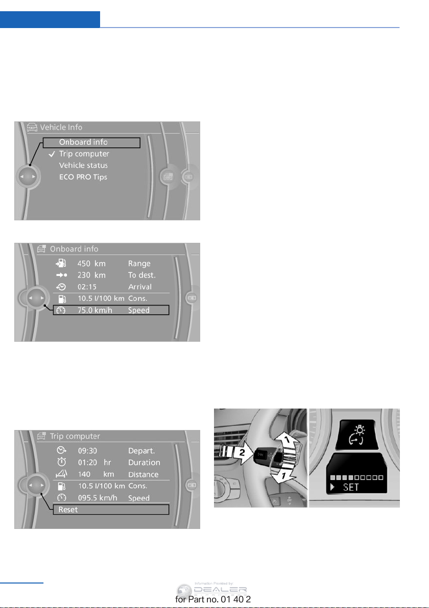
Controls Displays
Information Provided by:
Displays on the Control Display
Display the computer or trip computer on the
Control Display.
1. "Vehicle Info"
2. "Onboard info" or "Trip computer"
Displays on the "Onboard info":
▷ Trip distance.
Both displays show:
▷ Average fuel consumption and
▷ Average speed.
Resetting the fuel consumption and
speed
Resetting the values for average speed and
average fuel consumption:
1. Select the respective menu item and press
the controller.
2. Press the controller again to confirm your
selection.
Resetting the trip computer
Resetting all values:
1. "Vehicle Info"
2. "Trip computer"
3. "Reset"
Settings and information
▷ Range.
▷ Distance to destination.
▷ Estimated time of arrival if a destination
was entered in the navigation system, refer
to page 146.
Displays on the "Trip computer":
▷ Departure time.
▷ Trip duration.
76
Online Edition for Part no. 01 40 2 954 052 - II/15
Operating concept
Certain settings and information can only be
called up when the ignition is switched on. A
number of settings cannot be made while driv‐
ing.
1 Button for:
▷ Selecting the display.
▷ Setting values.
2 Button for:
Page 79
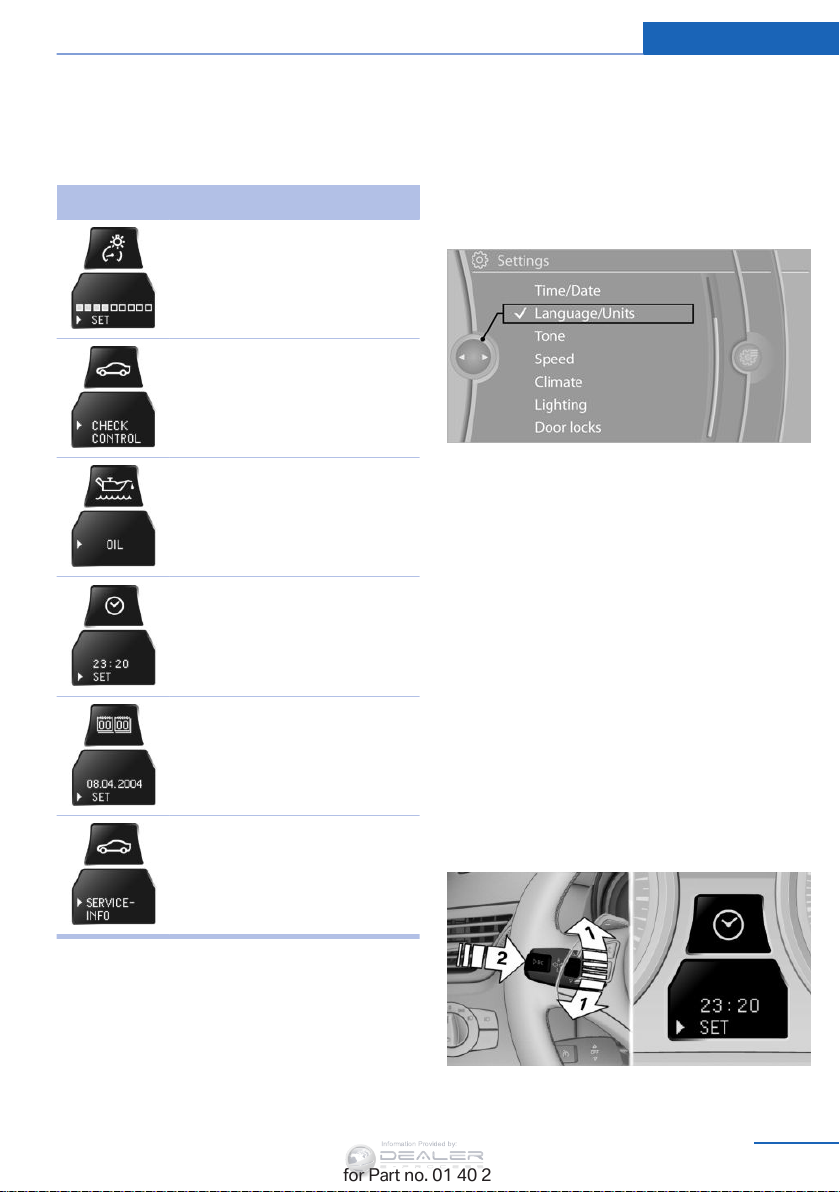
Displays Controls
Information Provided by:
▷ Confirming the selected display or set
values.
▷ Calling up computer information 75.
Symbol Function
With the lights switched on:
Dimming instrument lighting,
refer to page 89
Calling up Check Control, refer
to page 82
Checking the engine oil level,
refer to page 243
Setting the time, refer to
page 77
Units of measure
The units for fuel consumption, route/distance,
temperature, and pressure can be changed.
1. "Settings"
2. "Language/Units"
3. Select the desired menu item.
4. Select the desired unit.
The settings are stored for the remote control
currently in use.
Clock
Setting the time
Setting the date, refer to
page 78
Viewing service requirement
display, refer to page 80
Exiting displays
The external temperature reading and the time
reappear when you press button 2 or if you
make no entries within approx. 15 seconds. If
required, complete the current setting first.
Online Edition for Part no. 01 40 2 954 052 - II/15
In the instrument cluster
To set the 12h/24h format, refer to Setting the
time format below.
1. Press button 1 in the turn indicator lever up
or down repeatedly until the appropriate
symbol appears in the display, accompa‐
nied by the time and the word "SET".
2. Press button 2.
77
Page 80
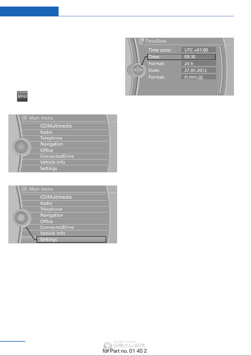
Controls Displays
Information Provided by:
3. Use button 1 to set the hours.
4. Press button 2 to confirm the entry.
5. Use button 1 to set the minutes.
6. Press button 2 to confirm the entry.
7. Press button 2.
The system accepts the new time.
Via the iDrive
1. Press the button.
The main menu is displayed.
2. "Settings"
3. "Time:"
4. Turn the controller until the desired hours
are displayed, and then press the control‐
ler.
5. Turn the controller until the desired mi‐
nutes are displayed, and then press the
controller.
The time is stored.
Setting the time format
1. "Settings"
2. "Time/Date"
3. "Format:"
4. Select the desired format.
The time format is stored.
The settings are stored for the remote control
currently in use.
Setting the time zone
1. "Settings"
2. "Time/Date"
3. "Time zone:"
4. Select the desired time zone.
The time zone is stored.
Setting the time
1. "Settings"
2. "Time/Date"
78
Online Edition for Part no. 01 40 2 954 052 - II/15
Date
The settings are stored for the remote control
currently in use, Personal Profile, refer to
page 32.
Setting the date
In the instrument cluster
To set the dd/mm or mm/dd date format, refer
to Setting the date format below.
1. Press button 1 in the turn indicator lever up
or down repeatedly until the appropriate
Page 81
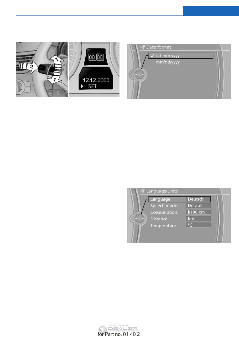
Displays Controls
Information Provided by:
symbol appears in the display, accompa‐
nied by the date and the word "SET".
2. Press button 2.
3. Use button 1 to set the day of the month.
4. Press button 2 to confirm the entry.
5. Set the month and the year in the same
way.
6. Press button 2.
The system stores the new date.
Via the iDrive
1. "Settings"
2. "Time/Date"
3. "Date:"
4. Turn the controller until the desired day is
displayed, and then press the controller.
5. Make the necessary settings for the month
and year.
The date is stored.
3. "Format:"
4. Select the desired format.
The date format is stored.
Settings on the Control Display
Language
Setting the language
1. "Settings"
2. "Language/Units"
3. "Language:"
Setting the date format
1. "Settings"
2. "Time/Date"
Online Edition for Part no. 01 40 2 954 052 - II/15
4. Select the desired language.
The setting is stored for the remote control
currently in use.
Setting the voice dialog
Voice dialog for the voice activation system,
refer to page 28.
79
Page 82
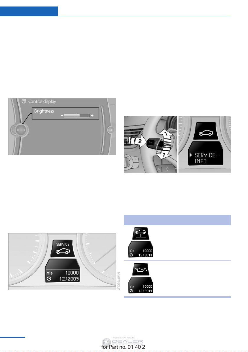
Controls Displays
Information Provided by:
Brightness
Setting the brightness
The brightness is automatically adapted to the
ambient lighting conditions. However, the ba‐
sic setting can be adjusted.
1. "Settings"
2. "Control display"
3. "Brightness"
4. Turn the controller until the desired setting
is selected.
5. Press the controller.
The setting is stored for the remote control
currently in use.
Depending on the light conditions, the bright‐
ness control may not be clearly visible.
The current service requirements can be read
out from the remote control by the service
specialist.
For certain maintenance operations, you can
view the distance remaining or the due date for
that operation in the instrument cluster.
1. Switch on the ignition, refer to page 60.
2. Lightly press button 1 in the turn indicator
lever up or down repeatedly until the ap‐
propriate symbol appears in the display,
accompanied by the words "SERVICE
INFO".
3. Press button 2.
4. Use button 1 to scroll through the individ‐
ual service items.
Displays
Service requirements
The remaining driving distance and the date of
the next scheduled service are displayed
briefly immediately after you start the engine
or switch on the ignition.
80
Online Edition for Part no. 01 40 2 954 052 - II/15
Symbol Function
Service requirements
Engine oil
Page 83
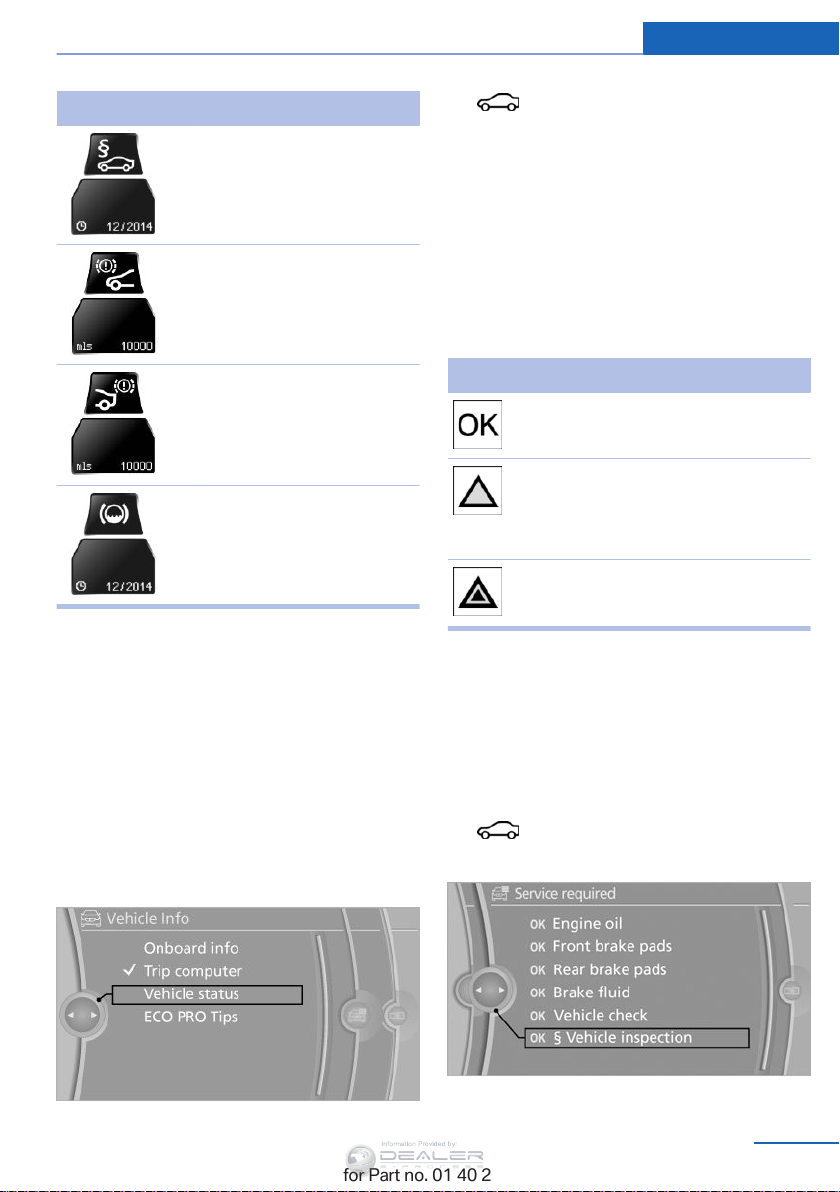
Displays Controls
Information Provided by:
Symbol Function
Roadworthiness test
Front brake pads
Rear brake pads
Brake fluid
The sequence of displayed service items may
vary. First the data for the next maintenance
are displayed.
Detailed information on service
requirements
More information on the scope of service re‐
quired can be displayed on the Control Dis‐
play.
1. "Vehicle Info"
2. "Vehicle status"
3. "Service required"
Required maintenance procedures and legally
mandated inspections are displayed.
Additional information can be displayed on
each entry:
Select the entry and press the controller.
To exit from the menu:
Move the controller to the left.
Symbols
Symbols Description
No service is currently re‐
quired.
The deadline for scheduled
maintenance or a legally man‐
dated inspection is approach‐
ing.
The service deadline has al‐
ready passed.
Entering dates
Enter the dates for the required inspections.
Make sure the date on the Control Display is
set correctly, refer to page 78.
1. "Vehicle Info"
2. "Vehicle status"
3.
4. "§ Vehicle inspection"
"Service required"
5. Open the menu for entering the deadline.
Online Edition for Part no. 01 40 2 954 052 - II/15
81
Page 84
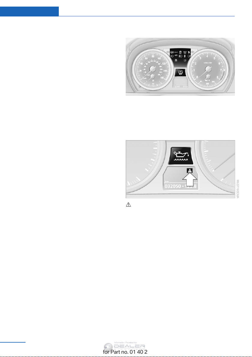
Controls Displays
Information Provided by:
6. "Date:"
7. Create the settings.
8. Press the controller to apply the setting.
The year is highlighted.
9. Turn the controller to make the adjust‐
ment.
10. Press the controller to apply the setting.
The date entry is stored.
To exit from the menu:
Move the controller to the left.
Automatic Service Request
Data regarding the maintenance status or le‐
gally mandated inspections of the vehicle are
automatically transmitted to your service cen‐
ter before a service due date.
You can check when your service center was
notified.
1. "Vehicle Info"
2. "Vehicle status"
3. Open "Options".
4. "Last Service Request"
Indicator/warning lamps
The indicator and warning lamps can light up in
a variety of combinations and colors.
Several of the lamps are checked for proper
functioning and light up temporarily when the
engine is started or the ignition is switched on.
Check Control
The concept
The Check Control monitors vehicle functions
and alerts you to any malfunctions in the sys‐
tems monitored.
A Check Control message consists of indicator
and warning lamps in the instrument cluster
and, in some circumstances, an acoustic signal
and text messages at the top of the Control
Display.
82
Online Edition for Part no. 01 40 2 954 052 - II/15
The symbol indicates that Check Control
messages have been stored. The Check Con‐
trol messages can be displayed later.
Text messages
Text messages at the upper edge of the Con‐
trol Display in combination with a symbol in the
instrument cluster explain a Check Control
message and the meaning of the indicator and
warning lamps.
Supplementary text messages
Additional information, such as on the cause of
a fault or the required action, can be called up
via Check Control.
In urgent cases, this information will be shown
as soon as the corresponding lamp comes on.
Page 85
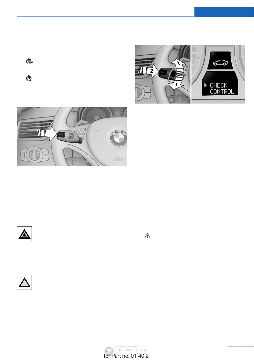
Displays Controls
Information Provided by:
Symbols
The following functions can be selected within
the supplementary text message, depending
on the Check Control message.
▷ "Service request"
Contact the service partner.
▷ "Roadside Assistance"
Contact Roadside Assistance.
Hiding Check Control messages
Press the computer button in the turn signal
lever.
Some Check Control messages are displayed
until the malfunctions have been rectified.
They cannot be hidden.
If several malfunctions occur at once, the mes‐
sages are displayed consecutively.
They are marked with the symbol
shown here.
Other Check Control messages are hidden au‐
tomatically after approx. 20 seconds. However,
they are stored and can be displayed again
later.
They are marked with the symbol
shown here.
accompanied by the words "CHECK CON‐
TROL".
2. Press button 2.
If there is no Check Control message, this
is indicated by "CHECK OK“. If a Check
Control message has been stored, the cor‐
responding lamp comes on. It is accompa‐
nied by a text message on the Control Dis‐
play.
3. Press button 1 to check for other mes‐
sages.
4. Press button 2.
The display again shows the external tem‐
perature and the time.
Displaying stored Check Control
messages
1. "Vehicle Info"
2. "Vehicle status"
3. "Check Control"
4. Select the text message.
Messages after trip completion
Special messages that were displayed during a
trip are displayed again after the ignition is
switched off.
Viewing stored Check Control
messages
1. Lightly press button 1 in the turn indicator
lever up or down repeatedly until the ap‐
propriate symbol appears in the display,
Online Edition for Part no. 01 40 2 954 052 - II/15
Speed limit
Entry of a speed limit which, when reached,
should cause a Check Control message to be
issued.
83
Page 86
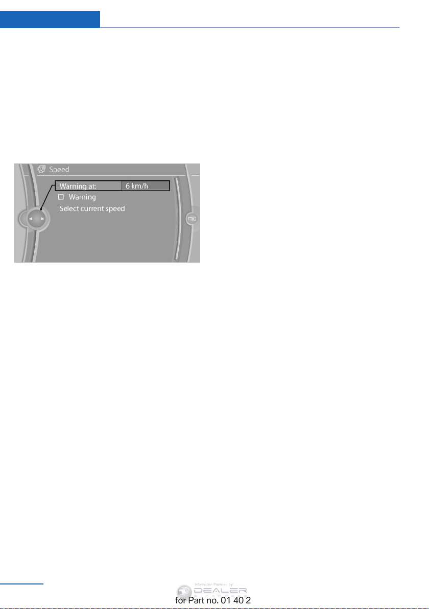
Controls Displays
Information Provided by:
Renewed warning if the vehicle speed drops
below the set speed limit once by at least
3 mph/5 km/h.
Displaying, setting or changing the
limit
1. "Settings"
2. "Speed"
3. "Warning at:"
4. Turn the controller until the desired limit is
displayed.
5. Press the controller.
The speed limit is stored.
Applying your current speed as the
limit
1. "Settings"
2. "Speed"
3. "Select current speed"
The system adopts your current speed as the
limit.
Activating/deactivating the limit
1. "Settings"
2. "Speed"
3. "Warning"
84
Online Edition for Part no. 01 40 2 954 052 - II/15
Page 87
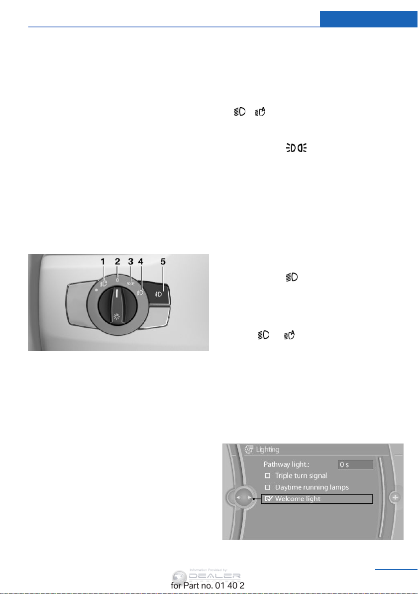
Lamps
Information Provided by:
Lamps Controls
Vehicle equipment
This chapter describes all series equipment as
well as country-specific and special equipment
offered for this model series. Therefore, it also
describes equipment that may not be found in
your vehicle, for instance due to the selected
special equipment or the country version. This
also applies to safety-related functions and
systems.
When using the features and systems descri‐
bed here, adhere to local regulations.
At a glance
1 Automatic headlamp control / Adaptive
Light Control / High-beam Assistant / wel‐
come lamps / daytime running lights
2 Lamps off / daytime running lights
3 Parking lamps / daytime running lights
4 Low beams/welcome lamps
5 Fog lights
off automatically in the following switch set‐
tings:
0, ,
Parking lamps
Switch position
up on all sides, e.g., for parking.
Do not use the parking lamps for extended pe‐
riods; otherwise, the battery may become dis‐
charged and it would then be impossible to
start the engine.
When parking, it is preferable to switch on the
one-sided roadside parking lamps, refer to
page 87.
: the vehicle lamps light
Low beams
Switch position with the ignition switched
on: the low beams light up.
Welcome lights
When parking the vehicle, leave the switch in
position or : the parking and interior
lamps light up briefly when the vehicle is un‐
locked.
Activating/deactivating the welcome
lamps
1. "Settings"
2. "Lighting"
3. "Welcome light"
Parking lights/low beams, headlight control
General information
If the driver's door is opened while the ignition
is switched off, the exterior lighting is switched
Online Edition for Part no. 01 40 2 954 052 - II/15
85
Page 88
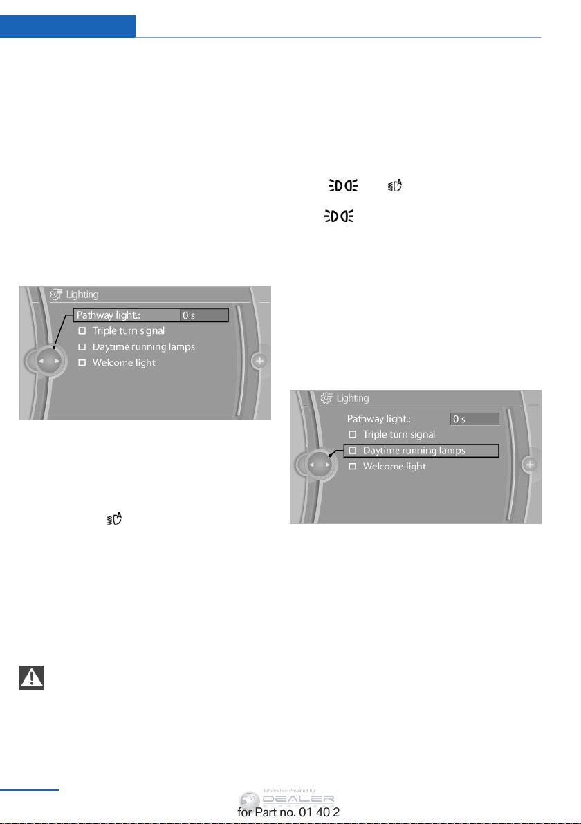
Controls Lamps
Information Provided by:
The setting is stored for the remote control
currently in use.
Headlight courtesy delay feature
The low beams stay lit for a short while after
the ignition is switched off, if the lights are
switched off and the headlight flasher is
switched on.
Setting the duration
1. "Settings"
2. "Lighting"
3. "Pathway light.: s"
4. Set the duration.
The setting is stored for the remote control
currently in use.
For example, the sensors are unable to detect
fog or hazy weather. To avoid safety risks, you
should always switch on the lamps manually
under these conditions.◀
Daytime running lights
The daytime running lights light up in posi‐
tion 0, and . After the ignition is
switched off, the parking lamps light up in po‐
sition .
Activating/deactivating
In some countries, driving with daytime run‐
ning lights is mandatory; for this reason, day‐
time running lights cannot be deactivated in
these cases.
1. "Settings"
2. "Lighting"
3. "Daytime running lamps"
Automatic headlamp control
Switch position : the low beams are
switched on and off automatically, e.g., in tun‐
nels, in twilight or if there is precipitation. The
LED next to the symbol lights up.
A blue sky with the sun low on the horizon can
cause the lights to be switched on.
The low beams remain switched on independ‐
ent of the ambient lighting conditions when
you switch on the front fog lamps.
Personal responsibility
The automatic headlamp control cannot
serve as a substitute for your personal judg‐
ment in determining when the lamps should be
switched on in response to ambient lighting
conditions.
86
Online Edition for Part no. 01 40 2 954 052 - II/15
The setting is stored for the remote control
currently in use.
Adaptive Light Control
The concept
Adaptive Light Control is a variable headlamp
control system that enables dynamic illumina‐
tion of the road surface.
Depending on the steering angle and other pa‐
rameters, the light from the headlamp follows
the course of the road.
In sharp curves, e.g. serpentines, or during
turning, up to a certain speed one of the two
Page 89
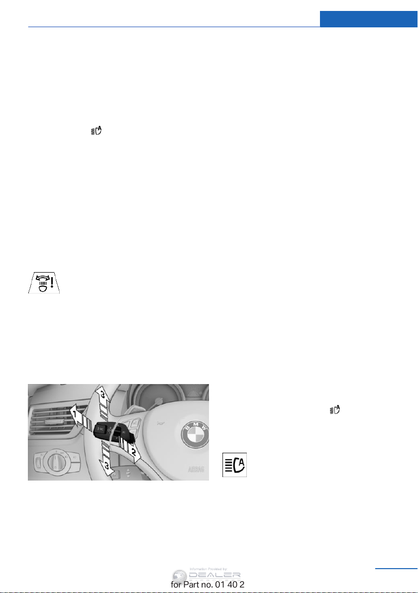
Lamps Controls
Information Provided by:
front fog lamps is switched on as a turning
lamp. This provides improved illumination of
the area inside the curve.
Controls
Activating
Switch position with the ignition switched
on.
The turning lamps are automatically switched
on depending on the steering angle or the use
of turn signals.
To avoid blinding oncoming traffic, the Adap‐
tive Light Control does not swivel to the driv‐
er's side when the vehicle is at a standstill.
When driving in reverse, both turning lamps
are active.
Malfunction
The warning lamp lights up.A mes‐
sage appears on the Control Display.
Adaptive Light Control is malfunc‐
tioning or has failed. Have the system checked
as soon as possible.
High-beams/roadside parking lights
Left and right roadside parking lamps
The vehicle can be illuminated on one side.
Switching on
After parking the vehicle, press the lever up or
down beyond the resistance point for ap‐
prox. 2 seconds, arrow 3.
The roadside parking lights drain the battery.
Therefore, do not leave them on for unduly
long periods of time; otherwise, the battery
might not have enough power to start the en‐
gine.
Switching off
Briefly press the lever in the opposite direction
to the pressure point, arrow 3.
High-beam Assistant
The concept
When the lights are switched on, this system
automatically switches the high beams on and
off. The procedure is controlled by a sensor on
the front of the interior rearview mirror. The as‐
sistant ensures that the high beams are
switched on whenever the traffic situation al‐
lows. The driver can intervene at any time and
switch the high beams on and off as usual.
1 High-beams
2 Headlamp flasher
3 Roadside parking lamps
Online Edition for Part no. 01 40 2 954 052 - II/15
Activating the High-beam Assistant
1. Turn the light switch to .
2. With the low beams switched on, briefly
push the turn indicator lever in the direc‐
tion of the high beam.
The indicator lamp in the instrument
cluster lights up. The high beams are
switched on and off automatically.
The system responds to light from oncoming
traffic and traffic driving ahead of you, and to
adequate illumination, e.g., in towns and cities.
87
Page 90
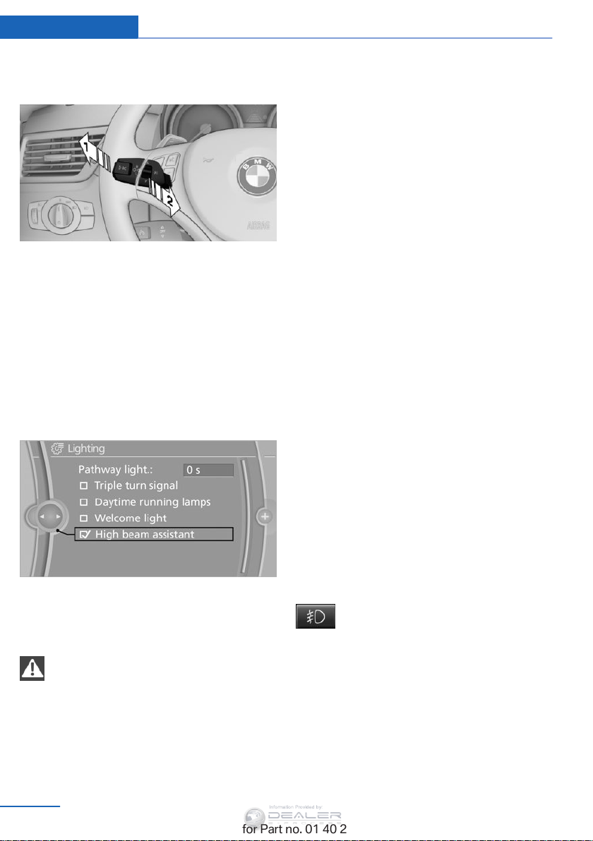
Controls Lamps
Information Provided by:
Switching the high beams on and off
manually
▷ High beams on, arrow 1.
▷ High beams off/headlamp flasher, arrow 2.
To reactivate the High-beam Assistant, briefly
push the turn indicator lever toward the high
beams.
Activating/deactivating via iDrive
1. "Settings"
2. "Lighting"
3. "High beam assistant"
The system is not fully functional in situations
such as the following, and driver intervention
may be necessary:
▷ In very unfavorable weather conditions,
such as fog or heavy precipitation.
▷ In detecting poorly-lit road users, such as
pedestrians, cyclists, horseback riders and
wagons; when driving close to train or ship
traffic; and at animal crossings.
▷ In tight curves, on hilltops or in depres‐
sions, in cross traffic or half-obscured on‐
coming traffic on freeways.
▷ In poorly-lit towns and cities and in the
presence of highly reflective signs.
▷ At low speeds.
▷ When the windshield in front of the interior
rearview mirror is fogged over, dirty or cov‐
ered with stickers, etc.
▷ If the sensor view field is dirty.
The view field of the sensor is located on
the front of the interior rearview mirror.
Do not cover this area with stickers, etc.
Clean the sensor view field with a cloth
moistened with a small amount of glass
cleaner.
The setting is stored for the remote control
currently in use.
System limits
Personal responsibility
The High-beam Assistant cannot serve
as a substitute for the driver's personal judg‐
ment of when to use the high beams. There‐
fore, manually switch off the high beams in sit‐
uations where this is required to avoid a safety
risk.◀
88
Online Edition for Part no. 01 40 2 954 052 - II/15
Fog lights
Front fog lamps
The low beams must be switched on.
Press the button. The green indicator
lamp in the instrument cluster lights
up.
If the automatic headlamp control, refer to
page 86, is activated, the low beams will come
on automatically when you switch on the fog
lamps.
Page 91
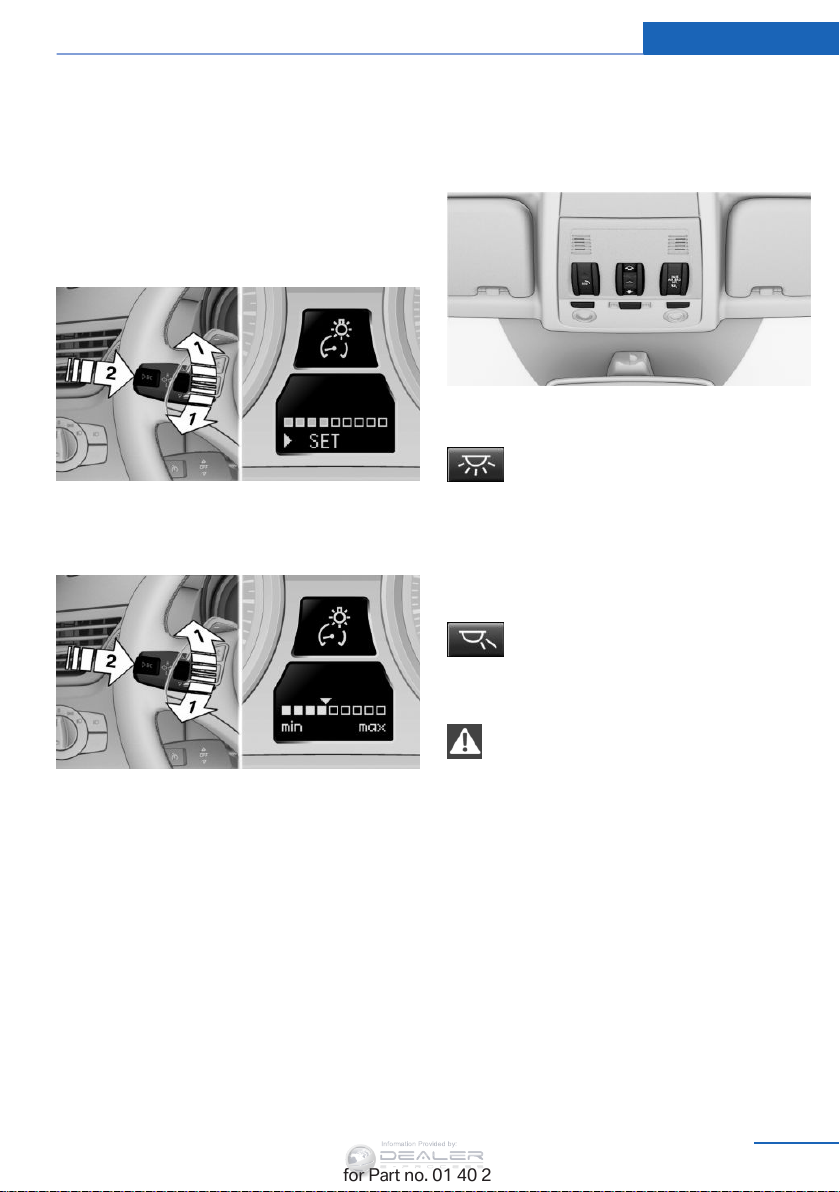
Lamps Controls
Information Provided by:
Instrument lighting
The parking lamps or low beams must be
switched on to adjust the brightness.
1. Push button 1 up or down repeatedly until
the appropriate symbol appears in the dis‐
play, accompanied by the brightness set‐
ting and the word "SET".
2. Press button 2.
3. Push button 1 up or down to select the de‐
sired brightness level.
4. Press button 2.
The display again shows the external tem‐
perature and the time.
Interior lights
General information
The interior lights, footwell lights, cargo area
lights, and courtesy lights are controlled auto‐
matically.
The LEDs for the courtesy lights are set in the
door handles and illuminate the ground in front
of the doors.
To avoid draining the battery, all lights inside
the car are switched off about 8 minutes after
the ignition is switched off, Start/Stop button,
refer to page 59.
Switching the interior lights on and off
Press the button.
To switch off permanently: press the button for
approx. 3 seconds.
To clear this setting: briefly press the button.
Reading lights
Press the button.
Reading lights are located at the front and rear
next to the interior lights.
Danger of burns
Do not reach into the opening of the
lamps; otherwise, there is a risk of burns.
◀
Ambient lighting
Depending on the equipment, the interior light‐
ing can be set individually for some lights.
Selecting the color scheme
1. "Settings"
2. "Lighting"
3. "Ambient:"
4. Select the desired setting.
Online Edition for Part no. 01 40 2 954 052 - II/15
89
Page 92
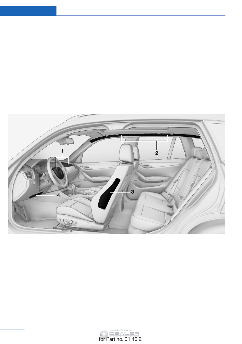
Controls Safety
Information Provided by:
Safety
Vehicle equipment
This chapter describes all series equipment as
well as country-specific and special equipment
offered for this model series. Therefore, it also
describes equipment that may not be found in
your vehicle, for instance due to the selected
Airbags
special equipment or the country version. This
also applies to safety-related functions and
systems.
When using the features and systems descri‐
bed here, adhere to local regulations.
1 Front airbags
2 Head airbags
Front airbags
Front airbags help protect the driver and front
passenger by responding to frontal impacts in
which safety belts alone cannot provide ade‐
quate restraint.
Side airbags
In a lateral impact, the side airbag supports the
side of the body in the chest and lap area.
90
Online Edition for Part no. 01 40 2 954 052 - II/15
3 Side airbags
4 Knee airbag
Head airbags
In a lateral impact, the head airbag supports
the head.
Knee airbag
The knee airbag supports the legs in a frontal
impact.
Page 93

Safety Controls
Information Provided by:
Protective action
Airbags are not triggered in every impact situa‐
tion, e.g., in less severe accidents or rear-end
collisions.
Information on how to ensure the optimal
protective effect of the airbags
▷ Keep at a distance from the airbags.
▷ Always grasp the steering wheel on the
steering wheel rim, holding your hands at
the 3 o'clock and 9 o'clock positions, to
keep the danger of injury to your hands or
arms as low as possible if the airbag is trig‐
gered.
▷ There should be no people, animals, or ob‐
jects between an airbag and a person.
▷ Do not use the cover of the front airbag on
the front passenger side as a storage area.
▷ Keep the dashboard and window on the
front passenger side clear, i.e., do not
cover with adhesive labels or coverings,
and do not attach holders or cables such
as for navigation instruments and mobile
phones.
▷ Make sure that the front passenger is sit‐
ting correctly, i.e., keeps his or her feet and
legs in the footwell; otherwise, leg injuries
can occur if the front airbag is triggered.
▷ Do not place slip covers, seat cushions or
other objects on the front passenger seat
that are not approved specifically for seats
with integrated side airbags.
▷ Do not hang pieces of clothing, such as
jackets, over the backrests.
▷ Make sure that occupants keep their heads
away from the side airbag and do not rest
against the head airbag; otherwise, injuries
can occur if the airbags are triggered.
▷ Do not remove the airbag restraint system.
▷ Do not remove the steering wheel.
▷ Do not apply adhesive materials to the air‐
bag cover panels, cover them or modify
them in any way.
▷ Never modify either the individual compo‐
nents or the wiring in the airbag system.
This also applies to steering wheel covers,
the dashboard, the seats, the roof pillars
and the sides of the headliner.
◀
Even when all instructions are followed closely,
injury from contact with the airbags cannot be
ruled out in certain situations.
The ignition and inflation noise may lead to
short-term and, in most cases, temporary
hearing impairment in sensitive individuals.
In the case of a malfunction, deactivation
and after triggering of the airbags
Do not touch the individual components imme‐
diately after the system has been triggered;
otherwise, there is the danger of burns.
Only have the airbags checked, repaired or dis‐
mantled and the airbag generator scrapped by
your service center or a workshop that has the
necessary authorization for handling explo‐
sives.
Non-professional attempts to service the sys‐
tem could lead to failure in an emergency or
undesired triggering of the airbag, either of
which could result in injury.◀
Warnings and information on the airbags are
also found on the sun visors.
Automatic deactivation of the front
passenger airbags
The system determines whether the front pas‐
senger seat is occupied by measuring the re‐
sistance of the human body.
The front and side airbags on the front passen‐
ger side are activated or deactivated accord‐
ingly by the system.
The indicator lamp above the interior rearview
mirror shows the current status of the front
passenger airbags, deactivated or activated,
refer to Front passenger airbag indicator lamp
below.
Online Edition for Part no. 01 40 2 954 052 - II/15
91
Page 94
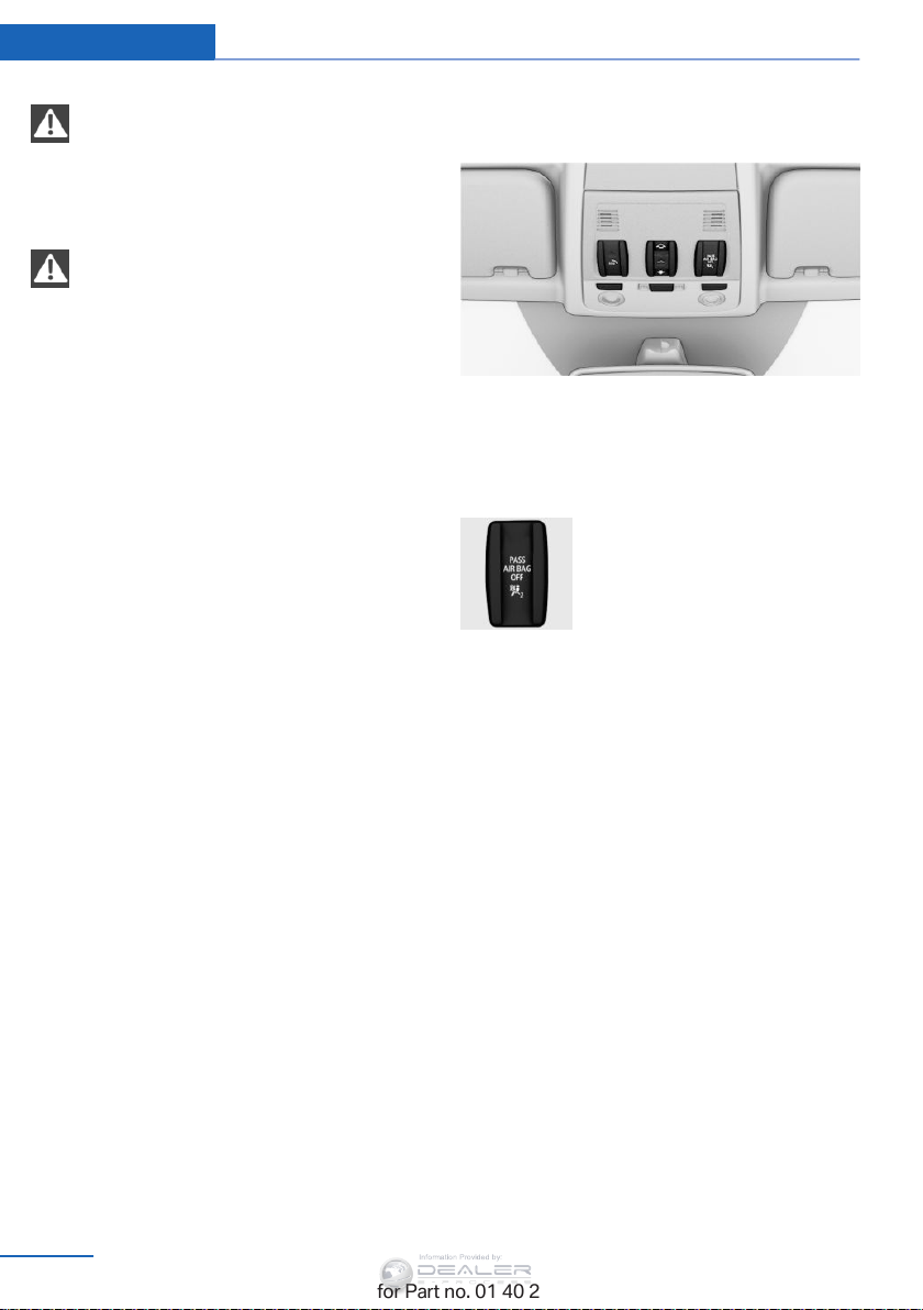
Controls Safety
Information Provided by:
Leave feet in the footwell
Make sure that the front passenger
keeps his or her feet in the footwell; otherwise,
the front passenger airbags may not function
properly.◀
Child restraint fixing system in the front
passenger seat
Before transporting a child on the front pas‐
senger seat, refer to the safety notes and in‐
structions under Children on the front passen‐
ger seat, refer to page 54.◀
Malfunction of the automatic
deactivation system
When transporting older children and adults,
the front passenger airbags may be deacti‐
vated in certain sitting positions. In this case,
the indicator lamp for the front passenger air‐
bags lights up.
In this case, change the sitting position so that
the front passenger airbags are activated and
the indicator lamp goes out.
If it is not possible to activate the airbags, have
the person sit in the rear.
To make sure that occupation of the seat
cushion can be detected correctly:
▷ Do not attach seat covers, seat cushion
padding, ball mats or other items to the
passenger seat unless they are specifically
recommended by BMW.
▷ Do not place electronic devices on the pas‐
senger seat if a child restraint fixing system
is mounted on the seat.
▷ Do not place objects under the seat that
could press against the seat from below.
Indicator lamp for the front passenger
airbags
The indicator lamp for the front passenger air‐
bags indicates the operating state of the front
passenger airbags.
The lamp indicates whether the airbags are ac‐
tivated or deactivated.
▷ The indicator lamp lights up
when a child who is properly
seated in a child restraint fix‐
ing system intended for that
purpose is detected on the
seat or the seat is empty.
The airbags on the front
passenger side are not acti‐
vated.
▷ The indicator lamp does not light up when,
for example, a correctly seated person of
sufficient size is detected on the seat. The
airbags on the front passenger side are ac‐
tivated.
Most child seats are detected by the system,
Especially the child seats required by NHTSA
at the time that the vehicle was manufactured.
After installing a child seat, make sure that the
indicator lamp for the front passenger airbags
lights up. This indicates that the child seat has
been detected and the front passenger airbags
are not activated.
92
Online Edition for Part no. 01 40 2 954 052 - II/15
Page 95
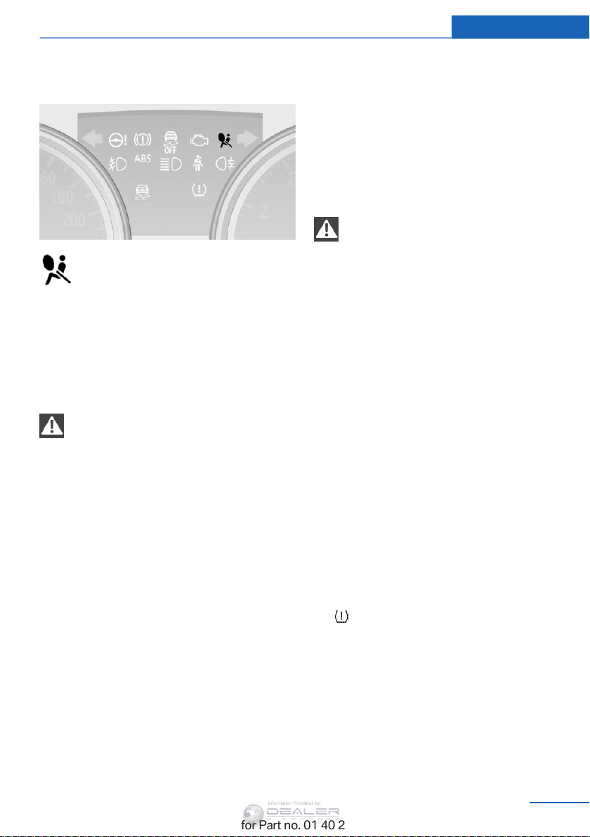
Safety Controls
Information Provided by:
Operational readiness of airbag
system
When the ignition is switched on, refer
to page 60, the warning lamp comes on
briefly to indicate that the entire airbag
system and the belt tensioners are operational.
Airbag system malfunction
▷ The warning lamp does not light up after
the ignition is switched on.
▷ Warning light remains permanently on.
Have the airbag system checked without
delay if there is a malfunction
In the event of a malfunction in the airbag sys‐
tem, have it checked without delay; otherwise,
there is the risk that the system will not func‐
tion as intended even if a sufficiently severe
accident occurs.
◀
FTM Flat Tire Monitor
The concept
The system does not measure the actual infla‐
tion pressure in the tires.
It detects a pressure loss in a tire by comparing
the rotational speeds of the individual wheels
while moving.
In the event of a pressure loss, the diameter
and therefore the rotational speed of the corre‐
sponding wheel change. This is detected and
reported as a flat tire.
Functional requirements
The system must have been initialized when
the tire inflation pressure was correct; other‐
wise, reliable signaling of a flat tire is not en‐
sured. Initialize the system after each correc‐
tion of the tire inflation pressure and after
every tire or wheel change.
System limits
Sudden tire damage
Sudden serious tire damage caused by
external influences cannot be indicated in ad‐
◀
vance.
A natural, even pressure loss in all four tires
cannot be detected. Therefore, check the tire
inflation pressure regularly.
The system could be delayed or malfunction in
the following situations:
▷ When the system has not been initialized.
▷ When driving on a snowy or slippery road
surface.
▷ Sporty driving style: slip in the drive
wheels, high lateral acceleration.
▷ When driving with snow chains.
Status display
The current status of the Flat Tire Monitor can
be displayed on the Control Display, e.g.,
whether or not the FTM is active.
1. "Vehicle Info"
2. "Vehicle status"
3.
"Flat Tire Monitor"
The status is displayed.
Initialization
The initialization process adopts the set infla‐
tion tire pressures as reference values for the
detection of a flat tire. Initialization is started by
confirming the inflation pressures.
Online Edition for Part no. 01 40 2 954 052 - II/15
93
Page 96
Controls Safety
Information Provided by:
Do not initialize the system when driving with
snow chains
.
1. "Vehicle Info"
2. "Vehicle status"
3.
"Reset"
4. Start the engine - do not drive away.
5. Start the initialization with "Reset".
6. Drive away.
The initialization is completed while driving,
which can be interrupted at any time.
The initialization automatically continues when
driving resumes.
Indication of a flat tire
The warning lamp lights up red. A
message appears on the Control Dis‐
play. In addition, a signal sounds.
There is a flat tire or a major loss in tire inflation
pressure.
Reduce your speed and stop cautiously. Avoid
sudden braking and steering maneuvers.
Do not continue driving without run-flat
tires
Do not continue driving if the vehicle is not
equipped with run-flat tires; continued driving
may result in serious accidents.◀
When a flat tire is indicated, DSC Dynamic Sta‐
bility Control is switched on if necessary.
Actions in the event of a flat tire
Run-flat tires
Maximum speed
You can continue driving with a damaged tire
at speeds up to 50 mph/80 km/h.
Continued driving with a flat tire
If continuing to drive with a damaged tire:
1. Avoid sudden braking and steering maneu‐
vers.
2. Do not exceed a speed of 50 mph/80 km/h.
3. At the next opportunity, check the inflation
pressure in all four tires.
If the tire inflation pressure in all four tires
is correct, the Flat Tire Monitor may not
have been initialized. In this case, initialize
the system.
Possible driving distance with complete loss of
tire inflation pressure:
The possible driving distance after a loss of tire
inflation pressure depends on the cargo load
and the driving style and conditions.
For a vehicle containing an average load, the
possible driving distance is ap‐
prox. 50 miles/80 km.
When the vehicle is driven with a damaged tire,
its handling characteristics change, e.g., re‐
duced lane stability during braking, a longer
braking distance, and altered self-steering
properties. Adjust your driving style accord‐
ingly. Avoid abrupt steering maneuvers or driv‐
ing over obstacles, e. g., curbs, potholes, etc.
Because the possible driving distance de‐
pends on how the vehicle is used during the
trip, the actual distance may be smaller or
greater depending on the driving speed, road
conditions, external temperature, cargo load,
etc.
Continued driving with a flat tire
Drive moderately and do not exceed a
speed of 50 mph/80 km/h.
A loss of tire inflation pressure results in a
change in the handling characteristics, e.g., re‐
duced lane stability during braking, a longer
braking distance and altered self-steering
properties.◀
94
Online Edition for Part no. 01 40 2 954 052 - II/15
Page 97
Safety Controls
Information Provided by:
Final tire failure
Vibrations or loud noises while driving
can indicate the final failure of the tire. Reduce
speed and stop; otherwise, pieces of the tire
could come loose and cause an accident. Do
not continue driving, and contact your service
center.◀
Tire Pressure Monitor TPM
The concept
The system monitors the tire pressure in the
four mounted tires. The system issues a warn‐
ing if there is a significant loss of pressure in
one or more tires. Sensors in the tire valves
measure the tire pressure.
Notes
Tire damage caused by external influen‐
ces
Sudden tire damage caused by external influ‐
ences cannot be indicated in advance.
To operate the system, also note the additional
information and instructions contained under
Tire inflation pressure, refer to page 232.
Functional requirements
The system must have been reset while the in‐
flation pressure was correct; otherwise, reliable
signaling of pressure loss is not ensured.
Reset the system after adjusting the tire infla‐
tion pressure and after changing a tire or
wheel.
Always use wheels with TPM electronics to
ensure that the system will operate properly.
Status display
1. "Vehicle Info"
2. "Vehicle status"
3.
"TPM"
The status is displayed.
◀
Status indicator on the Control
Display
The tire and system status is indicated by the
color of the tires.
A change in the tire inflation pressure during
driving is taken into account.
All wheels are green
The system is active and issues warnings in
case of deviations from the tire inflation pres‐
sures stored last.
"TPM active" appears on the Control Display.
One wheel is yellow
Flat tire or major drop in inflation pressure in
the indicated tire. A message appears on the
Control Display.
All wheels are yellow
▷ Flat tire or major drop in inflation pressure
in several tires.
▷ The system was not reset after a wheel
change and issues warnings when the tire
pressure deviates from the tire inflation
pressures stored last.
▷ A flat tire in one or more tires while the sys‐
tem is being reset.
A message appears on the Control Display.
The wheels are gray
The system cannot detect a flat tire.
Possible reasons for this:
▷ TPM is being reset.
▷ Disturbance by systems or devices with
the same radio frequency.
▷ Malfunction.
Status information
The status control display additionally shows
the current tire inflation pressures. It shows the
actual values read; they may vary depending
on driving style or weather conditions.
Online Edition for Part no. 01 40 2 954 052 - II/15
95
Page 98
Controls Safety
Information Provided by:
Resetting the system
Reset the system after adjusting the tire infla‐
tion pressure and every time a tire or wheel is
changed.
1. "Vehicle Info"
2. "Vehicle status"
3. "Reset"
4. Start the engine, but do not start driving.
5. Start the system reset with "Reset".
6. Drive away.
The tires are shown in gray and "Resetting
TPM..." is displayed.
After a short trip at over 30 km/h, the set tire
inflation pressures are adopted as target val‐
ues. The system reset is completed as you
drive, and can be interrupted at any time.
When driving resumes, the reset is continued
automatically. On the Control Display, the tires
are shown in green and "TPM active"
is dis‐
played again.
The trip can be interrupted at any time. When
driving resumes, the reset is continued auto‐
matically.
If a flat tire is detected while the system is re‐
setting, all tires on the Control Display are dis‐
played in yellow. The message "Low tire!" is
shown.
Low tire pressure message
The small warning light lights up yel‐
low and the large warning light lights
up red. A message appears on the
Control Display. In addition, a signal
sounds.
▷ There is a flat tire or a major loss in tire in‐
flation pressure.
▷ The system was not reset. The system
therefore issues warnings in case of devia‐
tions from the tire inflation pressures
stored last.
Reduce your speed and stop cautiously. Avoid
sudden braking and steering maneuvers.
Do not continue driving without run-flat
tires
Do not continue driving if the vehicle is not
equipped with run-flat tires; continued driving
may result in serious accidents.◀
When a flat tire is indicated, DSC Dynamic Sta‐
bility Control is switched on if necessary.
Actions in the event of a flat tire
Run-flat tires
Maximum speed
You can continue driving with a damaged tire
at speeds up to 50 mph/80 km/h.
Continued driving with a flat tire
If continuing to drive with a damaged tire:
1. Avoid sudden braking and steering maneu‐
vers.
2. Do not exceed a speed of 50 mph/80 km/h.
3. Check the air pressure in all four tires at
the next opportunity.
If the tire inflation pressure in all four tires
is correct, the Tire Pressure Monitor may
not have been reset. Reset the system.
Possible driving distance with complete loss of
tire inflation pressure:
The possible driving distance after a loss of tire
inflation pressure depends on the cargo load
and the driving style and conditions.
For a vehicle containing an average load, the
possible driving distance is ap‐
prox. 50 miles/80 km.
When the vehicle is driven with a damaged tire,
its handling characteristics change, e.g., re‐
duced lane stability during braking, a longer
braking distance, and altered self-steering
properties. Adjust your driving style accord‐
96
Online Edition for Part no. 01 40 2 954 052 - II/15
Page 99
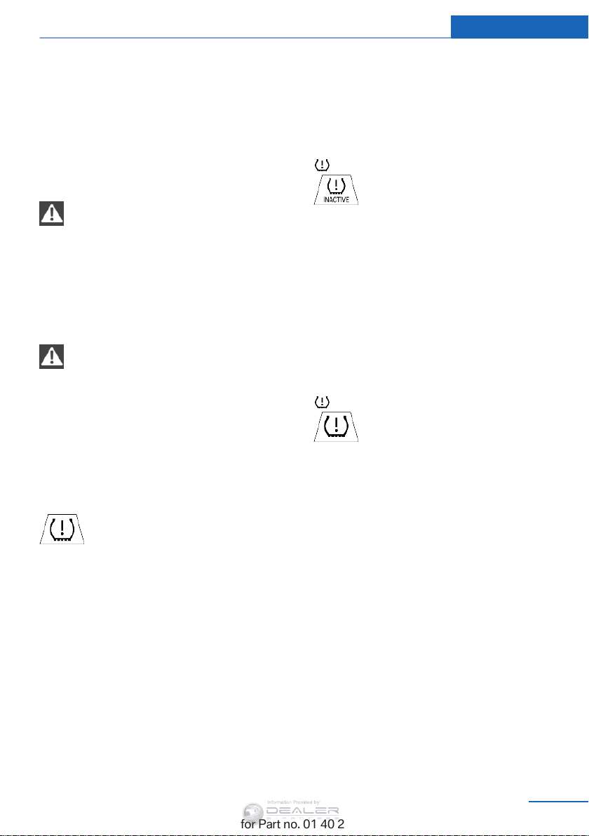
Safety Controls
Information Provided by:
ingly. Avoid abrupt steering maneuvers or driv‐
ing over obstacles, e. g., curbs, potholes, etc.
Because the possible driving distance de‐
pends on how the vehicle is used during the
trip, the actual distance may be smaller or
greater depending on the driving speed, road
conditions, external temperature, cargo load,
etc.
Continued driving with a flat tire
Drive moderately and do not exceed a
speed of 50 mph/80 km/h.
A loss of tire inflation pressure results in a
change in the handling characteristics, e.g., re‐
duced lane stability during braking, a longer
braking distance and altered self-steering
properties.◀
Final tire failure
Vibrations or loud noises while driving
can indicate the final failure of the tire. Reduce
speed and stop; otherwise, pieces of the tire
could come loose and cause an accident. Do
not continue driving, and contact your service
center.◀
Message when the system was not
reset
The yellow warning light lights up. A
Check Control message is displayed.
The system may not have been reset
although a wheel was changed.
Check the tire inflation pressure and reset the
system, refer to page 96.
System limits
The system does not function properly if it has
not been reset, e.g., it may identify a tire as flat
in spite of the fact that the tire is filled to the
correct inflation pressure.
The tire pressure depends on the temperature
of the tire. An increase in the tire temperature,
e.g., while driving or due to sunlight, increases
the tire inflation pressure. The tire pressure
decreases when the tire temperature drops. In
case of severe temperature drops, this behav‐
ior may lead to a warning on account of the de‐
fined warning limits.
Malfunction
The small warning light flashes in yel‐
low and then lights up continuously;
the larger warning light comes on in
yellow. On the Control Display, the
tires are shown in gray and a message ap‐
pears. No flat tire can be detected.
Display in the following situations:
▷ A wheel without TPM electronics is fitted:
have the service center check it if neces‐
sary.
▷ Malfunction: have the system checked by
your service center.
▷ TPM could not be fully reset. Reset the
system again.
The small warning light flashes in yel‐
low and then lights up continuously;
the larger warning light comes on in
yellow. On the Control Display, the
tires are shown in gray and a message ap‐
pears. No flat tire can be detected.
Display in the following situations:
▷ Disturbance by systems or devices with
the same radio frequency: after leaving the
area of the disturbance, the system auto‐
matically becomes active again.
Declaration according to NHTSA/
FMVSS 138 Tire Pressure Monitoring
Systems
Each tire, including the spare (if provided)
should be checked monthly when cold and in‐
flated to the inflation pressure recommended
by the vehicle manufacturer on the vehicle
placard or tire inflation pressure label (If your
vehicle has tires of a different size than the size
indicated on the vehicle placard or tire inflation
pressure label, you should determine the
proper tire inflation pressure for those tires.).
Online Edition for Part no. 01 40 2 954 052 - II/15
97
Page 100
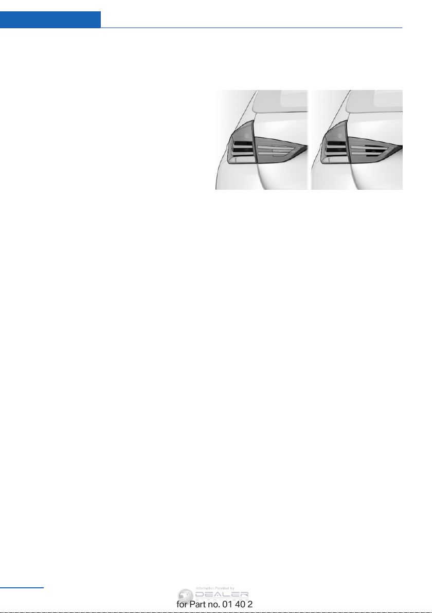
Controls Safety
Information Provided by:
As an added safety feature, your vehicle has
been equipped with a tire pressure monitoring
system (TPMS) that illuminates a low tire pres‐
sure telltale when one or more of your tires is
significantly under-inflated. Accordingly, when
the low tire pressure telltale illuminates, you
should stop and check your tires as soon as
possible, and inflate them to the proper pres‐
sure. Driving on a significantly under-inflated
tire causes the tire to overheat and can lead to
tire failure. Under-inflation also reduces fuel ef‐
ficiency and tire tread life, and may affect the
vehicle's handling and stopping ability.
Please note that the TPMS is not a substitute
for proper tire maintenance, and it is the driv‐
er's responsibility to maintain correct tire pres‐
sure, even if under-inflation has not reached
the level to trigger illumination of the TPMS
low tire pressure telltale.
Your vehicle has also been equipped with a
TPMS malfunction indicator to indicate when
the system is not operating properly. The
TPMS malfunction indicator is combined with
the low tire pressure telltale. When the system
detects a malfunction, the telltale will flash for
approximately one minute and then remain
continuously illuminated. This sequence will
continue upon subsequent vehicle startups as
long as the malfunction exists. When the mal‐
function indicator is illuminated, the system
may not be able to detect or signal low tire
pressure as intended. TPMS malfunctions may
occur for a variety of reasons, including the in‐
stallation of replacement or alternate tires or
wheels on the vehicle that prevent the TPMS
from functioning properly. Always check the
TPMS malfunction telltale after replacing one
or more tires or wheels on your vehicle to en‐
sure that the replacement or alternate tires and
wheels allow the TPMS to continue to function
properly.
Brake force display
The concept
▷ During normal brake application, the outer
brake lamps light up.
▷ During heavy brake application, the inner
brake lamps light up in addition.
98
Online Edition for Part no. 01 40 2 954 052 - II/15
 Loading...