

BMW Mountain Bike Enduro, Mountain Bike Cross Country, Touring Bike, Cruise Bike Owner's Manual
Page 1

BMW Lifestyle
Bikes & Equipment
www.bmw-shop.com
The Ultimate Driving
Machine
JOY IS POWERFULLY EFFICIENT.
OWNER’S MaNUaL.
Page 2

Suspension fork:
Fork crown
Stanchion tube
Lower leg
Drop-out
Stem
Handlebars
Brake lever
Shift lever
Headset
Rotor
Brake
Wheel:
Quick-release
Tyre
Spoke
Rim
Valve
Hub
Frame:
Top tube
Down tube
Seat tube
Chainstay
Rear stay
Rear shock
Saddle
Seat post
Seat post clamp
Brake
Cassette sprockets
Front derailleur
Rear derailleur
Chain
Chainring
Crankset
Pedal
1
1
2
3
4
6
5
I
II
III
IV
I
II
III
IV
2
3
4
5
6
BMW Mountain Bike Enduro.
Page 3

Suspension fork:
Fork crown
Stanchion tube
Lower leg
Drop-out
Stem
Handlebars
Brake lever
Shift lever
Headset
Rotor
Brake
Wheel:
Quick-release
Tyre
Spoke
Rim
Valve
Hub
Frame:
Top tube
Down tube
Seat tube
Chainstay
Rear stay
Rear shock
Saddle
Seat post
Seat post clamp
Brake
Cassette sprockets
Front derailleur
Rear derailleur
Chain
Chainring
Crankset
Pedal
1
1
2
3
4
6
5
I
II
III
IV
I
II
III
IV
2
3
4
5
6
BMW Mountain Bike Cross Country.
Page 4

Suspension fork:
Fork crown
Stanchion tube
Lower leg
Drop-out
Stem
Handlebars
Brake lever
Shift lever
Headset
Front light with reector
Front brake
Hub dynamo
Wheel:
Quick-release
Tyre
Spoke
Rim
Reector ring
Valve
Hub
Frame:
Top tube
Down tube
Seat tube
Chainstay
Rear stay
Saddle
Seat post
Seat post clamp
Pannier rack
Rear light with reector
Reector
Mudguard
Rear brake
Cassette sprockets
Front derailleur
Rear derailleur
Kickstand
Chain
Chainring
Crankset
Pedal
1
1
2
3
4
5
I
II
III
IV
I
II
III
IV
2
3
4
5
BMW Touring Bike / Cruise Bike.
Page 5
1
1 WELCOME.
Congratulations for having purchased your new BMW bicycle!
This manual contains information on the safe operation and maintenance of your BMW bicycle. Furthermore, it describes the risks and
dangers in case of incorrect handling.
Please read these instructions thoroughly before you set off for the rst
time.
Contact your BMW partner or a bicycle specialist shop of your trust for
all service or repair to be done on your bicycle.
Handover report, bicycle data and registration.
To validate your warranty, the bicycle must be handed over properly,
unless it was purchased at www.bmw-shop.com, and the handover
report completed in full. Be sure to thoroughly ll in all bicycle data into
the handover report for an easier identication, e.g. in the event of loss or
theft. The frame number of your BMW bicycle is marked on the underside of the bottom bracket shell.
Handover report: Original and copies.
Send the original to the following address of G.B.S. Global Bike Service
Ltd. There is one copy for the salesman and one copy for the buyer.
G.B.S. Global Bike Service Ltd.
Codeword: BMW Bike Registration
Wichernstraße 7
D-97525 Schwebheim
When you send the handover report to G.B.S. Global Bike Service Ltd.
your BMW bicycle will be registered. We shall be pleased to conrm the
purchase of your BMW bicycle as soon as it will be registered.
To nd more lms, downloads and information on BMW bikes as well as
further BMW lifestyle products, please visit us at www.bmw-shop.com.
In purchasing this bicycle you have chosen a product of high quality and
technology. Each component of your new bicycle has been designed,
manufactured and assembled with great care and expertise. Your BMW
partner gave the bicycle its nal assembly and performed a function
check to guarantee proper operation. You can now set off to enjoy your
new bicycle feeling safe and secure.
This manual contains a wealth of information on the proper use of your
bicycle, its maintenance and operation as well as interesting details
about bicycle design and engineering. Please read these instructions
thoroughly. We are sure that even if you have been cycling all your life
you will nd it worthwhile. Bicycle technology has developed at a rapid
pace during recent years. Therefore, before setting off on your new bicycle, be sure to read at least the chapter “Before Your FIRST Ride“.
To have as much fun as possible during cycling, be sure to carry out the
minimum functional check described in chapter “Before EVERY Ride”
before setting off. This manual cannot teach you the skills of a bicycle
mechanic. Even a manual as big as an encyclopaedia could not describe
every possible combination of available bicycles and components. It
therefore focuses on your newly purchased bicycle and standard components providing important information and warnings.
Page 6

2
When doing maintenance or repair work, be aware that the detailed
instructions provided in your manual only refer to these bicycles.
The information included here is not applicable to any other bicycle. As
bicycles come in a wide variety of designs with frequent model changes,
the routines described may not be complete. In addition, please observe
the instructions of the component suppliers that you have received from
your BMW partner.
Be aware that these instructions may require further explanation,
depending on the experience and/or skills of the person doing the work.
For some jobs you may require additional (special) tools or supplementary instructions.
For your own safety, never do work on your bicycle unless you
feel absolutely sure about it. If you are in doubt or if you have
any questions, please contact your BMW partner!
Before you set off, let us point out a few things that are very important to
every cyclist: Never ride without a properly adjusted helmet and without
glasses and take care to always wear suitable clothing. At least you
should wear straight cut trousers and shoes tting the pedal system.
Always ride carefully on public roads and observe the trafc rules so as
not to endanger yourself or others.
This manual cannot teach you how to ride. Please be aware that cycling
is a hazardous activity that requires the rider to stay in control of his or
her bicycle at all times.
Like any sport, cycling involves the risk of injury. Keep this in mind. When
you decide to ride a bicycle you need to accept the risk inherent to
cycling. Please note that on a bicycle you have no protection technology around you (e.g. bodywork, airbag) like you have in a car. Therefore,
always ride carefully and do respect the other trafc participants. Never
ride under the inuence of drugs, medication, alcohol or when you are
tired. Do not ride with a second person on your bicycle and always ride
with your hands on the handlebars.
Obser ve the legal regulations concerning off-road cycling. These regulations may differ in each country. Please respect nature when riding
off-road. Only use your bicycle on signposted, well-maintained trails and
hard-surface roads.
First we would like to familiarise you with the various components used
on your bicycle. Please unfold the cover of this manual. Here you will nd
the diagrams of three bicycles showing all the essential components.
Leave the page unfolded as you read so that you can easily locate the
components as they are referred to in the text.
Have a nice cycle trip!
Your BMW Group team
Page 7

3
IMPRINT.
Editor and photos:
BMW AG
www.bmw-shop.com
Technical details in the text and illustrations of this manual are subject to
change.
Liability of the editor, editorial department and other third parties for
articles in this brochure and damage whatsoever resulting thereof shall
be excluded, unless they are due to gross negligence.
©
No part of this publication may be reprinted, translated, copied or
transmitted in any form or by any means, e.g. electronic, mechanical, by
hand or otherwise for another business purpose without prior written
permission of the author or the editor.
Edition 1, May 2009
Page 8

4
CONTENTS.
1 Welcome. 1
Imprint. 3
1.1 General Notes on this Manual. 6
1.2 Before Your First Ride. 7
1.3 Before Ever y Ride. 9
1.4 After an Accident. 11
1.5 How to Use Quick-Releases and Thru Axles. 12
1.5.1 Quick-Releases. 12
1.5.2 Thru A xles. 14
2 Intended Use. 15
2.1 General Overview. 15
2.1.1 Cruise Bike. 15
2.1.2 Touring Bike. 15
2.1.3 Mountain Bike Cross Country and Enduro. 16
3 Legal Requirements for Riding on Public Roads. 18
4 Useful Tips for Cycling in Town and Country. 19
4.1 Safe Cycling on Public Roads. 19
4.2 Environment - Cycling Off-Road. 20
5 Brake System. 21
5.1 General Information. 21
5.1.1 Brakes – How They Work and What to Do about Wear. 22
5.2 Rim Brakes. 22
5.2.1 V-Brakes. 23
5.2.1.1 Functional Check. 23
5.2.1.2 Power Modulator. 23
5.2.1.3 Synchronising and Readjusting. 24
5.3 Disc Brakes. 24
5.3.1 Checking Hydraulic Disc Brakes. 25
5.4 Roller, Drum and Back-Pedal Brakes. 26
5.4.1 Checking and Readjusting Hand-Operated Brakes. 26
5.4.2 Checking and Readjusting Back-Pedal Brakes. 27
6 Drive System. 28
6.1 Gears. 28
6.1.1 Bottom Bracket - Crankset. 28
6.2 Derailleur Gears. 29
6.2.1 Derailleur Gears – How They Work and How to Operate
Them on Mountain, Cruise and Touring Bikes. 29
6.3 Checking and Readjusting Derailleur Gears. 30
6.3.1 Rear Derailleur. 30
6.3.2 Checking the Limit Stops. 31
6.3.3 Front Derailleur. 32
6.4 Multi-Speed Hubs (Internal Gear Hubs). 33
6.4.1 Multi-Speed Hubs - How They Work and How to Use Them. 33
6.4.2 Checking and Readjusting. 34
6.5 Combined Derailleur/Hub Gears. 34
6.5.1 Combined Derailleur/Hub Gears - How They Work and
How to Use Them. 35
6.5.2 Readjusting. 35
6.6 Crank System. 35
6.7 Chain. 36
6.7.1 Chain Maintenance. 36
6.7.2 Chain Wear. 36
6.7.3 Adjusting the Chain Tension of Single Speed Bicycles and
Multi-Speed Hubs. 37
7 Wheels and Tyres. 38
7.1 Tyres, Tubes, Rim Tape, Valves, Ination Pressure. 38
7.2 Rim Trueness, Spoke Tension. 40
7.3 Wheel Fastening with Quick-Releases. 41
7.4 Wheel Fastening with Thru Axle Systems. 41
7.5 Puncture. 42
7.5.1 Wheel Removal. 42
7.5.2 Tyre Removal (Clincher, Folding Tyres). 43
7.5.3 Tyre Mounting (Clincher, Folding Tyres). 44
7.5.4 Removal of Tubeless Tyres. 45
7.5.5 Repair of Tubeless Tyres. 45
7.5.6 Mounting Tubeless Tyres. 46
7.5.7 Wheel Mounting. 46
Page 9

5
8 Headset. 48
8.1 Checking the Headset. 48
8.2 Readjusting a Conventional Headset. 49
8.3 Readjusting an Aheadset
®
. 49
9 Suspension. 50
9.1 Glossary. 50
9.2 Suspension Forks. 51
9.2.1 Adjusting the Spring Rate. 51
9.2.2 Adjusting the Damping Control. 53
9.2.3 Adjusting the Travel. 54
9.2.4 Maintenance. 55
9.3 Rear Shock. 56
9.3.1 Adjusting the Seating Position. 56
9.3.2 Adjusting the Spring Rate. 56
9.3.3 Adjusting the Damping Control. 58
9.3.4 Maintenance. 59
10 Lighting. 61
10.1 Hub Dynamo. 61
10.2 Troubleshooting. 61
11 Adjusting the Bicycle to the Rider. 63
11.1 Adjusting the Saddle to the Correct Height. 63
11.2 Adjusting the Height of the Handlebars. 65
11.2.1 Adjustable Stems. 66
11.2.2 Conventional Stems. 67
11.2.3 Stems for Threadless Systems, the Aheadset
®
-System. 68
11.2.4 Adjusting Adjustable Handlebar Systems (A.H.S.). 68
11.3 Correcting the Fore-to-Aft Position and Tilt of the Saddle. 69
11.3.1 Adjusting Saddle Position and Tilt. 70
11.4 Adjusting the Brake Levers and the Handlebars. 71
11.4.1 Adjusting the Brake Lever Reach of Mountain, Cruise and
Touring Bikes. 71
11.4.2 Adjusting the Tilt of Handlebars, Bar Ends and Brake
Levers of Mountain, Cruise and Touring Bikes. 71
12 All About Bicycles. 73
12.1 Transporting Baggage. 73
12.1.1 Transporting Baggage with Full-Suspension Frames. 74
12.2 Taking Children with You. 74
12.2.1 Child Carriers. 74
12.2.2 Child Trailers. 75
12.2.3 Kids’ Tandem Bicycles / Trailer Systems. 76
12.3 Taking the Bicycle by Car. 77
12.4 Taking the Bicycle by Plane. 79
12.5 Accessories. 79
12.5.1 Additional Fittings. 80
12.5.2 Mudguards. 80
12.5.3 Bicycle Locks. 81
12.6 Proper Cycling Equipment. 81
12.6.1 Cycling Helmets. 81
12.6.2 Proper Cycling Clothing. 82
12.6.3 Cycling Glasses. 82
12.6.4 Shoes and Pedals. 82
13 General Notes on Care and Inspection. 85
13.1 Cleaning and Caring for the Bicycle. 86
13.2 Sheltering and Storing the Bicycle. 87
14 Service and Maintenance Schedule. 88
15 Recommended Tightening Torques. 90
16 Service Schedule (to be stamped). 92
Page 10

6
1.1 General Notes on this Manual.
The technology of today’s bicycles has become very complex. As there
is a vast range of bicycle components, this manual focuses on the most
important parts including general features. Therefore, be sure to observe the additional adjustment and/or maintenance instructions of the
respective component manufacturers that you have received from your
BMW partner together with this manual.
If you intend to do any maintenance or repair work by yourself, you
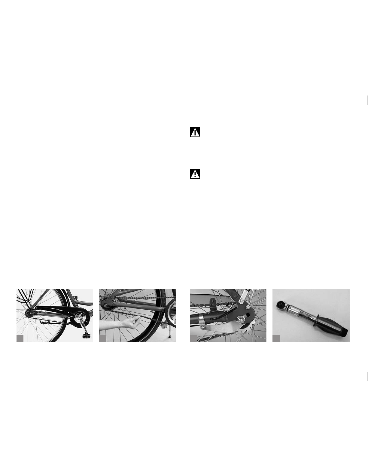
should keep in mind that today’s bicycle technology requires a considerable amount of know-how as well as special tools (a), such as e.g. a
torque wrench (b). Have your bicycle ser viced by your BMW partner to
be on the safe side.
The following information refers to your bicycle by using the specic
technical terms. Therefore, make yourself familiar with your bicycle.
Please unfold the front cover of this manual. You will nd the diagrams
of three bicycles showing the components found on your bicycle. Leave
the page unfolded as you read so that you can easily locate the components as they are referred to in the text.
The table of contents will quickly lead you to the part you are interested
in.
This symbol signies a warning that you should strictly observe
in view of your own safety and that of others and to prevent
your BMW bicycle from damage.
This symbol provides you with information or details on how to
make the most of your BMW bicycle.
Please note that the aforementioned consequences will not be repeated
each time the symbols appear in the manual.
This manual does not help you to assemble a bicycle from individual
parts, to repair it or to make a partly assembled bicycle ready-for-use!
Technical details in the text and illustrations of this manual are subject to
change.
This manual complies with the requirements of the European standards
EN 14764 and EN 14766.
In addition, please observe the included instructions of the component
manufacturers. This manual is subject to European law. If delivered to
countries outside Europe, supplementary information has to be provided
by the bicycle manufacturer.
This manual does not provide any information on frames and
components made of carbon! Misuse of carbon parts may
result in material failure, breakage and accidents. In case you
want to t your bicycle with carbon components, please read
the instructions included with these components thoroughly!
If you are in doubt or if you have any questions, please contact
your BMW partner!
ba
Page 11
7
b
c
da
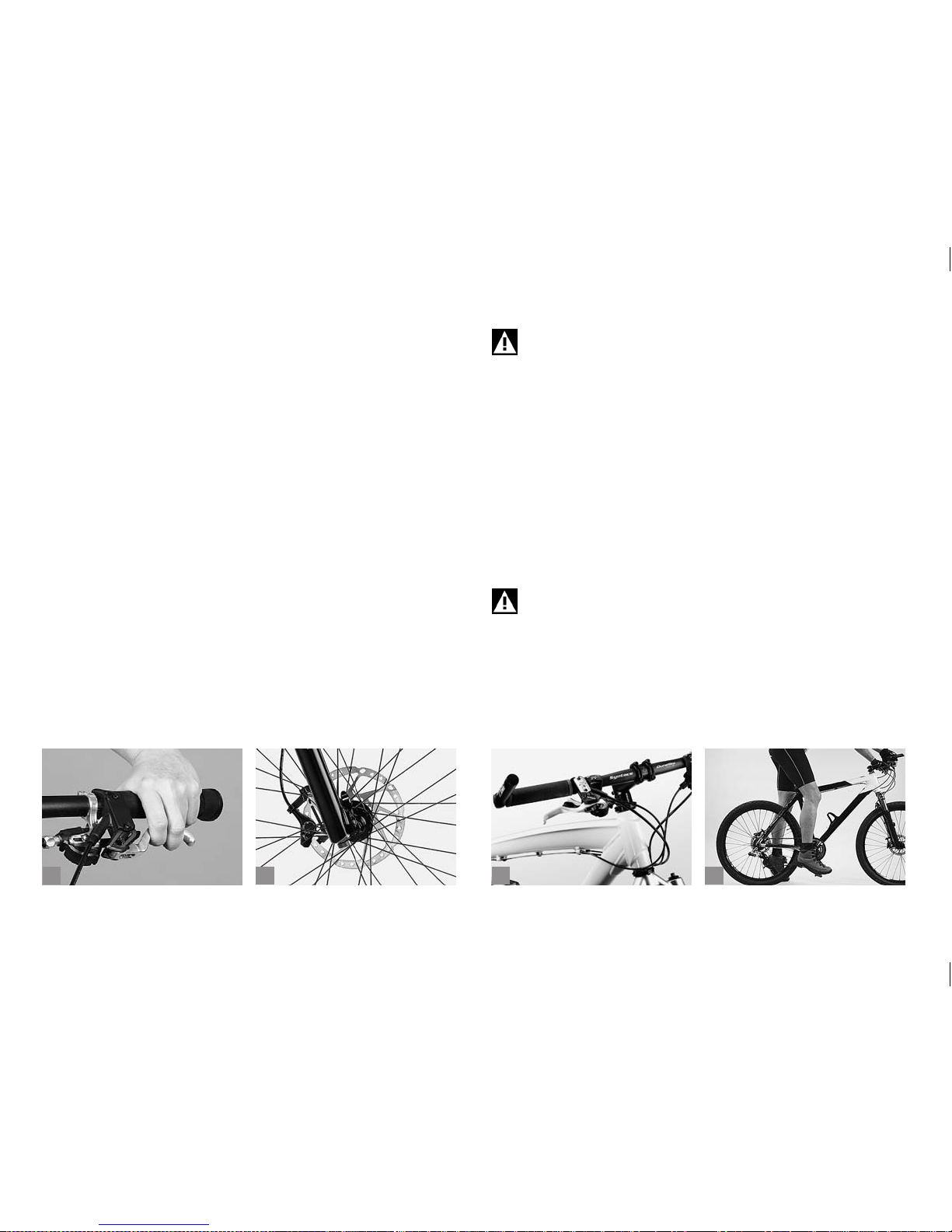
1.2 Before Your First Ride.
1. Be sure to use your bicycle only for its intended purpose, as it may
otherwise not stand up to the stress and fail! Risk of accident!
For more information on the intended use read chapter “Intended
Use”.
2. The maximum overall weight (including rider, baggage and bike) your
bicycle is designed for is specied in chapter “Intended Use”.
3. Are you familiar with the brakes (a)? Check whether the lever of the
front brake is in the position you are used to (right or left). If it is not,
you will need to learn to get used to it, as inadvertent use of the front
brake can throw you off your bicycle. Or ask your BMW partner to
switch the brake levers.
Your new bicycle is equipped with modern brakes (b) which may be
far more powerful than those you were used to so far! Be sure to rst
practise using the brakes on a level, non-slip surface off public roads!
For more information see chapter “Brake System”.
Note that the distance you need to stop your bicycle increases,
while riding with your hands on bar ends (c). The brake levers
are not always within easy reach.
4. Are you familiar with the type and functioning of the gears? If not,
make yourself familiar with the gears in a place free of trafc.
For more information see chapter “Drive System”.
5. Are both saddle and handlebars properly adjusted? Check whether
your toes reach to the oor when you are sitting on the saddle (d).
Your BMW partner will be pleased to help you if you are not happy
with your seating position.
For more information see chapter “Adjusting the Bicycle to the
Rider”.
Make particularly sure there is enough space between your
crotch and the top tube so that you do not hurt yourself, if you
have to get off your bicycle quickly.
Page 12
8
a
b
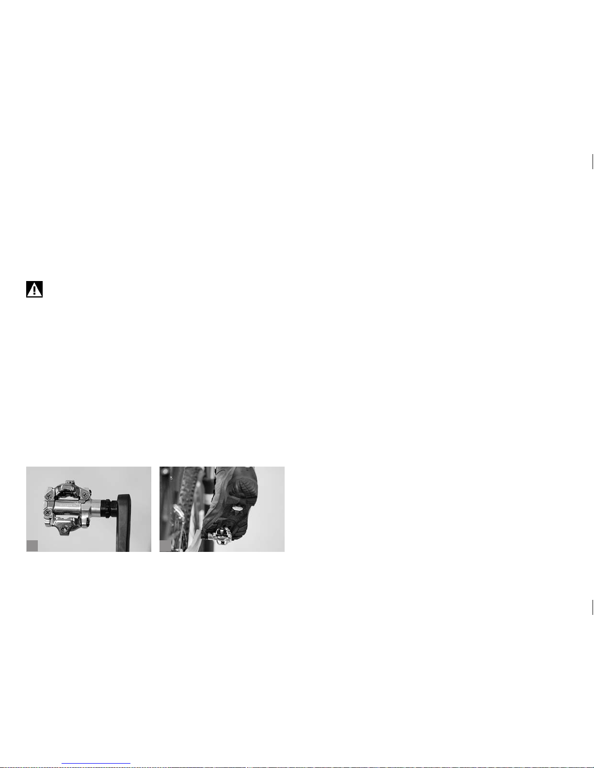
6. If your bicycle is equipped with clipless or step-in pedals (a), do not
set off until you have practised engaging and disengaging the shoes
from the pedals while stationary (b).
For more information see chapter “Proper Cycling Equipment”.
Be sure to also read the operating instructions for the pedals delivered by your BMW partner.
A lack of practice when using clipless pedals or too much
spring tension in the mechanism can lead to a very rm connection, from which you cannot quickly step out! Risk of
accident!
7. If you have bought a suspension bicycle, you should ask your BMW
partner to adjust the suspension mechanism to your needs before
delivery. If you have bought it at ww w.bmw-shop.com, ask at a bicycle specialist shop of your trust to do this job. Improperly adjusted
suspension components are liable to malfunction or damage. In any
case they will impair the performance of your bicycle as well as your
safety whilst riding.
For more information see chapters “Suspension Forks” and
“Rear Shock”. Further notes regarding full suspension bicycles and
forks may be enclosed with this manual.
Page 13
9
1.3 Before Every Ride.
Your bicycle has undergone numerous tests during production and a
nal check has been carried out by your BMW partner. Nevertheless,
be sure to check the following points to exclude any malfunctioning that
may be due to the transport of your bicycle or to work a third person may
have performed on your bicycle before delivery:
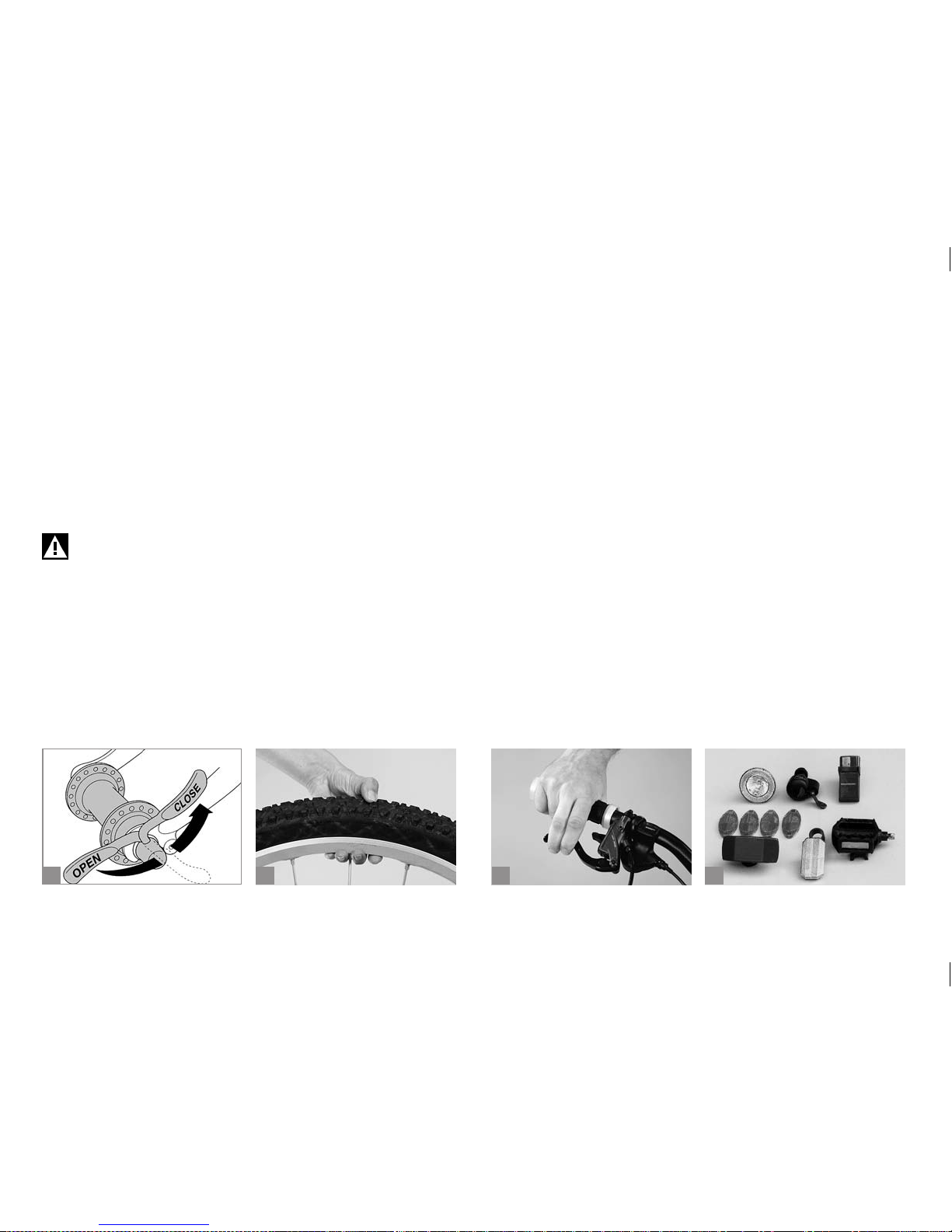
1. Are the quick-release levers of the front and rear wheel properly
closed and the bolts of the seat post and other components correctly
tightened (a)? For more information see chapter “How to Use
Quick-Releases and Thru Axles”.
Improperly closed quick-releases can cause bicycle components to come loose. Risk of accident!
2. Are the tyres in good condition and do they have sufcient pressure?
Make a “thumb test“ (b).
For more information see chapter “Wheels and Tyres”.
3. Spin the wheels to check whether the rims are true. Watch the gap
between rim and brake pad or, in the case of disc brakes, between
frame and rim or tyre. Untrue rims can be an indication of tyres with
ruptured sides or broken axles or spokes.
For more information see chapter “Wheels and Tyres”.
4. Test the brakes while stationary by rmly pulling the brake levers
towards the handlebars (c). The brake pads of rim brakes must hit the
rim with their entire surface without touching the tyre. You should not
be able to pull the lever all the way to the handlebars! The same applies to the brake levers of disc brakes. You should not be able to pull
them all the way to the handlebars! Make sure there is no brake uid
leakage. Also check the thickness of the brake pads.
For more information see chapter “Brake System”.
5. Let your bicycle bounce on the ground from a small height. If there
is any rattling, check where it comes from. Check the bearings and
bolts, if necessary.
6. If you want to ride on public roads, make sure your bicycle is
equipped according to the regulations of your countr y (d). Riding
without lights and reectors in dark or dim conditions is very dangerous, because other road users will see you too late or not at all. A set
of lights that corresponds to the regulations is a must on public roads.
Turn on the lights as soon as dusk sets in.
For more information see chapter “Legal Requirements for Rid-
ing on Public Roads“.
b
c
da
Page 14
10
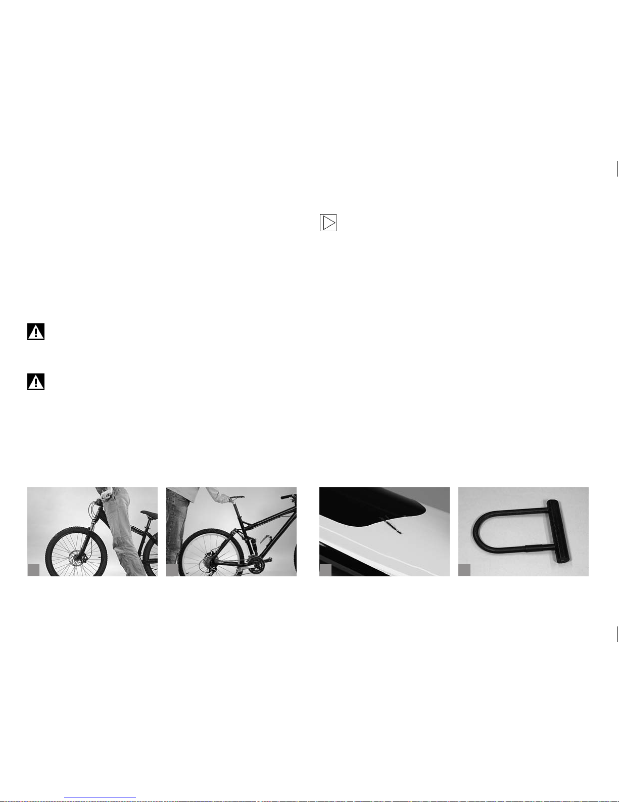
7. If your bicycle has suspension, check the frame: Press down on your
bicycle and see whether the spring elements retract and extend as
usual (a+b).
For more information see chapters “Suspension Forks” and
“Rear Shock”. Further notes regarding full suspension bicycles and
forks may be enclosed with this manual.
8. If your bicycle has a kickstand, make sure it is fully raised before you
set off. Risk of accident!
Do not use your bicycle, if it fails on one of these points! Riding
a defective bicycle can result in serious accidents! If you are in
doubt or if you have any questions, please contact your BMW
partner!
During use your bicycle is undergoing stress resulting from the
surface of the road and through the rider’s action. Due to these
dynamic loads, the different parts of your bicycle react with
wear and fatigue. Please check your bicycle regularly for wear
marks, scratches (c), bent parts, colour changes and any indication of cracking. Parts which have reached the end of their
lifespan may break without previous warning. Let your BMW
partner maintain and service your bicycle regularly and in cases
of doubt it is always best to replace parts.
Do not forget to take a high quality D- or chain lock (d) with you
on your ride. The only way to effectively protect your bicycle
against theft is to lock it to an immovable object.
b
c
da
Page 15

11
1.4 After an Accident.
1. Check whether the wheels are still rmly xed in the drop-outs and
whether the rims are still centred with respect to the frame or fork.
Spin the wheels. If the width of the gap changes markedly and you
cannot true the rim where you are, you will need to open the rim
brakes a little so that the rim can run between the brake pads without
touching them. Caution: This will reduce the braking performance.
For more information see chapters “Brake System” and “Wheels
and Tyres”.
2. Check that handlebars and stem are neither bent nor broken and that
they are level and upright. Make sure the stem is rmly xed on the
fork by taking the front wheel between your knees and by trying to
twist the handlebars relative to the front wheel (a). Briey lean on the
brake levers to make sure the handlebars are rmly xed in the stem.
For more information see chapters “Adjusting the Bicycle to the
Rider” and “Headset”.
3. Check whether the chain still runs on the chainrings and sprockets (b). If your bicycle fell over on the chain side, verify the proper
functioning of the gears. Ask somebody to lift the bicycle by the
saddle and gently shift through all the gears. Pay particular attention
when shifting to the small gears, making sure the rear derailleur does
not get too close to the spokes as the chain climbs onto the larger
sprockets (c). If the rear derailleur or the drop-outs are bent, this can
cause the rear derailleur to collide with the spokes and result in an
accident! This in turn can destroy the rear derailleur, the rear wheel or
the frame. Check the front derailleur, as a damaged gear changer can
throw off the chain, thus interrupting the power train of the bicycle
(see chapter “Drive System”).
4. Make sure the saddle is not twisted using the top tube or the bottom
bracket shell as a reference (d).
5. Lift your bicycle up a few centimetres and let it bounce onto the
ground. If this causes any sort of noise, search for loosened bolts or
components.
6. Finally, take a good look at the whole bicycle to detect any deformations, discolourations or cracks.
Only if your bicycle passed these checks without any problems should
you ride back very carefully, taking the shortest possible route. Do not
brake hard or accelerate and do not ride your bicycle out of the saddle.
If you are in doubt about the performance of your bicycle, have yourself picked up by car, instead of taking any risk. Back home you need
to check your bicycle thoroughly. If you are in doubt or if you have any
questions, please contact your BMW partner!
Bent parts made of aluminium must not be repaired, i.e.
straightened, as the risk of breakage would still remain. This
applies in particular to forks, handlebars, stems, cranksets and
pedals. Be sure to replace them as a precaution.
b
c
da
Page 16
12
b
c
da
1.5 How to Use Quick-Releases and Thru
Axles.
1.5.1 Quick-Releases.
Your bicycle is tted with quick-releases to ensure fast adjustments,
assembly and disassembly. Be sure to check whether all quick-releases
are tight before you set off on your bicycle. Quick-releases should be
handled with great care, as they directly af fect your safety.
Practise the use of quick-releases to avoid any accidents.
Quick-release mechanisms essentially consist of two operative elements:
1. The hand lever on one side of the hub which creates a clamping force
via a cam when you close it (a).
2. The tightening nut on the other side of the hub with which the initial
tension on the threaded rod is set.
Make sure the levers of both quick-releases at the front and
rear wheel are always on the side opposite to the chain. This
will help you to avoid mounting the front wheel the wrong way
round. By contrast, with disc brakes the front quick-release is
usually mounted with its lever to the right.
Never ride a bicycle without having rst checked whether the
wheels are securely fastened! A wheel that comes loose whilst
riding will throw you off your bicycle!
If your bicycle is equipped with quick-releases, be sure to lock
the frame to an immovable object together with the wheels
when you leave it outside.
How to Fasten Components Securely.
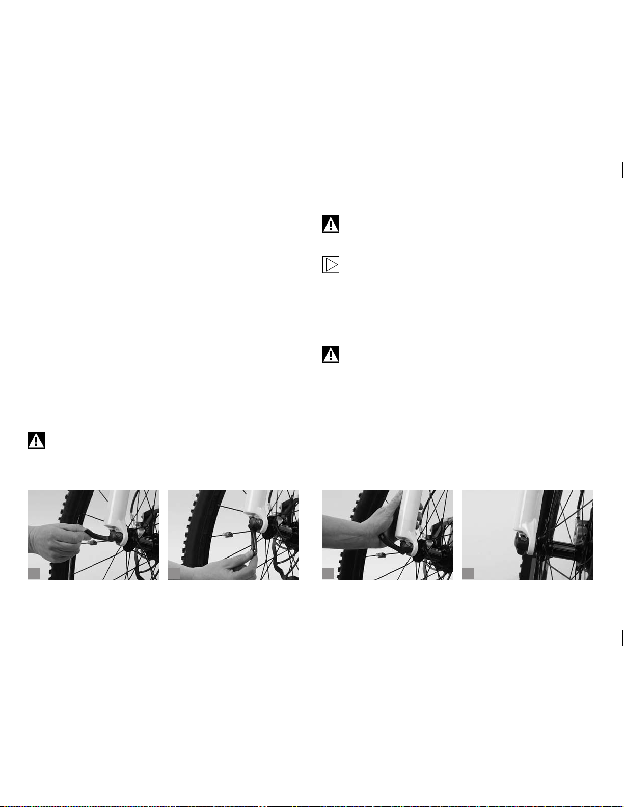
Open the quick-release. The marking “Open“ on the lever should become visible now (b).
Do not touch the rotor directly after stopping – you may burn
your ngers! Always let the rotor cool down before opening the
quick-releases!
Move the lever back, as if to close it. Now you should be able to read
”Close“ on the outside of the lever. When you start closing the lever you
should feel virtually no resistance with your hand until the lever is at right
angle to the frame/fork.
Over the second half of its travel the resistance you feel should increase
signicantly. Towards the end of its travel you should need very much
strength to close the lever. Use the ball of your thumb to push it in all the
way while your ngers pull on an immovable part, such as the fork or the
rear stay (c), but not on a rotor or spoke.
Page 17

13
b
c
da
In its end position, the lever should be parallel to the bicycle, i.e. it should
not stick out to the side ((d) p. 12). The lever should lie close to the
frame or the fork so that it cannot be opened accidentally.
To check whether the lever is securely locked apply pressure to the end
of the hand lever and try to turn it while it is closed. If you can turn the
lever around, open it and increase the initial tension. Screw the tightening nut on the opposite side clockwise by half a turn. Close the lever and
check it again for tightness.
Finally, lift the bicycle a few centimetres so that the wheel no longer
touches the ground and hit the tyre from above (a). If it is properly
fastened, the wheel will remain rmly xed in the drop-outs of the frame
without any rattling noise.
If your seat post is equipped with a quick-release mechanism, check
whether the saddle is rmly xed by trying to twist it relative to the frame
(b).
With insufciently closed quick-releases and thru axles the
wheels can come loose, thus creating a serious risk of accident!
If your bicycle is equipped with quick-releases (c), be sure to
lock the frame to an immovable object together with the wheels
when you leave it outside.
As an anti-theft measure you can replace the quick-releases
by special locks (d). They can only be opened and closed with
a special, coded key or an Allen key. If you are in doubt or if you
have any questions, please contact a bicycle specialist shop of
your trust!
With the DT Swiss RWS system the clamping force is not created via
a cam, but by tightening a bolted connection with a lever.
Tighten the system by turning the lever clockwise while holding the
clamping nut tight.
Depending on frame or fork the lever may touch either frame or fork during tightening. If it does, pull out the lever, turn it back, let it engage again
before retightening.
In its end position, the lever should be parallel to the bicycle, i.e. it should
not stick out. The lever should lie close to the frame or the fork so that it
cannot be opened accidentally.
Finally, lift the bicycle a few centimetres so that the wheel no longer
touches the ground and hit the tyre from above. If it is properly fastened,
the wheel will remain rmly xed in the drop-outs of the frame without
any rattling noise.
Page 18
14
b
c
da
1.5.2 Thru Axles.
Thru axles are mounted when the bicycle has to withstand high stress
occurring e.g. during freeriding, downhill riding etc. or jumps. They provide suspension forks with a suitable stiffness.
Before mounting or replacing a fork/wheel combination, be
sure to read the operating instructions of the respective sus-
pension fork or wheel manufacturer rst.
Notes on How to Mount Thru Axle Wheels.
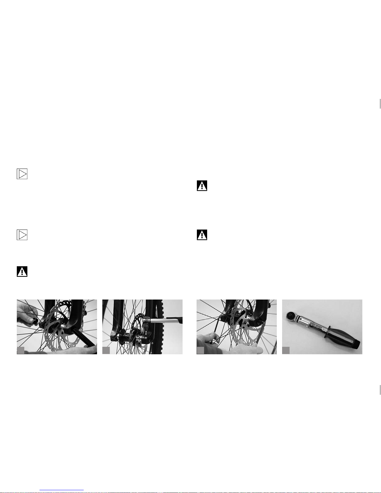
There is a wide range of thru axle systems available now. Some systems
are tightened with quick-releases. Other systems may require special
tools for assembly or disassembly (a+b).
Be sure to read the respective manual before doing any assembly work.
If you are in doubt or if you have any questions, please contact a bicycle
specialist shop of your trust!
Improperly mounted wheels may throw you off your bicycle or
result in serious accidents!
Check the fastening after one to two hours in use and then ever y 20
hours of use.
For the removal of the front wheel you may need tools (c) depending on
fork manufacturer and thru axle system. To remove the wheel, loosen
the axle support at the fork and remove the axle completely from the
hub.
To remount the front wheel proceed in the reverse order. Make sure all
bolts/quick-release systems are tightened properly.
To mount the axle use only the tools recommended by the
manufacturer. Make it a rule to use a torque wrench (d). Tighten
carefully by approaching the prescribed maximum torque in
small steps (0.5 Nm increments) whilst constantly checking the
proper t of the component. Never exceed the maximum tightening torque indicated by the manufacturer! A too tight xing of
the axle can damage the axle or the fork leg.
Check the bolts after one to two hours of use and then every 20
hours.
Page 19
15
b
c
da
2 INTENDED USE.
2.1 General Overview.
Please follow the tips provided in section “Safe Cycling on
Public Roads” in chapter “Useful Tips for Cycling in Town
and Country”.
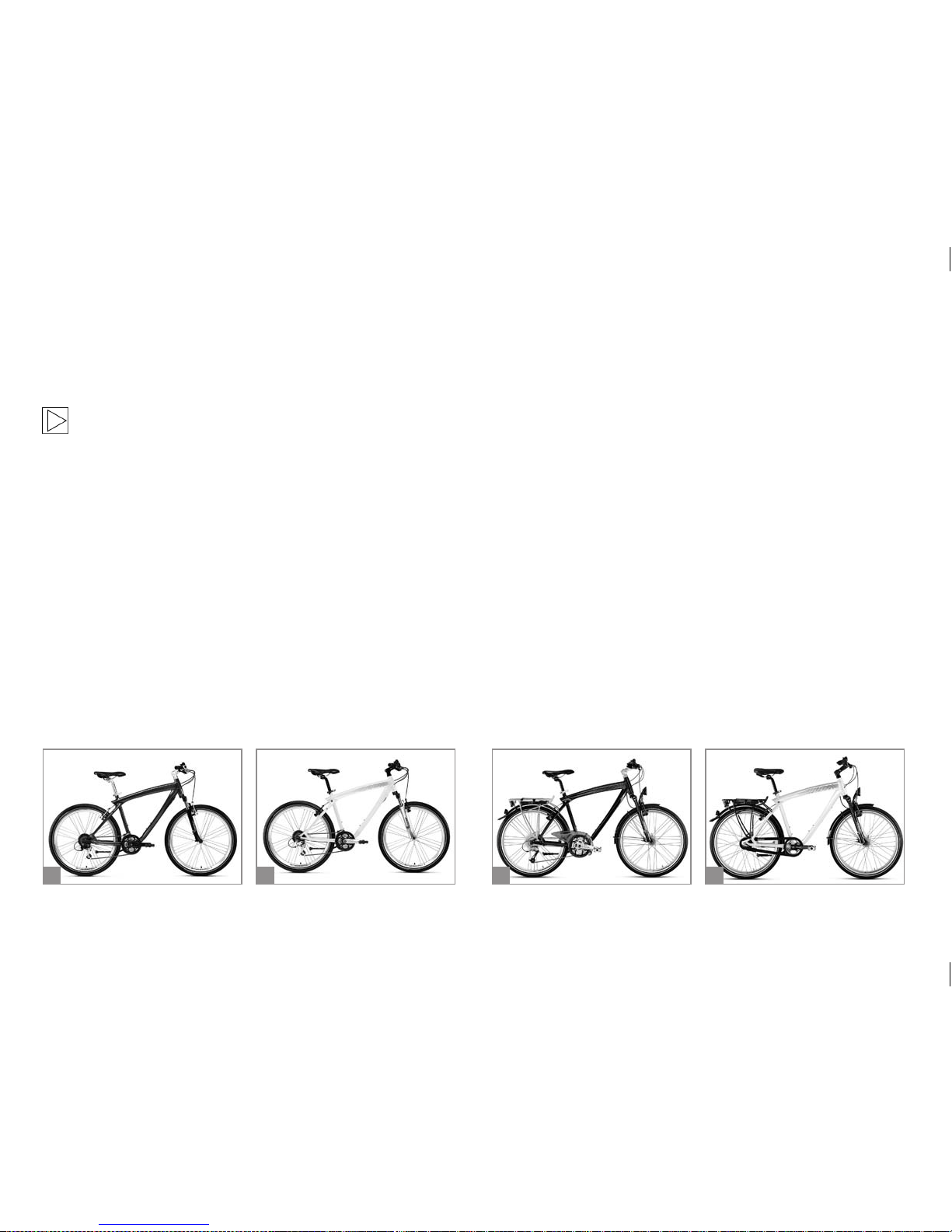
2.1.1 Cruise Bike (a+b).
Due to their design and equipment this type of bicycle is not intended to
be used on public roads. If you intend to use this type of bicycle on pub-
lic roads, it must be tted with the devices and equipment prescribed
for this purpose (see chapter “Legal Requirements for Riding on
Public Roads”).
These bicycles are for cycling off public roads on hard-surface tracks,
trails and bicycle routes through forests.
Cruise bikes are designed for a permissible overall weight (accumulated
weight of rider, baggage, trailer load and bicycle) of 125 kg.
The safety-relevant equipment and components required for these
bicycles are included in the delivery. Their reliable functioning has to be
checked by the user or BMW partner at regular intervals and repaired,
if necessary. This type of bicycle is not designed for any other use than
the intended one. Non-observance of the intended use or non-compliance with the safety-relevant information in this manual may result in
failure of the bicycle. Manufacturers and BMW partners cannot be held
liable for damage resulting thereof.
This type of bicycle is not suitable for riding off-road or in any kind of
competition.
2.1.2 Touring Bike (c+d).
Due to their design and components, e.g. with active and passive lighting devices, this type of bicycle is intended to be used on public roads
and hard-surface tracks. Furthermore, it can be used for riding on easy
terrain, e.g. on tracks and designated bicycle routes through the forests.
Permissible overall load 140 kg. Maximum trailer load 40 kg. The maximum weight limit for pannier racks is 25 kg.
Page 20
16
b
c
da
The safety-relevant equipment and components required for these
bicycles are included in the delivery. Their reliable functioning has to be
checked by the user or BMW partner at regular intervals and repaired,
if necessary. This type of bicycle is not designed for any other use than
the intended one. Non-observance of the intended use or non-compliance with the safety-relevant information in this manual may result in
failure of the bicycle. Manufacturers and BMW partners cannot be held
liable for damage resulting thereof.
This type of bicycle is not suitable for any kind of competition.
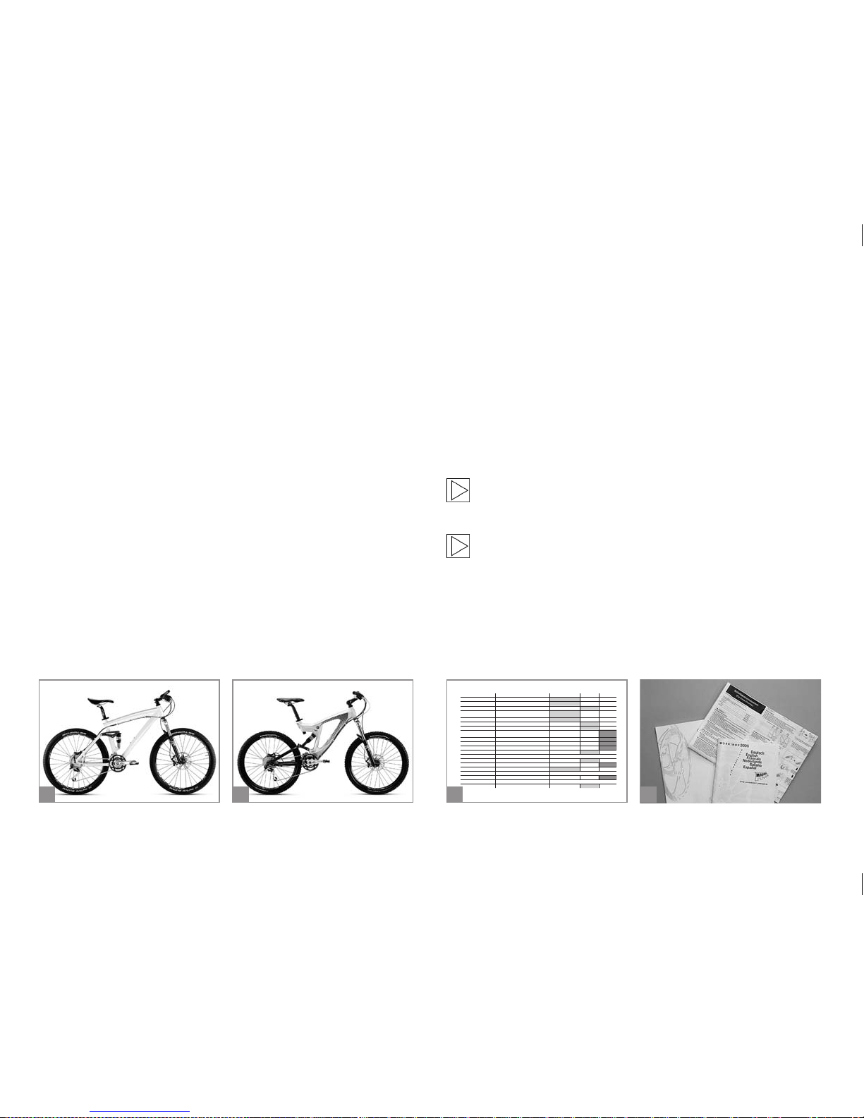
2.1.3 Mountain Bike Cross Country (a) and Enduro (b).
Due to their design and equipment this type of bicycle is not intended to
be used on public roads. If you intend to use this type of bicycle on pub-
lic roads, it must be tted with the devices and equipment prescribed
for this purpose (see chapter “Legal Requirements for Riding on
Public Roads”).
Mountain bikes are designed to be used for off-road cycling and for
riding over natural terrain (e.g. terrain of a mountain bike marathon and
cross-country racing).
Mountain / cross bicycles are designed for a permissible overall weight
(accumulated weight of rider, baggage in rucksack and bicycle) of
120 kg. Not suitable for child carrier and trailer mounting!
The safety-relevant equipment and components required for cycling
off road are included in the delivery. Their reliable functioning has to be
checked by the user or BMW partner at regular intervals and repaired,
if necessary. This type of bicycle is not designed for any other use than
the intended one. Non-observance of the intended use or non-compliance with the safety-relevant information in this manual may result in
failure of the bicycle. Manufacturers and BMW partners cannot be held
liable for damage resulting thereof.
This type of bicycle is neither suitable for downhill riding/freeride parks,
jumps, drops etc., nor for competitive use, such as downhill, dual slalom,
freeride races etc.
The intended use of all types of bicycles also includes the
observance of the tightening torques, maintenance and service
intervals, as prescribed on pages 88 to 91 of this manual (c).
Any information of the present manual is given in general
terms for different types of bicycles and therefore may require
supplementary details for some bicycles. For this reason, be
sure to also obser ve the operating instructions of individual
component manufacturers that are provided together with
your bicycle (d). In the event these accompanying documents
shall not answer all your questions, please contact your BMW
partner or a bicycle specialist shop of your trust. They will be
pleased to help you.
14 SERVICE AND MAINTENANCE SCHEDULE.
Component What to do Before every ride Monthly Annually
Lighting Check
Tyres Check pressure
Tyres Check tread and side walls
Brakes (rim-) Check lever tr avel, wear of brake pads, po sition of
pads relative to rim
Brakes (rim-) Test brakes in stationa ry
Brakes, (rim-), brake pads Clean
Brake cables Visual inspe ction
Brakes (disc-) Replace liquid
(Dot-liquids)
Suspension fork Check and retighten bolts, if necessary
Suspension fork Change oil or grease elastomers
Suspension seat post Service
Suspension seat post Check for play
Rims with rim brakes Check thickness , replace if necessa ry At the latest after se cond set of brake pads is worn d own
Bottom bracket Check for play
Bottom bracket Regrease (shell)
Chain Check and grease, if necessary
Chain Check and replace, if necessary After 800 k m (620 miles)
Crankset Check and retighten, if necessary
Painted / anodised surfaces Impregnate At l east every 6 months
Wheels / spokes Check for trueness and tension
Page 21
17
ba
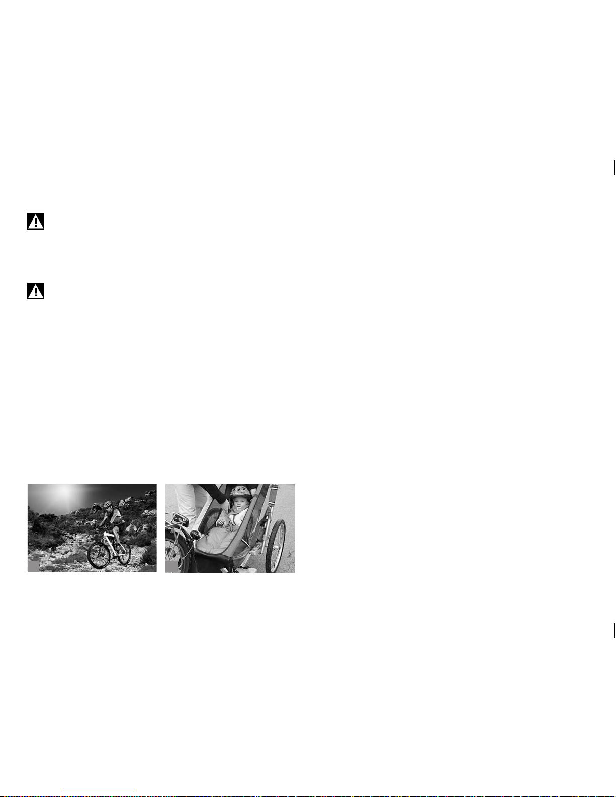
Bicycles that are delivered together with the present manual
are only designed for single person use (a) and not for freehand cycling. Overstress may result in breakage or failure of
essential components, such as e.g. frame, handlebars or fork.
This can lead to an accident with unforeseeable consequences
resulting in death!
Trailers (b) must be mounted to models with hydraulic brake
systems only! Only use suitable trailers that were mounted
professionally at a bicycle specialist shop of your trust. Full
suspension models are generally not approved for trailer
mounting.
Page 22
18
ba
3 LEGAL REQUIREMENTS FOR
RIDING ON PUBLIC ROADS.
If you use your bicycle for riding on public roads, it has to be equipped
according to the regulations of your country.
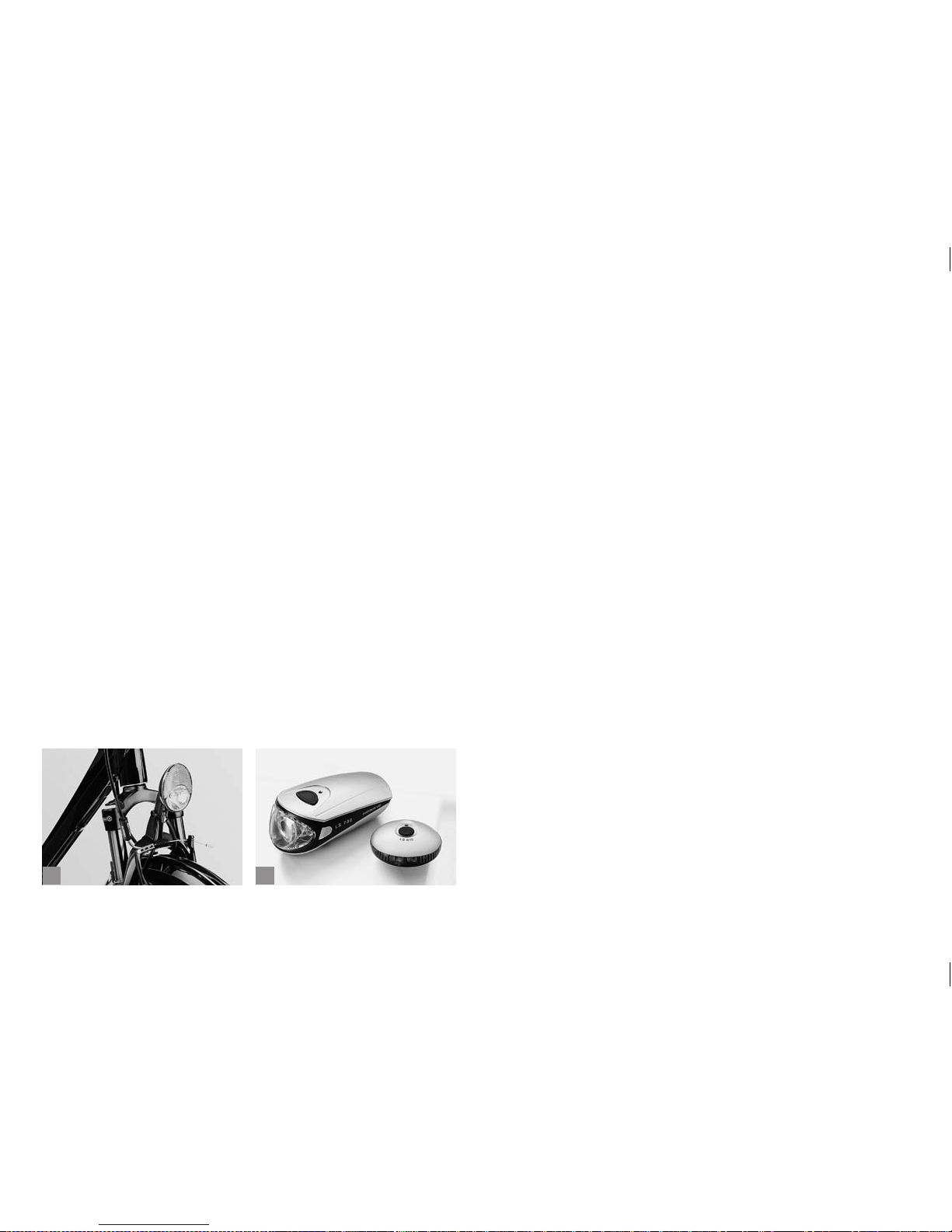
Pay particular attention to your bicycle being equipped with the prescribed lighting set (a+b) and reectors. Contact your BMW partner or
a bicycle specialist shop of your trust and ask for information about the
regulations in force in your country. Make yourself familiar with the road
trafc regulations for riding on public roads and off-road.
Page 23
19
ba
4 USEFUL TIPS FOR CYCLING IN
TOWN AND COUNTRY.
4.1 Safe Cycling on Public Roads.
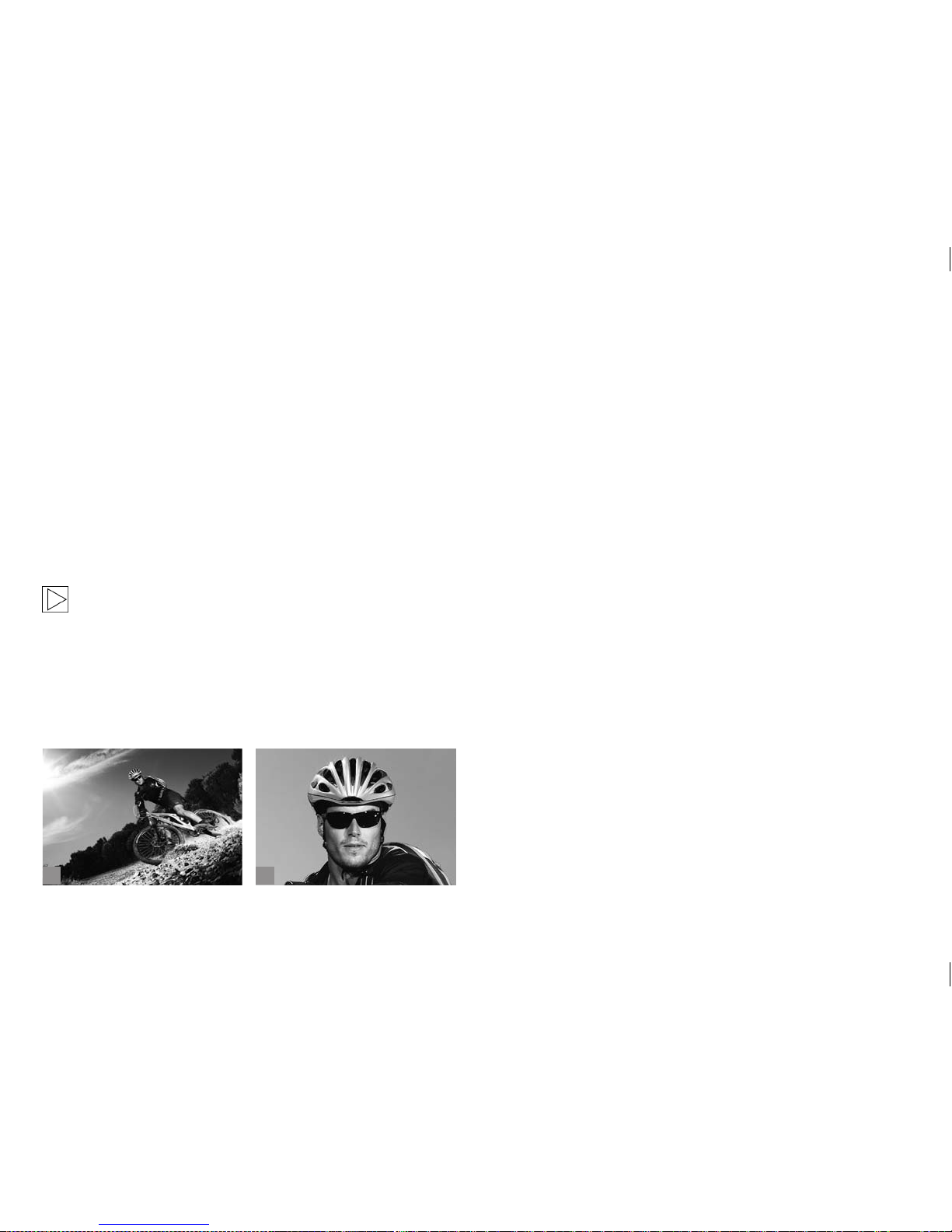
Keep in mind your bicycle is not only sports equipment (a), but also an
eco-friendly means of transport. Many cities and villages are very committed to improving cycling conditions by creating cycle lanes and by allowing cyclists to ride the wrong way up one-way streets. When you set
off on your bicycle always be aware that you are among the vulnerable
road user groups. Bicycles do not have airbags, safety belts or a crush
zone. A collision may have serious long-term negative consequences to
your health. For this reason it is very important for you to ride with caution and try to avoid dangerous situations beforehand.
This manual cannot teach you how to ride or make you familiar
with all rules of conduct on public roads. For more information
please contact a road safety organization in your country, a
bicycle club or comparable organizations.
Tips on how to ride safely on public roads:
a) Ensure your bicycle is roadworthy.
b) Make yourself familiar with the trafc rules in your country.
c) Ride with caution. Do not endanger or provoke other road users.
d) Cycling is not allowed on motorways. Danger to life! Please check
the regulations in your country.
e) For safety reasons you are not allowed to listen to music through
headphones on public roads. Do not use your mobile either.
f) Keep sufcient distance between you and the vehicles ahead. Their
stopping distance is usually signicantly shorter.
g) In wet conditions please cycle with caution. With less grip your stop-
ping distance will get longer. At about 18 kmh (11 mph) you make
about 5 metres per second. In wet conditions the stopping distance
is twice to three-times as long as in dry conditions. Adapt your riding
habits to the ever changing conditions on the street. Be sure to cycle
at moderate speed and do not brake too late.
h) Switch on the lighting in poor visibility conditions, such as fog, rain,
dawn, dusk and darkness. Bright clothing will help you to get noticed,
especially in poor light. Be sure to wear straight cut trousers or straps
or cycle clips when you set off on your bicycle. A helmet and protective glasses (b) are a must for cycling safely.
Page 24
20
ba
i) The following places are typical accident blackspots, where you
should cycle with particular caution:
• Junctions, even with a cycle lane parallel to the road; danger by cars
running in the same direction and turning to the left or right; danger
by oncoming trafc.
• Crossing railway tracks can be hazardous for cyclists, as a trapped
front wheel can throw the cyclist off. Be sure to cross railway tracks at
right angle.
• With a truck or bus besides you, e.g. in front of trafc lights. You may
be overlooked by the driver and are at risk of being run over when the
truck or bus turns to the left or right.
• On cycle lanes: take care of loose dogs and children crossing the lane
unmindfully.
Make yourself familiar with the trafc rules before cycling on
public roads. Anticipate the mistakes of other road users!
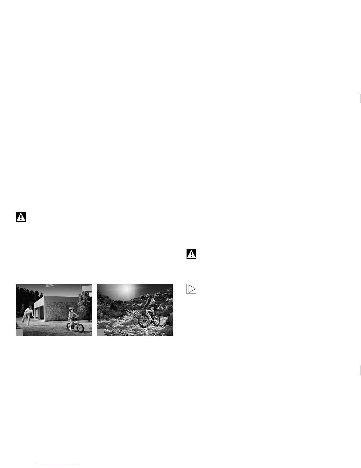
Parents should take their time to introduce their children (a) to safe
cycling on public roads. In Germany e.g. children must cycle on pavements until the age of eight. Between the age of eight and ten they are
still allowed to do so. For crossing the street, children must get off their
bicycle.
Parents are advised to sign their children up to courses where they learn
how to safely cycle on public roads offered by road safety organizations
or the like.
4.2 Environment - Cycling Off-Road.
A bicycle is the ideal means of transport for any nature lover (b). Today,
cycling plays a major role in recreational activities. Cycling through parks
and forest trails has become most popular. To protect nature and avoid
conicts between cyclists, hikers and municipal authorities it is crucial
that certain basic rules are followed.
To protect wildlife habitat and the ora, please ride on signposted tracks
and lanes only and avoid any off-road cycling across grassland, elds
and through forest. Never ride through waters! Be sure when riding off
road that you do not ride faster than your cycling skills allow.
Always be respectful to walkers and hikers and ready to brake when riding downhill or if the road ahead is not clear. Mind your speed and do not
leave skid marks. Please throw your litter in litter bins or take it home.
Ensure an environmentally friendly disposal of lubricants, cleaning and
care products after use. These agents must not be disposed of with
domestic waste, in nature or emptied into drains.
Cycling off-road requires a great deal of skill, physical tness and full concentration. Start with easy cycling tours and
increase the degree of difculty step by step. Please note that
though looking easy, the tricks of a professional actually require
years of training. Do not overestimate your riding skills!
Mountain bikers will nd further information at International
Mountain Bicycling Association (www.imba.com).
Page 25
21
b
c
da
5 BRAKE SYSTEM.
5.1 General Information.
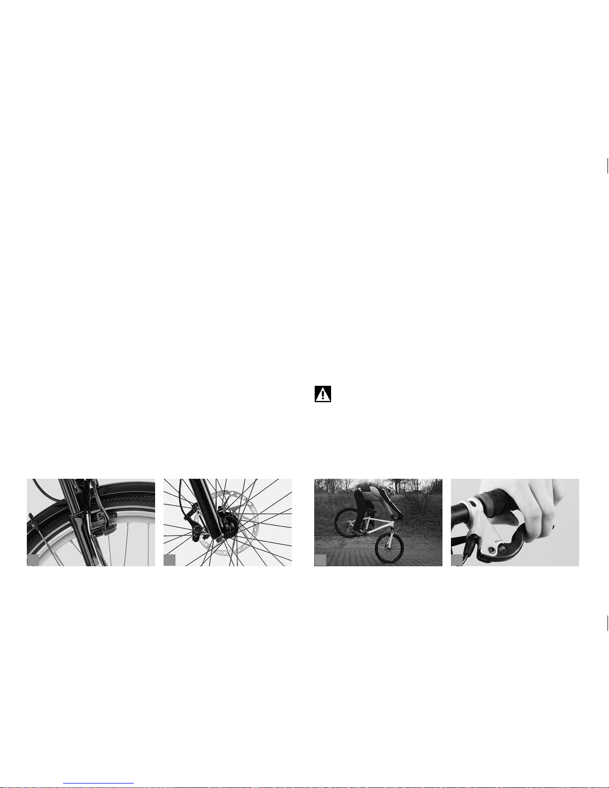
Brakes (a+b) are used for adjusting one’s speed to the surrounding
terrain and traf c. In an emergency situation, the brakes must bring the
bicycle to a halt as quickly as possible. In the process of such emergency braking, the rider’s weight shifts forward, thus reducing the load
on the rear wheel (c). The rate of deceleration is primarily limited by the
danger of the rear wheel losing contact with the ground resulting in an
overturning of the bicycle and secondly by the tyres’ grip on the road.
This problem becomes particularly acute when riding downhill. Therefore, in case of an emergency braking situation you have to try to put
your weight back as far as possible.
Actuate both brakes simultaneously and bear in mind that, due to the
weight transfer, the front brakes can generate a far better braking effect
on a surface with good grip.
The braking conditions on unpaved surfaces differ, i.e. overbraking the
front wheel can make the wheel slip away. Therefore, be sure to practise
braking on different kinds of sur face.
Wet weather reduces the braking power. Apply the brakes carefully
when riding on wet or slippery surface, as the tyres can easily slip away.
Therefore, reduce your speed when riding in such conditions.
Prolonged braking or permanent dragging of brake pads can lead to
overheating of the rims in the case of rim brakes. This can damage the
inner tube or make the tyre slip on the rim causing a sudden loss of air
which could lead to a serious accident.
With disc brakes too, prolonged braking or permanent dragging of brake
pads can lead to an overheating of the brake system. This can lead to a
reduction of the braking power or brake failure. Risk of accident!
When riding downhill, get used to braking hard and then releasing the
brake again, whenever the road surface and the situation allows for it. If
you are in doubt about the braking action, stop and let the brake system
cool down.
The assignment of brake lever to brake calliper can vary (d),
e.g. left lever acts on front brake. Make yourself familiar with
the lever-to-brake assignment or ask at a bicycle specialist
shop of your trust to change the brakes as you want them.
Page 26

22
b
c
da
Be careful while getting used to the brakes (a). Practise
emergency stops in a place free of trafc until you are comfortable controlling your bicycle. This can save you from having
accidents.
Wet weather reduces your braking power and the road grip of
the tyres. Be aware of longer stopping distances when riding in
the rain, reduce your speed and actuate the brakes carefully.
Ensure that braking surfaces are absolutely free of wax, grease
and oil. Risk of accident!
5.1.1 Brakes – How They Work and What to Do about Wear.
Actuating the hand lever on the handlebars (b) causes a brake pad to be
pressed against a brake surface, and the ensuing friction slows down the
wheel. If water, dirt or oil gets in contact with one of the braking surfaces,
this changes the coefcient of friction and deceleration is reduced. This
is why brakes respond with a slight delay and less powerfully in wet
weather.
In order to maintain their effectiveness, brakes need to be checked and
readjusted regularly.
5.2 Rim Brakes.
The friction generated by braking causes wear to the brake pads (c) as
well as to the rims. Frequent rides in the rain and dirt and over hilly terrain can accelerate wear on both braking surfaces.
Rims are provided with wear indicators, i.e. grooves (d) or circular
indentations. If the rim is worn down to the point where the grooves or
indentations are no longer visible, they need to be replaced. Once the
abrasion of the rim has reached a certain critical point, the rim may break
under the tyre pressure. This can make the wheel jam or the inner tube
burst, both of which can cause an accident!
The grooves in the brake pads are worn down by braking. See a bicycle
specialist shop of your trust and ask them to examine the remaining
thickness of the rims when you have worn through your second set of
brake pads at the latest. They have a special measuring device for determining the remaining thickness of the rims.
Wet weather reduces your braking power. Be aware of longer
stopping distances when riding in the rain!
When replacing any parts be sure to only use parts that bear
the appropriate mark and, to be on the safe side, original spare
parts. Your BMW partner will be pleased to order the respective
original spare parts for you!
Page 27

23
b
c
da
Ensure that the brake pads are absolutely free of wax, grease
and oil.
Have your rims regularly inspected and measured at a bicycle
specialist shop of your trust (a).
Brake cables that are damaged (b), e.g. frayed, should be
replaced immediately, as they can otherwise fail in a critical
moment, possibly causing an accident.
5.2.1 V-Brakes.
Common V-brake designs have two brake arms mounted separately
on either side of the rim. When actuating the brake lever, both arms are
tightened by the cable, the pads touch the rim.
5.2.1.1 Functional Check.
Check whether the brake pads are accurately aligned with the rims and
still sufciently thick. You can judge the wear of the brake pads by the
appearance of the grooves. If the pads are worn down to the bottom of
the grooves, it is time to replace them.
The brake pads must hit the rim simultaneously, rst touching it with the
front portion of their surface. At the moment of rst contact the rear por-
tion of the pads should be a millimetre away from the rim. Viewed from
the top the brake pads form a “V“ with the trough pointing to the front
(c). This V-shaped setting prevents the brakes from screeching when
applied.
The brake lever must always remain clear of the handlebars. You should
not even be able to pull them all the way to the handlebars in the event of
an emergency stop.
Only a successful passing of all these points will ensure a correctly
adjusted brake.
Adjusting the position of the brake pads relative to the rims
requires a considerable degree of skill. Replacing and adjusting
the brake pads is a job best left to a bicycle specialist shop of
your trust.
5.2.1.2 Power Modulator (d).
Some V-brakes are tted with a power modulator that acts as brake
force control during braking hereby limiting the brake force.
This device is intended to prevent overbraking and a blocking of the
front wheel.
Page 28
24
b
c
da
An inappropriately adjusted power modulator may result in
severe accidents. Ask at a bicycle specialist shop of your trust
about the system your bicycle is tted with.
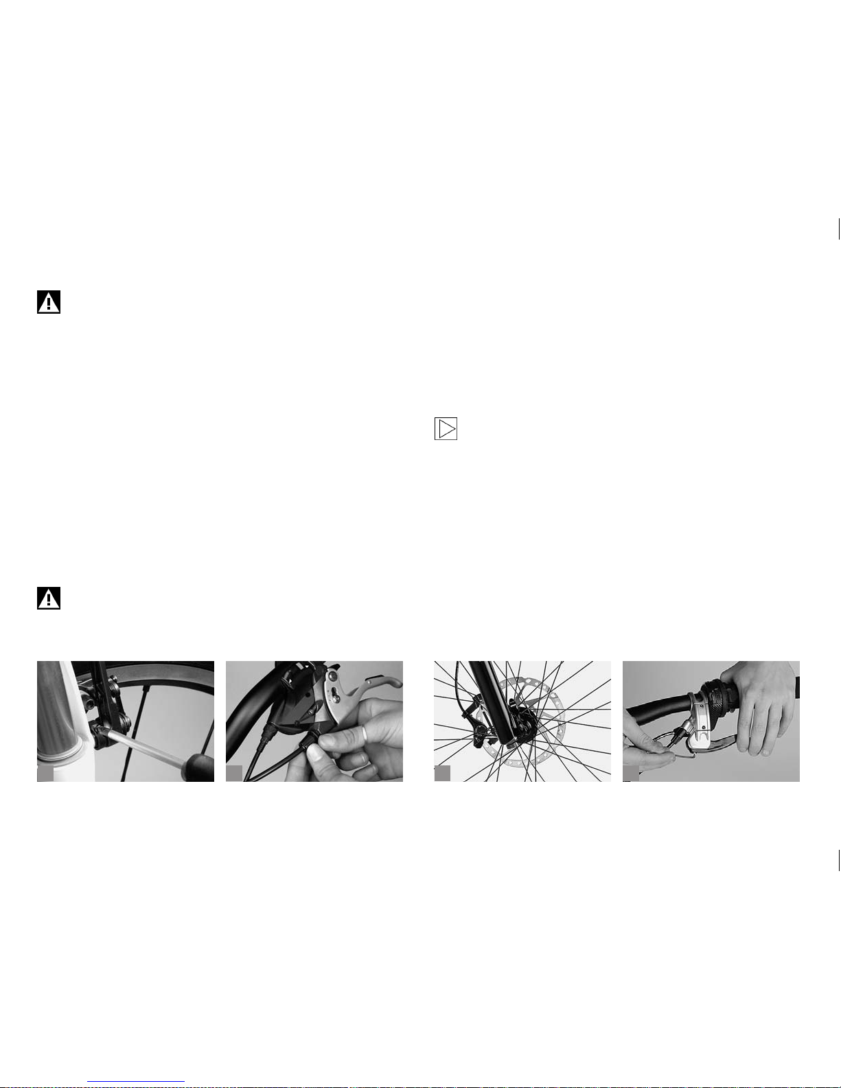
5.2.1.3 Synchronising and Readjusting.
Almost all brake designs have a bolt located next to one or both brake
callipers for adjusting the initial spring tension (a). Adjust this bolt carefully until the distance between brake pads and rim is the same on either
side.
To adjust the brakes, unscrew the knurled lock ring located at the point
where the brake cable enters the brake lever on the handlebars (b).
Unscrew the knurled, slotted adjusting bolt by a few turns. This reduces
the free travel of the brake lever. Keeping the adjusting bolt rm, tighten
the lock ring against the brake lever mount. This prevents the adjusting
bolt from coming loose by itself.
Ensure that the slot of the bolt faces neither for ward nor upward, as this
would permit water or dirt to enter.
Always test the brakes’ function while stationary after adjusting them, making sure the brake pads engage fully with the rim
when you pull them hard.
5.3 Disc Brakes.
The most striking feature of disc brakes (c) is that they combine outstanding braking power with good weather resistance. They respond a
lot faster in wet conditions than rim brakes do and achieve their normal
high braking power within a very short time. They require fairly little
maintenance and do not wear down the rims as rim brakes do. However,
they tend to be noisy when they are wet.
New brake pads have to be bedded in before they reach their
optimal braking performance. For this purpose, accelerate the
bicycle 30 to 50 times to around 30 km/h (18 mph) and bring it
to a halt each time. This procedure is nished, when the force
required at the lever for braking has stopped decreasing.
The brake levers can be adjusted to the size of your hands, allowing you
to operate them with optimal ef fectiveness. In most cases this is done
by means of a small Allen bolt located directly at the brake lever (d). You
may need to readjust the brake pads, as well. Please read the manual of
the brake manufacturer.
With mechanical disc brakes the travel of the brake lever becomes
longer as the brake pads wear down ((a) p. 25). It is therefore necessary
to readjust these brakes regularly. If you are in doubt or if you have any
questions, please contact a bicycle specialist shop of your trust!
Page 29
25
b
c
da
If your brake system works with DOT brake uid, the latter
needs to be replaced regularly according to the intervals prescribed by the manufacturer.
The manufacturers of disc brakes usually deliver their products
with detailed instructions. Be sure to read them carefully before
removing a wheel or doing any maintenance work.
Disc brakes get hot in use. For this reason do not touch the brakes directly after stopping, especially after a long downhill ride.
Do not open the brake lines. Brake uid can be very unhealthy
and damaging to the paint if it leaks out.
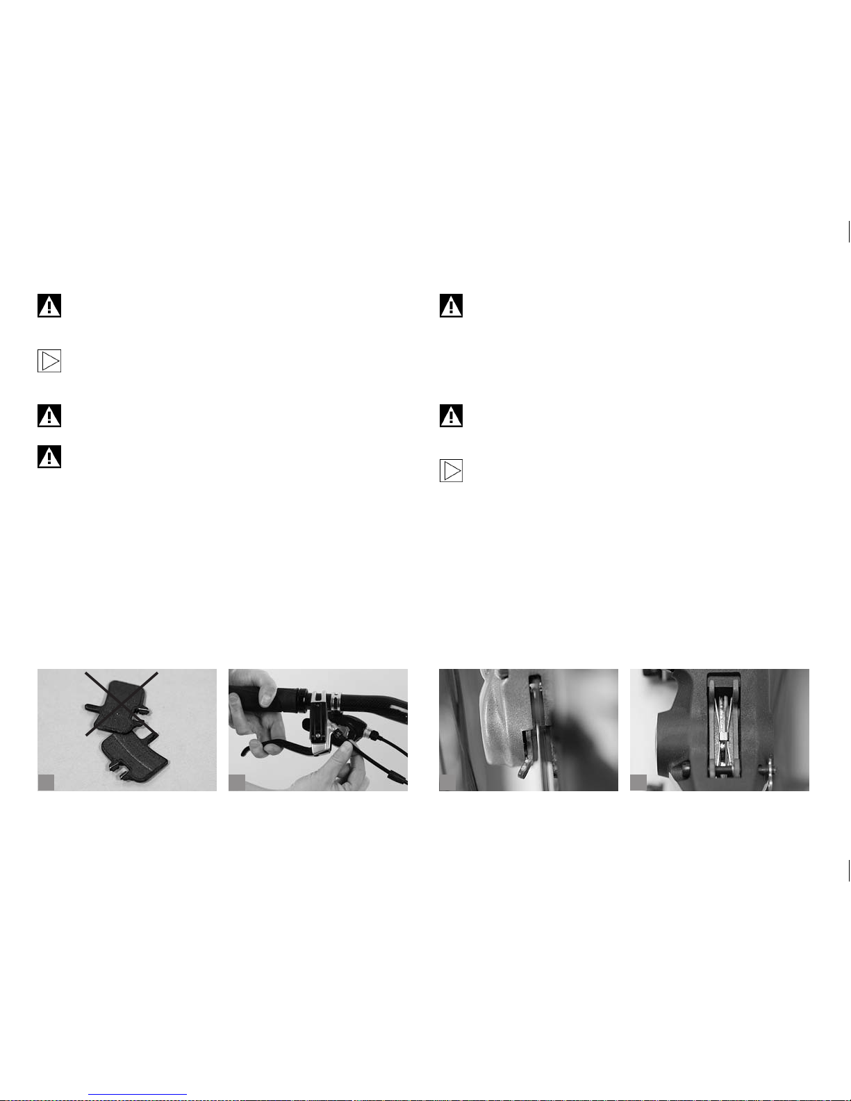
5.3.1 Checking Hydraulic Disc Brakes.
Regularly check the lines (b) and connections for leaks while pulling on
the lever. If brake uid leaks out, contact your BMW partner immediately,
as a leak can render your brakes inef fective.
Check the pads for wear by inspecting the thickness of the braking
material attached to the backing plate within the brake calliper (c) or
view through the window on the upper side of the calliper (d). If there is
approximately 1mm of material left on each brake pad, remove the pads
according to the manufacturer’s instructions, check them thoroughly
and replace them, if necessary.
Dirty brake pads and rotors can lead to drastically reduced
braking power. Therefore, make sure the brake remains free of
oil and other uids, especially when you clean your bicycle or
grease the chain. Dirty brake pads can under no circumstances
be cleaned, they must be replaced! Rotors can be cleaned
with warm water and mild soap. There are also special brake
cleaners available.
Loose connections and leaky brake lines drastically impair
braking power. If you nd leaks in the brake system or buckled
lines, contact your BMW partner immediately.
The manufacturers of hydraulic disc brakes usually deliver their
products with detailed instructions. Be sure to read them carefully before removing a wheel or doing any maintenance work.
Page 30

26
b
c
da
5.4 Roller, Drum and Back-Pedal Brakes.
These types of brakes are hardly found any more and only still common
on touring bikes (a). The brake mechanism of these brakes is fully enclosed and combined with a geared hub. Their brake pads and surfaces
are largely protected against the inuences of the weather.
5.4.1 Checking and Readjusting Hand-Operated Brakes.
Check whether the inner cables of the Bowden cables in the area of
the grips and brake itself are still in sound condition. They must not be
frayed. Damaged cables should be replaced immediately, as they can
snap. Brakes that have been adjusted at the brake lever only can lose
their braking power.
Regularly check whether you get a positive braking response before the
lever touches the handlebars (b).
To a certain extent, wear of the brake pads can be compensated directly
at the hand lever. Unscrew the union nut on the bolt through which the
cable enters the lever and then unscrew the bolt until the lever has the
desired travel.
Retighten the lock nut by taking care that the slot of the bolt does not
face upward or forward, as this would permit an unnecessarily high
amount of water or dirt to enter (c).
Now check the functioning of the brake and see to it that the brake pads
do not drag along the braking surface when you release the brake lever
and let the wheel spin.
Repeated readjustment at the brake lever makes the arm on the brake
calliper change its position. This can reduce braking power which may
be insuf cient in an extreme case! After having repeatedly readjusted
your brake on your own, ask your BMW partner or at a bicycle specialist
shop of your trust to do this delicate job.
If you intend to do any further adjustment on your brake, be sure to read
the original instructions of the brake manufacturer before you start. In
case you are in doubt, ask your BMW partner for help.
Check regularly whether the torque support is still rmly attached to the
frame or fork (d). Use a torque wrench and never exceed the maximum
tightening torque! You will nd the prescribed values in chapter “Recommended Tightening Torques”, directly on the components and/or
in the manuals of the component manufacturers.
Page 31
27
b
c
da
The risk of overheating is particularly high with closed brake systems (a).
Brake overheating occurs on prolonged (steep) downhill rides with permanent brake dragging. Brake fade is a result thereof which, in extreme
cases, may lead to brake failure. Therefore, if you notice a reduction of
the braking effect, stop and let the brake system cool down. Sometimes,
it will be enough to operate the front and rear brake in an alternating
pattern. If that will not suf ce, stop for a couple of minutes before you set
off again.
5.4.2 Checking and Readjusting Back-Pedal Brakes.
This brake is operated by pedalling backward. For maximum braking
power, step on one of the pedals in its rearmost position with the cranks
horizontal. With SRAM models braking power is increased when you
have switched to a lower gear beforehand.
With back-pedal brakes the chain tension has to be checked regularly
(b). The amount of play, midway between chainring and sprocket, should
not be more than two centimetres.
If there is any play, have the chain tightened by your BMW partner!
Check regularly whether the brake torque arm (torque support) (c) is still rmly attached to the frame or fork. Use a torque
wrench (d) and never exceed the maximum tightening torque!
You will nd the prescribed values in chapter “Recommended
Tightening Torques”, directly on the components and/or in
the manuals of the component manufacturers.
Please note that there is no rear wheel braking with a slipped
chain! Risk of accident!
Page 32
28
b
c
da
6 DRIVE SYSTEM.
The drive system includes all bicycle parts that are crucial for the
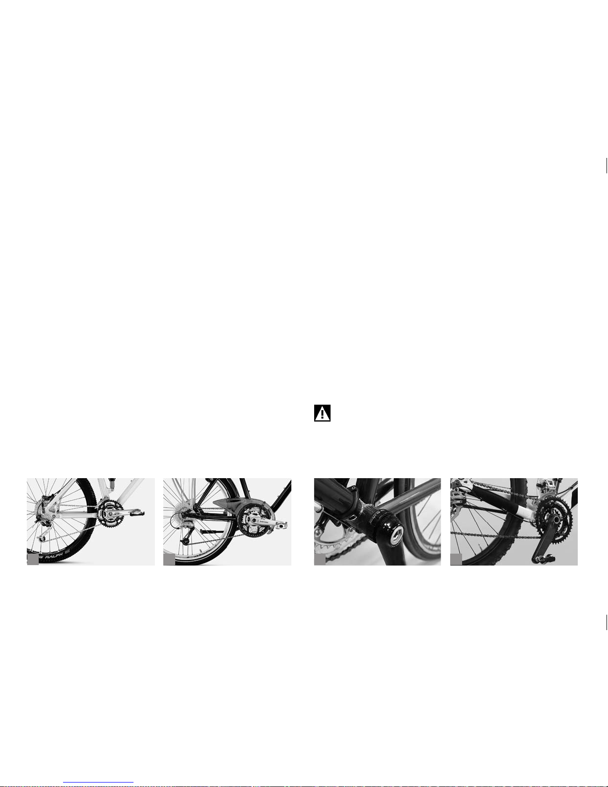
transmission of the pedalling power to the rear wheel (a+b), i.e. bottom
bracket, crankset-chainrings, pedals, sprockets and chain.
6.1 Gears.
The gears on your bicycle serve to adjust your pedalling power to the
terrain you are riding on and the desired speed. A low gear (where in the
case of derailleur gears the chain runs on the small chainring and a large
sprocket) allows you to climb steep hills with moderate pedalling force.
You must, however, pedal relatively fast. High gears (large chainring,
small sprocket) are for riding downhill. Every turn of the pedals takes you
many metres forward at correspondingly high speed.
Derailleur gears always work according to the following principle:
Large chainring – high/heavy gear – higher transmission
Small chainring – low/easy gear – lower transmission
Large sprocket – low/easy gear – lower transmission
Small sprocket – high/heavy gear – higher transmission
Normally, the shifters are mounted as follows:
Right shifter – sprockets
Left shifter – chainrings
On level ground your pedalling speed, also referred to as cadence,
should be higher than 60 strokes a minute.
6.1.1 Bottom Bracket - Crankset.
The bottom bracket (c+d) composed of ball bearings, cups, sealing
rings and spindle normally comes as a compact unit. This is to protect
the sealed cartridge bottom bracket against penetrating dirt, water or
mud. The compact bottom bracket is maintenance free and delivered
without play. Check the bottom bracket bearing in the bottom bracket
shell for play at regular intervals. The crank arms may come loose in
use over time. Regularly check whether they are rmly attached to the
spindle. Grab the crank and try to jiggle it forcefully. It must be absolutely
free of play.
If the crank arms have play, the crankset mounting may sustain
damage. Risk of breakage!
Page 33
29
b
c
da
6.2 Derailleur Gears.
Derailleur gears are currently the most effective type of power transmis-
sion on bicycles. With specially designed sprocket teeth, exible chains
and indexed lever positions, gear shifting has become very easy. Some
systems have an indicator on the handlebars showing the currently used
gear.
Modern mountain and touring bikes can have up to 27 speeds. It is not
advisable to use gears which involve an extremely oblique run of the
chain, as this reduces power transmission efciency and hastens wear of
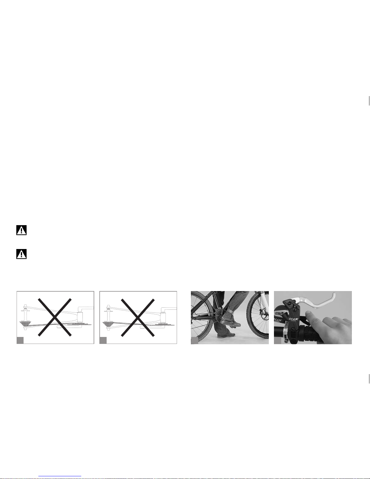
the chain. An unfavourable run of the chain is when the smallest chainring is used with one of the two or three outermost (smallest) sprockets
(a) or when the largest chainring is used with one of the inmost (largest)
sprockets (b).
Always wear straight-cut trousers or use cycle clips or the like
(c) to make sure your trousers do not get caught in the chain or
chainrings.
Shifting gears under load, i.e. while pedalling hard, can make
the chain slip. At the front derailleur the chain may even slip off
the chainrings and result in an accident.
At least the durability of the chain will be shortened considerably.
6.2.1 Derailleur Gears – How They Work and How to
Operate Them on Mountain, Cruise and Touring Bikes.
Gear shifting is initiated by actuating a shifter, a combined brake and
gear lever unit or by a short turn of the wrist with the twist grip, as the
case may be.
With Shimano Rapidre Plus shifters pressing the large shifter moves
the chain towards the larger sprockets. Pulling the small lever, located
in front of the handlebars from the rider’s viewpoint and operated with
the index nger (index nger lever) shifts the chain towards the smaller
sprockets. This means that any gear shift made by pushing the large
thumb shifter on the right produces a lower gear, while pressing the
large thumb shifter on the left moves the chain to the larger chainring,
thus producing a higher gear.
The Shimano Rapidre Plus shifters with 2-way release (d) (e.g.
XTR from model 2007 on) work according to the usual Rapidre principle (see above). The small index nger lever can be operated with the
thumb, as well. The chain runs to the small chainring or small sprockets.
You can shift several gears with one action. Pulling or pushing the shifting lever shortly results in a single gear change, pulling or pushing it long
leads to two gear shifts.
Shimano Rapid Rise derailleurs use a return spring with reversed
spring direction. Shifting with this derailleur is reversed from common
derailleurs, i.e. actuating the big shifter with the right hand leads to a
higher gear.
Page 34
30
b
c
da
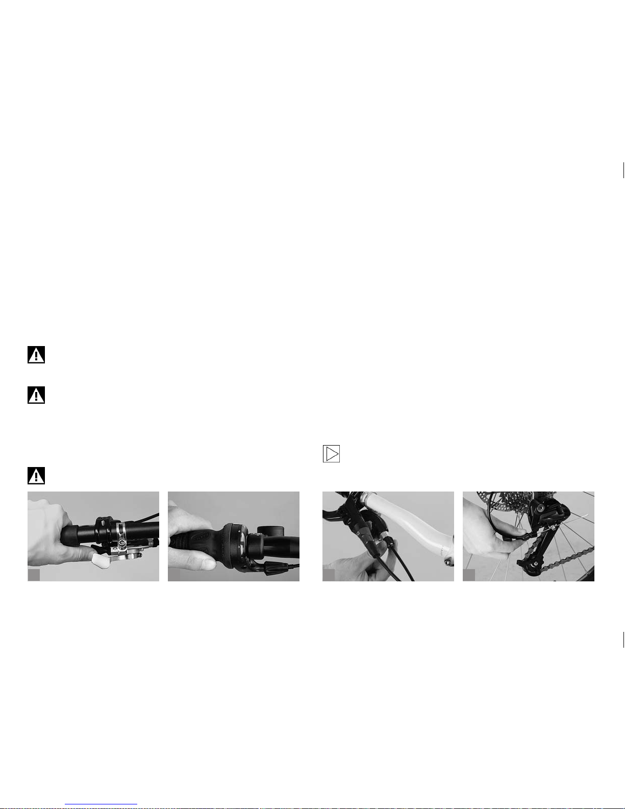
Pressing the large shifting lever of SRAM trigger shifters (a) located
under the handlebars with your thumb, shifts the chain to the bigger
chainrings and larger sprockets. The smaller shifter, also located under
the handlebars, but a bit higher than the big one, is pushed with the
thumb, too, and makes the chain move to the smaller chainrings and
smaller sprockets.
The principle of twist grips is different (b). Twisting the right-hand grip
towards you moves the chain to a larger sprocket giving you a lower
gear, while the same movement on the left produces a higher gear by
moving the chain to the larger chainrings. The shifting direction may vary
in this case, as well.
Practise switching gears in a place free of traf c until you are
familiar with the functioning of the levers or twist grips of your
bicycle.
It is therefore crucial when switching gears to continue pedalling smoothly and without too much force. Do not shift under
load, as this will shorten the durability of the chain considerably. Furthermore, this can lead to a chain-suck, i.e. the chain
can get jammed between chain stay and chainrings. Avoid
shifting gears while pedalling with force, in particular when
shifting with the front derailleur.
Avoid gears which involve an extremely oblique run of the
chain, as this will increase wear.
6.3 Checking and Readjusting Derailleur
Gears.
If you have purchased your bicycle from a BMW partner, the derailleur
gears were carefully adjusted before delivery. However, Bowden cables
may stretch a little on the rst kilometres/miles, making gear shifting
imprecise.
Adjusting the front and rear derailleur accurately is a job for an experienced mechanic.
If you want to try adjusting it yourself, be sure to read the operating instructions of the manufacturer. If you have any problems with the gears,
please contact your BMW partner or a bicycle specialist shop of your
trust!
6.3.1 Rear Derailleur.
Increase the tension of the Bowden cable by turning the adjustable
cable stop at the shifting lever (c) or the adjusting bolt through which it
runs into the rear derailleur of mountain, cruise and touring bikes (d).
Rear derailleurs are not all equipped with an adjusting bolt!
Page 35
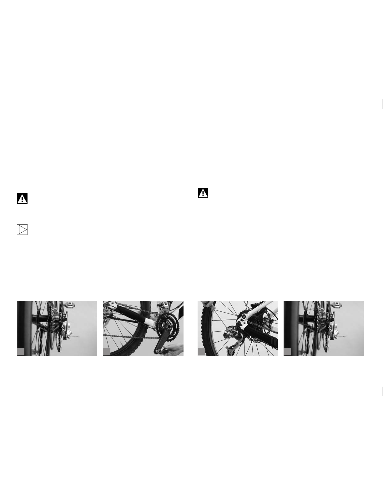
31
b d
To do so, shift to the smallest sprocket (a) and turn the clicking bolts
anticlockwise in half turns until the cable is slightly tensioned.
After tensioning the Bowden cable check whether the chain immediately
climbs onto the next larger sprocket. To nd out you either have to turn
the cranks by hand (b) or ride the bicycle and change gears.
If the chain easily climbs onto the next larger sprocket, check whether it
just as easily shifts to the small sprockets. You may need several tries.
Adjusting the front and rear derailleur accurately is a job for an
experienced mechanic. Please observe the instructions of the
gear manufacturer. If you have any problems with the gears,
contact your BMW partner.
Ask a helper to lift the rear wheel. By turning the cranks and
shifting through you can easily check the function.
6.3.2 Checking the Limit Stops.
The rear derailleur is equipped with limit screws which limit the movement range of the derailleur, thus preventing the derailleur and chain
from colliding with the spokes or the chain from dropping off the smallest sprocket. The limit screws are adjusted by your BMW partner or at
a bicycle specialist shop of your trust. They do not alter their position
during normal use.
If your bicycle has tipped over or the rear derailleur received a
blow, the rear derailleur or its mount might be bent. It is advisable to check its range of movement and readjust the limit
screws, if necessary, after such an incident or after mounting
new wheels on your bicycle (c).
Shift with the right shifting lever to the highest gear. The inner cable is
relaxed and the chain running on the smallest sprocket. Look from the
rear of the bicycle at the cassette and check whether the teeth of the
smallest sprocket and the teeth of the guide pulley are all in a perfectly
vertical line (d).
If necessar y, correct the position by means of the limit screws. The limit
screws on rear derailleurs are often marked “H” for high gear and “L” for
low gear ((a) p. 32). In this case high gear stands for high transmission
ratio, i.e. with the chain running on the smallest sprocket.
c
a
Page 36
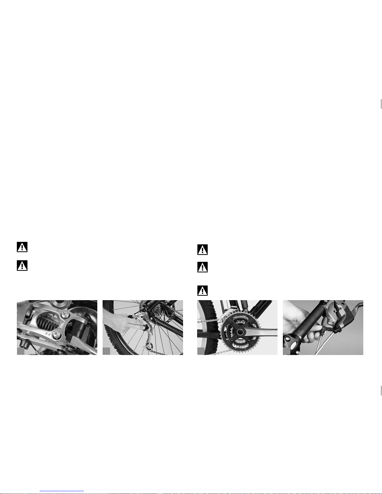
32
c
da
If the screws are not marked, you will have to nd out by trial and error.
Turn one of the screws by counting the number of turns and watch the
rear derailleur. If it does not move, you are turning the wrong one. Turn
back the counted rotations to nd its original position.
Turn the screw clockwise to shift the rear derailleur towards the wheel
and anticlockwise to shift it away from the wheel.
Continue by shifting the rear derailleur to the largest sprocket. Make
sure the rear derailleur does not collide with the spokes. When the chain
runs on the largest sprocket see whether you can shift the rear derailleur
even further by moving the shifting lever to the end of its travel. Then
press the rear derailleur further towards the spokes by hand (b). Spin
the wheel. If the derailleur cage moves towards the spokes or if the chain
begins to move beyond the largest sprocket, the derailleur movement
range needs to be limited. Turn the limit screw marked “L” clockwise
until the rear derailleur is clear of the spokes.
Be sure to go on a test ride in a place free of trafc, after adjusting the gears of your bicycle.
Improperly adjusted limit stops or a bent rear derailleur mount
can result in a severe damage to the bicycle and a rear wheel
blocking. Risk of accident!
6.3.3 Front Derailleur.
The range within which the front derailleur (c) keeps the chain on the
chainring without itself touching the chain is very small. This adjustment
is a job best left to your BMW partner or a bicycle specialist shop of your
trust.
It is often better to let the chain drag slightly on the derailleur than to risk
having the chain fall off the chainring, which would interrupt the power
train. The front derailleur, just like the rear derailleur, has limit screws
marked “H” and “L” that reduce the movement range.
As with the rear derailleur, the cable of the front derailleur is subject to
lengthening and hence to reduced precision in gear changing.
If necessar y, shift to the small chainring and increase the tension of the
Bowden cable by turning the adjusting bolt through which it passes at
the entry to the gear shifter (d) or at the frame under the down tube.
Always check after an accident whether the guide plates of the
front derailleur are still parallel to the chainrings!
Adjusting the front derailleur is a very delicate job. Improper adjustment can cause the chain to jump off, thus interrupting the
power train. Risk of accident!
Be sure to go on a test ride in a place free of trafc, after adjusting the gears of your bicycle.
b
Page 37

33
b
c
da
6.4 Multi-Speed Hubs (Internal Gear Hubs).
Two advantages of multi-speed hubs (a) are their enclosed design and
the fact that you can switch through all gears by the same lever. Besides
this, the chain lasts a lot longer than with derailleur gears, provided it is
serviced regularly.
Multi-speed or internal gear hubs from Shimano are available with a
free-wheel, i.e. the free-wheel hub is combined with a hand activated
V- or roller brake, or with an integrated drum brake, also referred to as
back-pedal brake. The latter is operated by pedalling backward. The
best braking power is achieved with the pedals on a horizontal level.
Multi-speed or internal gear hubs from SRAM are available with a
free-wheel, i.e. the free-wheel hub is combined with a hand activated
V- or drum brake, or with an integrated drum brake, also referred to as
back-pedal brake. The latter is operated by pedalling backward. The
best braking power is achieved with the pedals on a horizontal level and
in low gears.
Rohloff speedhubs are available with a free-wheel, i.e. the free-wheel
hub is combined with a hand activated rim brake (mechanical or hydraulic), or with a disc brake (mechanical or hydraulic).
6.4.1 Multi-Speed Hubs - How They Work and How to Use
Them.
Internal gear hubs are equipped with a twist grip or thumb shifter for
changing gears as well as with an indicator showing the current gear.
According to the hub manufacturer you can either continue pedalling
without load on the pedals or freewheel. Read the operating instructions
of the gear manufacturer. If you are in doubt or if you have any questions,
please contact your BMW partner! In any case, make sure changing
gears makes as little noise as possible.
SRAM twist grip shifters (b): To change gears, twist the grip, stop pedalling for a moment and do not move the pedals. SRAM I-Motion also
allows gear shifting during pedalling and in stationary.
Twist grip shifters for Shimano Nexus (c) and Rohloff hubs (d):
Continue pedalling during shifting. However, to ensure a jerk-free and
low-noise gear shifting, be sure to reduce your pedalling power.
Practise switching gears in a place free of traf c until you are
familiar with the functioning of the shift levers or twist grips of
your bicycle.
Page 38
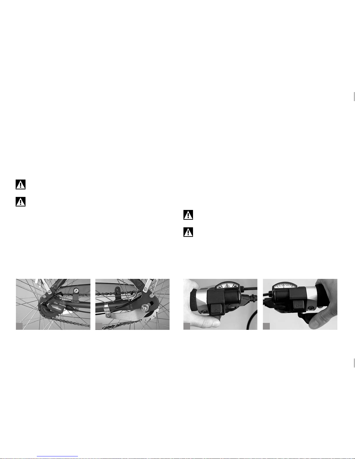
34
b
c
da
6.4.2 Checking and Readjusting.
Multi-speed hubs need not be adjusted very often. The adjusting
mechanism is mainly located at the hub (a) or at the gear box. There are
two (red) marks which have to be brought into alignment by adjusting the
cable directly at the lever or twist grip (see adjustment of the derailleur
gear). Carefully read the operating instructions of the gear manufacturer.
If you are in doubt or if you have any questions, please contact a bicycle
specialist shop of your trust!
Regularly check the reliable t of the bolted connection of the
hub and the torque arm to the frame (b).
If you have a Rohloff speed hub, be sure to make an oil change
annually or after 5,000 km (3,100 miles). If you are in doubt or
if you have any questions, please contact a bicycle specialist
shop of your trust!
6.5 Combined Derailleur/Hub Gears.
These gear systems combine the properties of both gear systems.
There is one shifter that is intended to switch the speed hub, whereas a
second shifter operates either the front derailleur of the derailleur gear or
the rear derailleur.
The Shimano Intego system (c+d) is available with a free-wheel only,
i.e. the free-wheel hub is combined with a hand activated V- or roller
brake.
The SRAM Dual Drive system is also available with a free-wheel only,
i.e. the free-wheel hub is combined with a hand activated V-, disc or
drum brake.
Make yourself familiar with your gear system and the brakes in
a place free of trafc.
The proper adjustment of the derailleur-hub gear system is a
job best left to a skilled mechanic. Before doing any adjusting,
be sure to read the instructions of the gear manufacturer.
Page 39
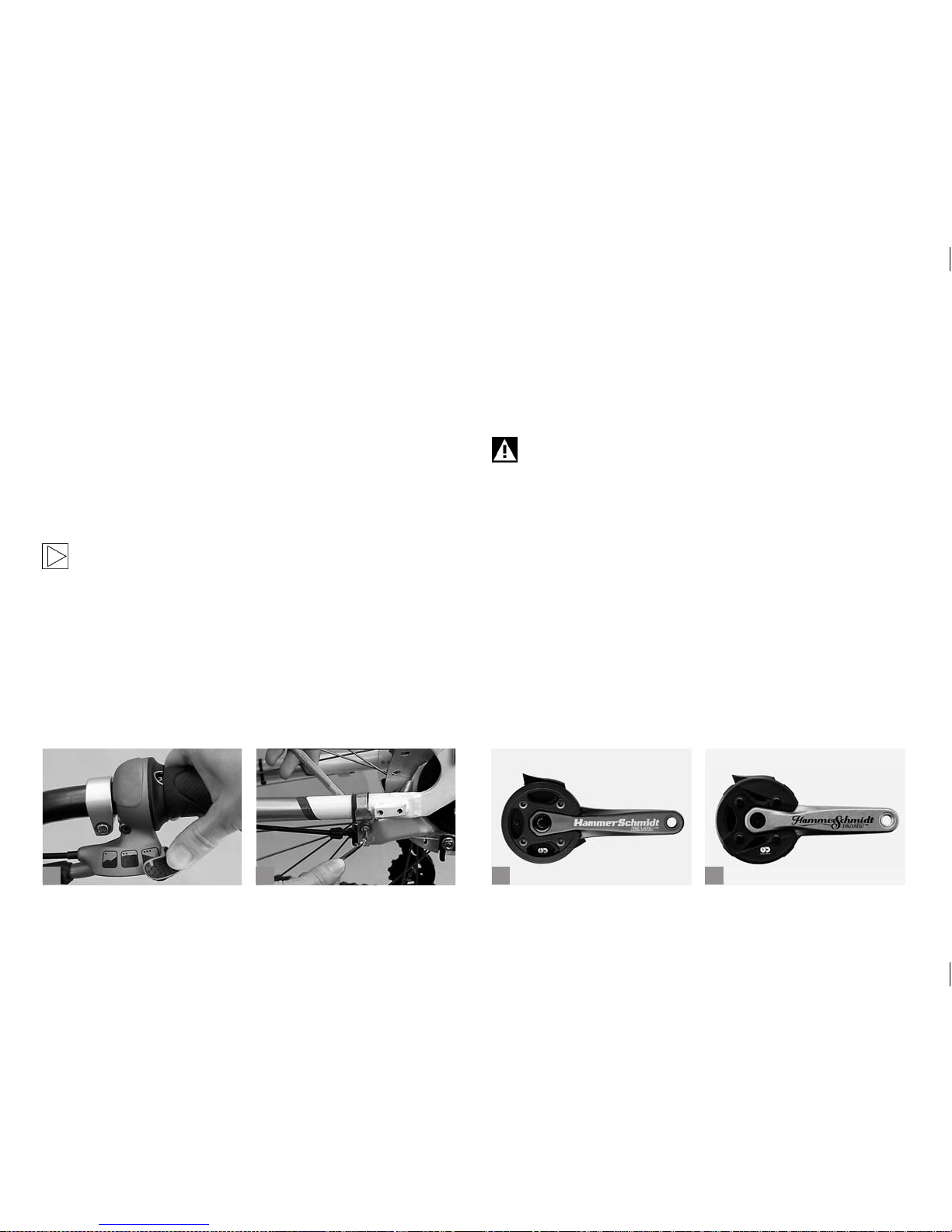
35
b
c
da
6.5.1 Combined Derailleur/Hub Gears - How They Work and
How to Use Them.
With a Shimano Intego gear system you can shift through the gears
of the speed hub with the shifter and lever on the left side.
The thumb of your right hand switches the 8-speed derailleur gear. On
both sides the big shifters are for the higher (heavier) gears.
With the SRAM Dual Drive (a) both shifters are with one hand. The
slide shifter is operated with the thumb to choose a primary transmission
for the terrain you are riding on. To change this gear, stop pedalling for a
moment without moving the pedals.
The SRAM Dual Drive 27 speed is also available with two separate trigger shifters!
The twist grip is to switch through the gears of the derailleur gear. To do
so, please continue pedalling with reduced power.
6.5.2 Readjusting.
The speed hub of the combined gear system is adjusted, as described
in chapter “Multi-Speed Hubs (Internal Gear Hubs)”, the derailleur
gears as described in chapters “Derailleur Gears” and “Rear Derail-
leur”.
Regularly check the reliable t of the bolted connection of the
hub torque arm to the frame (b).
6.6 Crank System.
The SRAM Hammerschmidt (c+d) allows two different gear ratios.
Shifting is performed with a trigger shifter on the left side. Pressing the
big thumb shifter makes for a lower gear ratio.
Page 40
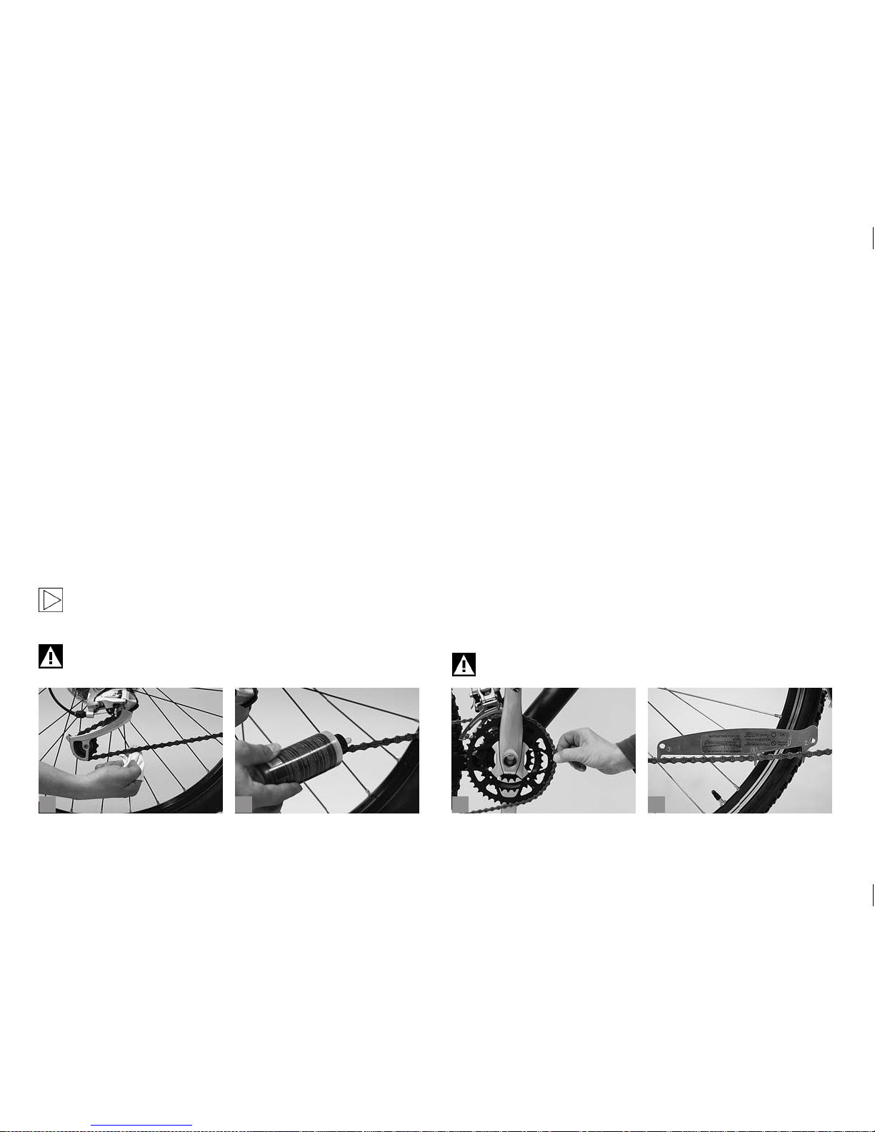
36
b
c
da
6.7 Chain.
6.7.1 Chain Maintenance.
Regular and correct lubrication of your bicycles chain makes for enjoyable riding and prolongs its service life. It is not the quantity, but the
distribution and regular application of lubricant that counts.
Clean the dirt and oil off your chain with an oily rag from time to time (a).
Special degreasers are not necessary.
Having cleaned the chain as thoroughly as possible, apply chain oil, wax
or grease to the chain links (b). To lubricate the chain, drip the lubricant
onto the rollers of the lower run of the chain while you turn the crank.
Once this is done, turn the cranks a few more times; then let the chain
rest for a few minutes so that the lubricant can disperse.
Finally wipe off excess lubricant with a rag so that it does not spatter
around during riding or can collect road dirt.
For the sake of the environment, use biodegradable lubricants
only. Bear in mind that some of the lubricant can end up on the
ground, especially in wet conditions.
Make sure the braking surfaces of the rims, the rotors and the
brake pads remain clear of lubricants, as the brakes will fail
otherwise.
6.7.2 Chain Wear.
Although the chain is one of the parts of a bicycle that wears, there are
still ways for you to prolong its service life. Make sure the chain is lubricated regularly, especially after riding in the rain. Try to only use gears
which run the chain in the straightest line between the sprockets and
chainrings and get in the habit of high cadence pedalling.
Chains of bicycles with derailleur gears are worn out after approx. 800
to 2,500 km (500 to 1,550 miles) or 40 to 125 hours of use, according to
the type of bicycle. Heavily stretched chains impair the operation of derailleur gears. Cycling with a worn-out chain also accelerates the wear of
the sprockets and chainrings. Replacing these components is relatively
expensive compared with the costs of a new chain. It is therefore advisable to check the condition of the chain at regular intervals.
To check chain wear, run the chain on the largest chainring. Take the
chain between your thumb and index nger and try to lift it off the teeth.
If you can lift it off clearly, it is stretched and should be replaced (c).
In a bicycle specialist shop of your trust they have accurate measuring
instruments for precise chain inspection (d). Replacing the chain should
ideally be left to an expert, as this requires special tools. In addition, you
need to select a chain matching your gear system.
An improperly joined or heavily worn chain can break and may
cause an accident.
Page 41
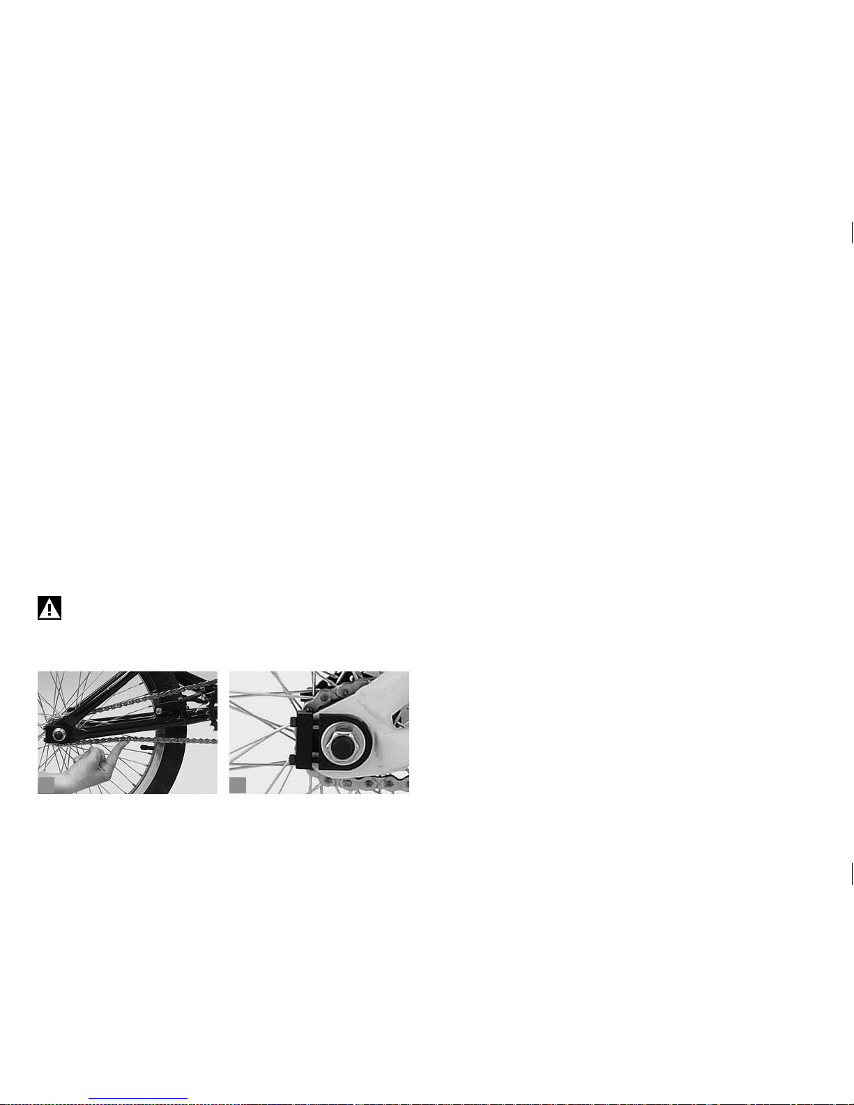
37
ba
6.7.3 Adjusting the Chain Tension of Single Speed Bicycles
and Multi-Speed Hubs.
The chain tension of single speed bicycles has to be checked and retensioned, if necessary, after approx. 1,000 km (620 miles) or 50 hours
of use. The amount of play, midway between chainring and sprocket,
should not be more than two centimetres (a).
Release the rear wheel axle bolts or nuts with an appropriate tool.
Adjust the chain tension by pulling the rear wheel to the rear or by releasing/tightening the chain tensioner. The chain tension is correct when
the amount of vertical play midway between chainring and sprocket
does not exceed two centimetres with a tightened rear wheel. Check the
vertical play in several areas. Furthermore, you should be able to rotate
the crank without resistance.
Adjust the rear wheel in the centre of the rear drop-outs by using the
chain adjuster as limit stop.
Tighten the rear wheel axle nuts with a torque wrench.
The chain adjusters (b) only serve to tension the chain and
to pre-adjust the rear wheel. They are not designed to x the
wheel in its position or to avoid any falling out.
Page 42
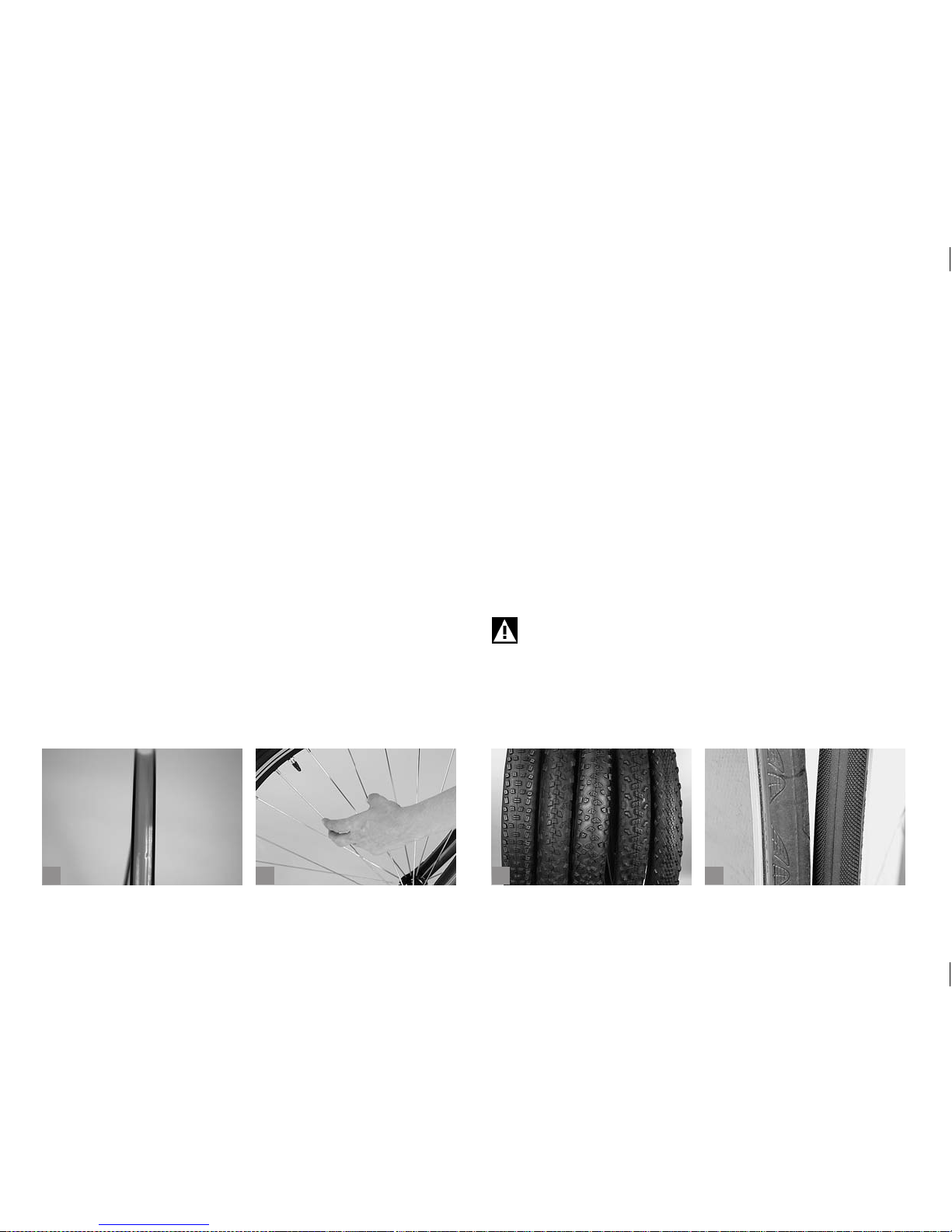
38
b
c
da
7 WHEELS AND TYRES.
The wheel consists of the hub, the spokes and the rim. The tyre is
mounted onto the rim so that it encases the inner tube. There is a rim
tape running around the trough of the rim to protect the sensitive inner
tube against the spoke nipples and the edges of the rim trough, which
are often sharp (a).
The wheels are subjected to considerable stress through the weight of
the rider and any carried baggage as well as through bumpy road surfaces and terrain. Although wheels are manufactured with great care and
delivered accurately trued, this does not prevent the spokes and nipples
from losing a little tension on the rst kilometres/miles. Therefore, ask
at a bicycle specialist shop of your trust to check and true up the wheels
after you have bedded them in over about 100 to 300 kilometres (60 to
180 miles) or 5 to 15 hours of use.
Check the wheels regularly, especially after bedding them in. It will rarely
be necessar y to tighten the spokes (b).
7.1 Tyres, Tubes, Rim Tape, Valves,
Ination Pressure.
The tyres should provide the friction needed for carrying the bicycle
forward on the riding surface. At the same time they should grant
minimum rolling friction and enhance the rider’s comfort by absorbing
small shocks. Both the rolling friction and the grip depend on the nature
of the tyre carcass, the rubber compound and the type of tyre prole.
At a bicycle specialist shop of your trust they will be pleased to help you
choose from the numerous types of tyres (c+d).
If you want to replace a tyre, you need to consider the sizing system and
the actual size of the old tyre. The latter is specied in two different units
on the side of the tyre. One of the sizes is the standardised size in millimetres which is more precise, e.g. the number sequence 52-559 means
that the tyre is 52 mm wide when fully inated and has an inner diameter
of 559 millimetres. The other size is indicated in inches (26x2.35).
Mounting a new tyre of another dimension might possibly
cause the tip of your shoe to touch the front wheel while steering. During compression of the suspension system a wheel can
get jammed, as well. Risk of accident!
Tyres have to be inated to the correct air pressure. Properly inated
tyres are also more resistant to punctures. An insufciently inated tyre
can easily get pinched (“snakebite”), when it goes over a sharp kerb.
Page 43
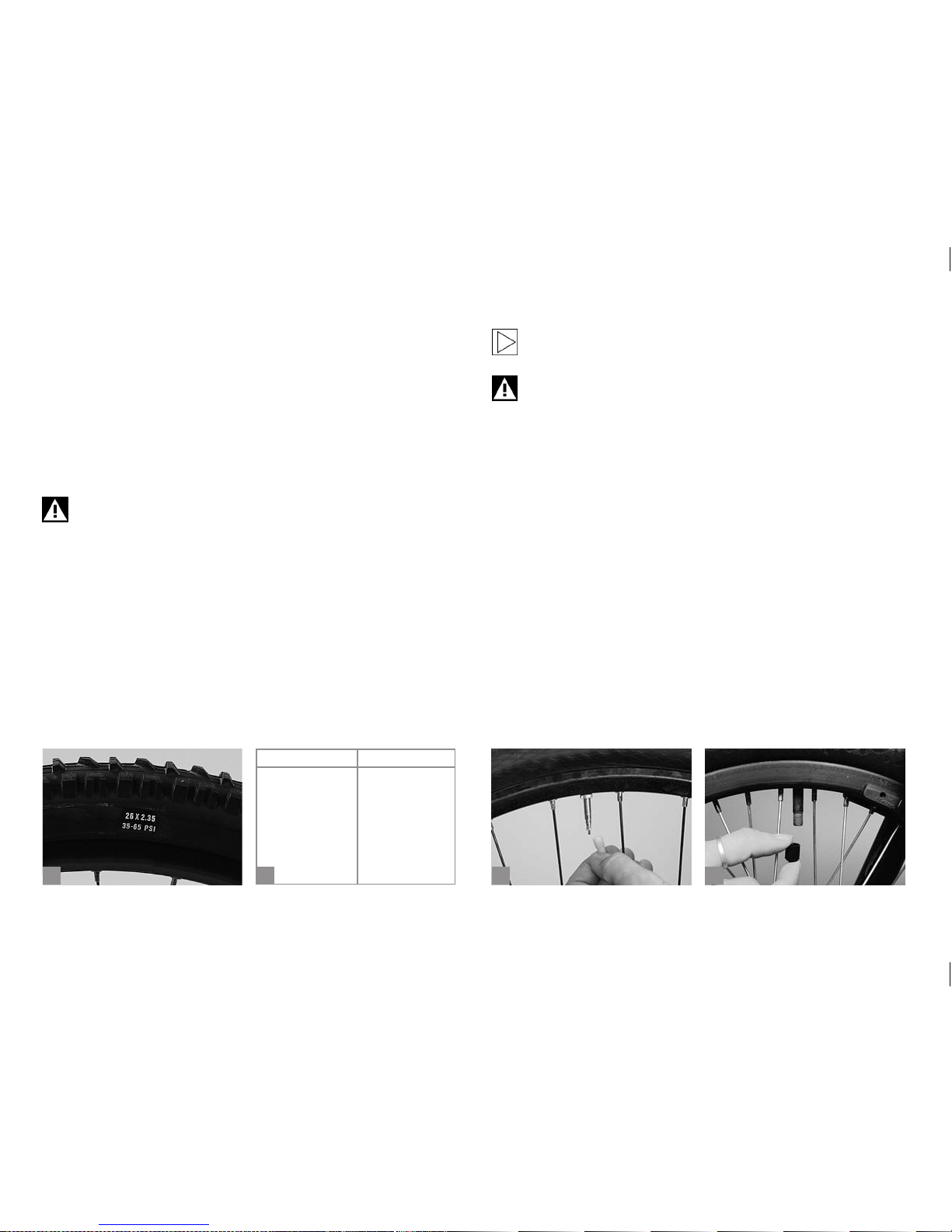
39
b
c
da
The air pressure recommended by the manufacturer is given on the side
of the tyre or on the type label (a). The lower of the two pressure specications makes for better cushioning for lightweight riders and is therefore best for cycling on a rough surface. Rolling resistance decreases
with growing pressure, but so does comfort. Highly inated tyres are
therefore most suitable for heavy riders and for riding on tarred roads.
Ination pressure is often given in the old system of units, i.e. in psi
(pounds per square inch). The table below (b) gives the most common
pressure values in terms of both systems.
Tyres allowing an ination pressure of 5 bars or more have to
be mounted on hook bead rims, identiable by the designation
“C“. If you are in doubt or if you have any questions, please
contact a bicycle specialist shop of your trust!
The tyre and rim alone are not able to hold the air. Therefore, an inner
tube has to be placed inside the tyre to retain the air pressure.
This does not apply to tubeless wheel/tyre systems (tubeless/USTtyres/NoTubes systems). In this case, the rim and the tyre hold the air
without inner tube. For more information read the chapter on UST tyres
further below or the respective instructions, before doing any work on
such kind of tyres.
If you have a bicycle with tubeless tyres, please read the instructions of the tyre/rim manufacturer.
Treat your tyres well, in particular avoid sharp edges where
possible! Never inate your tyres beyond the maximum permissible pressure, otherwise one of them might burst or come off
the rim during the ride. Risk of accident!
There are three valve types in general use on today’s bicycles:
1. Sclaverand or Presta valves (c): This type is nowadays used on
almost all types of bicycles. It is designed to withstand extremely high
pressures.
2. Schrader or car valve (d): This is an adapted car tyre valve which is
mainly used on mountain bikes.
3. Dunlop or Woods valve, the usual valve.
These three valve types are tted with a plastic cap to protect them from
dirt.
The car valve can be inated with a suitable pump directly after removing
the protective cap.
With Presta valves you rst have to undo the small knurled nut a little and
depress it carefully until air starts to escape ((a) p. 40). Check the nut is
tightened and seated in its stem, otherwise air may slowly leak out.
psi bar kPa psi bar k Pa
30 2.1 210
90
6.2 620
40 2.8 280 100 6.9 690
50 3.5 350 110 7.6 760
60 4.1 410 120 8.3 830
70 4.8 480 130 9.0 900
80 5.5 550 140 9.7 970
Page 44
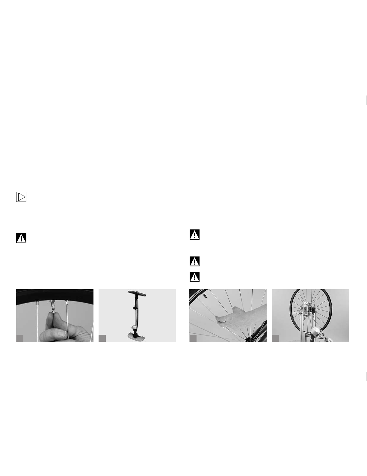
40
b
c
da
Tyres with car valves can conveniently be inated at car lling stations
with a compressed air dispenser. The same applies to Presta valves
tted with a special adapter. A compressed air dispenser must be used
very carefully as you may other wise overinate the tyre and make it
burst. To let out air, press the needle in the centre of the car valve or the
knurled nut of the Presta valve using e.g. a spanner/key.
Hand pumps are often unsuitable for inating tyres to high pressures. A
better choice is a foot-operated or a track pump equipped with a pressure gauge (b).
Always ride your bicycle with the prescribed tyre pressure and
check the pressure at regular intervals, at least once a week.
Replace tyres with a worn tread or with brittle or frayed sides. Dampness
and dirt penetrating the tyre can cause damage to its inner structure.
The inner tube might burst. Risk of accident!
Obser ve the maximum pressure value of the rim. The pressure
is dependent on the tyre width! You will nd the values in the
enclosed manuals of the rim manufacturers.
7.2 Rim Trueness, Spoke Tension.
To obtain true running of the wheel, the tension exerted by the spokes
has to be distributed evenly around the rim (c). If the tension of a single
spoke changes, e.g. as a result of riding fast over a kerb or of a loose
nipple, the tensile forces acting on the rim become unbalanced and the
wheel will no longer run true. The functioning of your bicycle may even
be impaired before you notice the wobbling appearance of a wheel that
has gone out of true.
With rim brakes the sides of the rims also serve as braking surfaces. An
untrue wheel can impair your braking power. It is therefore advisable to
check the wheels for trueness from time to time. For this purpose lift the
wheel off the ground and spin it with your hand. Watch the gap between
the rim and the brake pads. If the gap varies by more than a millimetre,
you should ask at a bicycle specialist shop of your trust to true up the
wheel (d).
Do not ride with untrue wheels. In the case of extreme side-to-
side wobbles, the brake pads of rim brakes can miss the rim
and get caught in the spokes! This normally instantly jams the
wheel and throws you off your bicycle.
Loose spokes must be tightened at once. Otherwise the load
on the other spokes and the rim will increase.
Truing (retruing) wheels is a difcult job which you should
denitely leave to a mechanic of a bicycle specialist shop of
your trust!
Page 45
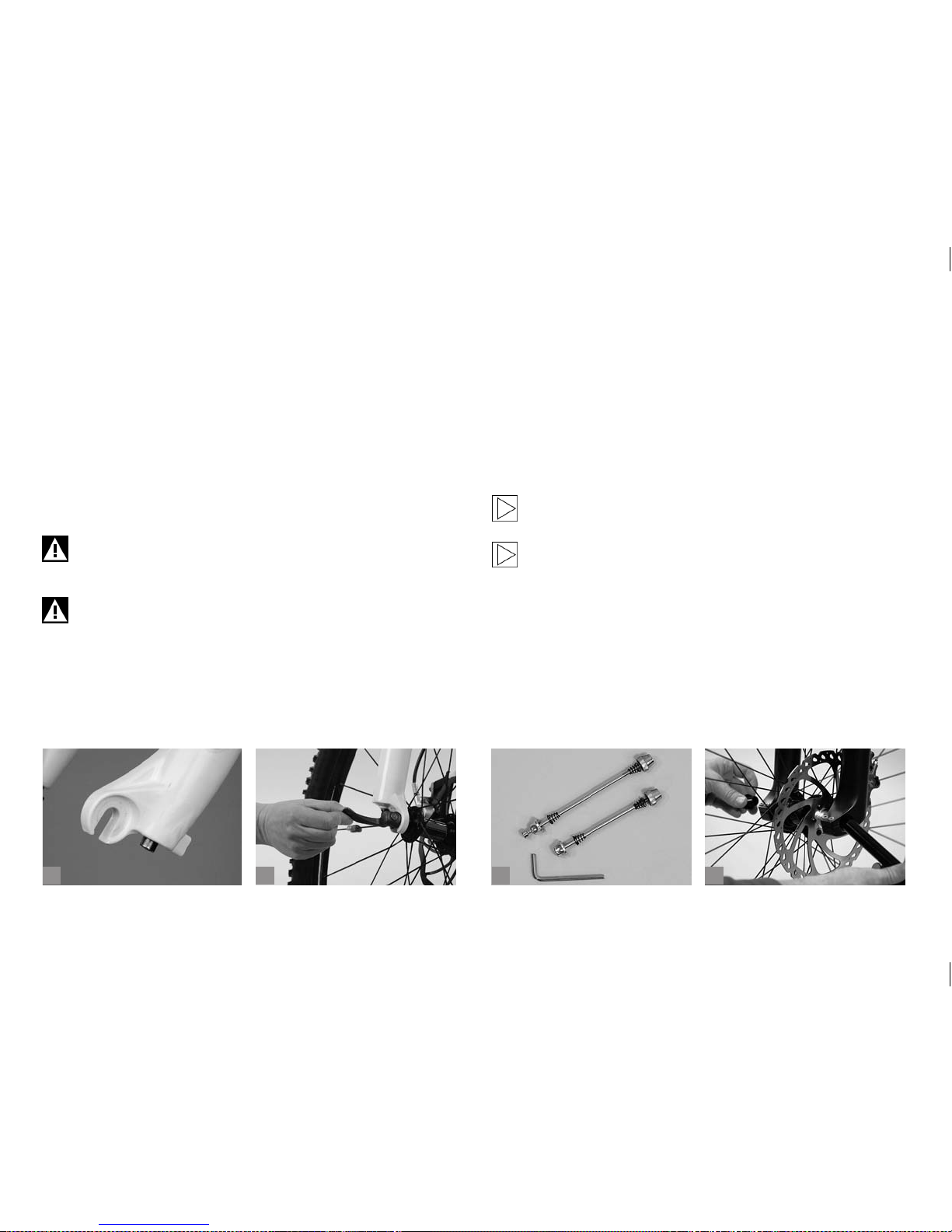
41
b
c
da
7.3 Wheel Fastening with Quick-Releases.
The wheels are attached to the frame at the hub axles. Each axle is
clamped tight in the drop-outs (a) by means of a quick-release.
Quick-releases require no tools at all. Just release the lever (b), unscrew
it a few turns, if necessary, and take out the wheel (see chapter “How to
Use Quick-Releases and Thru Axles“).
However, a thief will nd this just as easy to do! As an anti-theft measure
you can replace the quick-releases by special locks. They can only be
opened and closed with a special, coded key or an Allen key (c).
Never ride a bicycle without having rst checked whether the
wheels are securely fastened! A wheel that comes loose whilst
riding will throw you off your bicycle!
If your bicycle is equipped with quick-releases, be sure to lock
the frame to an immovable object together with the wheels
when you leave it outside.
7.4 Wheel Fastening with Thru Axle
Systems.
There is a wide range of different thru axle systems (d) currently available. Some systems are tightened with quick-releases. Other systems
may require special tools for assembly or disassembly.
Check the fastening after one to two hours in use and then ever y 20
hours of use.
For more information read chapter “How to Use Quick-Releases and Thru Axles”.
Always obser ve the enclosed instructions of the fork manufacturer.
Page 46
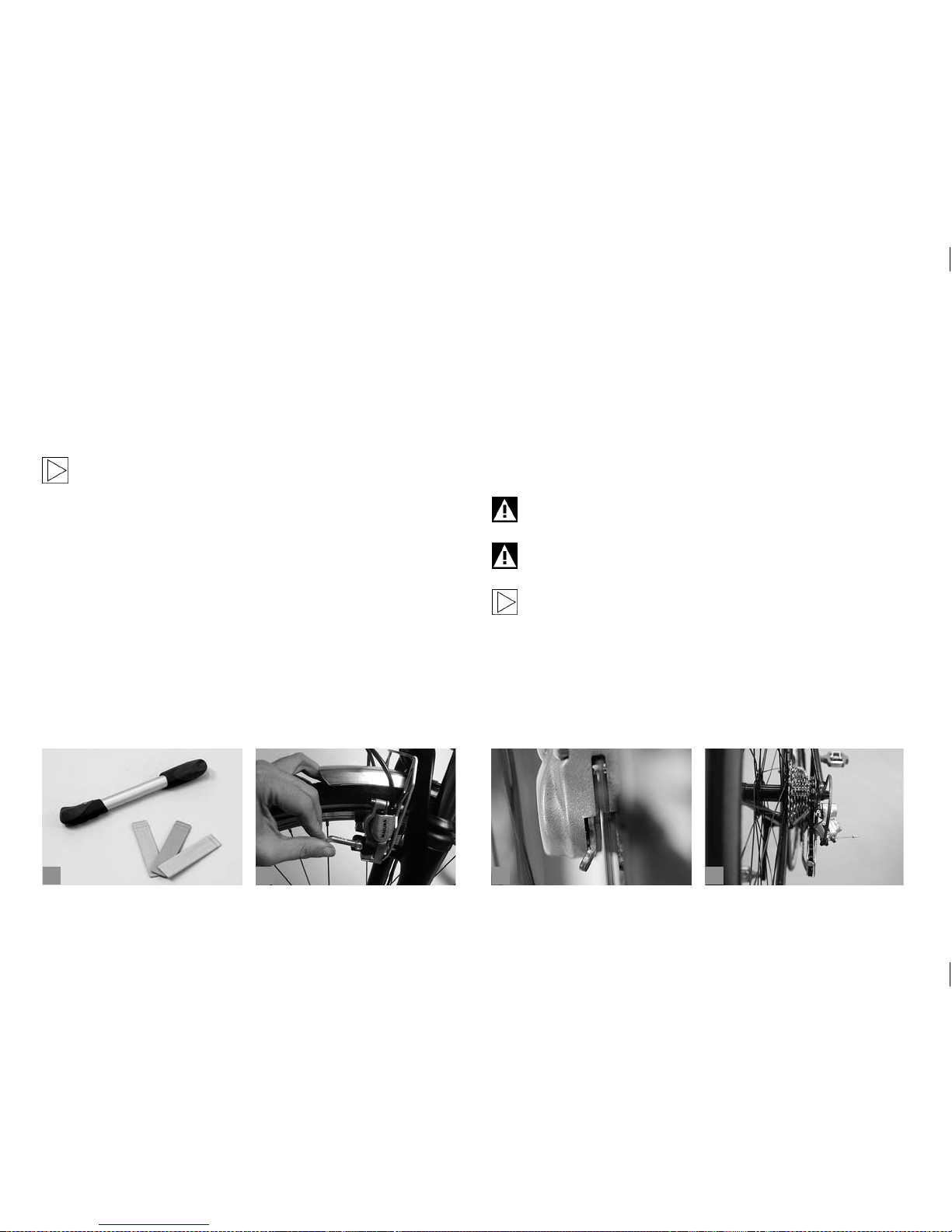
42
b
c
da
7.5 Puncture.
Flat tyres are the most common cause of puncture during cycling.
However, as long as you have the necessary tools for changing tyres and
tubes and a spare tube or a repair kit, this need not mean the end of your
cycle ride. For bicycles with quick-releases all you need in addition are
two tyre levers and a pump (a).
Be sure to read chapters “Wheel Mounting” and“How to Use
Quick-Releases and Thru Axles” before wheel removal. If
you are in doubt or if you have any questions, please contact a
bicycle specialist shop of your trust!
7.5.1 Wheel Removal.
Step one with the brakes of mountain, cruise and touring bikes
If your bicycle has rim brakes (cantilever or V-brakes) you rst have to
unhook the brake cable from the brake arm. To do this, grip the brake
with one hand and press the brake pads and arms together. In this position it should be easy to disengage the usually barrel shaped nipple or, in
the case of V-brakes, the outer cable.
If your bicycle has hydraulic rim brakes (b) from Magura, unlock its
quick-release on one side of the brake and take it off the mounting bolt.
If your bicycle has drum or roller brakes and internal gear hubs,
loosen the torque arm supporting the drive and braking force on the
frame. Furthermore, you need to disconnect the shifting cables and the
clickbox respectively before removing the wheel.
If you have hydraulic disc brakes, you should rst check the exact
position and condition of the brake pads and/or wear indicators (ear or
nose-shaped metal protrusions) (c). In this way you will be able to tell after the removal whether the brake pads are still in their correct position.
Read the brake manufacturer’s instructions!
Do not pull the (disc) brake lever with a removed wheel and
make sure to mount the safety locks when removing the wheel.
Rotors can become hot, so let them cool down before removing
a wheel.
Please read the operating instructions of the brake and the
gear manufacturer.
If you have derailleur gears, you should shift the chain to the smallest
sprocket before removing the rear wheel (d). This shifts the rear derailleur right to the outside where it does not interfere with the removal of
the wheel.
Page 47
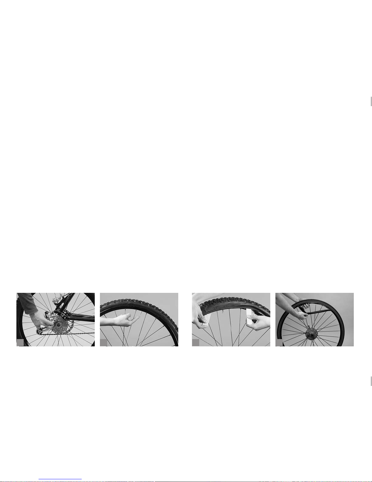
43
b
c
da
Open the quick-release, as described in chapter “How to Use QuickReleases and Thru Axles”.
If you cannot remove the wheel after releasing the lever, this is due to
the drop-out safety tabs. They come as metal catches which engage
with recesses in the drop outs. Just release the quick-release adjusting
nut a little and slip the wheel past the tabs.
You will nd it easier to remove the rear wheel, when you pull the rear
derailleur slightly backwards (a). Lift the bicycle off the ground and give
the wheel a gentle tap with your hand so that it drops out.
If you have a bicycle with thru axles, please read chapter “How to Use
Quick-Releases and Thru Axles”.
In case you are in doubt about how to handle thru axles, please contact a
bicycle specialist shop of your trust!
In the case of combined derailleur and internal gear hubs the click-
box must also be removed rst before you can dismount the rear wheel,
as is the case with typical derailleur gear rear wheels.
7.5.2 Tyre Removal (Clincher, Folding Tyres).
Remove the cap and the fastening nut off the valve and deate the tyre
completely (b). Press the tyre from the sides towards the centre of the
rim. You will nd it easier to remove the tyre, if you do this around its
entire circumference.
Apply a plastic tyre lever to one bead of the tyre about 5 cm beside the
valve and lever the tyre out of the rim in this area (c). Hold the tyre lever
tight in its position. Slip the second tyre lever between rim and tyre at a
distance of about ten centimetres on the other side of the valve and lever
the next portion of the bead over the edge of the rim.
After levering a part of the tyre bead over the edge of the rim you should
normally be able to slip off the whole tyre on one side by moving the tyre
lever around the whole circumference. Now you can remove the inner
tube (d). See to it that the valve does not get caught, as this can damage
the inner tube. If necessary you can remove the whole tyre by pulling
the other tyre bead off the rim. Repair the puncture according to the
instructions of the repair kit manufacturer or replace the inner tube by a
new one.
Page 48
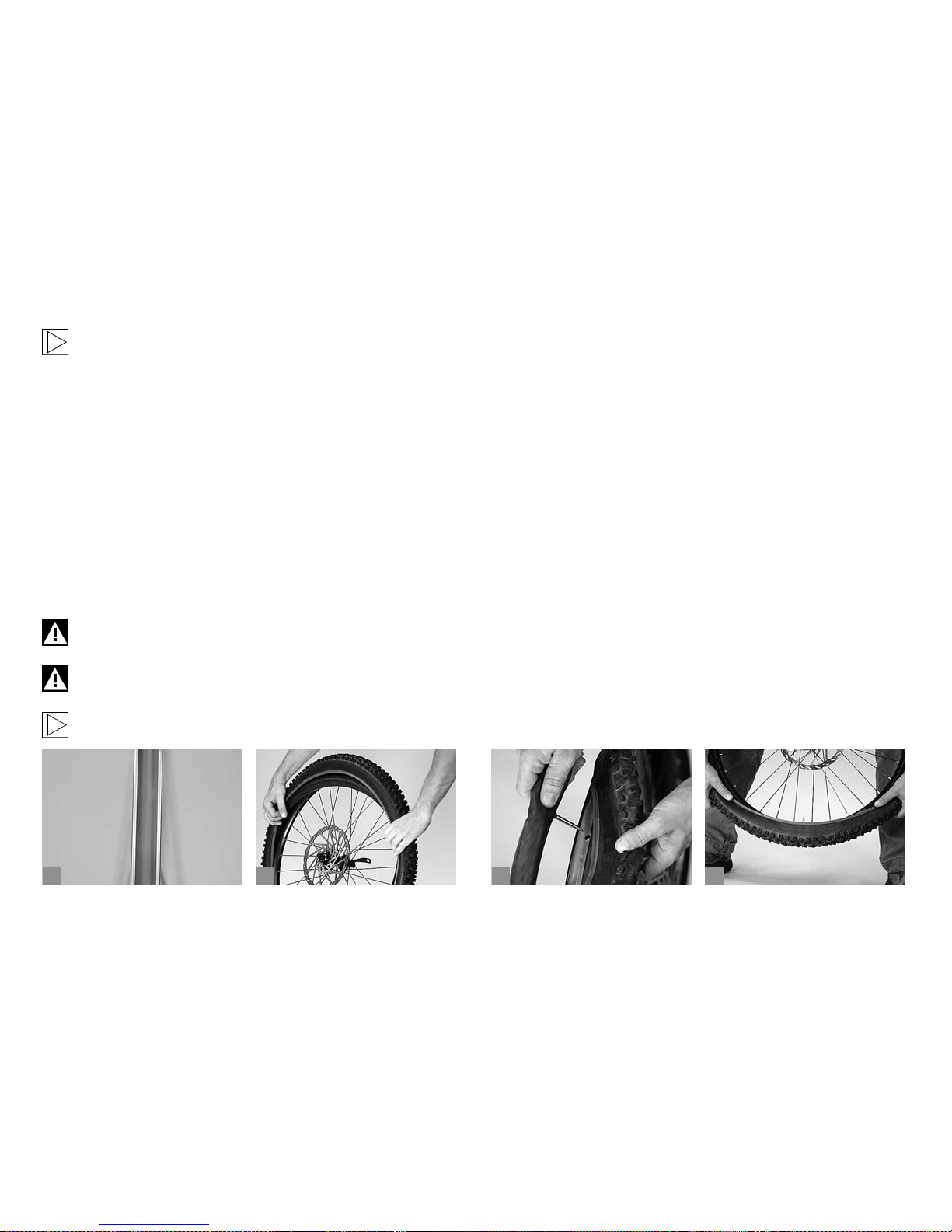
44
b
c
da
If you have a puncture whilst riding, do not pull the whole inner
tube out of the tyre. Leave the valve sticking through the rim,
inate the inner tube and bring it close to your ear. In most
cases you can hear the air coming out. At home you can help
yourself with a bucket of water where you can locate the hole
by the bubbles. When you have found the hole, look for the cor-
responding place on the tyre and check it. Often, you will nd
a foreign body sticking in the tyre, which ought to be removed.
Otherwise another puncture can occur.
When you have removed the tyre, you should also check the rim tape
(a). It should lie squarely in the trough of the rim, covering all spoke nip-
ples, and should not be torn anywhere or brittle. In the case of double
wall rims the tape must cover the entire rim base, but it should not be so
broad as to stand up along the inside edges of the rim trough. Rim tapes
for this type of rim should only be made of textile or durable plastic. If
you are in doubt or if you have any questions, please contact a bicycle
specialist shop of your trust!
Replace spoilt rim tapes immediately.
If the fabric of the tyre is destroyed by the perforating object,
replace the tyre as a precaution.
Dismounting a Rohloff rear wheel requires special handling.
Please follow the enclosed Rohlof f instructions!
7.5.3 Tyre Mounting (Clincher, Folding Tyres).
When mounting a tyre make sure no foreign matter, such as dirt or sand,
gets inside the tyre and you do not damage the inner tube in the process.
Slip one bead of the tyre onto the rim (b). Using your thumbs, press the
bead over the edge of the rim and then around the entire circumference.
This should normally be possible without using tools.
Stick the valve of the tube through the hole in the rim (c). Inate the inner
tube slightly so that it becomes round and push it into the tyre all the way
round. Make sure not to leave any folds in the tube.
To nish mounting the tyre, start at the opposite side of the valve. Using
your thumbs, press as much of the second bead of the tyre over the
edge of the rim as you can (d). Make sure the inner tube does not get
pinched and squashed between tyre and rim. You can prevent this by
pushing the inner tube into the hollow of the tyre with a nger as you
work along.
Work the tyre into the rim, approaching the valve symmetrically from
both sides. Towards the end, you will have to pull the tyre vigorously
downwards to make the already mounted portion of the tyre slip towards
the deepest part of the rim trough. This will ease the job noticeably on
the last centimetres.
Page 49
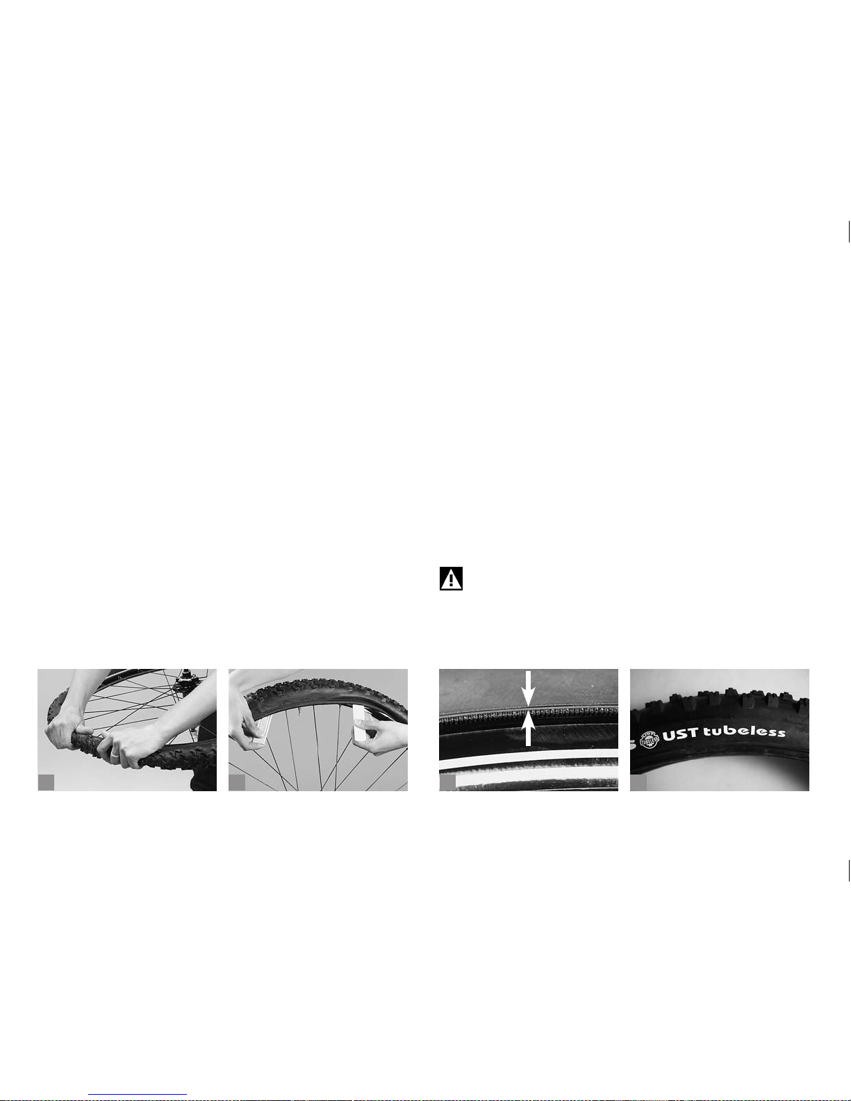
45
b
c
da
Before tting the tyre completely on the rim check again whether the
inner tube lies properly inside the tyre and press the last stretch of tyre
over the edge of the rim using the balls of your thumbs (a).
If this does not work, you will have to use the tyre levers (b). Make sure
the blunt ends point towards the inner tube and the inner tube does not
get damaged.
Push the valve a little into the tyre so that the inner tube does not get
caught between the rim and the tyre beads. Check whether the valve
stands upright. If not, dismount one bead again and reposition the inner tube. To make sure the inner tube does not get pinched between
rim and bead, inate the tyre a little and then move it sideways back
and forth between the sides of the rim. While doing this you can check
whether the rim tape has shifted.
Inate the inner tube to the desired pressure. The maximum pressure is
indicated on the side of the tyre.
Check the seating of the tyre by means of the “witness line” running
around the side of the tyre just above the edge of the rim (c). The distance between the line and the edge of the rim should be even around
the entire circumference of the tyre.
7.5.4 Removal of Tubeless Tyres (d).
Deate the tyre completely. Press the tyre from the sides towards the
centre of the rim, until both beads lie slack in the centre of the rim. Start
removing the tyre at the point opposite the valve and lift one tyre bead
with your ngers over the edge of the rim. Do not use tyre levers! Slip
the entire tyre bead over the rim. Then pull the other bead off the rim, as
well.
7.5.5 Repair of Tubeless Tyres.
In the event of a puncture tubeless tyres also work with an inserted inner
tube. First remove the perforating object, as far as available, from the
tyre and remove the valve from the rim. Insert a slightly inated new inner tube into the tyre. Mount the tyre as described below and make sure
it is properly seated in the rim and inated to the specied pressure.
Tubeless tyres can be sealed on the inside with a conventional repair
patch, as well. Observe the instructions of the repair kit manufacturer.
Improper mounting can lead to malfunctioning or even result in
brake failure. Therefore, be sure to follow the instructions of the
manufacturer included with the delivery.
Page 50
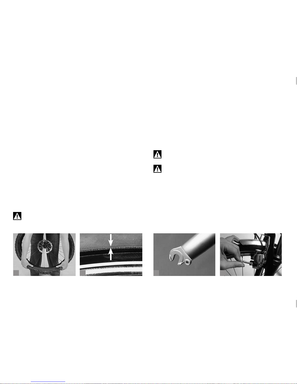
46
b
c
da
7.5.6 Mounting Tubeless Tyres.
Before mounting a tyre make sure it is free of dirt and lubricant on the
inside and around the beads. Do not use tyre levers!
To prevent any damage, wet both beads all around with soapy water or
with tyre mounting lubricant and press the tyre with your hands onto the
rim.
Press one bead over its entire circumference over one edge of the rim
and then the second tyre bead (a). Centre the tyre in the rim. Make sure
the tyre is properly seated in the rim base and the beads lie symmetri-
cally on either side of the valve. Inate the tyre with a compressor or a
CO2-cartridge to the maximum permissible pressure so that it can get
seated on the rim. The permissible pressure is usually specied on the
side of the tyre.
Check whether the tyre is properly seated by inspecting the ne witness
line (b) just above the rim edge. This line should be even to the rim
all around the tyre. Starting from the maximum tyre pressure you can
now reduce the pressure through the valve to suit your needs. Please
observe the recommended tyre pressure range.
Tubeless tyres must be mounted on UST rims or UST wheels
(Mavic and other manufacturers) only.
7.5.7 Wheel Mounting.
Mounting the wheel is done in the reverse order of dismounting. Make
sure the wheel is correctly seated in the drop-outs (c) and accurately
centred between the fork legs or the seat and chain stays.
Make sure the quick-release, the drop-out safety tabs and the thru axle,
if available, are correctly seated. For more information see chapter “How
to Use Quick-Releases and Thru Axles”.
If you have rim brakes, make sure you hook the brake cable
back up immediately!
Mount the hydraulic rim brakes and close its quick-release immediately after xing the wheel (d)! Make sure the brake pads
touch the rim and not the tyre or the spokes.
If you have disc brakes, check before mounting the wheel whether the
brake pads rest snugly in their seats in the brake calliper body. The
gaps between the brake pads and the wheel should be parallel and the
wear indicators in their correct position. Make sure you guide the rotor
between the brake pads carefully.
Page 51
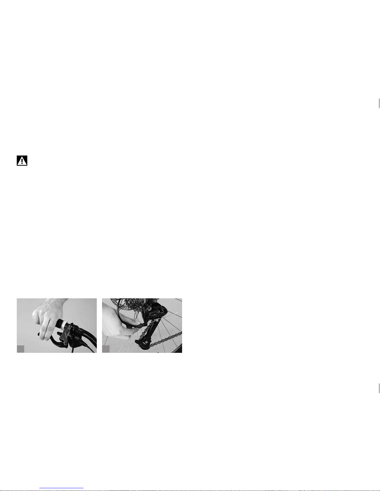
47
ba
After mounting the wheel and tightening the quick-release pull the brake
lever (a) and spin the wheel. The rotor should not drag on the brake
caliper or on the brake pads.
Before riding again check that you have not let any grease or
other lubricants get on the brake surfaces (b) or rotor while
mounting the wheel.
Check whether the brake pads hit the rotors or braking surfaces of the
rims. Make sure the wheel is properly seated and rmly xed in the dropouts. Always do a brake test as described in chapter “Before Every
Ride“!
Page 52
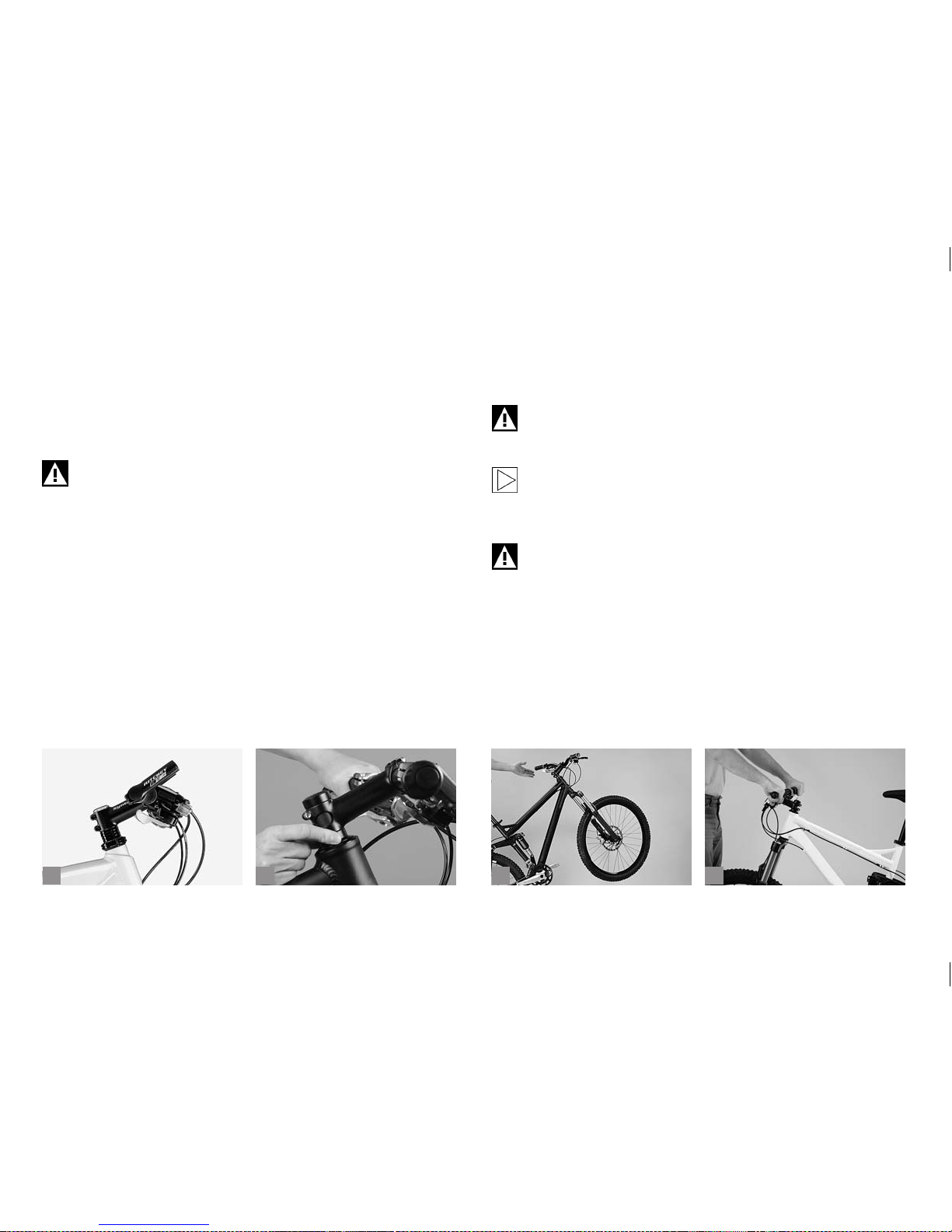
48
b
c
da
8 HEADSET.
The headset (a) connects the fork to the frame, but allows it to move
freely. It must turn with virtually no resistance, if the bicycle is to run
straight, stabilising itself as it travels. Shocks caused by uneven road
surfaces expose the headset to considerable levels of stress. In this way
it can become loose and go out of correct adjustment.
Riding the bicycle with a loose headset increases the stress on
fork and bearings. The fork can break and throw you off your
bicycle!
8.1 Checking the Headset.
Check the headset for play by placing your ngers around the upper
headset cup (b).
Bring your weight to bear on the saddle, pull the front brakes with your
other hand and push the bicycle rmly back and forth with the wheel
remaining on the ground. If the bearing has play, you will feel the upper
headset cup moving relative to the upper bearing cap - visible as a small
gap between the cup and the cap.
To check whether the bearing runs smoothly, lift the frame up until the
front wheel no longer touches the ground. The handlebars should turn
from far left to far right without feeling roughness or tightness at any
point. Turning the bars should require only a little tap on the grips (c).
Adjusting the headset requires a certain amount of experience
and should therefore be left to your BMW partner or a bicycle
specialist shop of your trust.
If you want to adjust conventional headsets you will need special tools. If you nevertheless want to tr y adjusting it yourself,
please read the operating instructions of the manufacturer
carefully before you do!
Check the secure seat of the stem after having adjusted the
bearings, by holding the front wheel between your knees and
trying to twist the handlebars relative to the front wheel (d).
Otherwise, a loose stem can throw you off your bicycle.
Page 53
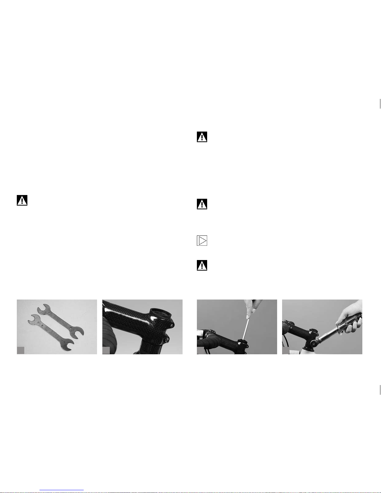
49
b
c
da
8.2 Readjusting a Conventional Headset.
The adjustment tolerance between there being play in the bearings and
them being set too tight is very small. The bearings are susceptible to
damage. If you want to try it nevertheless, you need two large and at
open-end wrenches (a).
Release the threaded top nut and tighten the upper threaded bearing
cap a little clockwise. Retighten the top nut.
A too tight adjustment may damage the headset and impair the
performance of the bicycle.
8.3 Readjusting an Aheadset®.
(*Aheadset® is a registered trade mark for threadless systems of DiaCompe)
The distinct feature of this system is that the stem does not sit within the
fork steerer tube, but rather slips over the fork steerer tube, which in this
case is threadless (b). The stem is thus an important part of the headset
bearing. Its clamping force secures the bearing in the correct running
position. Instead of special tools you need in most cases only one or two
Allen keys as well as a torque wrench to adjust the Aheadset
®
. Release
the clamping bolt(s) located on the side of the stem by one to two complete turns. Using an Allen key, gently tighten the countersunk adjusting
bolt on top a little, e.g. by a quarter turn (c).
Do not overtighten the upper bolt, it only ser ves the purpose of
adjusting the bearing play, not of securing the stem!
Re-align the stem with the frame so that the handlebars are not slanted
when the wheel points straight ahead. Make sure the front wheel is in
line with the top tube and the stem. Tighten the clamping bolts of the
stem (d). Use a torque wrench and never exceed the maximum tighten-
ing torque! You will nd the prescribed values in chapter “Recommended Tightening Torques”, directly on the components and/or in
the manuals of the component manufacturers.
Bear in mind that by overtightening the bolts the stem can
crush the steerer tube.
Check the headset for play as described above. Take care not to overtighten the bearings, as this could easily damage them.
If you do not succeed in adjusting the bearing, this can have
several reasons. If you are in doubt or if you have any questions,
please contact your BMW partner!
Check the secure seat of the stem by taking the front wheel
between your legs and tr ying to turn the handlebars and stem
relative to the wheel. A loose stem can throw you off your
bicycle.
Page 54
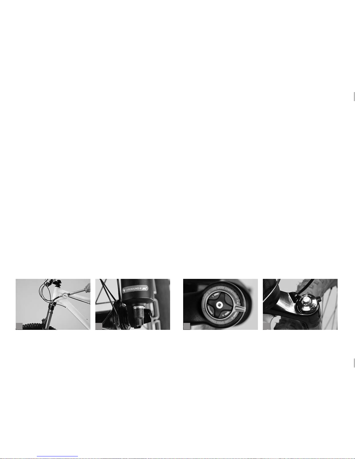
50
b
c
da
9 SUSPENSION.
9.1 Glossary.
Spring rate or hardness:
The force required to compress the spring a given distance.
A higher rate indicates a higher force requirement per unit of length.
With air springs a higher rate means a higher pressure (a).
Initial spring tension:
The initial spring tension of coil springs and elastomers can be set within
a certain range. This makes the suspension respond only when exposed
to a higher load. The spring rate remains, however, unchanged. Heavier
riders cannot compensate a too soft spring rate with a higher initial tension.
Rebound damping:
The damping which controls the rate at which the fork extends after being compressed (b+c).
Compression damping:
The damping which controls the rate at which the fork compresses (c).
Sag:
The distance by which the rear shock or fork compresses (should
compress) when the rider assumes his normal riding position while the
bicycle is stationary.
Lockout (c+d):
Device blocking the fork or the damper from absorbing shocks thus
ensuring a smooth riding on tarred roads without vibrations. A lockout
must not be activated when riding off-road or downhill.
Platform damping:
Increases compression damping and helps eliminate bob. Compared to
the lockout mechanism the suspension is not inactivated entirely.
Page 55
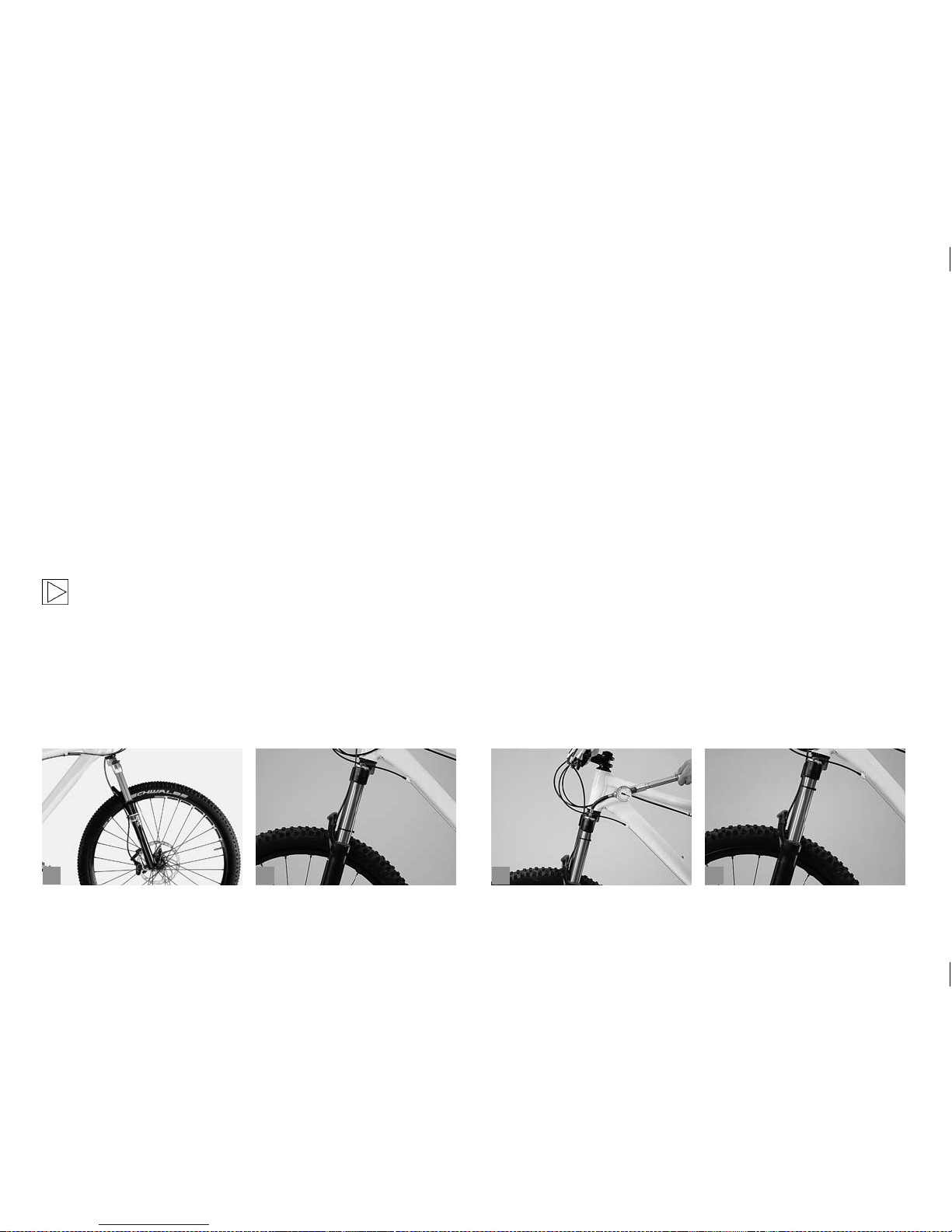
51
b
c
da
9.2 Suspension Forks.
9.2.1 Adjusting the Spring Rate.
Most mountain, cruise and touring bikes are equipped with suspension
forks (a). This feature gives you better control of your bicycle when riding cross-country or on rough road surfaces. It noticeably reduces the
strain on you and your bicycle caused by the mechanical shocks from
the terrain.
Suspension forks differ in their spring elements and in the way the
damping is realised. Suspension is provided by coil springs, special
types of plastic known as elastomers or sealed air compartments or
combinations of these options. The damping is usually done by oil or by
the self-damping properties of the elastomers.
For more information see the suspension glossary heading this
chapter.
In order to work optimally, the fork has to be adjusted to the weight of the
rider and the intended purpose. Be sure to have this adjustment carried
out by a bicycle specialist shop of your trust before delivery. With an air
sprung suspension fork you have to inate it before your rst ride. The
fork adjustment depends on the rider’s weight and the sitting posture.
Please bear in mind that the suspension fork should sag a little under the
rider’s weight. When the front wheel passes through a depression in the
ground, the spring extends and the suspension fork will smooth out the
uneven surface. If the selected air pressure or initial spring tension is too
high, this effect is lost because the wheel will already be fully extended.
This means the loss of an important feature affecting both safety and
comfort.
Cross-country and marathon racers usually run less sag than downhillers or more comfort loving freeriders. For cross-country and marathon
riding the rear shock should yield by about 10-25 % of its total travel, for
enduro and freeriding by about 20-40 %.
Put a cable tie (b) onto the stanchion tube so that you can still slide it
easily along the tube’s exposed section.
To measure the maximum shock travel release all the air pressure from
the suspension fork. Then inate the fork to the recommended air
pressure and measure the distance between the cable tie and the upper
edge of the lower tube.
Page 56
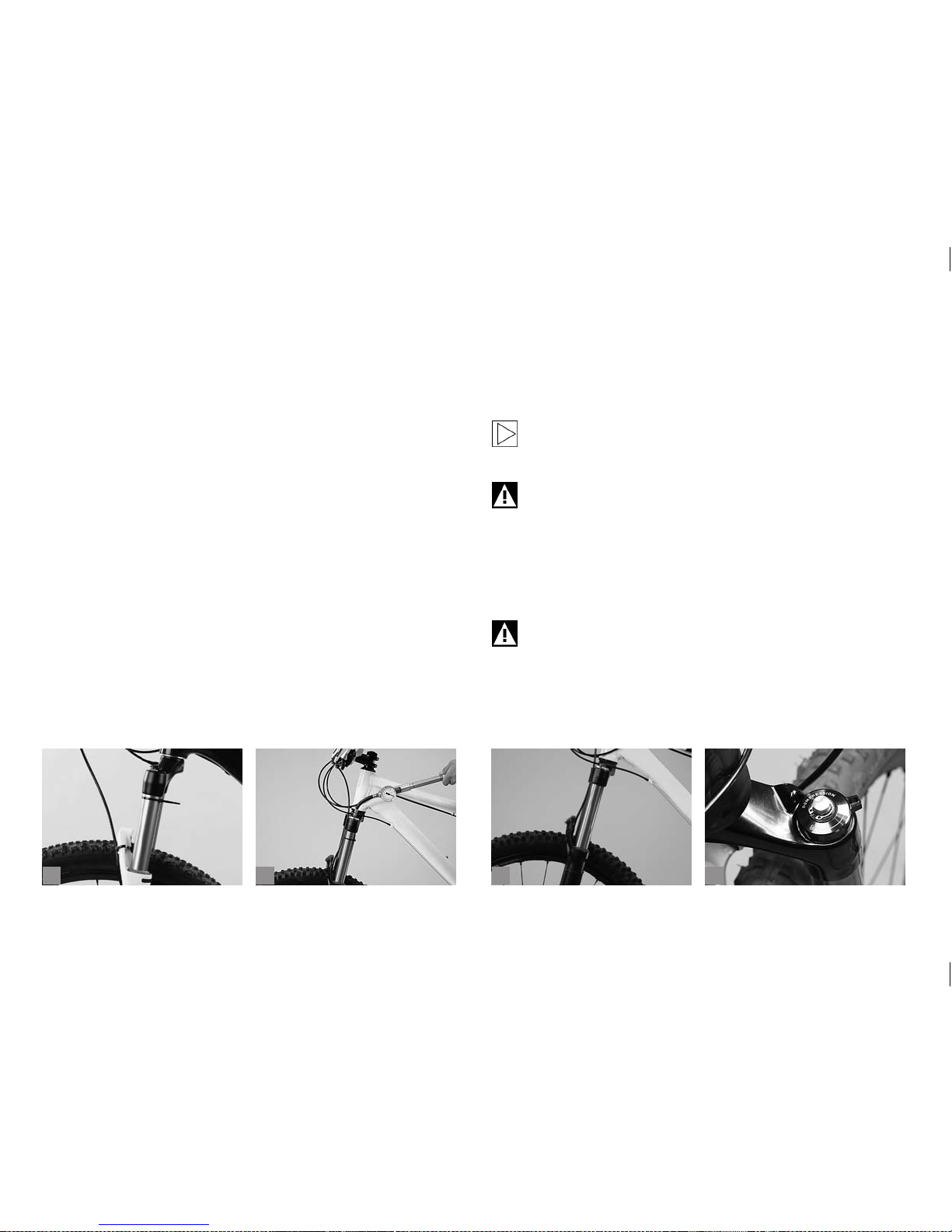
52
b
c
da
The initial tension of most forks with coil springs or elastomer llings can
be altered to a limited degree by adjusting the preload knob located on
the fork crown connecting the stanchion tubes. In the event there is no
adjusting device, the coil spring or elastomer lling need to be replaced.
In the case of oil/air forks, the spring rate is adjusted by the air pressure
in the fork ((c) p. 51). The pressure must be checked at regular inter vals
with a special shock pump which is normally made available by the fork
manufacturer. Please follow the recommendations of the manufacturer.
Ride your bicycle on different kinds of surface and check after wards the
travel of the cable tie ((d) p. 51). The difference is the rear shock’s travel
you have used. If the cable tie has moved a few millimetres only, your
fork is too rm. Reduce the air pressure of air sprung forks or the initial
spring tension of coil springs. If your rear shock is still too rm, have the
springs replaced.
If the cable tie has moved along the entire travel range (a) or if you can
hear the fork hit the end of its travel, the spring is too soft. In this case
the initial spring tension/pressure must be increased (b). If the adjustment range of the coil springs is too small, have the springs replaced at a
bicycle specialist shop of your trust.
Check the pressure of air sprung forks at regular inter vals and follow the
recommendations of the manufacturer. If the available setting options do
not cover your needs, you will need to replace the springs or dampers.
Many manufacturers have tuning and retrotting kits on offer. If you are
in doubt or if you have any questions, please contact a bicycle specialist
shop of your trust! When replacing any parts be sure to only use parts
that bear the appropriate mark and, to be on the safe side, original spare
parts. Your BMW partner will be pleased to order the original spare parts
for you!
Fork manufacturers include instructions with their deliveries.
Read them carefully before changing any settings or doing any
maintenance work on your rear shock.
The suspension fork should be set up and adjusted in such
a way that it does not reach the end of its travel (known as
bottom out). A spring rate which is too soft (or too low an air
pressure) can usually be heard or felt as a “clunk” type noise.
This noise is caused by the sudden complete compression of
the suspension fork as it reaches bottom out. If the suspension
fork frequently reaches bottom out, it will become damaged
over time, and so will the frame.
Suspension forks (c) are designed in a way to absorb shocks.
If the fork is too rigid and jammed, the terrain induced shocks
pass directly into the frame without any damping. The frame is
normally not designed to withstand such undamped stresses.
If your bicycle is equipped with a suspension fork including
lockout (d), you should keep in mind not to activate the lockout
function when riding over rough terrain, but only when riding
over smooth terrain (tarred roads, smooth tracks).
Page 57
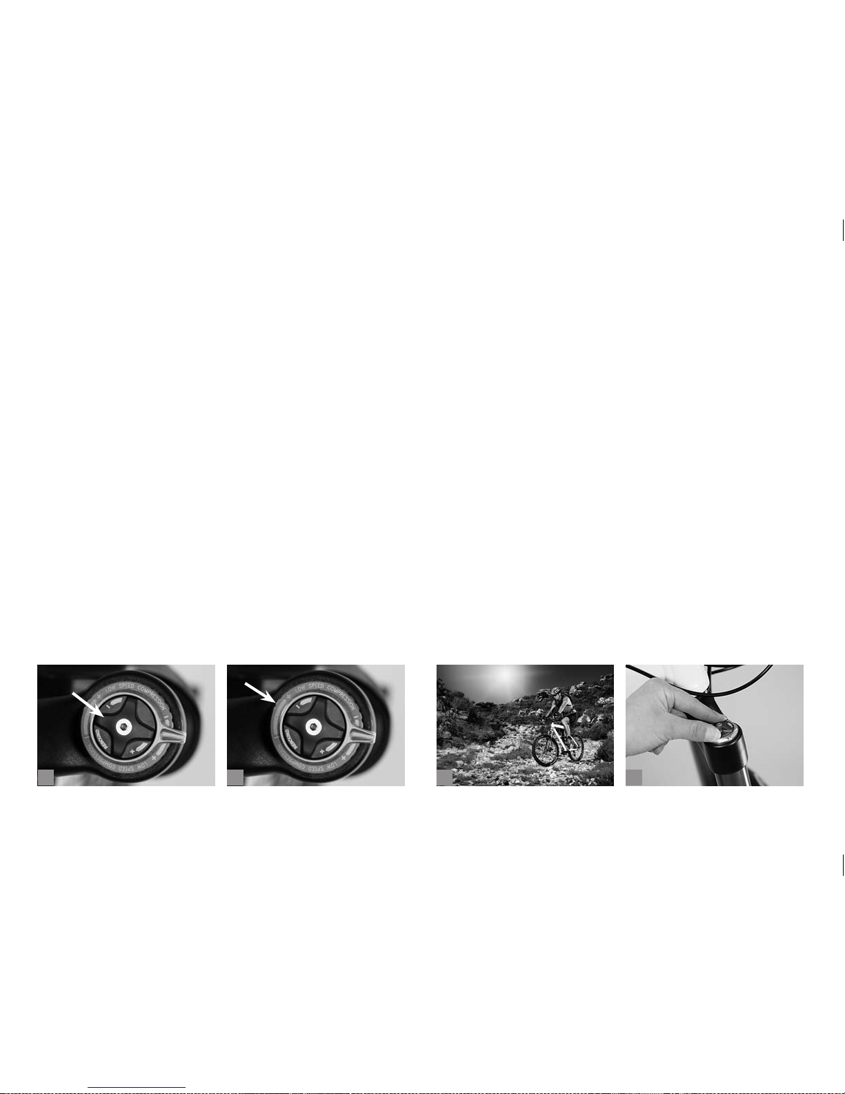
53
b
c
da
9.2.2 Adjusting the Damping Control.
The damping is adjusted by valves inside. These valves are designed to
modify the ow rate of the oil and hence the speed with which the fork
legs move in and out. In this way it is possible to optimise the bicycle’s
reaction to obstacles. Furthermore, any oscillatory movement while
pedalling can be reduced. For long uphill rides involving hard pedalling
out of the saddle it is advisable to activate the lockout mechanism. On
the other hand, for downhill rides on uneven ground it may be better to
open the damping system more or less completely.
Suspension forks with adjustable damping are tted with an adjusting
knob that is (mainly) red to slow down or accelerate the rebound movement (a). The second knob, if available, is to adjust the speed of the
compression movement (b).
The adjusting process changes the ow rate of the oil contained within
the suspension fork as it passes through valves and chambers internally.
Some models provide for separate adjustment of compression and
rebound damping. Experience has shown that it is best to begin with the
compression stage entirely open and to rst adjust the rebound stage.
Adjusting the suspension fork is a delicate job, as even a small change
on the adjuster can have a big effect. Try approaching the exact setting
you need in increments no larger than a quarter turn from the “Open”position.
Rebound is considered satisfactory when the suspension fork cycles
once after descending from a high kerb. If you turn the knob too far, the
oil inside will ow very slowly and the rebound will be at maximum. This
will result in a sluggish rebound movement, and the suspension fork will
not recover when exposed to a quick series of impacts.
Turning the adjusting knob in the other direction reduces rebound,
making the suspension fork rebound faster.
Once this is done, adjust the compression stage. This is to control the
rate at which the rear shock compresses. Adjusting the compression
adjuster towards the closed or maximum position will give you a rmer,
less active ride. Take your bicycle for a test ride on different kinds of
surface (c).
If the suspension fork hits the end of its travel (bottom out) several times,
you will need to change its spring rate (d).
If the damping does not suit your needs, in spite of your adjusting, or if in
the case of coil spring elements you need more than three to four turns
for the initial spring tension, you may need to replace the suspension
elements. The replacement is a job best left to a bicycle specialist shop
of your trust.
Page 58
54
ba
Do not actuate the lockout function (of the suspension fork)
when riding over rough terrain, but only when riding over
smooth terrain (roads, smooth tracks) (a).
Do not turn any screws on your rear shock in the vague hope of
adjusting it somehow. You could release the fastening mechanism, thus causing an accident. All manufacturers normally
mark adjustment devices with a scale or “+” and “-“ signs (b).
Suspension fork manufacturers normally include instructions
with their deliveries. Read them carefully before changing any
settings or doing any maintenance work on your rear shock.
A too strong damping of the fork can result in a sluggish
rebound movement with a suspension fork that will not recover
when exposed to a quick series of impacts. Risk of accident!
Do not ride your bicycle, if the suspension fork bottoms out.
This could damage the suspension fork itself as well as the
frame.
When mounting a new front tyre, make sure there is enough
clearance between tyre and fork crown as the fork compresses
entirely. The front wheel might get jammed. Risk of accident!
9.2.3 Adjusting the Travel.
The travel of some suspension fork models allow travel adjustment.
With some models reducing the travel makes for an easier uphill riding.
A reduced travel may result in a modied spring characteristic of the fork
making the fork either softer or rmer. This can reduce the comfort of
suspension.
With other models, changing the travel does not result in a modied
spring characteristic. The suspension fork provides an identic comfort of
suspension with a however clearly reduced travel.
Do not ride with a reduced travel over rough terrain or downhill!
For more information on adjusting the travel, please read the
enclosed instructions of the suspension fork manufacturer!
Page 59
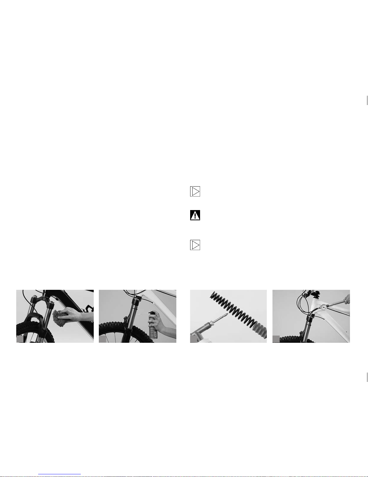
55
b
c
da
9.2.4 Maintenance.
Suspension forks are components of sophisticated design that require
regular maintenance and care. This has led almost all suspension fork
manufacturers to establish service centres where you can have your
fork thoroughly checked and overhauled at regular intervals according to
use, e.g. once a year. Be sure to have all bolted connections checked at
regular intervals by your BMW partner.
The following routines are essential for rear shock maintenance:
Make sure the sliding surfaces of the stanchion tubes are absolutely
clean. Clean the fork with water and a soft sponge after every ride (a).
After washing your bicycle, spray the stanchion tubes of the suspension
fork with a little grease spray (b) or apply a ver y thin lm of hydraulic oil.
Do not use a steam jet or aggressive cleaning agents! Ask your BMW
partner for an appropriate lubricant.
If your fork has an elastomer lling, you should regularly clean (c) and
lubricate the synthetic springs with a non-corrosive resin-free grease.
Some fork manufacturers provide special greases for fork maintenance.
Be sure to follow the recommendations of the manufacturers.
Forks with air springs have to be checked regularly for air pressure, as
the air escapes over time (d).
Suspension forks are components of sophisticated design that require
regular maintenance and care. This has led almost all suspension fork
manufacturers to establish service centres where you can have your
fork thoroughly checked and overhauled at regular intervals according to
use, e.g. once a year. Be sure to have all bolted connections checked at
regular intervals by your BMW partner.
Suspension forks are constantly being sprayed with water and
dirt from the front wheel. Clean them with lots of water after
every ride.
Suspension elements are of sophisticated design. The maintenance routines and above all the disassembly of the suspension elements are jobs best left to a bicycle specialist shop of
your trust.
Be sure to have your suspension fork checked by a service
centre of the fork manufacturer once a year at least.
Page 60
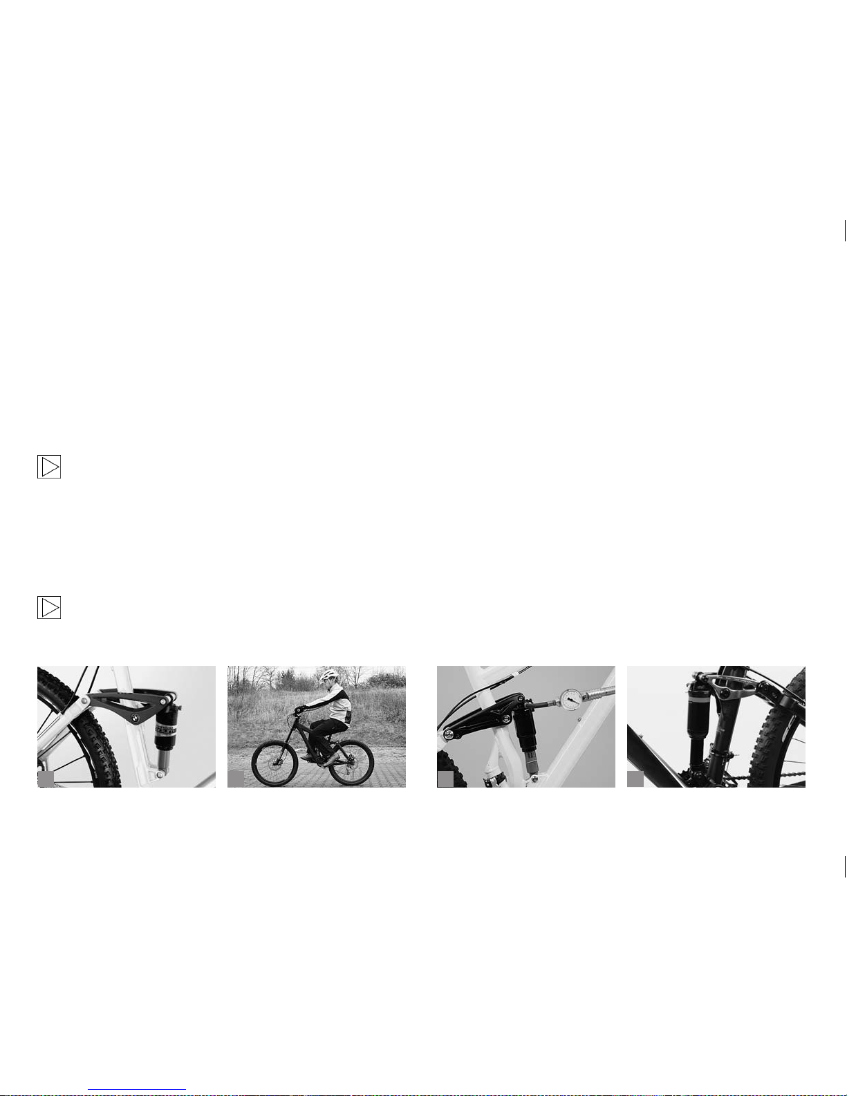
56
b
c
da
9.3 Rear Shock.
Full suspension bicycles are equipped not only with a suspension fork
but also with movable rear stays which are sprung and damped by a
shock absorber (a). This feature gives you better control of your bicycle
when riding cross-country or on rough road surfaces. It noticeably
reduces the strain on you and your bicycle caused by the mechanical
shocks from the terrain. With rear shocks this normally works with an air
spring element or, less frequently, with coil springs. Damping is usually
controlled by the use of oil. Depending on the system the rear shock has
one or more bearing axles with at least two bearings each.
For more information see the suspension glossary heading this
chapter.
9.3.1 Adjusting the Seating Position.
Full suspension bicycles sag a little when you sit on the saddle. This
causes the saddle to tilt a little backwards, an ef fect which can be
compensated by adjusting the position of the saddle. If you have trouble
sitting, try lowering the nose of the saddle a little compared to your usual
position.
Full suspension bicycles have a greater ground clearance than
bicycles without rear suspension. With a properly adjusted
saddle height you will not be able to reach the oor with your
feet. Set the saddle a little lower to begin with (b) and practise
getting on and off the saddle.
9.3.2 Adjusting the Spring Rate.
In order to work optimally, the rear shock has to be adjusted to the
weight of the rider and the intended purpose. Be sure to have this
adjustment carried out by a BMW partner or a bicycle specialist shop of
your trust before deliver y.
With an air spring element you have to inate the rear shock before your
rst ride (c). The rear shock adjustment depends on the rider’s weight
and the sitting posture.
Please bear in mind that the rear swing arm of the rear shock should sag
a little under the rider’s weight. When the rear wheel passes through a
depression in the ground the spring can then extend and the suspension
mechanism will smooth out the uneven surface. If the selected air pressure is too high, this effect is lost because the wheel will already be fully
extended. This means the loss of an important feature affecting both
safety and comfort.
To aid measurement you can use the rubber o-ring often available on the
shock’s shaft (d), which slides further down the shaft as the rider gets
on the bicycle or slip a cable tie onto the thinner tube of the rear shock
so that it can still shift easily along the tube.
Page 61
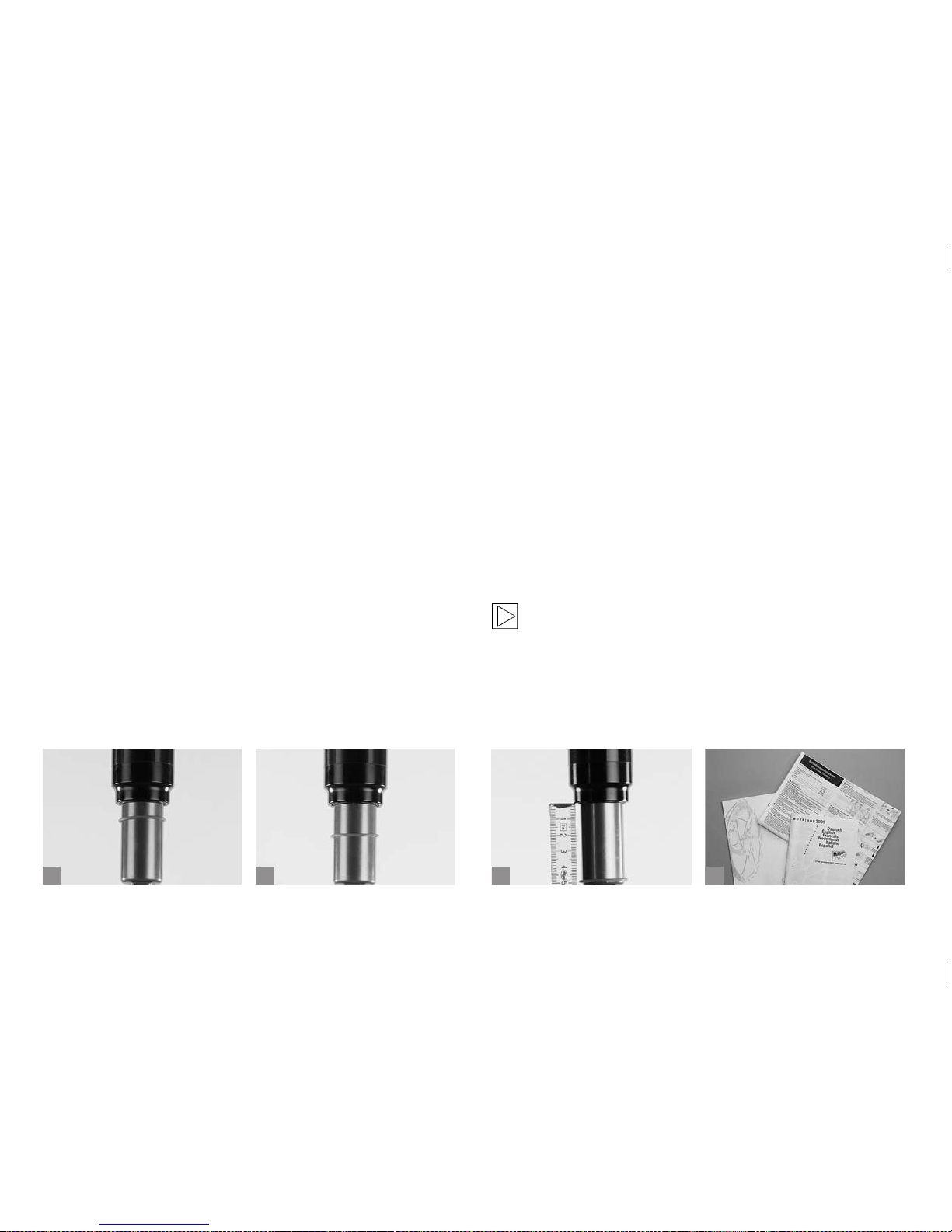
57
b
c
da
Cross-country and marathon racers usually run less sag than downhillers or more comfort loving freeriders. For cross-country and marathon
riding the rear shock should yield by about 10-25 % of its total travel (a),
for enduro and freeriding by about 20-40 % (b).
To measure the maximum shock travel release all the air pressure from
the rear shock. Compress the rear shock completely. Then inate the
shock absorber to the recommended air pressure and measure the
distance between the rubber o-ring/cable tie and the upper edge of the
shock body (c).
In the case of oil/air sprung rear shocks, the spring rate is adjusted by
the air pressure in the damper. The pressure must be checked at regular
intervals with a special shock pump that is normally included in the delivery of the rear shock manufacturer or available in a specialist cycle shop.
Please follow the recommendations of the manufacturer.
Ride your bicycle on different kinds of surface and check after wards the
travel of the rubber o-ring/cable tie. The difference is the rear shock’s
travel you have used. If the rubber o-ring/cable tie has moved a few mil-
limetres only, your rear shock is too rm. Reduce the air pressure of air
sprung rear shocks or the initial spring tension of coil springs. If your rear
shock is still too rm, have the springs replaced.
If the rubber o-ring/cable tie has moved along the entire travel range or
if you can hear the rear shock hit the end of its travel, the spring is too
soft. In this case the initial spring tension/pressure must be increased. If
the adjustment range is too small, have the springs replaced at a bicycle
specialist shop of your trust. The rear shock should not reach the end of
its travel (bottom out), which can usully be heard clearly. If the rear shock
frequently reaches bottom out, it will become damaged over time.
Check the pressure at regular intervals and follow the recommendations
of the manufacturer. If the available setting options do not cover your
needs, you will need to replace the springs or dampers. Many manu-
facturers have tuning and retrotting kits on offer. If you are in doubt
or if you have any questions, please contact your BMW partner or a
bicycle specialist shop of your trust! When replacing any parts be sure
to only use parts that bear the appropriate mark and, to be on the safe
side, original spare parts. Your BMW partner will be pleased to order the
respective original spare parts for you!
Almost all manufacturers deliver their dampers/rear shocks
with instructions (d). Read them carefully before changing any
settings or doing any maintenance work on your rear shock.
Page 62

58
b
c
da
The rear shock should be set up and adjusted in such a way
that it does not reach the end of its travel (known as bottom
out). A spring rate which is too soft (or too low an air pressure)
can usually be heard or felt as a “clunk” type noise. This noise
is caused by the sudden complete compression of the rear
shock as it reaches bottom out. If the rear shock frequently
reaches bottom out, it will become damaged over time, and so
will the frame.
Rear shocks are mounted on full-suspension frames (a) in a
way that they absorb shocks from the terrain. If the damper is
too rigid and jammed, the terrain induced shocks pass directly
into the frame without any damping. The frame is normally
not designed to withstand such undamped stresses. If your
bicycle is equipped with a rear shock including lockout (b), you
must therefore keep in mind not to activate the lockout function when riding over rough terrain, but only when riding over
smooth terrain (tarred roads, smooth tracks).
9.3.3 Adjusting the Damping Control.
The damping is adjusted by valves inside. These valves are designed to
modify the ow rate of the oil and hence the speed with which the rear
swing arm moves in and out. In this way it is possible to optimise the
bicycle’s reaction to obstacles. Furthermore, any oscillatory movement
of the rear frame while pedalling can be reduced. For long uphill rides
involving hard pedalling in sitting it is advisable to eliminate the damp-
ing. For this purpose some rear shock models are tted with a lockout
device. For downhill rides on uneven ground the lockout mechanism
must not be activated.
Rear shocks with adjustable damping are tted with an adjusting knob
that is (mainly) red to slow down or accelerate the rebound movement
(c+d). The second knob, if available, is to adjust the speed of the com-
pression movement.
The adjusting process changes the ow rate of the oil contained within
the suspension fork as it passes through valves and chambers internally.
Some models provide for separate adjustment of compression and
rebound damping. Experience has shown that it is best to begin with the
compression stage entirely open and to rst adjust the rebound stage.
Adjusting the suspension fork is a delicate job, as even a small change
on the adjuster can have a big effect. Try approaching the exact setting
you need in increments no larger than a quarter turn from the “Open”position.
Rebound is considered satisfactory when the rear frame cycles once
after descending from a high kerb. If you turn the knob too far, the oil
inside will ow very slowly and the rebound will be at maximum. This
will result in a sluggish rebound movement, and the rear shock will not
recover when exposed to a quick series of impacts.
Page 63
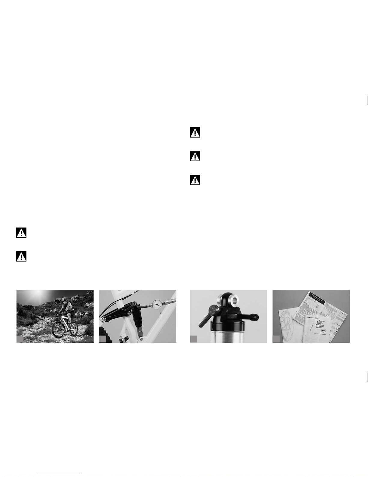
59
b
c
da
Turning the adjusting knob in the other direction reduces rebound,
making the rear shock rebound faster. Once this is done, adjust the
compression stage. This is to control the rate at which the rear shock
compresses. Adjusting the compression adjuster towards the closed
or maximum position will give you a rmer, less active ride. Take your
mountain bike for a test ride on different kinds of surface (a).
If the rear shock hits the end of its travel (bottom out) several times, you
will need to change its spring rate, i.e. to increase the pressure (b). Make
sure not to exceed the maximum pressure indicated on the rear shock.
If the damping does not suit your needs, in spite of your adjusting, or if in
the case of coil spring elements you need more than three to four turns
for the initial spring tension, you may need to replace the suspension
elements. The replacement is a job best left to a bicycle specialist shop
of your trust.
Do not actuate the lockout function (c) (of the rear shock) when
riding over rough terrain, but only when riding over smooth terrain (roads, smooth tracks).
Do not turn any screws on your rear shock in the vague hope of
adjusting it somehow. You could release the fastening mechanism, thus causing an accident. All manufacturers normally
mark adjustment devices with a scale or “+” and “-“ signs.
Rear shock manufacturers normally include instructions with
their deliveries (d). Read them carefully before changing any
settings or doing any maintenance work on your rear shock.
A too strong damping can result in a sluggish rebound move-
ment with a rear shock that will not recover when exposed to a
quick series of impacts. Risk of accident!
Do not ride your bicycle, if the rear shock reaches bottom out.
This could damage the rear shock itself as well as the frame.
9.3.4 Maintenance.
Rear shocks and rear frames are components of sophisticated design
that require regular maintenance and care. This has led almost all rear
shock manufacturers to establish service centres where you can have
your rear shock thoroughly checked and overhauled at regular intervals
according to use, e.g. once a year. Be sure to have all bolted connections
checked at regular intervals by your BMW partner.
Page 64
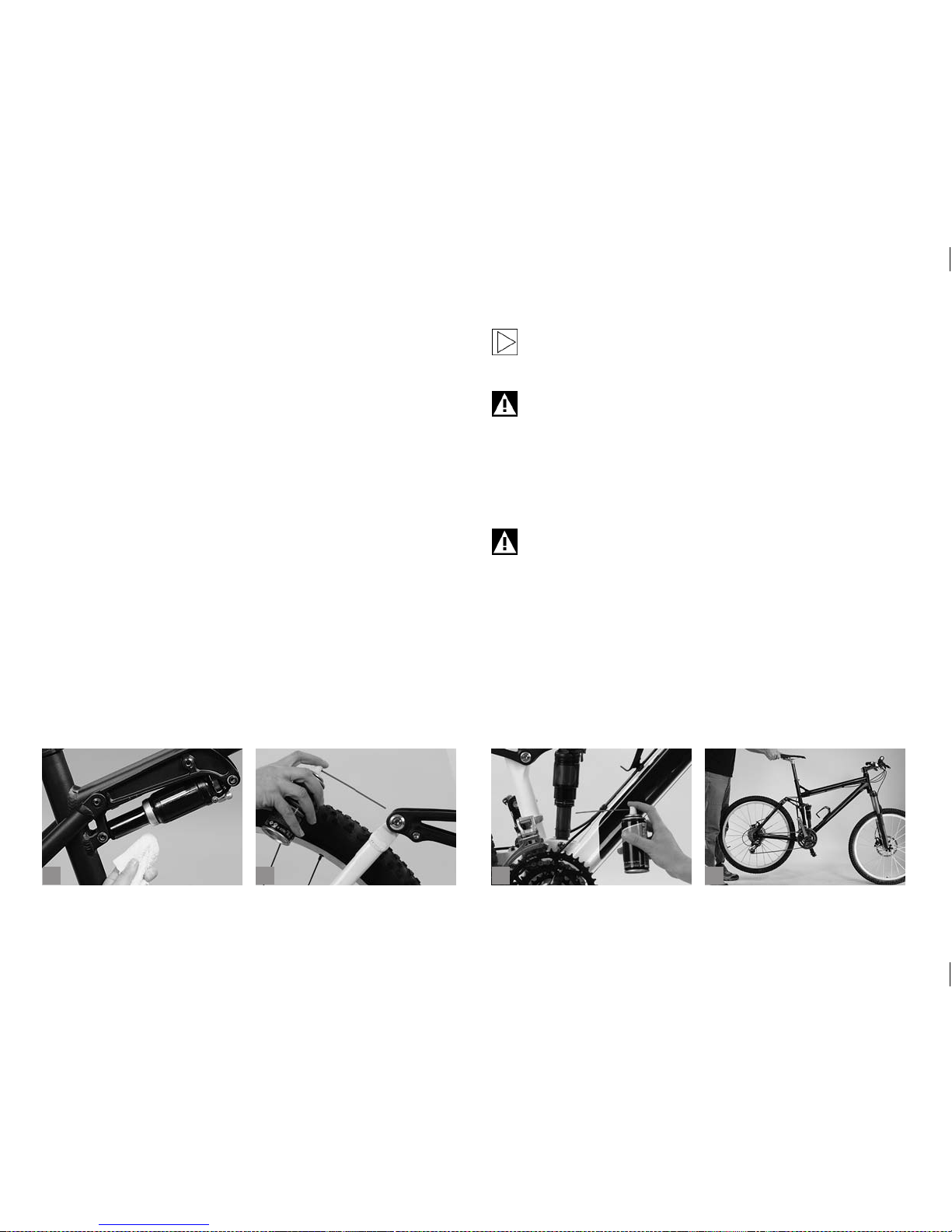
60
b
c
da
The following routines are essential for rear shock maintenance:
Rear shocks with air springs have to be checked regularly for air pressure, as the air escapes over time. Make sure the sliding surface of the
piston rod is absolutely clean. Clean the rear shock and rear frame, in
particular the bearings, with water and a soft sponge after every ride (a).
After washing your bicycle, spray the piston rod of the rear shock and the
bearing areas with a little grease spray (b+c) or apply a very thin lm of
hydraulic oil.
Do not use a steam jet or aggressive cleaning agents! Ask your BMW
partner for an appropriate lubricant.
Regularly check the rear swing arm for side-to-side play and the bearing
of the rear shock for vertical play. To check the rear swing arm for play,
lift the mountain bike by the saddle and try to move the rear wheel from
side to side. If necessar y, ask a helper to keep the front part of the frame
still while you do this.
To check the rear shock for play place the rear wheel gently on the
ground and lift it again a little (d). Check for any rattling. If you nd any
play, ask your BMW partner or a bicycle specialist shop of your trust to
eliminate it without delay.
Rear shocks are constantly being sprayed with water and dirt
from the rear wheel. Clean them with lots of water after ever y
ride.
Suspension rear frames and rear shocks are components of sophisticated design that require regular maintenance and care.
This has led almost all rear shock manufacturers to establish
service centres where you can have your rear shock thoroughly checked and overhauled at regular intervals according
to use, e.g. once a year. Be sure to have all bolted connections
checked at regular intervals by your BMW partner or a bicycle
specialist shop of your trust.
Suspension elements are of sophisticated design. The maintenance routines and above all the disassembly of the suspension elements are jobs best left to a bicycle specialist shop of
your trust. Be sure to have your rear shock checked by a service centre of the rear shock manufacturer once a year at least.
Page 65
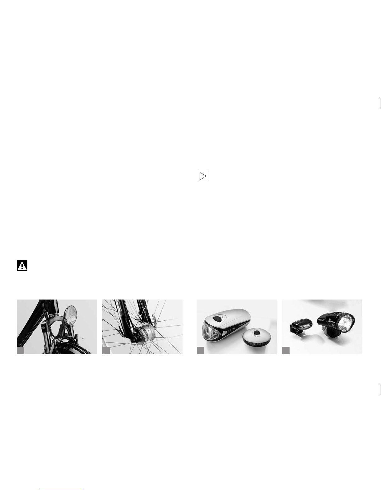
61
b
c
da
10 LIGHTING.
Anyone cycling on public roads is required by law to have a properly
working set of lights (a) (see chapter “Legal Requirements for Rid-
ing on Public Roads”). It is important to be familiar with the design of
the lighting set so that you can repair it yourself in the event of a failure.
The dynamo (generator) produces the current required for operating the
light bulbs and back. It has two cables attached to it, one running to the
front light and the other to the rear light and back.
10.1 Hub Dynamo.
Hub dynamos (b) are built into the hub of the front wheel. They are virtually non-wearing and extremely effective. Some models are switched
on electronically, some others mechanically. Hub dynamos are either
engaged by a lever at the handlebars or directly at the front lamp. Other
models offer the comfort of being switched on and off automatically by
means of a sensor.
In case you need more information on your lighting, contact
your BMW partner.
10.2 Troubleshooting.
After punctures the second most common malfunction is lighting failure.
First inspect the front and rear light bulbs. Check whether the laments
are intact. Bulbs with a black tint are a sure indication of a defect.
On bicycles with a batter y-powered lighting (c+d) a failure is
usually due to at batteries. Therefore, check the charge state
of the batteries at regular intervals or take replacements with
you.
Check the contacts and the sockets in the lamp housings of the front
and rear lights ((a+b) p. 62). White or greenish stains are a sign of corrosion. Remove the corrosion layer with a screwdriver, emery cloth or the
like until the contact surfaces are shiny again.
If your bicycle is tted with a dynamo lighting, inspect the cables along
their entire length and check them for defects. Check all contact points.
Pin and socket connectors tend to corrode if exposed to salt and rain.
Take the connectors apart and stick them together again.
Page 66
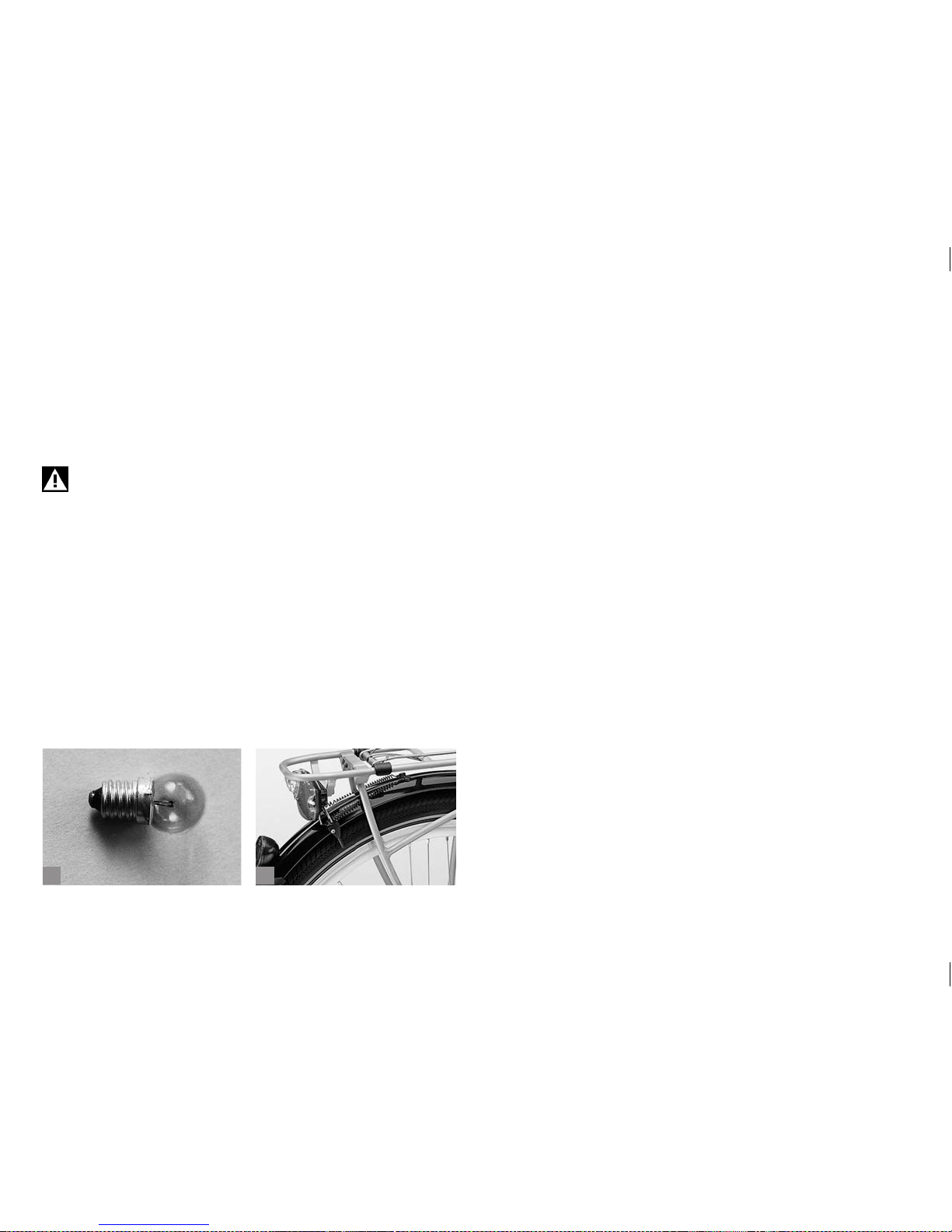
62
ba
If you still cannot nd the cause of the trouble, try supplying the current
using a battery (4.5 volt battery). If the lamps light up, the dynamo itself
might be the cause of the trouble.
If the lamps do not light up, move the batter y closer to the lamps step by
step looking out for the moment when a current starts to ow. If that still
does not help, contact your BMW partner or a bicycle specialist shop of
your trust.
An incomplete or inoperative set of lights is not only against
the law, it is also a hazard to your life. Cyclists riding in the dark
without a light are liable to be overlooked and at risk of getting
involved in serious accidents!
Page 67
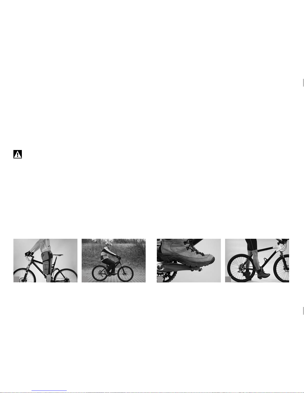
63
b
c
da
11 ADJUSTING THE BICYCLE TO
THE RIDER.
Your body measurements are decisive for the frame size of your bicycle.
Make particularly sure there is enough space between your crotch and
the top tube so that you do not hurt yourself, if you have to get off your
bicycle quickly (a).
If you have a very small frame, there may be a danger of your
foot colliding with the front wheel. Therefore, make sure your
cleats are properly adjusted.
By choosing a specic type of bicycle you roughly determine the posture
you will be riding in (b). However, some components are designed in a
way that you can adjust them to your proportions to a certain degree,
such as seat post, stem and brake levers. Contact your BMW partner.
He will see to your wishes the next time you leave your bicycle at the
workshop, e.g. for the rst inspection.
After any adjustment/assembly work, be sure to make a short functional
check as described in chapter “Before Every Ride” and do a test ride
in an area away from trafc. This will allow you to safely check whether
everything is in good order.
All tasks described in the following require the know-how of a mechanic
and appropriate tools. Increase the tightening torque bit by bit, checking
the t of the component in between. Use a torque wrench and never exceed the maximum tightening torque! You will nd the prescribed values
in chapter “Recommended Tightening Torques”, directly on the
components and/or in the manuals of the component manufacturers.
11.1 Adjusting the Saddle to the Correct
Height.
The correct saddle height for almost all bicycle types is the height which
gives maximum pedalling comfort and efciency. When pedalling, the
ball of your foot should be positioned above the centre of the pedal
spindles (c). With your feet in this position you should not be able to
stretch your legs completely straight at the lowest point, otherwise your
pedalling will become awkward.
Check the height of your saddle with at-soled shoes. This is best done
with suitable cycling shoes.
Sit on the saddle and put your heel on the pedal at its lowest point (d).
Your leg should be fully stretched and your hips should remain horizontal.
To adjust the saddle height loosen the quick-release lever (see chapter
“How to Use Quick-Releases and Thru Axles“) or the binder bolt
of the seat post clamp at the top of the seat tube. The latter requires
appropriate tools, e.g. an Allen key, with which you turn the bolt two to
three turns anticlockwise. Now you can adjust the seat post.
Page 68
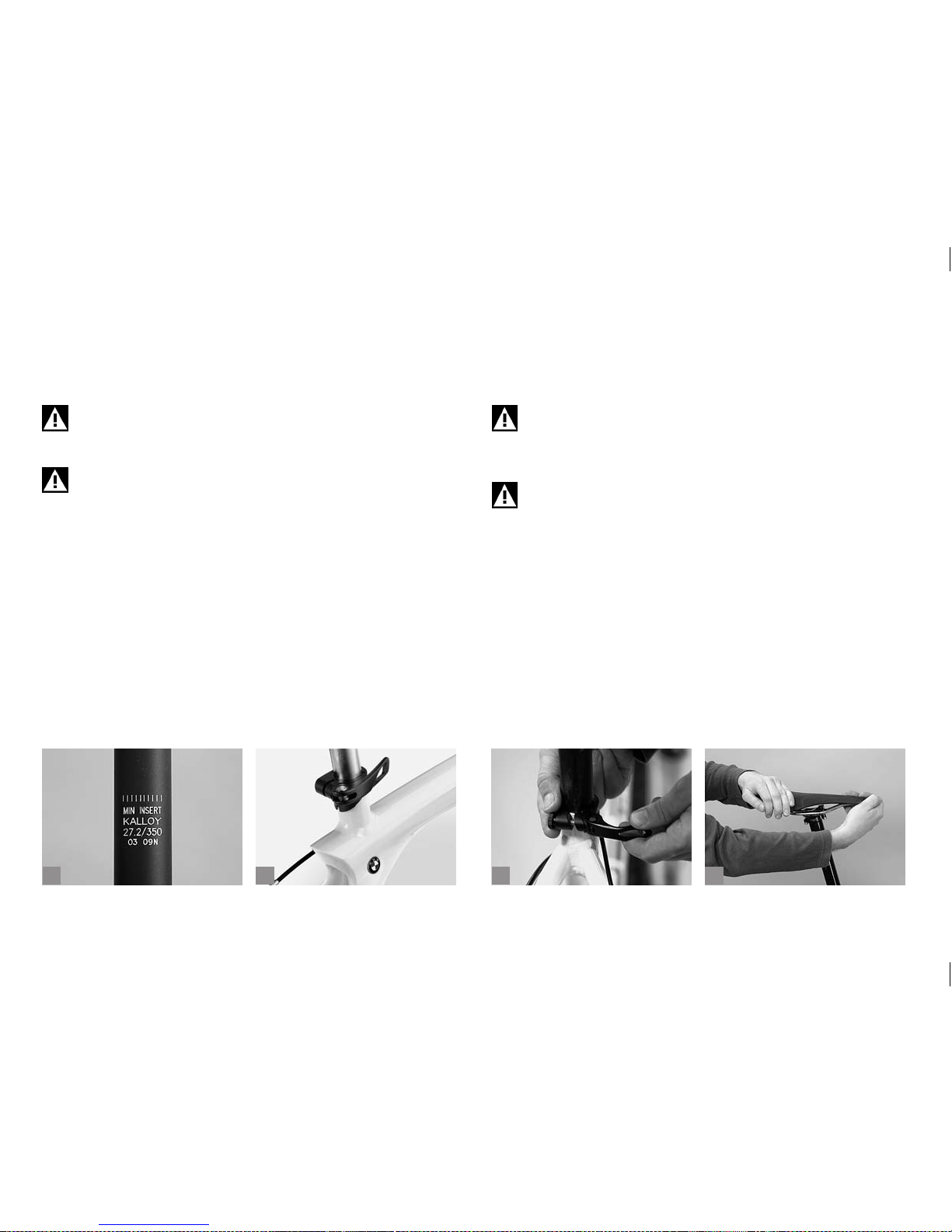
64
b
c
da
Be sure not to pull out the seat post too far - the mark on the seat post
(max., min., stop or the like) should always remain within the seat tube (a)
– and to grease the sur face of an aluminium or titanium seat post that is
inserted into a seat tube made of aluminium, titanium or steel.
Do not use brute force, if the seat post does not move easily
inside the seat tube or if it cannot be tightened sufciently, ask
your BMW partner for advice!
The minimum insertion depths marked on seat post and frame
may differ. Be sure to insert the seat post to the deepest insertion depth!
Align the saddle with the frame by using the saddle nose and the bottom
bracket or top tube as a reference point.
Clamp the seat post tight again by closing the quick-release (b+c), as
described in chapter “How to Use Quick Releases and Thru Axles”
or by turning the seat post binder bolts clockwise in half turns. You
should not need much strength in your hands to clamp the seat post
sufciently tight. Otherwise the seat post does not match the frame.
Verify in between that the seat clamp is suf ciently tight by taking hold
of the saddle at both ends and then trying to rotate the seat post inside
the seat tube (d). If it does rotate, gently retighten the clamping bolt by
half a turn and do the check again.
Tighten carefully by approaching the prescribed maximum
torque in small steps (0.5 Nm increments) whilst constantly
checking the proper t of the component. Never exceed the
maximum tightening torque indicated by the manufacturer!
Do not overtighten the binder bolt of the seat post clamp.
Otherwise the seat post or the frame can be damaged. Risk of
accident!
Does the leg stretch test now produce the right result? Check by moving
your foot and pedal to the lowest point. When the ball of your foot is
exactly above the pedal centre in the ideal pedalling position, your knee
should be slightly bent. If it is, you have adjusted the saddle height correctly. Check whether you can touch the ground safely while sitting on
the saddle by stretching your feet to the oor. If you cannot, you should
lower the saddle a little, at least to begin with.
Page 69
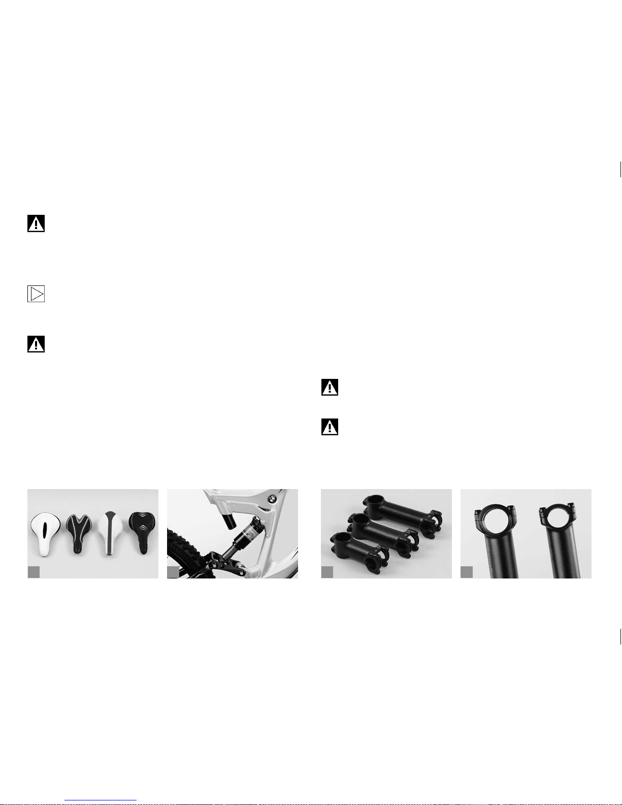
65
b
c
da
Never ride your bicycle with the seat post drawn out beyond
the limit, maximum, or stop mark! The seat post might break or
cause severe damage to the frame. If your bicycle has a long
seat tube continuing beyond the top tube, the seat post should
at least reach below the level of the top tube and the tip of the
rear stays!
If sitting on the saddle causes you trouble, e.g. because it
numbs your crotch, this may be due to the saddle. A bicycle
specialist shop of your trust has a very wide range of saddles
available and can offer advice on position (a).
With full-suspension mountain bikes the seat post should not
project from the seat tube at lowest saddle height, as otherwise the rear shock arm may collide with the seat post during
compression (b).
11.2 Adjusting the Height of the
Handlebars.
The height of the handlebars determines how much your upper body will
be inclined forward. Lowering the handlebars gives you a streamlined
position and brings more weight to bear on the front wheel. However, it
also entails an extremely forward leaning posture which is tiring and less
comfortable, because it increases the strain on your wrists, arms, back,
upper body and neck.
There are three different systems that allow vertical adjustment of the
handlebars, i.e. conventional, adjustable and Aheadset
®
-stem. These
systems require special knowledge. In this regard, the descriptions
hereafter may be incomplete. If you have the slightest doubt, ask your
BMW partner for help.
The stem (c) is one of the load bearing parts of your bicycle.
Changes to it can impair your safety. If you are in doubt or if you
have any questions, please contact your BMW partner!
Stems come in varying lengths as well as shaft and binder
tube diameters (d). If you opt for a stem of inappropriate sizing, handlebars and stem may break and result in an accident.
When replacing any parts be sure to only use parts that bear
the appropriate mark and, to be on the safe side, original spare
parts. Your BMW partner will be pleased to order the respective
original spare parts for you!
Page 70
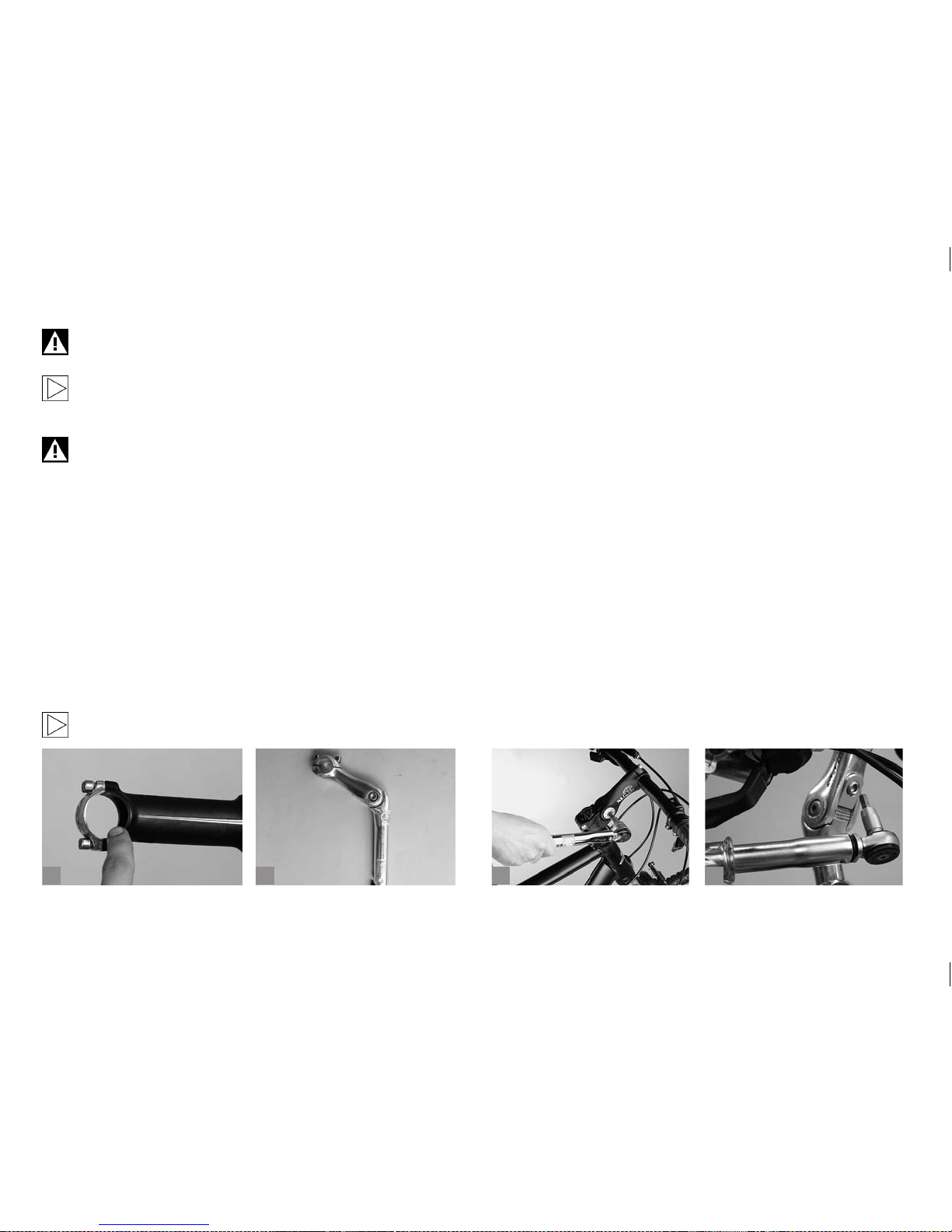
66
Make sure the handlebar-stem-combination is approved by the
handlebar and/or stem manufacturer.
Check whether the handlebar clamping surface of the stem is
free of sharp edges (a). Ask your BMW partner for professional
advice.
The bolted connections of stem and handlebars have to be
tightened to the prescribed tightening torques. If you disregard
the prescribed values, handlebars or stem may come loose or
break. Use a torque wrench and never exceed the maximum
tightening torque! You will nd the prescribed values in chapter
“Recommended Tightening Torques”, directly on the components and/or in the manuals of the component manufacturers.
11.2.1 Adjustable Stems.
There are various solutions for adjusting the tilt of the front part of
adjustable stems (b):
Some designs use bolts on the sides of the joint, others have bolts coming from above or below, and some versions are equipped with additional
locking mechanisms or adjusting bolts.
Ask your BMW partner to explain you both function and adjustment of your stem or let him do that work.
Release the side clamping bolt at the joint (c) by two to three turns at the
most, i.e. without unscrewing it all the way. If you still cannot move the
stem, it is being held in place by a ratchet or integrated locking mecha-
nism. If the stem is tted with a locking mechanism, release the holding
bolt located on the top or bottom side (d) of the stem a little. In the case
of a ratchet mechanism you will nd the bolt on the side.
Adjust the stem according to your needs.
Gently retighten the bolt of the locking mechanism, until it engages.
Bolts located on the side only have to be tightened gently. If there are
no side bolts, you have to tighten the bolt of the locking mechanism. If
the stem of your bike has a ratchet mechanism, make sure its surfaces
engage snugly as you tighten the side bolt. Retighten the bolt on the
side of the joint, if necessary.
Any bolts located on the top or bottom side of the stem have to be
released as far as necessar y to disengage the ratchet mechanism and to
move the front part. It is usually not necessary to remove the bolts completely. Retighten the bolts after setting the stem to the desired height.
b
c
da
Page 71
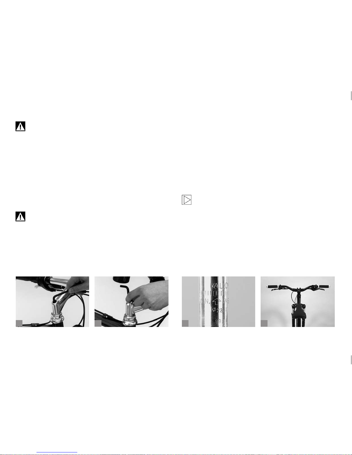
67
Changing the position of the stem alters the position of handlebars, brake and shift levers. Readjust them as described in
chapter “Adjusting the Tilt of Handlebars, Bar Ends and
Brake Levers….“.
To adjust the stem angle release the angle locking bolt rst. Press the
bolt to the left until the toothed washer becomes visible and the stem
angle allows adjustment.
Adjust the stem angle according to your needs.
Press the toothed washer back to the right until it engages with the
ratchet mechanism of the stem.
Tighten the angle locking bolt of the stem clamping evenly.
Never use brute force when adjusting the stem. The application
of force might damage the ratchet mechanism. This would no
longer allow a reliable, tight clamping of the stem in its adjusted
position. Risk of accident!
11.2.2 Conventional Stems.
Handlebars with conventional stems allow limited vertical adjustment.
This is done by moving the stem up or down inside the fork steerer tube.
Release the expander bolt by two to three complete turns (a). The stem
should now turn freely inside the fork. If it does not, release the bolt by
tapping it gently with a rubber hammer.
With Allen bolts, you need to stick the Allen key into its head rst, as it is
normally countersunk and therefore impossible to be hit directly. Then
gently tap the key with the rubber hammer (b).
Never tr y to unscrew the top race when you only want to adjust
the stem, as you will otherwise alter the bearing play.
Now you can move the handlebar/stem unit up and down as a whole. Be
sure not to pull out the stem too far. The mark on the stem (max., min.,
max., stop, limit or the like) should always remain within the tube (c). Setting the stem to a lower position can only add to your safety!
Straighten the handlebars so that they are symmetrical with respect to
the front wheel (d).
b
c
da
Page 72
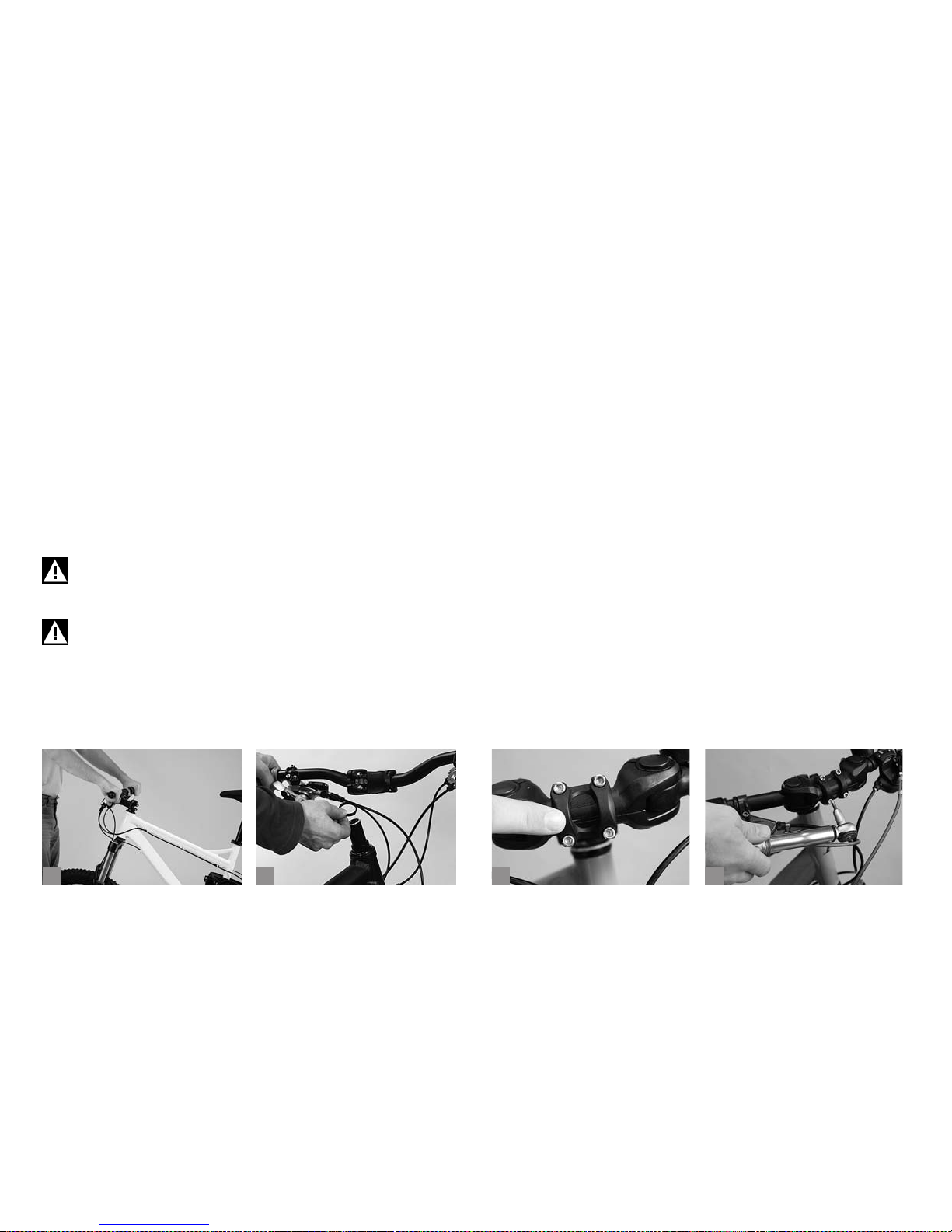
68
Retighten the expander bolt with a torque wrench. Tighten carefully by
approaching the prescribed maximum torque in small steps (0.5 Nm
increments) whilst constantly checking the proper t of the component.
Never exceed the maximum tightening torque indicated by the manufacturer!
Make sure the stem is rmly xed by taking the front wheel between
your legs and trying to turn the handlebars and stem relative to the
wheel (a). If there is movement, please increase the tightening torque.
If the handlebars are still too high or too low, you can replace the stem.
This can be quite a big job, as it may mean taking off and remounting all
the ttings on the handlebars. Inform yourself at a bicycle specialist shop
of your trust about the various stem types available.
Never ride a bicycle with a stem drawn out beyond the mark for
the maximum permissible height! Check all bolted connections
and do a brake test before you set off!
Stems come in most different lengths and shaft and binder
tube diameters. If you opt for a stem of inappropriate sizing,
handlebars and stem may break and result in an accident.
11.2.3 Stems for Threadless Systems,
the Aheadset
®
-System.
(*Aheadset® is a registered trade mark of Dia-Compe)
On bicycles with Aheadset® the stem also serves to adjust the initial
headset bearing pressure. If you change the position of the stem you
have to readjust the bearings (see chapter “Headset”). The vertical
setting range is determined by the intermediate rings, also referred to
as spacers (b). In the case of ip-op stem models the stem can be
mounted the other way round to achieve a different handlebar height.
This adjustment is a job best left to a bicycle specialist shop of your
trust!
11.2.4 Adjusting Adjustable Handlebar Systems (A.H.S.).
Check whether the clamping area (c) of the A.H.S. is accurately centred
in the handlebar clamp of the stem.
Adjust the A.H.S. tilt to your personal needs.
Tighten the handlebar clamping bolt(s) at the stem to the tightening
torques prescribed by the stem manufacturer (d).
b
c
da
Page 73
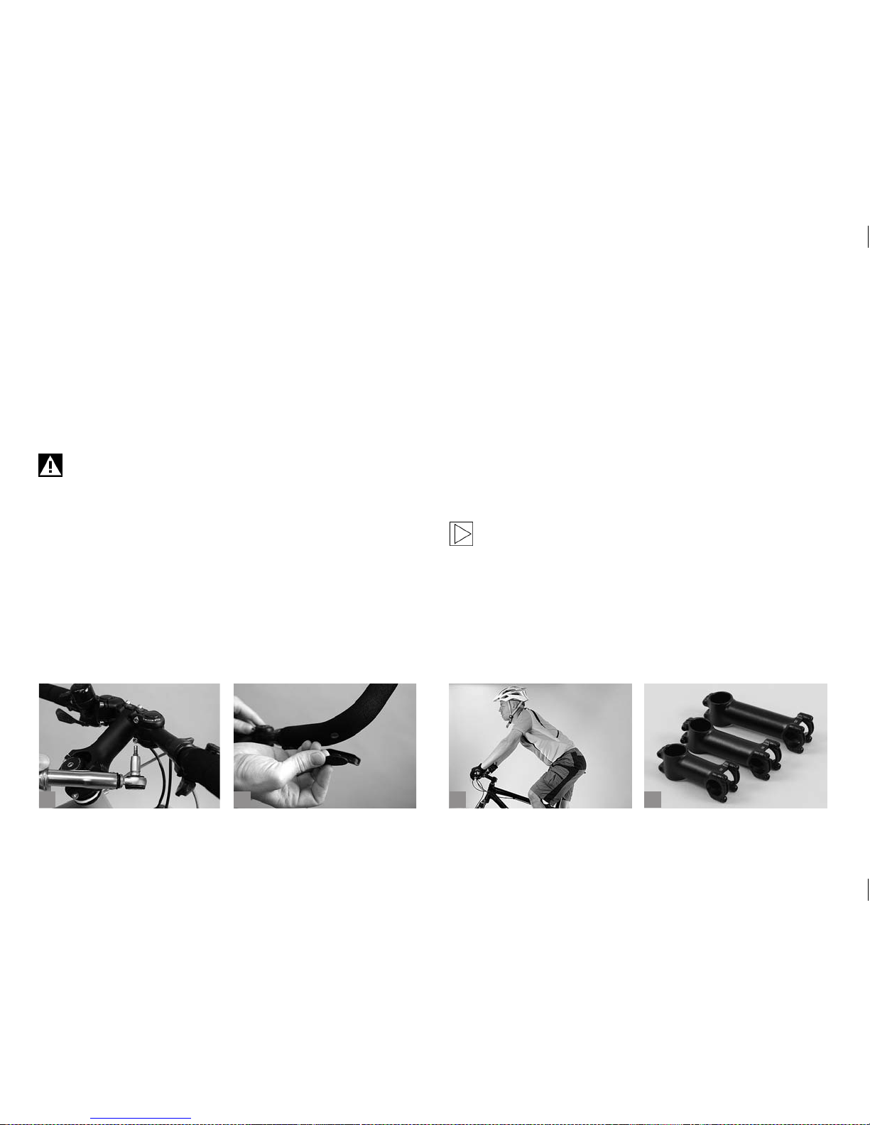
69
Bring the A.H.S. grips into a position that matches your personal needs.
To do so release the clamping bolts at the joint.
After you have found the ideal position for you, retighten the clamping
bolts (a) to a tightening torque of 5.5 Nm.
Adjust the shift/brake levers and grips on the handlebars to your wishes.
Slide the expander cones of the bar ends onto the outer ends of the
A.H.S.
Make sure the clamping surfaces are always clean and free of
grease!
Position the bar ends to your personal needs.
Tighten the clamping bolts of the bar ends to a tightening torque of 23
Nm.
Do not forget to insert the according plugs into the ends of the A.H.S.
(b).
11.3 Correcting the Fore-to-Aft Position
and Tilt of the Saddle.
The inclination of your upper body, and hence your riding comfort and
pedalling power, are also inuenced by the distance between the grips
of the handlebars and the saddle (c). This distance can be altered
slightly by changing the position of the saddle rails in the seat post
clamp. However, this also inuences your pedalling. Whether the saddle
is positioned more to the front or to the back of the bicycle will alter how
rearward the pedalling position of your legs is.
You need to have the saddle horizontal in order to pedal in a relaxed
manner. If it is tilted, you will constantly have to lean against the handlebars to prevent yourself from slipping off the saddle.
The setting range of the saddle is very small. Replacing the
stem allows you to make far bigger adjustments to the rider’s
fore-to-aft position, as stems come in different lengths (d). In
doing so you may achieve differences of more than ten centimetres. In this case you usually would have to adjust the length
of the cables – a job best left to the mechanic of a bicycle
specialist shop of your trust!
b
c
da
Page 74
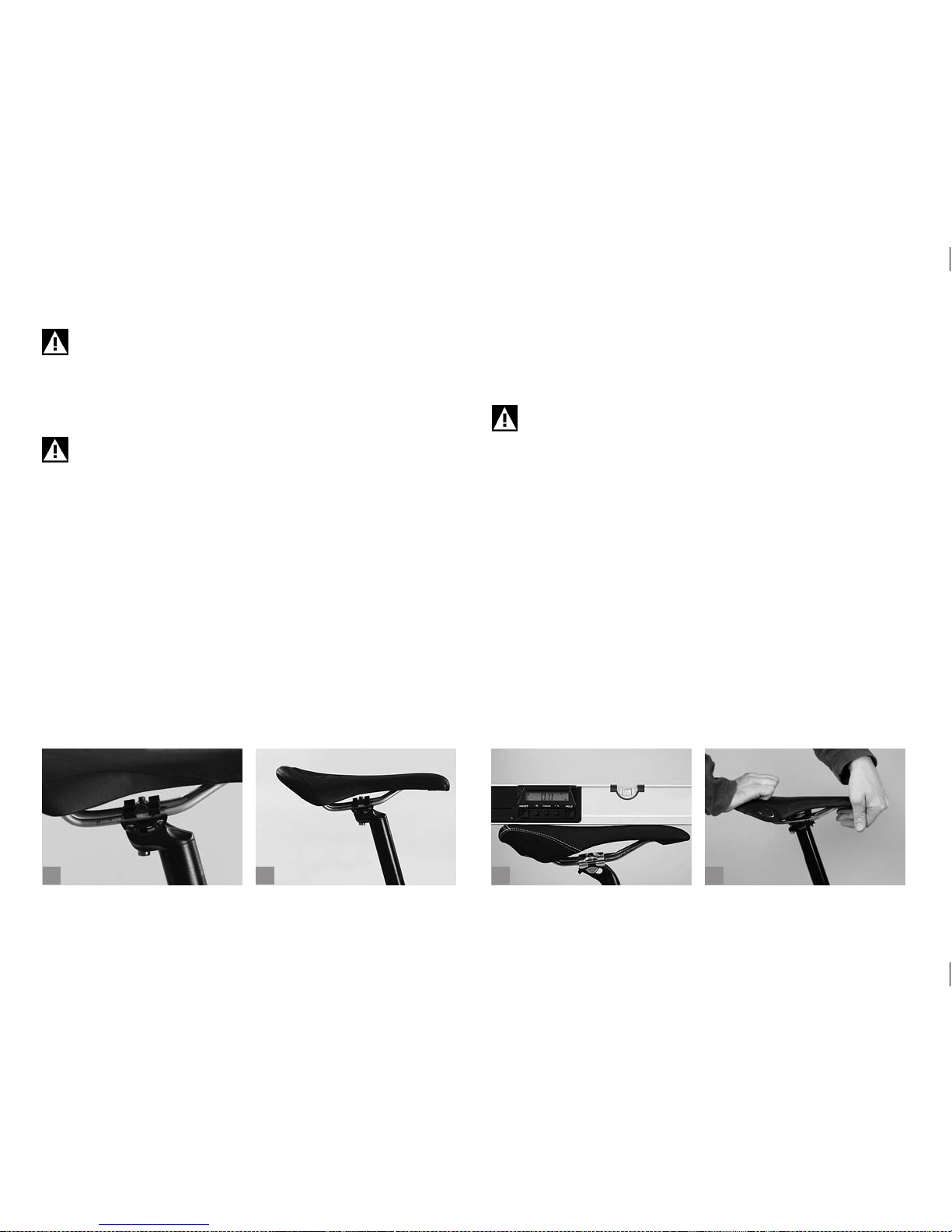
70
b
c
da
Note that the bolted connections of the seat post have to be
tightened to the prescribed tightening torques. Use a torque
wrench and never exceed the maximum tightening torque! You
will nd the prescribed values in chapter “Recommended
Tightening Torques”, directly on the components and/or in
the manuals of the component manufacturers.
Make sure the saddle is not clamped in the curved sections of
the saddle rails (a).
11.3.1 Adjusting Saddle Position and Tilt.
With patent seat posts (b) a single bolt xes the clamping mechanism,
which controls both the tilt and the horizontal position of the saddle.
Some seat posts have two bolts for a ner adjustment of the tilt.
Release one or both bolts at the top of the seat post. Turn the bolt(s) two
to three turns anticlockwise at the most, otherwise the whole assembly
can come apart.
Move the saddle forward or backward by sliding its rails in the loosened
seat post clamp. You may have to give the saddle a light tap to move it.
Please observe the markings on the saddle rail.
Make sure the seat of the saddle remains horizontal (c) as you retighten
the bolt(s). The bicycle should stand on level ground while you adjust the
saddle.
Retighten the bolt(s) with a torque wrench according to the instructions
of the manufacturer. After fastening the saddle, check whether it resists
tilting by bringing your weight to bear on it once with your hands at either
end of the saddle (d).
Check the bolts by using a torque wrench once a month according to the values indicated in the enclosed manuals or directly
on the components.
Page 75
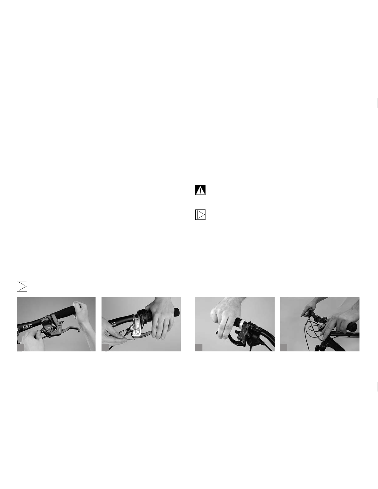
71
b
c
da
11.4 Adjusting the Brake Levers and the
Handlebars.
11.4.1 Adjusting the Brake Lever Reach of Mountain,
Cruise and Touring Bikes.
With most brake systems the distance between the brake levers and
the handlebar grips is adjustable. This gives riders with small hands the
convenience of bringing the brake levers closer to the handlebars. The
length of the rider’s ngers also determines how the lever position for
rst brake contact should be set.
Determine the point, front and rear, at which the brake pads touch the
rims or, with disc brakes, makes contact with the rotor. If this point is
reached after the lever has only travelled a short distance, you will have
to readjust the brakes when altering the reach distance (see chapter
“Brake System“ and the operating instructions of the brake manufacturer). Otherwise the brake pads might drag on the rims.
On most bicycles there is a small headless screw near the point where
the brake cable of a cable brake enters the brake lever mount or at the
lever itself. Turn the screw clockwise and watch how the lever adjusts as
you do so (a).
If you have disc brakes, follow the instructions of the brake
manufacturer.
Hydraulic brakes are also tted with adjusting devices at the brake lever
(b). There are different systems. For more information ask your BMW
partner or a bicycle specialist shop of your trust.
When you have set the levers to the desired reach distance be sure to
check whether there is still enough slack for the brake levers to move a
little before the brake pads hit the rims or make contact with the rotors
(see chapter “Brake System“).
Make sure you cannot pull the brake levers all the way to the
handlebars. Your maximum brake force should be reached
short of this point (c)!
Read the additional instructions of the brake manufacturer.
11.4.2 Adjusting the Tilt of Handlebars, Bar Ends and
Brake Levers of Mountain, Cruise and Touring Bikes.
Handlebar ends are usually slightly bent. Set the handlebars to a position
in which your wrists are relaxed and not turned too much outwards (d).
To adjust the angle of the handlebars, release the Allen bolt(s) on the
underside or front side of the stem. Turn the handlebars to the desired
position. Make sure the handlebars are accurately centred in the stem.
Page 76
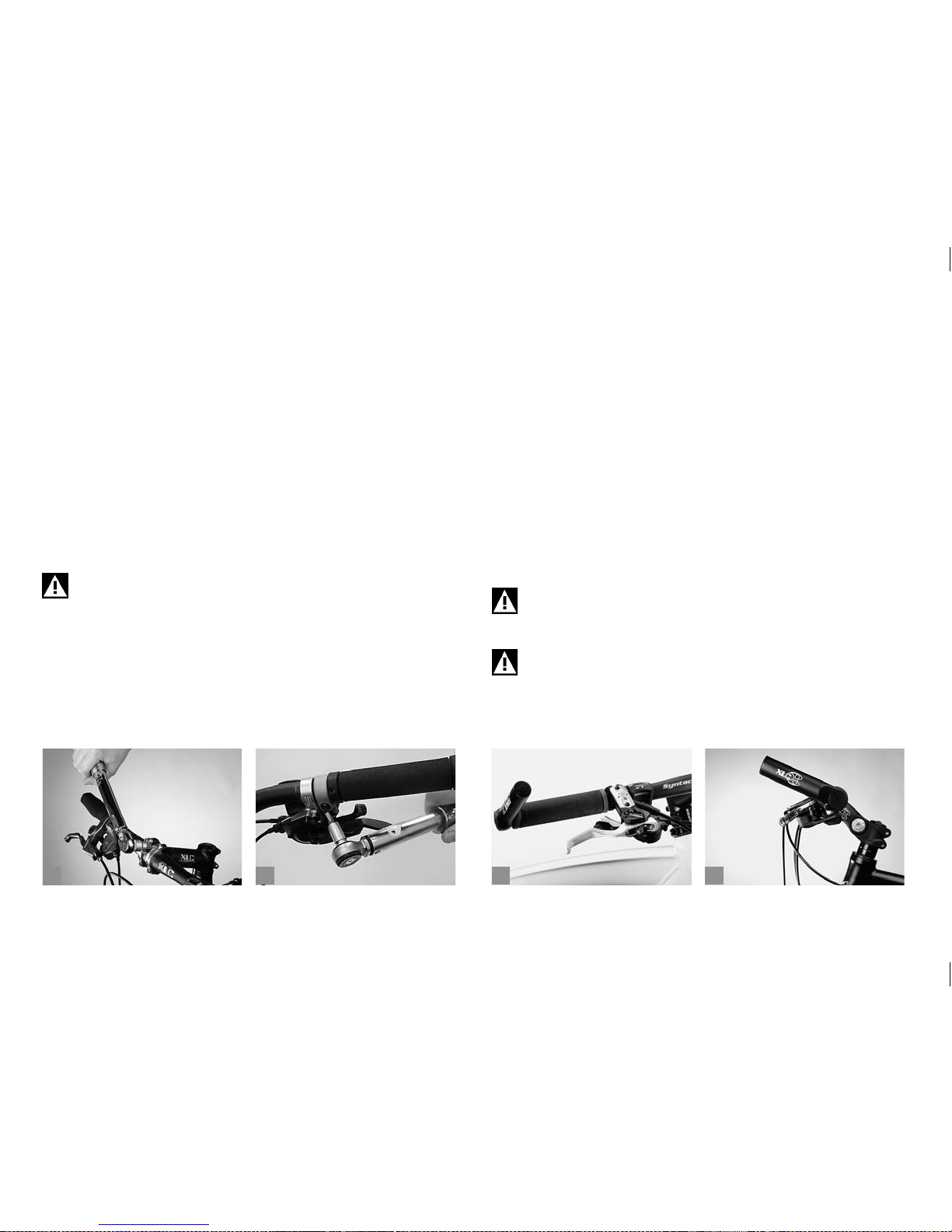
72
b
c
da
Carefully retighten the bolt(s) with a torque wrench (a). Try rotating the
handlebars once clamped in the stem and tighten the bolt a little more, if
necessary. Use a torque wrench and never exceed the maximum tight-
ening torque! You will nd the prescribed values in chapter “Recommended Tightening Torques”, directly on the components and/or in
the manuals of the component manufacturers.
After adjusting the handlebar you need to adjust the brake and shift
levers.
Release the Allen bolt at either grip binder. Turn the levers relative to the
handlebars. Sit in the saddle and place your ngers on the brake levers.
Check whether the back of your hand forms a straight line with the line
of your forearm. Retighten the grips with a torque wrench (b) and do a
twist test!
Note that the bolted connections of the stem, handlebars,
bar ends, and brakes have to be tightened to their specied
torques. Use a torque wrench and never exceed the maximum
tightening torque! You will nd the prescribed values in chapter
“Recommended Tightening Torques”, directly on the components and/or in the manuals of the component manufacturers.
Bar ends (c) give you additional ways of gripping.
They are usually xed in a position that gives the rider a comfortable grip
when pedalling out of the saddle, i.e. almost parallel to the ground or
tilted slightly upwards (by about 25°) (d).
Release the bolts, which are usually located on the bottom side of the
bar ends, by one to two complete turns.
Turn the bar ends to the desired position making sure the angle is the
same on both sides.
Retighten the bolts to the required torque.
Check whether the bar ends are rmly xed by trying to twist them out
of position.
Note that the distance you need to stop your bicycle increases,
while riding with your hands on bar ends. The brake levers are
not always within easy reach.
Never x bar ends in a vertical position or with their ends pointing towards the rear as this would increase the risk of injury in
the event of an accident.
Page 77
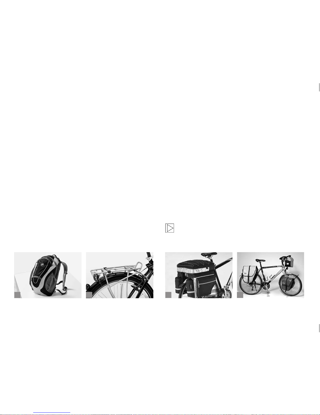
73
b
c
da
12 ALL ABOUT BICYCLES.
12.1 Transporting Baggage.
There are various ways of carrying baggage on a bicycle. Your choice
will primarily depend on the weight and volume of the baggage and on
the bicycle you want to use. Using a bicycle rucksack (a) is a convenient
way of transporting bagage on a bicycle. You can also use pannier racks
or handlebar bags, but some bicycle models do not allow the mounting
of these accessories. If you are in doubt or if you have any questions,
please contact your BMW partner or a bicycle specialist shop of your
trust!
There are, however, many ways of fastening baggage directly to a
bicycle:
The load capacity of pannier racks is classied according to DIN in three
weight levels: 10, 18 and 25 kg. The pannier rack of the BMW touring bike (b) is designed for a load capacity of 25 kg. Please mind the
bicycle’s overall maximum load when transporting baggage. If you t
your bicycle with a pannier rack, make sure it complies with the DIN EN
14872 standard.
It is advisable to carr y baggage in stable pannier bags (c) with a very low
centre of gravity (d).
When buying pannier bags, make sure they are watertight so that your
belongings are protected.
Some cross and mountain bikes without a rear shock can be tted with
a pannier rack. Ask your BMW partner for the xing points and suitable
pannier racks.
Another possibility of transporting baggage are handlebar bags. They
often have quick release fasteners for quick mounting and removal. Handlebar bags are particularly suitable for valuables and photo equipment.
Lowrider bags tted at the front of the bicycle are mounted to the fork by
means of special holders. They are a useful add-on for long tours. They
are well suited for heavy items, as they hardly affect the rider’s control of
the bicycle. Today, there are lowrider bags on the market that are even
suitable for being mounted to suspension forks. If you are in doubt or if
you have any questions, please contact a bicycle specialist shop of your
trust!
We do, however, advise against fastening any baggage to suspension
forks.
Make sure the weight of your baggage is favourably distributed
when loading your bicycle. Heavy items should be carried as
close to the ground as possible. Handlebar bags and bags
mounted to the top of the pannier rack are only suited for light
objects.
Page 78
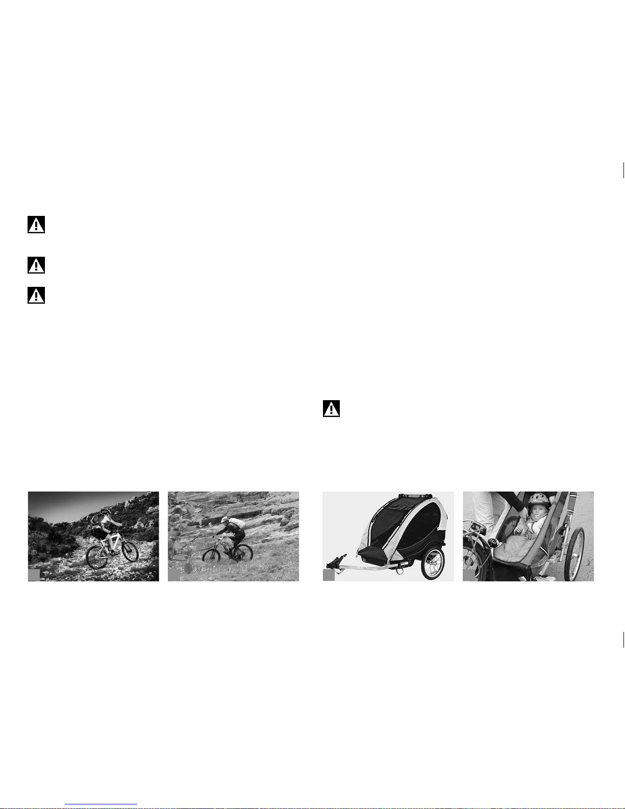
74
b
c
da
Do not overload your bicycle (see chapter “Intended Use”)
and observe the maximum load capacity marked on or impressed in your pannier rack.
Adjust the suspension fork and the tyre pressure to the additional load.
Baggage generally changes the riding characteristics of your
bicycle and increases your stopping distance! Therefore, practise riding a loaded bicycle in a place clear of trafc (a+b).
12.1.1 Transporting Baggage with Full-Suspension Frames.
Seat post supported pannier racks must not be loaded with heavy loads.
Keep in mind that when riding over a bumpy, uneven road the weight
substantially increases (sprung mass). This has a signicant inuence on
the suspension performance. Furthermore, overloading bears the risk of
frame breakage! Therefore, do not load your bicycle with more than 8 kg!
With rear frame supported pannier racks the unsprung mass load
increases and the response of the suspension system becomes more
sluggish.
For this reason we strongly advise against mounting pannier racks to
full-suspension frames.
12.2 Taking Children with You.
The only possible and legal way of transporting children by bicycle is
in special child carriers or trailers (c+d). For more information in this
regard, see chapter “Intended Use”.
12.2.1 Child Carriers.
The child carrier ((a) p.75) is fastened to the frame of the bicycle. The
fastenings are usually designed for intermittent use. The child carrier
can thus be fastened to any bicycle that is equipped with the necessary
ttings.
Only use pannier racks for mounting child carriers that have suitable x-
ing points. Do not overload your pannier rack and be sure to obser ve the
permissible maximum load capacity marked on the rack. Never exceed
the indicated permissible overall load of the bicycle.
Do not mount a child carrier directly to the handlebars! Seat
post supported pannier racks are not approved for child carrier
mounting. Risk of breakage! Full-suspension bicycles do not
allow child carrier mounting.
Page 79
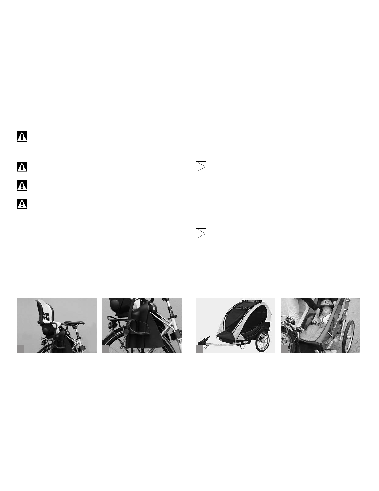
75
b
c
da
Fitness and mountain bikes are not suitable for mounting a
child carrier with special ttings. For more information on other
bicycle types, see chapter “Intended Use”. Consult a bicycle
specialist shop of your trust.
Make it a rule to take your child out of the carrier when parking
the bicycle. Risk of toppling over!
Cover the springs of your saddle so that the child cannot get his
or her ngers pinched between them.
Make sure the child you are taking with you wears a helmet!
It is recommendable to only buy a DIN or GS tested child carrier. Be sure
to fasten the child’s seat belt before you set of f and make sure the feet
are properly seated in the shields (b).
Child carriers have a strong inuence on the bicycle’s riding characteristics. The weight of both carrier and child will make the bicycle somewhat
top-heavy and tend to give you a wobbly ride. Practise getting on and
riding your bicycle with a child on it!
A critical moment is when you have just placed the child in the carrier
because this is when the danger of the bicycle toppling over is greatest.
A good way to obviate this danger is to use a twin leg kickstand to keep
the bicycle stable in standing.
Children must be transported in special child carriers only that
provide sufcient protection for their feet. Please inform yourself about the situation in your country!
12.2.2 Child Trailers.
With special child trailers (c+d) that are towed behind a bicycle you can
transport one or two children. Children can play in the trailer without the
danger of toys falling out. Some models provide the option of mounting a
sunshade or rain shield.
Before hitching a trailer to your bicycle have a look at chapter
“Intended Use” or contact a bicycle specialist shop of your
trust. Note down the trailer type you opt for so that they can
provide you with the information you need.
Page 80
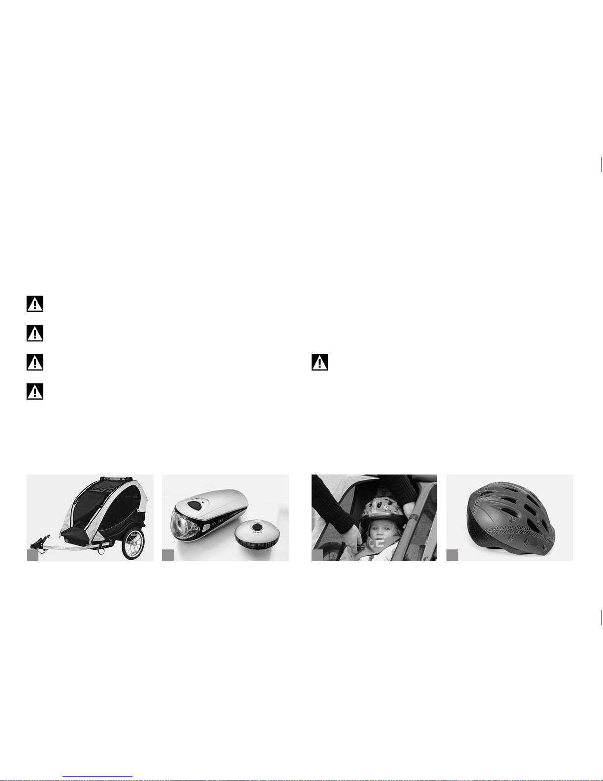
76
b
c
da
Trailers affect the braking behaviour of your bicycle and occupy far more
width than the bicycle would alone. First, practise drawing the trailer
without passengers (a). Mount a long pole with coloured pennant to
your bicycle to increase visibility. It should be tted with all the reectors
that are prescribed for riding on public roads, just like your bicycle. If you
use it in the dark, illuminate the rear end of the trailer with a battery/accumulator-operated lamp (b). Please inform yourself about the regulations
concerning lighting in the country where you are using the trailer.
Always secure the little passenger(s) (c) with the seat belt, as
erratic movements inside the trailer can make it topple over.
Make sure the child you are taking with you wears a helmet (d).
A trailer is an insufcient protection in the event of an accident!
Please note that your stopping distance increases due to the
additional load of the child.
Make sure your bicycle is approved for trailer towing before
mounting one. Trailer towing requires hydraulic brakes! (See
chapter “Intended Use“).
12.2.3 Kids’ Tandem Bicycles / Trailer Systems.
There are different systems on the market that allow a kid’s bicycle to be
attached to an adult bicycle to cycle together with your child on public
roads.
Inform yourself at a bicycle specialist shop of your trust about the various
types of kids’ tandem bicycles.
Some of them are attached to the seat tube of the towing bicycle. This
single point attachment may be a little unstable.
Systems attaching the complete kid’s bicycle to the adult bicycle provide
more stability.
Trailer systems have a strong inuence on the bicycle’s riding
characteristics. The weight of both the attached bicycle and
the child will make the bicycle somewhat top-heavy. It may
tend to wobble. Practise getting on and off your bicycle as well
as cycling. Keep in mind, in particular when turning, that your
bicycle including trailer system is much longer.
Page 81
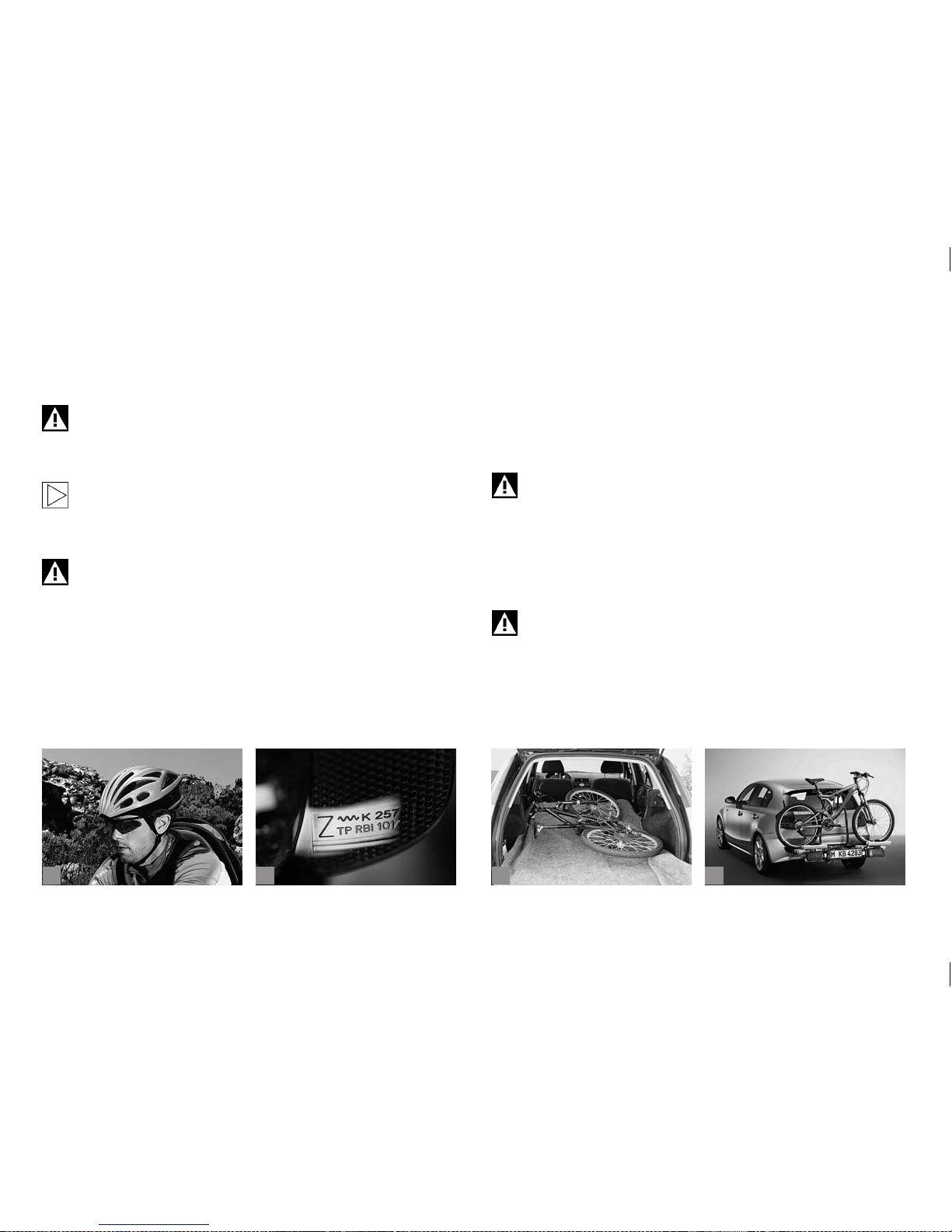
77
b
c
da
These trailer systems also affect the braking behaviour of your bicycle.
Therefore, before riding with a kids’ bicycle tandem on public roads,
practise riding and brake behaviour without passengers in an area free
of trafc.
It is also important for you to practise with your child how to
behave on an attached bicycle during the cycle. Make sure your
child wears a helmet even when riding on a tandem bicycle! Set
a good example by wearing a helmet, as well (a).
Only buy tested trailer systems (e.g. DIN/GS tested systems)
and have them properly mounted. The manuals of the manufacturers that you have obtained together with the trailer
system provide detailed information in this regard.
When riding in the dark the kid’s bicycle attached should be tted with the prescribed lighting, i.e. the latter should be marked
with a wav y line and the letter “K” (b). For more information see
chapter “Legal Requirements for Riding on Public Roads“.
12.3 Taking the Bicycle by Car.
The most convenient way to safely transport your bicycle is to put it into
the boot of your car (c). There the bike is protected from dirt and any
dynamic inuences during the transport. Take care to protect the boot of
the car. If necessary, line the boot before stowing the bike. Interior xing
systems intended to secure the bicycle in the boot can be particularly
helpful.
Always secure the bicycle or bicycle components when putting
it/them into the interior of your car. Parts shifting around can
impair your safety.
If transporting the bicycle inside the boot is impossible, your BMW
partner offers carrier systems (d) which allow bicycle transport without
disassembly. The usual design involves rails xed to the roof of the car
onto which the bicycles are xed with clamps gripping the down tubes.
Make sure to remove all parts of your bicycle (tools, pannier
bags, child carriers etc.) which might come loose during transport and cause an accident!
Page 82
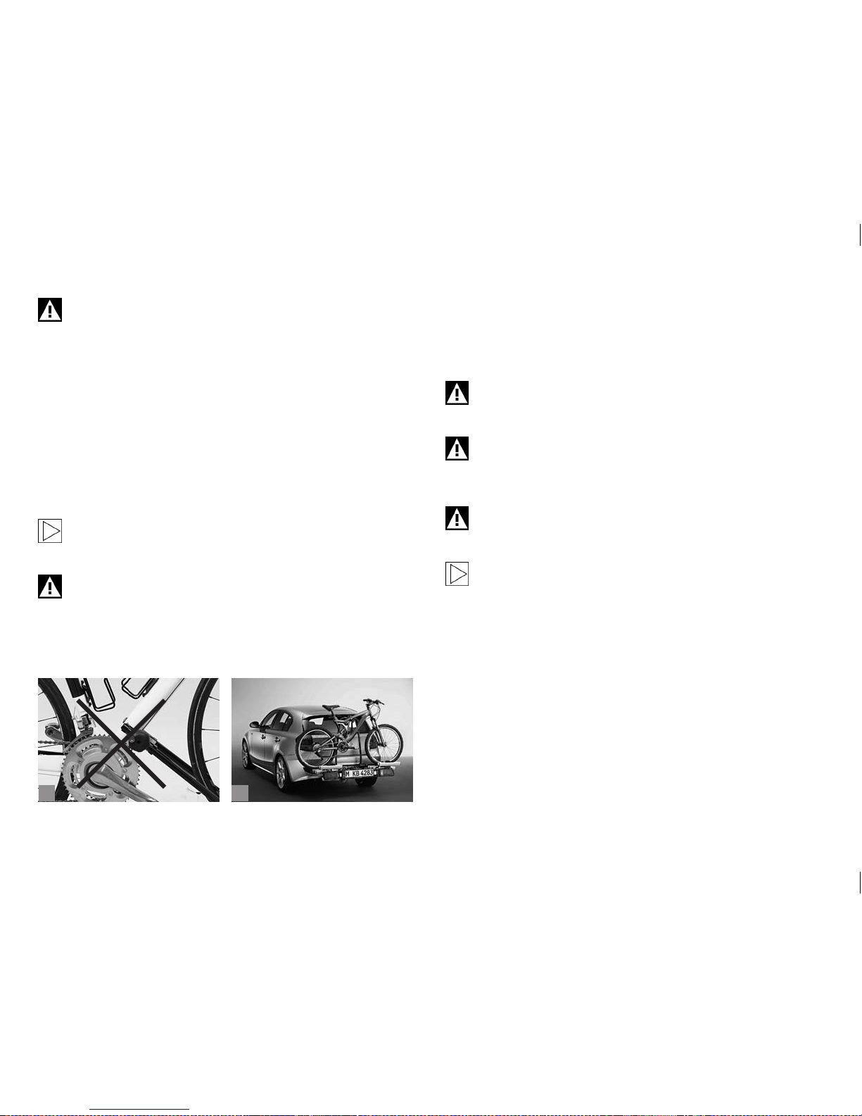
78
ba
Most clamps are potential sources of damage to large-diameter frame tubes (a) that are not designed to be xed in such
clamps!
This can result in irreparable damage to the frame. High-end, very
thin-walled aluminium frames are particularly susceptible to such kind of
damage.
Suitable, special-purpose models are, however, available at your BMW
partner.
Rear carriers (b) are becoming more and more popular. Their big advantage over roof carriers is that you do not have to lift up the bicycles so
high to attach them. Make sure the fastenings do not create any damage
to the fork or frame. Risk of breakage!
Please make sure the lights and the number plate of your car
are not hidden from view. For some carriers, a second exterior
rear view mirror is required by the road trafc regulations.
Do not buy a carrier on which the bicycle has to be mounted
upside down, i.e. with the handlebars and saddle xed face
down to the carrier. This way of fastening the bicycle exposes
handlebars, stem, saddle and seat post to extreme stress during transport. Do not opt for a carrier system with crank arm t.
Risk of breakage!
Whatever system you opt for, make sure it complies with the relevant
safety standards of your country.
Read the instructions of your bicycle carrier and observe the maximum
load capacity and recommended or prescribed driving speed.
Check whether your bicycle is properly fastened before and at
regular intervals during the ride. A bicycle that detaches from
the roof carrier may endanger other road users.
Bear in mind that your car has a greater overall height with
the bicycle on it. Measure the overall height and place a sign
stating the height somewhere in the cockpit or on the steering
wheel so that it can be easily seen.
Never transport bicycles with hydraulic brakes upside down.
This could let air enter the brake system and result in brake
failure.
If your bicycle has disc brakes, be sure to mount the safety
locks before transporting the bicycle with the wheels dismounted.
Page 83
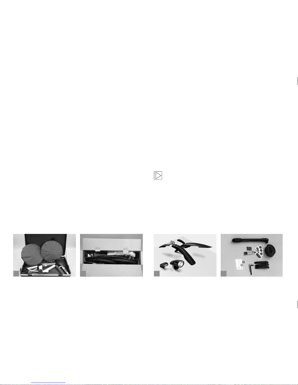
79
b
c
da
12.4 Taking the Bicycle by Plane.
If you want to take your bicycle with you when you go on a trip by plane,
pack it in an appropriate bicycle suitcase (a) or in a bicycle cardboard
box (b) that you can obtain from your BMW partner. Special bicycle bags
often do not provide sufcient protection.
Pack the wheels in special wheel bags to protect them inside the
suitcase or cardboard box. Do not forget to take the necessary tools, a
torque wrench, bits and this manual with you to be able to assemble the
bicycle and to get it ready for use at your destination.
When you remove the wheels from a bicycle with disc brakes, be sure to
place pad spacers between the brake shoes. Otherwise they can come
out unintentionally and you will have difculties in bringing them back
into position. Your BMW partner has a variety of brake pad spacers. Pull
the brake levers and x them with a tape to the handlebars. This will
keep the system free of air.
12.5 Accessories.
In purchasing this high quality bicycle you laid the foundation for many
years and miles of enjoyable cycling. Whatever you are planning to do
with your bicycle, be sure to have proper equipment and to keep a few
tips in mind. Your BMW partner has a variety of useful accessories (c) on
offer enhancing both your safety and convenience.
The most important accessories for a successful bicycle ride are a tyre
pump and a small tool kit. The tool kit should include two plastic tyre
levers, the most commonly used Allen keys, a spare inner tube, a tyre
repair kit, your mobile phone and a little cash (d). In this way you will be
well prepared in the event of a puncture or some other mishap.
Improper accessories may change the qualities of your bicycle
and even cause an accident. Therefore, before tting any
accessories do contact your BMW partner and observe the
instructions regarding the intended use of your bicycle.
BMW recommends using BMW approved parts and accessories.
Please contact a BMW ser vice centre for any inquiries regarding original
BMW parts and accessories, other BMW approved products as well as
professional advice in this respect.
Page 84
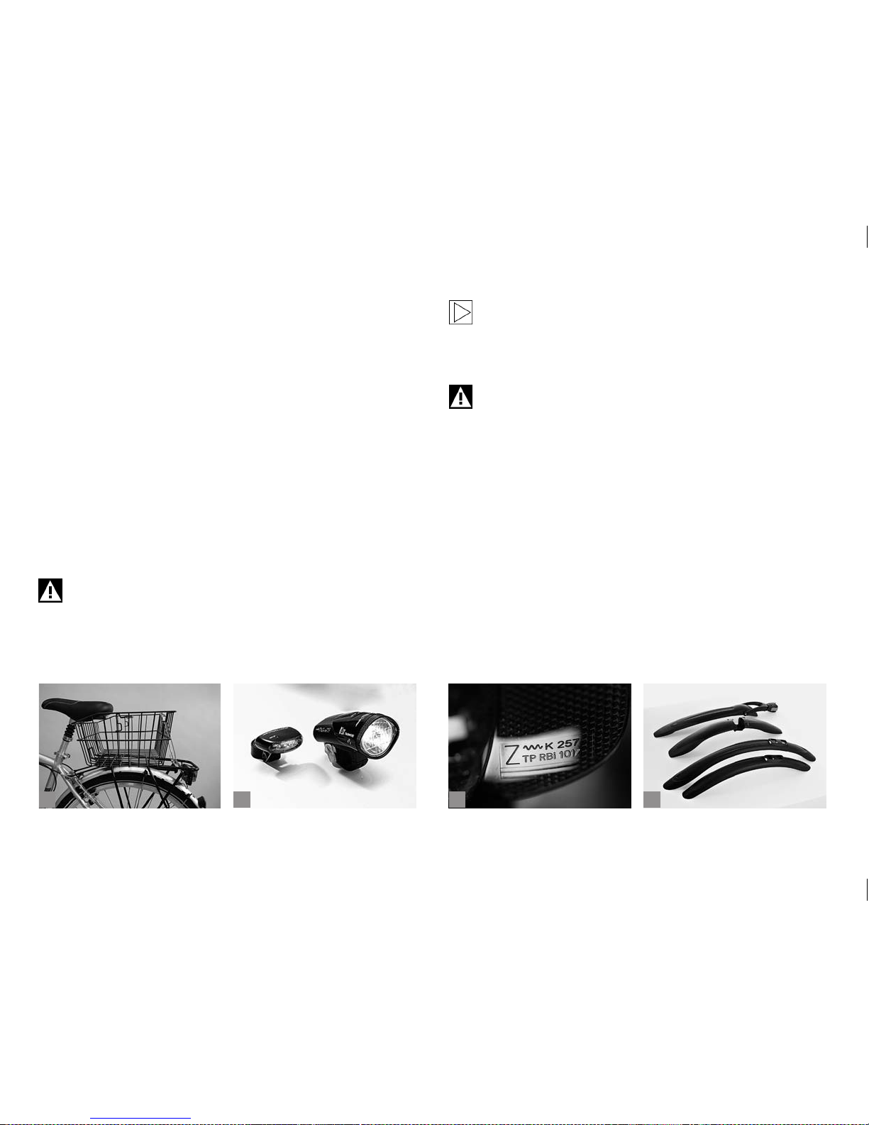
80
b
c
da
These products were tested by BMW for safety and suitability and function checked on BMW bicycles.
BMW assumes the product responsibility for them. On the other hand,
BMW refuses any liability for non approved parts or accessories of any
kind.
BMW cannot judge for each third-party product, whether it is suitable for
being assembled with BMW bicycles without safety risk. Nor can such a
guarantee be given, in the event these products have been approved by
the authorities of a countr y. Such tests do not always consider all usage
conditions for BMW bicycles and are therefore partly insufcient.
12.5.1 Additional Fittings.
Your bicycle can be tted with various kinds of accessories (a). Make
sure to observe the trafc regulations in your country. Any retrotted
part must be compatible with your bicycle. If you are in doubt or if you
have any questions, please contact your BMW partner!
Mounting incompatible parts can result in an accident!
Before buying any additional bells, horns or lighting accessories, inform yourself thoroughly whether they are permitted and
tested and accordingly approved for use on public roads. Make
sure additional batter y/accumulator-operated lamps (b) are
marked with the wavy line and the letter “K” (c).
Retrotted accessories, such as mudguards, disc or drum
brakes, pannier racks etc. can impair the functioning of your
bicycle. Ask your BMW partner for advice before mounting any
kind of accessories to your bicycle.
12.5.2 Mudguards.
If you want to t your bicycle with mudguards (d), ask your BMW partner
for advice. There are removable mudguards, also referred to as clip-on
mudguards, as well as rmly attached models that provide more protection.
Retro-ttable mudguards designed to be rmly attached are normally
made of plastic and mounted in the correct position by means of addi-
tionally tted stays. The accurate length of the stay is achieved when the
bottom edge of the mudguard runs parallel to the tyre.
Page 85
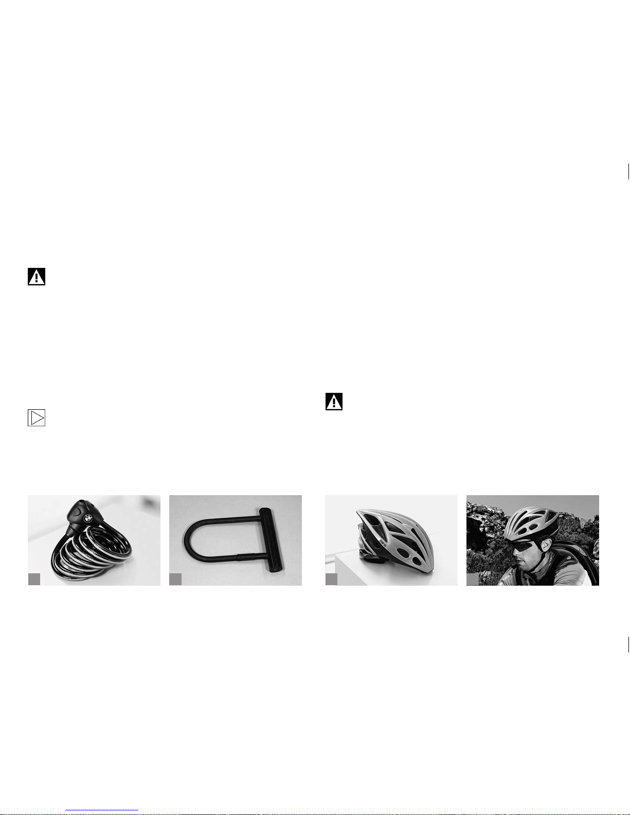
81
b
c
da
For safety reasons pop off front stays are a must. They are to prevent
the front wheel from getting jammed due to impurities clinging to the
tyre. In such an event the front stay pops off, thus avoiding a possible
accident. The plug-in connection allows an easy re-xing.
Be sure to replace damaged mudguards!
12.5.3 Bicycle Locks.
Best anti-theft protection is provided by stable cable and D-locks (a+b).
With a D-lock you can lock e.g. the bicycle frame to a lamppost, whereas
a cable lock means additional protection for the wheels. The D-lock is
mounted to the frame by means of a bracket, a convenient way of taking
it with you. Cable locks can be xed under the saddle around the tube,
if your bicycle is not tted with a frame mounting. At a bicycle specialist
shop of your trust they will be pleased to advise you about the various
security categories of bicycle locks.
Always x the lock securely to the bicycle and do not let it hang
down the handlebars.
12.6 Proper Cycling Equipment.
12.6.1 Cycling Helmets.
Cycling helmets are a must when riding a bicycle. Your BMW partner
offers an assortment of cycling helmets (c). The bicycle specialist shop
of your trust has a larger variety of styles and sizes.
Take your time when buying a helmet and keep on the one you prefer for
a while before making your nal choice. A good helmet should t snug
without pinching.
Pay attention to testing symbols indicating the helmet passed the tests
required by the DIN EN 1078 standards.
Be sure to only wear a cycling helmet during cycling. Observe the manufacturer’s instructions.
Never ride without a helmet (d)! But remember that even the
safest helmet is useless unless it ts properly and is correctly
adjusted and fastened.
Page 86
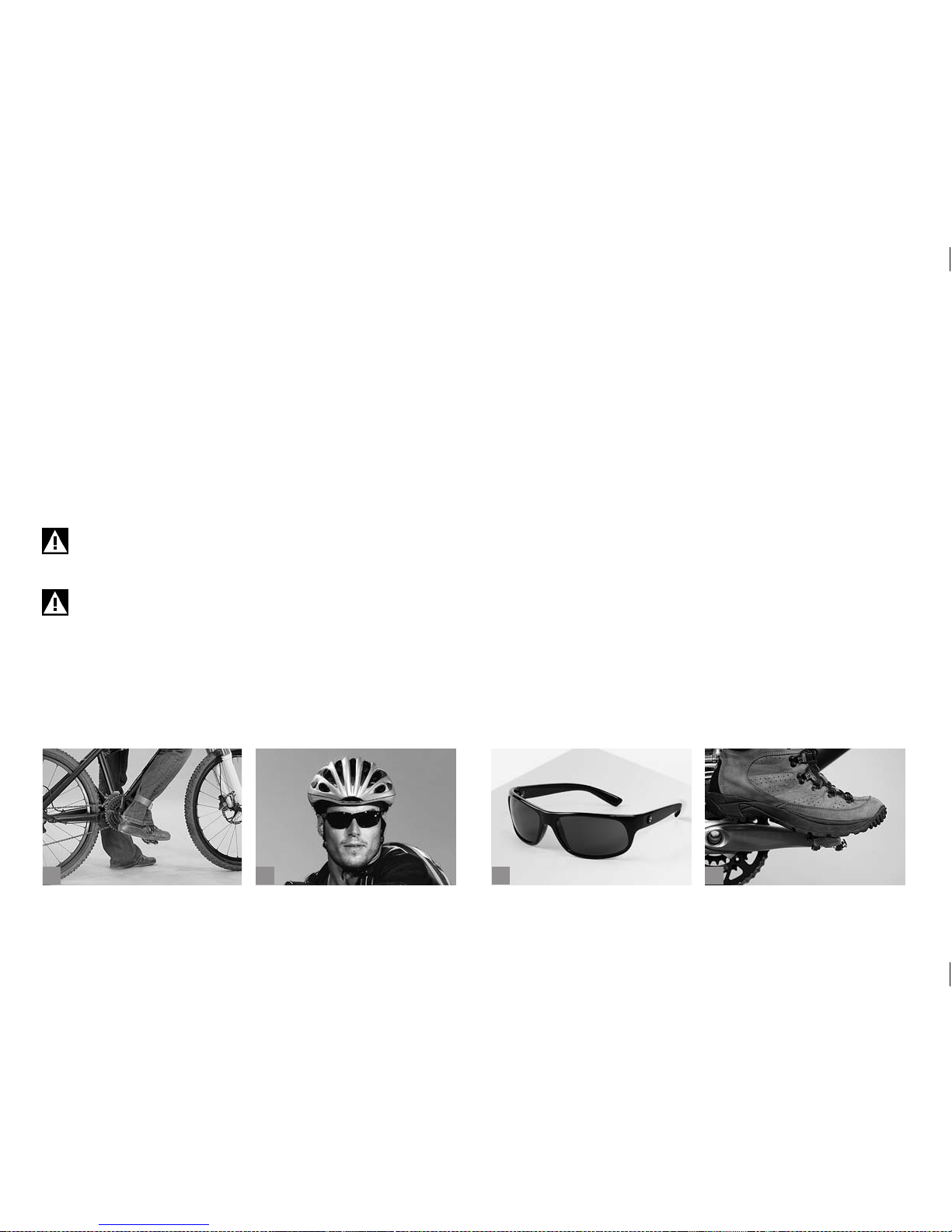
82
b
c
da
12.6.2 Proper Cycling Clothing.
Cycling pants are a must for those who appreciate sitting comfortably
in their saddle. These tight pants have a special padding in the bottom.
They are free of folds, seams and pressure that seams cause. As cycling
is certain to make you sweat, it is advisable to wear jerseys made of
synthetic material. These kinds of bres do not absorb any moisture, but
transport the sweat away from your skin to the surface of the fabric, thus
avoiding feeling chilly due to cold headwinds. Be sure to take appropriate waterproof clothing with you when you set off on a long cycling tour.
At a bicycle specialist shop of your trust they will be pleased to help you
choosing the appropriate clothing.
Never ride with wide-cut trousers or skirts that might get
caught in the spokes, chain or chainrings. To avoid any such
mishap, use suitable clips or straps, if necessary (a).
For increased visibility to other road users be sure to wear
bright-coloured clothing.
12.6.3 Cycling Glasses.
Apart from a cycling helmet and suitable clothing, cycling glasses are
absolutely essential when you set off on your bicycle (b+c).
They do not only protect your eyes from the sun and the wind, but also
keep out ies that may impede your vision when they y into your eyes.
Risk of accident!
Good cycling glasses should t tightly to your face not allowing any wind
to affect your eyes. Cycling glasses come in a wide range of models,
such as e.g. glasses with clear lenses and without UV protection for
cycling in the dawn and at night or glasses with maximum UV protection
for cycling under extreme sunlight conditions.
At a bicycle specialist shop of your trust you will nd a wide range of
cycling glasses and they will be pleased to advise you!
12.6.4 Shoes and Pedals.
Cycling shoes should be made of solid material (d) to provide rm support for your feet. In addition, they should have a stif f sole so that the
pedal cannot press through. The sole should not be too wide in the area
of the heels, as the rear stays or the crank will otherwise get in the way of
your pedalling. This will prevent your feet from assuming a natural position when pedalling and may cause knee pain in the long run.
Page 87
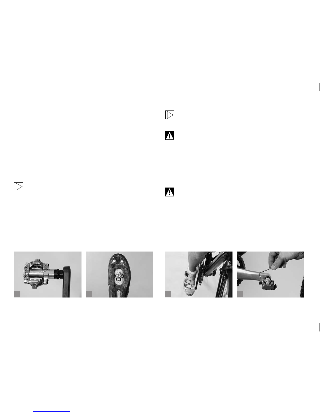
83
b
c
da
Special cycling shoes are obligatory if your cross or mountain bike is
equipped with clipless pedals (a). With these shoes small cleats are xed
to the sole (b). They give you a rm connection between shoe and pedal
and allow an acceptable walking position.
The main advantage is that these cycling shoes and clipless pedals
prevent your feet from slipping off when pedalling fast or when riding
over rough ground. They enable you not only to push but also to pull the
pedals. This makes your pedalling more uid and increases the power
transmission compared to normal pedals. With clipless pedals you can
get off the pedal very quickly. Just turn your heel to the outside. Practise
the engagement and release of clipless pedals so that you will be pre-
pared to face any difcult situation.
Read the operating instructions of the pedal manufacturers. If
you are in doubt or if you have any questions, please contact
your BMW partner!
The usual way to engage with the pedal is to turn it from the lowest
position of the crank to the horizontal using the tip of the cleat and push
down on the back of it. Normally, the shoe engages with the pedal with a
click which you will hear and feel clearly. Cleats come in different shapes,
with var ying release angles and tensions. If you are in doubt or if you
have any questions, please contact your BMW partner!
Make sure pedals and shoe soles are always clear of mud and
other impurities and grease the lock-in mechanism with lubricant at regular intervals.
Taking up the pedals, engaging and disengaging the shoes
should rst be practised while stationary. Later you can rene
your technique in a place free of trafc.
The cleat should be positioned so that the ball of your feet rests over
the pedal spindle (c). Your feet should assume a natural position when
pedalling. For most people this means that the heels will point a little
inward. Your BMW partner or the staff of a bicycle specialist shop of your
trust will be pleased to help you adjusting and mounting the pedal best
meeting your demands!
Make sure the fastening bolts of the cleats are properly tight-
ened, as you will nd it almost impossible to disengage your
shoe from the pedal, if the cleat is loose. Risk of accident!
The release force of clipless pedals is adjusted by means of an Allen
key (d). If there are any creaking or squeaking noises occurring, some
grease will solve the problem in most cases. These noises as well as
lateral play of the shoe on the pedal can, however, be also signs of wear.
Check the cleats at regular intervals.
Page 88
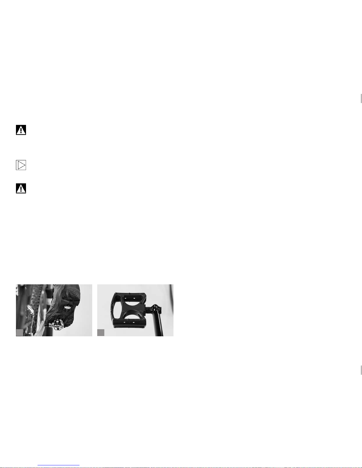
84
ba
Only use clipless pedals allowing you to engage and disengage
smoothly (a). A defective pedal or a badly worn cleat can make
the shoe disengage from the pedal. Or unclipping the shoe
from the pedal is sometimes very difcult or even impossible. In
both cases, there is the danger of an accident!
Inform yourself at a bicycle specialist shop of your trust about
the various models of cycling shoes available. Cycling shoes
come in various styles for specic uses.
Some mountain bike pedals, also referred to as platform pedals, are designed for maximum grip of the shoes when dirtbiking and freeriding (b). For this reason they have sharp edges
and/or bolted pins. As they enhance the risk of injuries during
riding, you should wear protective clothing, e.g. knee and shin
guards.
Page 89
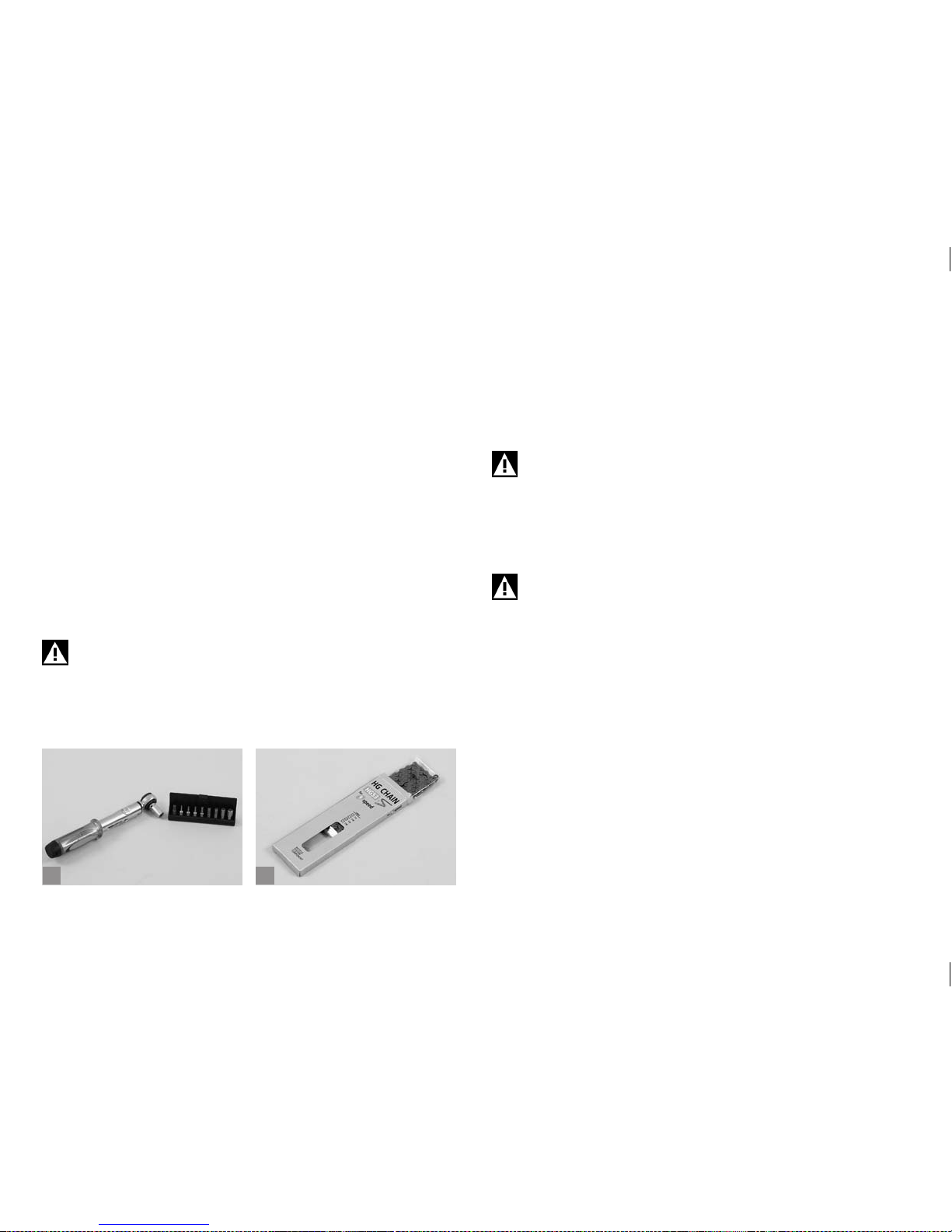
85
ba
13 GENERAL NOTES ON CARE AND
INSPECTION.
Your BMW partner will have assembled and adjusted your bicycle ready
for use when you come to collect it. Nevertheless, your bicycle needs
regular servicing. Have your BMW partner or a bicycle specialist shop of
your trust do the scheduled maintenance work. This is the only way to
ensure that all components function safely and reliably for many miles.
The bicycle will be due for its rst maintenance after 100 to 300 kilometres (60 to 180 miles), 5 to 15 hours of initial use or four to six weeks. The
bedding in phase typically involves spokes slightly losing tension, cables
stretching, gears becoming out of adjustment and bearings settling,
so there is every reason to have your dealer service the bicycle at this
stage. This bedding and settling in process is unavoidable. Therefore,
remember to make an appointment with your BMW partner for the rst
inspection of your new bicycle. The rst inspection is very important for
both functioning and durability of your bicycle.
For your own safety, bring your bicycle to your BMW partner for
its rst inspection after 100 to 300 kilometres (60 to 180 miles),
5 to 15 hours of initial use or four to six weeks, at the very latest
however after three months.
It is advisable to have your bicycle serviced regularly by your BMW
parter or at a bicycle specialist shop of your trust after the bedding in
phase. If your bicycle does harder service, because you ride a great deal
on poor road surfaces or cross-country, it will require correspondingly
shorter maintenance periods. The off-season during the winter months
is a very good time to take your bicycle to your BMW partner for the annual inspection.
Servicing and repairs are jobs best left to your BMW partner or
a bicycle specialist shop of your trust. If you have your bicycle
serviced by anyone else than an expert, you run the risk that
parts of your bicycle will fail. This may lead to an accident!
When working on your bicycle restrict yourself to jobs for which
you are equipped e.g. with a torque wrench (a) and have the
necessary knowledge.
If a component needs to be replaced, make it a rule to only use
original spare parts (b).
Page 90
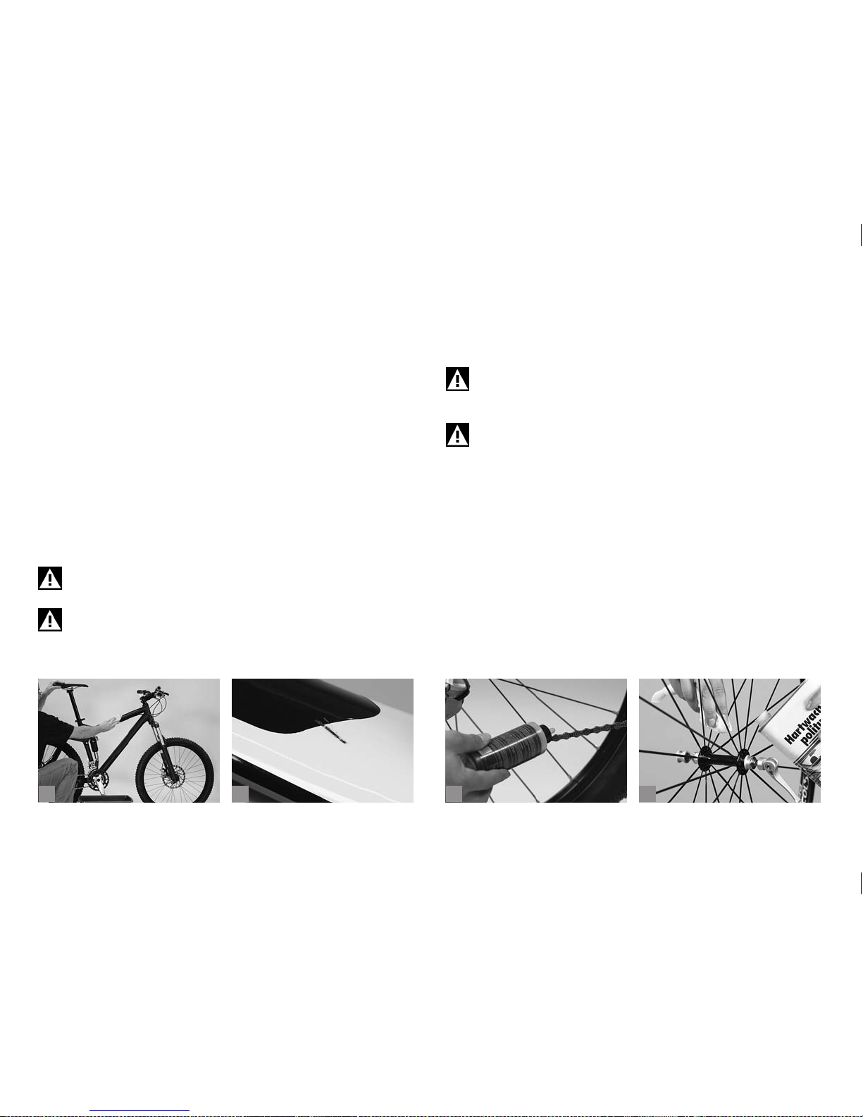
86
b
c
da
13.1 Cleaning and Caring for the Bicycle.
Dried sweat, dirt and salt from riding during the winter months can harm
your bicycle. You should therefore make it a habit of cleaning all its components at regular intervals.
Avoid cleaning your bicycle with a pressure water washer. The highpressure water ejected in a narrowly focused jet may pass through
seals and penetrate bearings. This leads to the dilution of lubricants and
consequently to greater friction. This destroys and impairs the functioning of the bearing races in the long term. Pressurized water also tends to
abrade frame stickers.
A much more gentle way of cleaning your bicycle is with a low pressure
water jet or a bucket of water and a sponge (a) or large brush. Cleaning
your bicycle by hand has another positive side-effect: you may discover
defects in the paint (b) or worn or defective components at an early
stage.
Do not clean your bicycle with a high-pressure water or steam
jet and if you do, be sure to keep it at a distance.
While cleaning, watch out for cracks, scratches, dents as well
as bent or discoloured material. Have defective components
replaced immediately and touch up paint defects. If you are in
doubt or if you have any questions, please contact your BMW
partner!
Inspect the chain after you have nished cleaning and oil it, if necessary (c) (see chapter “Chain”). Apply a coat of standard hard wax (d)
on painted and metal surfaces (except from brake sufaces). Polish the
waxed surfaces after drying to give them a nice shine.
Keep cleaning agents and chain oil clear of the brake pads,
rotors and rim sides (braking surfaces). This could impair the
functioning of the brake (see chapter ”Brake System“)!
Only use petroleum based solvents for cleaning tough oil
or grease stains from paint surfaces. Never use degreasing
agents containing acetone, methyl chloride etc., or solventcontaining, non-neutral or chemical cleaning agents that could
attack the surface!
Page 91
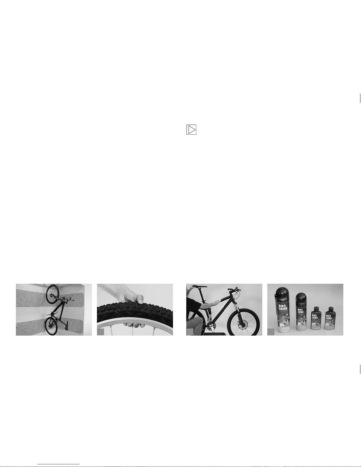
87
ba
13.2 Sheltering and Storing the Bicycle.
If you regularly service your bicycle during the year, you will not need to
take any special precautions when storing it for a short time, apart from
securing it against theft. It is advisable to store the bicycle in a dry and
airy place.
There are some things to bear in mind, when putting the bicycle away
for the winter months: Inated inner tubes tend to gradually lose air when
the bicycle is not used for a long time. If the bicycle is left standing on at
tyres for an extended period, this can cause damage to the structure of
the tyres. It is therefore better to hang the wheels or the entire bicycle
(a) or to check the tyre pressure regularly (b).
Clean the bicycle (c) and protect it against corrosion. Your BMW partner
offers a variety of care products, such as spray wax (d) etc. Take off the
seat post and allow for any moisture that may have entered to dr y away.
Spray a little nely atomized oil into the seat tube. Switch the gear to the
smallest chainring and the smallest sprocket. This relaxes the cables and
springs as much as possible.
There is usually minimal waiting time for repairs and ser vicing
at the bicycle specialist shop of your trust. What is more, many
dealers offer annual checks at a special price. Use the off-season to take your bicycle to your dealer for inspection!
c
d
Page 92
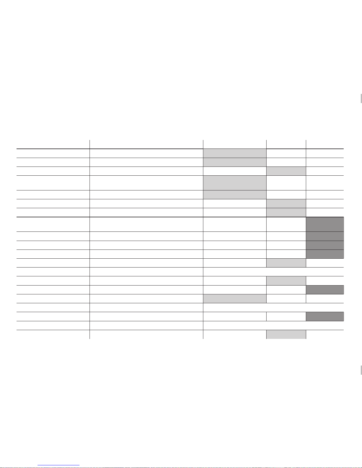
88
14 SERVICE AND MAINTENANCE SCHEDULE.
Component What to do Before every ride Monthly Annually
Lighting Check
Tyres Check pressure
Tyres Check tread and side walls
Brakes (rim-) Check lever travel, wear of brake pads, position of
pads relative to rim
Brakes (rim-) Test brakes in stationary
Brakes, (rim-), brake pads Clean
Brake cables Visual inspection
Brakes (disc-) Replace liquid
(Dot-liquids)
Suspension fork Check and retighten bolts, if necessary
Suspension fork Change oil or grease elastomers
Suspension seat post Service
Suspension seat post Check for play
Rims with rim brakes Check thickness, replace if necessary At the latest after second set of brake pads is worn down
Bottom bracket Check for play
Bottom bracket Regrease (shell)
Chain Check and grease, if necessary
Chain Check and replace, if necessar y After 800 km (620 miles)
Crankset Check and retighten, if necessary
Painted / anodised surfaces Impregnate At least every 6 months
Wheels / spokes Check for trueness and tension
Page 93
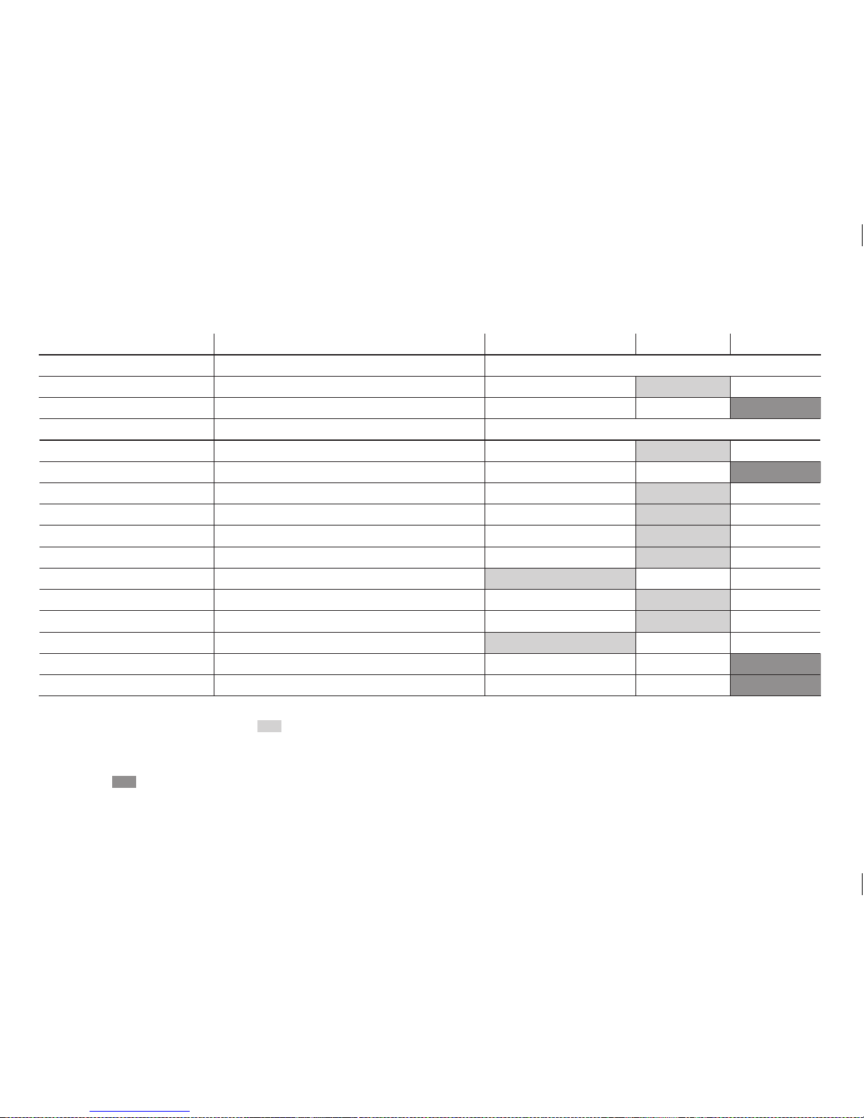
89
Component What to do Before every ride Monthly Annually
Handlebars (aluminium) Replace At the latest after 5 years
Headset Check for play
Headset Regrease
Metal surfaces Impregnate At least every 6 months
Hubs Check for play
Hubs Regrease
Pedals Check for play
Pedals (clipless) Clean and grease locking mechanism
Seat post / stem Check clamping bolts
Front / rear derailleur Clean and grease
Quick-release Check seat
Bolts and nuts Check and retighten, if necessary
Spokes Check tension
Valves Check seat
Stem / seat post Dismount and regrease
Cables gears / brakes Dismount and regrease
You should be able to do the jobs marked
yourself, provided you have a certain degree of manual skill, a little experience and suitable tools; this
includes, e.g. a torque wrench. If you come across any defects, take appropriate measures without delay. If you are in doubt or if you have any questions,
please contact your BMW partner!
Jobs marked
are best left to a bicycle specialist shop of your trust!
Page 94
90
15 RECOMMENDED TIGHTENING TORQUES.
All bolted connections of the bicycle components have to be tightened carefully and checked regularly to ensure the safe and reliable operation of the
bicycle. This is best done with a torque wrench that disengages at the desired tightening torque or a click-type torque wrench.
Tighten carefully by approaching the prescribed maximum torque in small steps (0.5 Nm increments) whilst constantly checking the proper t of the
component. Never exceed the maximum tightening torque indicated by the manufacturer! Where no maximum tightening torque is given start with 2
Nm. Observe the prescribed limit values. Follow the included instructions of the component manufacturers.
Some components have the maximum permissible tightening torque printed on them. Use a torque wrench and never exceed the maximum tightening torque! You will nd the prescribed values in the present chapter, directly on the components and/or in the manuals of the
component manufacturers.
Assembly Component Torque Nm
Rear derailleur Fastening bolt 8 - 10
Cable fastening 4 - 6
Pulleys 3 - 4
Front derailleur Front derailleur mount 5 - 7
Cable fastening 5 - 7
Shift lever Fastening bolt 6 - 8
STI brake-shift lever Fastening bolt 6 - 8
Brake lever Fastening bolt 6 - 8
Hubs Freewheel body 35 - 39
Crankset / bottom bracket Fastening bolts of squared bottom brackets 30 - 49
Fastening bolts octalink 35 - 50
Bottom bracket square-head 50 - 70
Bottom bracket Hollowtech 2 / Truvativ GXP 30 - 50
Star-shaped nut Hollowtech 2 bottom bracket 0.4 - 0.7
Allen bolts left crank arm Hollowtech 2 10 - 15
Fastening bolt left crank arm Truvativ 48 - 54
Chainring bolts 8 - 11
Pedals 30 - 40
Page 95

91
Assembly Component Torque Nm
Stems M5 bolts 5.5 - 8
M6 bolts 9 - 11
Stem for threaded forks 15
Saddle clamping M4 bolts 3 - 4
M5 bolts 5.5 - 8
M6 bolts 9 - 11
V-brakes Fastening bolt on cantilever boss 5 - 7
Fastening brake cable 6 - 8
Brake shoes 5 - 7
Clamping of swing arm bearings 5 - 6
Damper bolts 8
Drop-outs Standard 7 - 11
M3 Allen bolts 2 - 3
Bolts, in general (e.g. pannier rack
mounting, bottle cage, etc.)
M4 2.7
M5 5.5
M6 9.5
M8 23
M10 46
Wheel Wheel nuts (front wheel) 20 - 25
Wheel nuts (rear wheel) 25 - 30
Disc Brakes.
Component Magura
Torque Nm
Shimano
Torque Nm
Tektro
Torque Nm
Hayes
Torque Nm
Avid
Torque Nm
Brake calliper 6 6 - 8 8 12 8 - 10
Rotor xing 4 2 - 4 5 5 6
Brake calliper adapter 8 - 10
Brake lever 3 - 4.5
Brake lever, in general 4 - 7
Page 96
92
16 SERVICE SCHEDULE (TO BE STAMPED).
2nd Service
After 2000 kilometres (1200 miles) or 100 hours
in use or one year after date of purchase
Order no.: ........................................................................
Date: ..................................................................................
Replaced or repaired parts:
.............................................................................................
.............................................................................................
.............................................................................................
.............................................................................................
.............................................................................................
.............................................................................................
.............................................................................................
.............................................................................................
Stamp and signature
of the dealer:
3rd Service
After 4000 kilometres (2400 miles) or 200 hours
in use or one year after date of purchase
Order no.: ........................................................................
Date: ..................................................................................
Replaced or repaired parts:
.............................................................................................
.............................................................................................
.............................................................................................
.............................................................................................
.............................................................................................
.............................................................................................
.............................................................................................
.............................................................................................
Stamp and signature
of the dealer:
1
st
Service
After 300 kilometres (180 miles) or 15 hours of
use or three months after date of purchase
Order no.: ........................................................................
Date: ..................................................................................
Replaced or repaired parts:
.............................................................................................
.............................................................................................
.............................................................................................
.............................................................................................
.............................................................................................
.............................................................................................
.............................................................................................
.............................................................................................
Stamp and signature
of the dealer:
Page 97
93
4th Service
After 6000 kilometres (3700 miles) or 300 hours
of use or three years after date of purchase
Order no.: ........................................................................
Date: ..................................................................................
Replaced or repaired parts:
.............................................................................................
.............................................................................................
.............................................................................................
.............................................................................................
.............................................................................................
.............................................................................................
.............................................................................................
.............................................................................................
Stamp and signature
of the dealer:
5th Service
After 8000 kilometres (4900 miles) or 400 hours
of use or four years after date of purchase
Order no.: ........................................................................
Date: ..................................................................................
Replaced or repaired parts:
.............................................................................................
.............................................................................................
.............................................................................................
.............................................................................................
.............................................................................................
.............................................................................................
.............................................................................................
.............................................................................................
Stamp and signature
of the dealer:
6th Service
After 10000 kilometres (6200 miles) or 500 hours
of use or ve years after date of purchase
Order no.: ........................................................................
Date: ..................................................................................
Replaced or repaired parts:
.............................................................................................
.............................................................................................
.............................................................................................
.............................................................................................
.............................................................................................
.............................................................................................
.............................................................................................
.............................................................................................
Stamp and signature
of the dealer:
Page 98

94
NOTES.
Page 99

95
NOTES.
Page 100

96
NOTES.
 Loading...