

Page 1
Owner's Manual
Contents
A - Z
Online Edition for Part No. 01 41 0 012 118 - © 02/06 BMW AG
for Vehicle
The Ultimate
Driving Machine
Page 2

Online Edition for Part No. 01 41 0 012 118 - © 02/06 BMW AG
Page 3

M6
Online Edition for Part No. 01 41 0 012 118 - © 02/06 BMW AG
Owner's Manual for Vehicle
Congratulations, and thank you for choosing a BMW M6.
Thorough familiarity with your vehicle will provide you with
enhanced control and security when you drive it. We therefore
have this request:
Please take the time to read this Owner's Manual and familiarize
yourself with the information that we have compiled for you
before starting off in your new vehicle. It contains important data
and instructions intended to assist you in gaining maximum use
and satisfaction from your BMW M6's unique range of technical
features. The manual also contains information on maintenance
designed to enhance operating safety and contribute to maintaining the value of your BMW M6 throughout an extended service life.
This manual is supplemented by a Service and Warranty Information Booklet for US models or a Warranty and Service Guide
Booklet for Canadian models.
We wish you an enjoyable driving experience.
BMW AG
Page 4

© 2006 Bayerische Motoren Werke
Online Edition for Part No. 01 41 0 012 118 - © 02/06 BMW AG
Aktiengesellschaft
Munich, Germany
Reprinting, including excerpts,
only with the written consent of
BMW AG, Munich.
Order No. 01 41 0 012 118
US English II/05, 06 03 500
Printed in Germany
Printed on environmentally friendly paper,
bleached without chlorine, suitable for recycling.
Page 5

Contents
Online Edition for Part No. 01 41 0 012 118 - © 02/06 BMW AG
The fastest way to find specific topics is to use
the index, refer to page 206.
Using this Owner's Manual
4 Notes
7 Reporting safety defects
At a glance
10 Cockpit
16 iDrive
22 Voice command system
Controls
28 Opening and closing
39 Adjustments
48 Transporting children safely
50 Driving
59 Everything under control
70 Technology for comfort, convenience
and safety
80 Lamps
84 Climate
90 Practical interior accessories
Driving tips
98 Things to remember when driving
Mobility
168 Refueling
170 Wheels and tires
175 Under the hood
180 Maintenance
182 Replacing components
191 Giving and receiving assistance
Reference
198 Technical data
201 Short commands of voice command
system
206 Everything from A to Z
Navigation
106 Starting navigation system
107 Destination entry
118 Destination guidance
123 What to do if …
Entertainment
126 On/off and tone
130 Radio
139 CD player and CD changer
Communications
148 Telephoning
161 TeleService, BMW Assist
Reference At a glanceControlsDriving tipsCommunications NavigationEntertainmentMobility
Page 6

Notes
Online Edition for Part No. 01 41 0 012 118 - © 02/06 BMW AG
Using this Owner's Manual
Notes
We have made every effort to ensure that you
are able to find what you need in this Owner's
Manual as quickly as possible. The fastest way
to find specific topics is to use the detailed
index at the back of the manual. If you wish to
gain an initial overview of your vehicle, you will
find this in the first chapter.
Should you want to sell your BMW some day,
please remember to hand over the Owner's
Manual as well; it is an important component of
your vehicle.
Additional sources of information
Should you have any other questions, your
BMW center will be glad to advise you at any
time.
You can find information on BMW, e.g. technology, on the Internet at www.bmwusa.com.
Symbols used
Indicates precautions that must be fol-
lowed precisely in order to avoid the possibility of personal injury and serious damage to
the vehicle.
Indicates information that will assist you
in gaining the optimum benefit from your
vehicle and enable you to care more effectively
for your vehicle.
Refers to measures that can be taken to
help protect the environment.
< Marks the end of a specific item of informa-
tion.
*
Indicates special equipment, country-specific equipment and optional extras, as well as
equipment and functions not yet available at the
time of printing.
"..." Identifies Control Display texts used to
select individual functions.
{...} Verbal instructions to use with the voice
command system.
{{...}} Identifies the answers generated by the
voice command system.
4
Symbols on vehicle components
Indicates that you should consult the relevant section of this Owner's Manual for
information on a particular part or assembly.
Page 7

The individual vehicle
Online Edition for Part No. 01 41 0 012 118 - © 02/06 BMW AG
When purchasing your BMW, you have decided
in favor of a model with individualized equipment and features. This Owner's Manual
describes all equipment offered for the
BMW M6.
Please bear in mind that the manual may contain information on accessories and equipment
that you have not specified for your own vehicle.
Sections describing options and special equip-
*
ment are marked by asterisks
identifying possible differences between the
descriptions in this manual and your own vehicle's equipment.
If equipment in your BMW is not described in
this Owner's Manual, please refer to the accompanying Supplementary Owner's Manuals.
to assist you in
Editorial notice
BMW pursues a policy of continuous, ongoing
development that is conceived to ensure that
our vehicles continue to embody the highest
quality and safety standards combined with
advanced, state-of-the-art technology. In isolated cases it is possible that the features
described in this Owner's Manual could differ
from those on your vehicle.
5
Reference At a glanceControlsDriving tipsCommunications NavigationEntertainmentMobility
Page 8

For your own safety
Online Edition for Part No. 01 41 0 012 118 - © 02/06 BMW AG
Maintenance and repairs
Notes
Advanced technology, e.g. the use of
modern materials and high-performance
electronics, requires specially adapted maintenance and repair methods. Have corresponding
work on your BMW performed only by your
BMW center or a workshop that works according to BMW repair procedures with appropriately trained personnel. If this work is not
carried out properly, there is a danger of subsequent damage and related safety hazards.<
California Proposition 65 Warning
California law requires us to issue the following
warning:
Engine exhaust and a wide variety of
automobile components and parts,
including components found in the interior furnishings in a vehicle, contain or emit chemicals
known to the State of California to cause cancer
and birth defects and reproductive harm. In
addition, certain fluids contained in vehicles and
certain products of component wear contain or
emit chemicals known to the State of California
to cause cancer and birth defects or other
reproductive harm.
Battery posts, terminals and related accessories contain lead and lead compounds. Wash
your hands after handling.
Used engine oil contains chemicals that have
caused cancer in laboratory animals. Always
protect your skin by washing thoroughly with
soap and water.<
Parts and accessories
For your own safety, use genuine parts
and accessories approved by BMW.
When you purchase accessories tested and
approved by BMW and Genuine BMW Parts,
you simultaneously acquire the assurance that
they have been thoroughly tested by BMW to
ensure optimum performance when installed
on your vehicle.
BMW warrants these parts to be free from
defects in material and workmanship.
BMW will not accept any liability for damage
resulting from installation of parts and accessories not approved by BMW.
BMW cannot test every product made by other
manufacturers to verify if it can be used on a
BMW safely and without risk to either the vehicle, its operation, or its occupants.
Genuine BMW Parts, BMW Accessories and
other products approved by BMW, together
with professional advice on using these items,
are available from all BMW centers.
Installation and operation of non-BMW
approved accessories such as alarms, radios,
amplifiers, radar detectors, wheels, suspension
components, brake dust shields, telephones,
including operation of any mobile phone from
within the vehicle without using an externally
mounted antenna, or transceiver equipment, for
instance, CBs, walkie-talkies, ham radios or
similar accessories, may cause extensive damage to the vehicle, compromise its safety, interfere with the vehicle's electrical system or affect
the validity of the BMW Limited Warranty. See
your BMW center for additional information.<
Maintenance, replacement, or repair of
the emission control devices and systems may be performed by any automotive
repair establishment or individual using any certified automotive part.<
6
Page 9

Service and warranty
Online Edition for Part No. 01 41 0 012 118 - © 02/06 BMW AG
We recommend that you read this publication
thoroughly.
Your BMW is covered by the following warranties:
> New Vehicle Limited Warranty
> Rust Perforation Limited Warranty
> Federal Emissions System Defect Warranty
> Federal Emissions Performance Warranty
> California Emission Control System Limited
Warranty
Detailed information about these warranties is
listed in the Service and Warranty Information
Booklet for US models or in the Warranty and
Service Guide Booklet for Canadian models.
Reporting safety defects
For U.S. customers
The following applies only to vehicles owned
and operated in the US.
If you believe that your vehicle has a defect
which could cause a crash or could cause injury
or death, you should immediately inform the
National Highway Traffic Safety Administration
(NHTSA) in addition to notifying BMW of North
America, LLC, P.O. Box 1227, Westwood, New
Jersey 07675-1227, Telephone (800) 831-
1117.
If NHTSA receives similar complaints, it may
open an investigation, and if it finds that a safety
defect exists in a group of vehicles, it may order
a recall and remedy campaign. However,
NHTSA cannot become involved in individual
problems between you and your dealer or
BMW of North America, LLC.
To contact NHTSA, you may call the Vehicle
Safety Hotline toll-free at 1-800-327-4236
(TTY: 1-800-424-9153); go to
http://www.safercar.gov; or write to: Administrator, NHTSA, 400 Seventh Street, SW.,
Washington, DC 20590. You can also obtain
other information about motor vehicle safety
from http://www.safercar.gov
For Canadian customers
Canadian customers who wish to report a
safety-related defect to Transport Canada,
Defect Investigations and Recalls, may telephone the toll free hotline 1-800-333-0510,
or contact Transport Canada by mail at: Transport Canada, ASFAD, Place de Ville Tower C,
330 Sparks Street, Ottawa ON K1A 0N5.
7
Reference At a glanceControlsDriving tipsCommunications NavigationEntertainmentMobility
Page 10
Online Edition for Part No. 01 41 0 012 118 - © 02/06 BMW AG
Page 11

At a glance
Online Edition for Part No. 01 41 0 012 118 - © 02/06 BMW AG
At a glance
This overview of buttons, switches and displays
is intended to familiarize you with your vehicle's
operating environment. The section will also
assist you in becoming acquainted with the
control concepts and options available for
operating the various systems.
Page 12
Cockpit
Online Edition for Part No. 01 41 0 012 118 - © 02/06 BMW AG
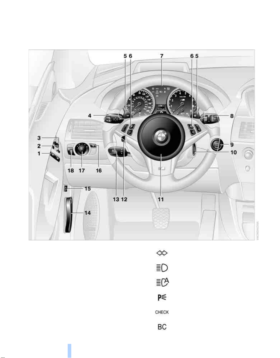
Around the steering wheel: controls and displays
Cockpit
1 Opening and closing windows 37
2 Folding exterior mirrors in and out
3 Adjusting exterior mirrors 43
Automatic parking function 44
10
*
43
4
Turn signals 56
High beams, headlamp flasher 81
High-beam assistant
Roadside parking lamps 81
Check Control 64
Computer 60
*
81
Page 13
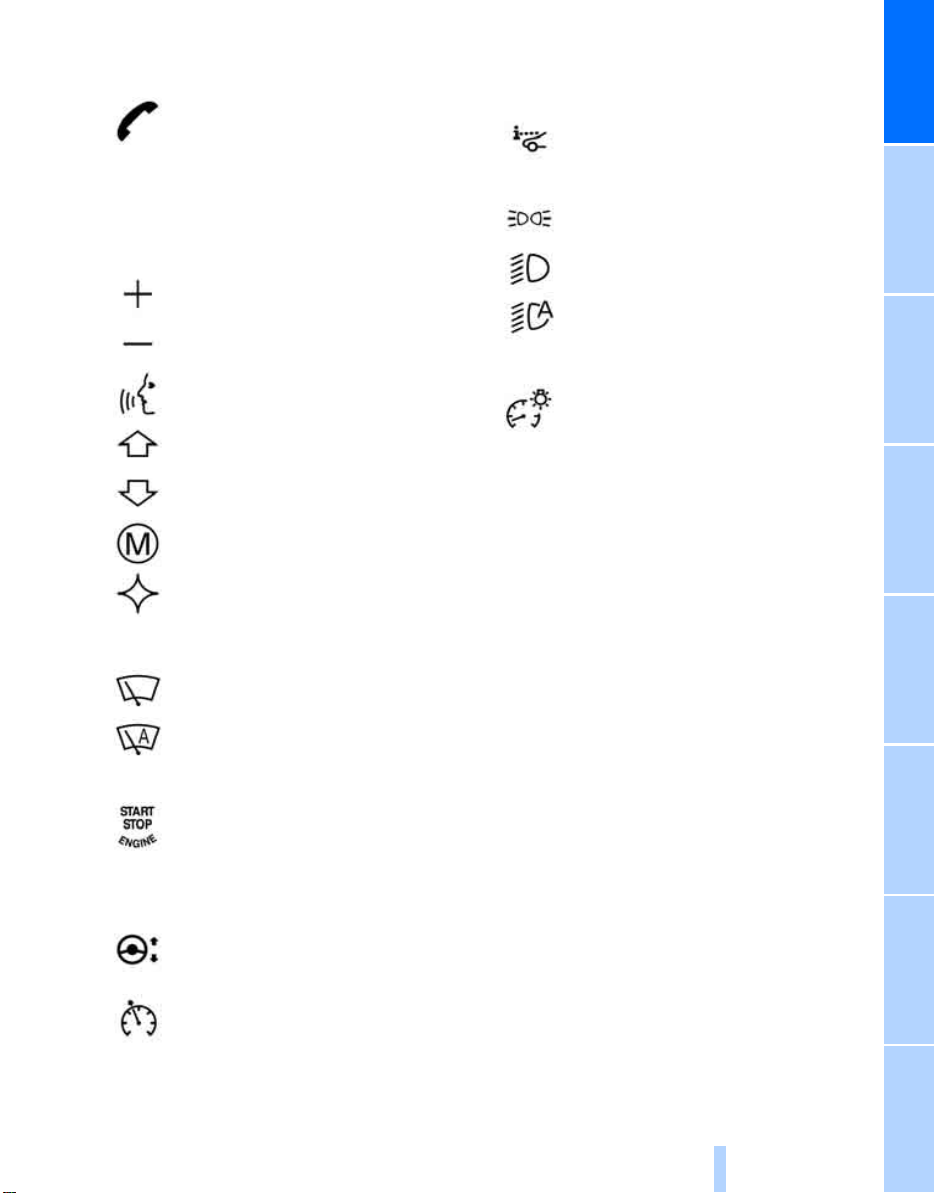
5 Shift paddles 54
Online Edition for Part No. 01 41 0 012 118 - © 02/06 BMW AG
6 Buttons on steering wheel
Mobile phone
> Press: accepting and ending
call, starting dialing
selected phone number and
redialing if no phone number is
selected
> Press longer: redialing
Volume
*
148
14 Releasing hood 175
15 Opening luggage compartment lid 33
16
*
for
17
Head-Up Display
Parking lamps 80
Low beams 80
Automatic headlamp control 80
Adaptive Head Light
High-beam assistant
*
77
*
81
*
81
At a glance
Activating/deactivating voice
command system
Changing radio station
Selecting music track
Scrolling in phone book and in lists
with stored phone numbers
MDrive, call up individual
settings 46
Individually programmable 45
7 Instrument cluster 12
8
9
10 Ignition lock 50
11 Horn: entire surface
12
Windshield wipers 56
Rain sensor 57
Starting/stopping engine and
switching ignition on/off 50
Steering wheel adjustment 44
*
22
18
Instrument lighting 83
13
Cruise control 57
11
Reference ControlsDriving tipsCommunications NavigationEntertainmentMobility
Page 14
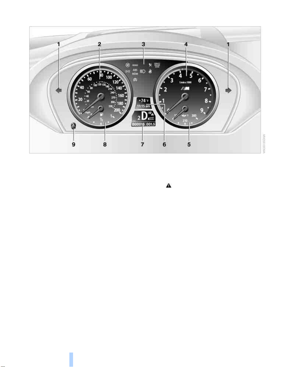
Instrument cluster
Online Edition for Part No. 01 41 0 012 118 - © 02/06 BMW AG
Cockpit
1 Indicator lamps for turn signals
2 Speedometer
3 Indicator and warning lamps 13
4 Tachometer 59
5 Engine oil thermometer 60
6 Display for
> Computer 60
Engine oil level 176
> Indicator and warning lamps 64
> Speed of cruise control 58
7 Displays for
> Sequential Manual Transmission with
Drivelogic 53
> Check Control message present 64
> Odometer and trip odometer 59
> Date and remaining distance to be
driven for service requirements 63
> High-beam assistant
8 Fuel gauge 60
9 Resetting trip odometer 59
*
82
12
Page 15
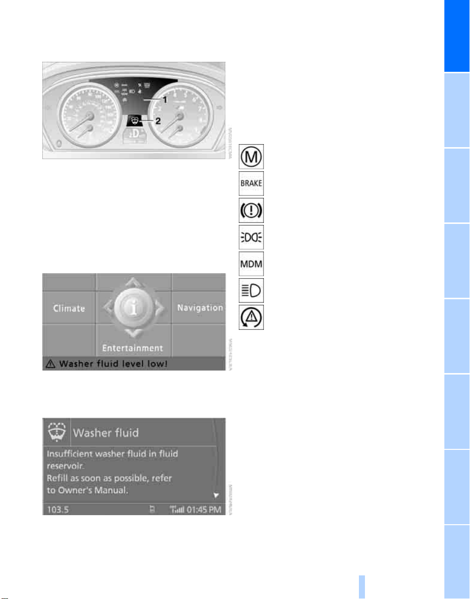
Indicator and warning lamps
Online Edition for Part No. 01 41 0 012 118 - © 02/06 BMW AG
The concept
function or the appropriate actions to take, refer
to page 64.
In cases of corresponding urgency, this information is immediately displayed when the
associated lamps light up.
Indicator lamps without text messages
The following indicator lamps in the display
area 1 indicate that the associated functions are
activated or deactivated:
MDrive 46
At a glance
Indicator and warning lamps can light up both in
the display area 1 and in the display 2 in various
combinations and colors.
When the engine is started or the ignition is
switched on, some lamps are checked for
proper operation and light up briefly in the process.
Explanatory text messages
Text messages at the bottom edge of the Control Display explain the meaning of the indicator
and warning lamps displayed.
Handbrake set 52
Handbrake engaged for Canadian
models
Parking lamps/low beams 80
M Dynamic Mode 72
High beams/headlamp flasher 81
Lamp flashes:
DSC controls the drive and braking
forces for maintaining vehicle
stability 72
You can consult Check Control for additional
information, e.g. regarding the cause of a mal-
13
Reference ControlsDriving tipsCommunications NavigationEntertainmentMobility
Page 16
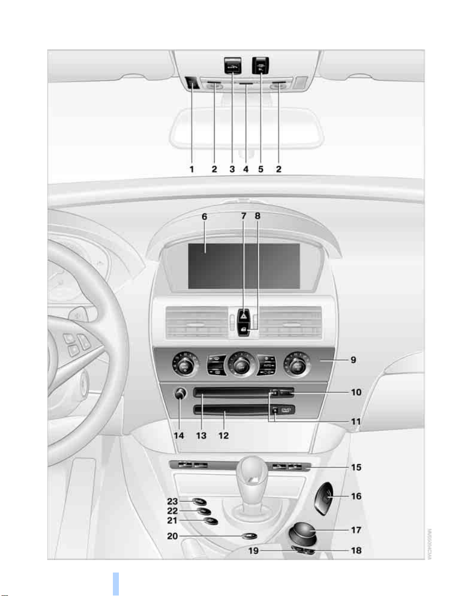
Around the center console: controls and displays
Online Edition for Part No. 01 41 0 012 118 - © 02/06 BMW AG
Cockpit
14
Page 17
1 Microphone for handsfree mode for
Online Edition for Part No. 01 41 0 012 118 - © 02/06 BMW AG
telephone
and for voice command system*22
2 Reading lamps 83
3 Initiating
4 Interior lamps 83
5 Indicator lamp
airbags 76
6 Control Display 16
7 Hazard warning flashers
8 Central locking system 32
9 Automatic climate control 84
*
an emergency call 191
for front passenger
Temperature setting, left/right 84
Automatic air distribution and
volume 85
Cooling function 86
AUC Automatic recirculated-air
control 87
Recirculated-air mode 87
Maximum cooling 86
13 Drive for audio CDs 126
14 Entertainment sound output on/off
and adjusting volume 126
15
16 Bracket for cup holder 93
17 Controller 16
Turn, press or move horizontally in four
directions
18 Activating voice command system
19 Opening start menu on Control Display 17
20 Drivelogic of Sequential Manual
Transmission 54
21 EDC Electronic Damping Control 73
22 DSC Dynamic Stability Control 71
23 M Engine Dynamic Control POWER 55
Heated seats 43
PDC Park Distance Control
Flat Tire Monitor 73
*
70
*
22
At a glance
Residual heat mode 87
Switching off automatic climate
control 87
Air volume 86
Defrosting windows and removing
condensation 86
Rear window defroster 84
10 Changing
> radio station 126
> track 126
11 Ejecting
> navigation DVD
> audio CD 126
12 Player for navigation DVD in Professional
navigation system 106
*
106
*
15
Reference ControlsDriving tipsCommunications NavigationEntertainmentMobility
Page 18
iDrive
Online Edition for Part No. 01 41 0 012 118 - © 02/06 BMW AG
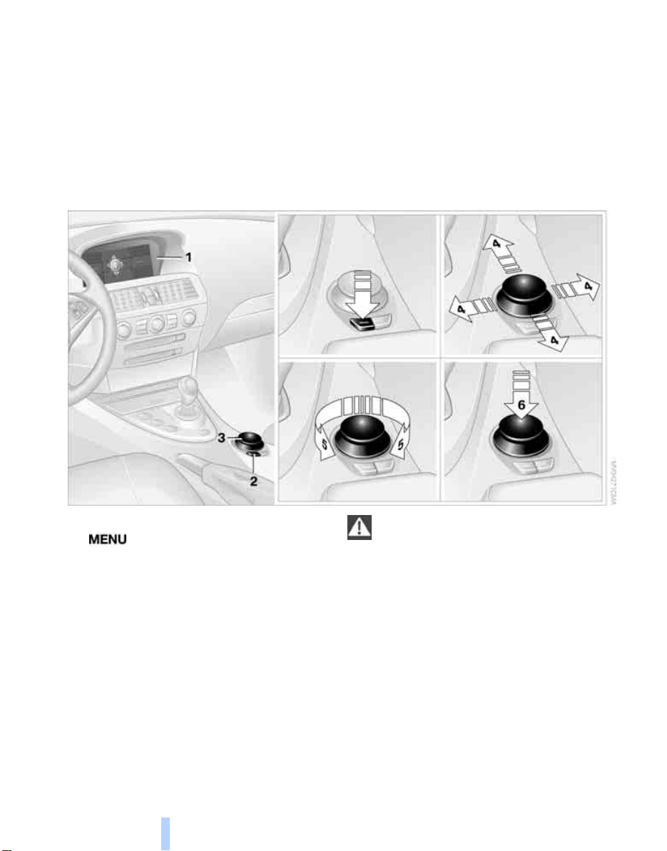
iDrive combines the functions of a multitude of
iDrive
switches. This allows these functions to be
operated from a central position. The following
section provides an introduction to basic menu
Controls
navigation. The control of individual functions is
described in connection with the relevant
equipment.
1 Control Display
2 button
Opening the start menu
3 Controller
You can use the controller to select menu
items and change settings by:
> moving in four directions, arrows 4
> turning, arrow 5
> pressing, arrow 6
16
To avoid becoming distracted and unnec-
essarily endangering both your own vehicle's occupants and other road users, never
attempt to use the controls or make entries
unless traffic and road conditions allow.<
Page 19
Menu overview
Online Edition for Part No. 01 41 0 012 118 - © 02/06 BMW AG
Communication
> Telephone
> BMW Assist* or TeleService
Navigation or onboard information
> Navigation system
> Onboard info, e.g. for displaying of the
average fuel consumption
Entertainment
> Radio
> CD player and CD changer
Climate
> Air distribution
> Automatic program
> Parked car ventilation
menu
> Switching off the Control Display
> Tone and display settings
> Settings for your vehicle, e.g. for MDrive, or
settings for the central locking system
> Display of service requirements and dates
for statutory emission and vehicle inspections
> Settings for the telephone
*
*
*
*
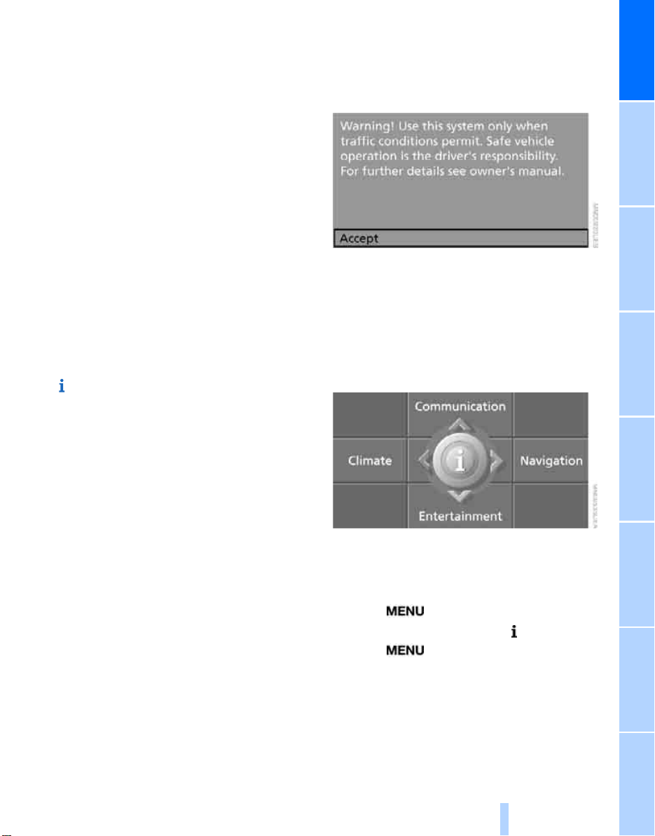
Basic operation
From radio readiness, refer to page 50, the following message is shown on the Control Display:
To clear the message:
Press the controller.
This displays the start menu.
On vehicles with a single drive, the message
automatically disappears after approx. 10 seconds.
Start menu
You can call up all the functions of iDrive using
five menu items.
At a glance
Opening start menu
Press the button.
To open the start menu from the menu:
Press the button twice.
17
Reference ControlsDriving tipsCommunications NavigationEntertainmentMobility
Page 20
Opening menu items of start menu
Online Edition for Part No. 01 41 0 012 118 - © 02/06 BMW AG
iDrive
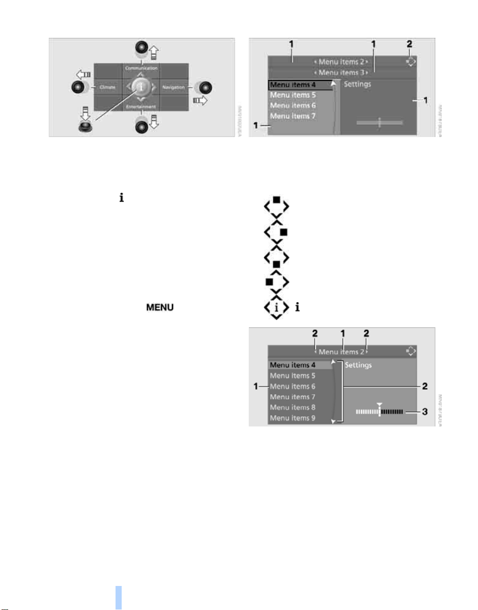
Displays in menu
From the start menu, you can call up the four
menu items Communication, Navigation, Entertainment, and Climate by moving the controller
left, right, forward, or back.
You can open the menu by pressing the controller.
Comfort opening of menu items
Convenience opening offers you the option of:
> Opening a menu item of the start menu in
the view last selected
> Direct switching between Communication,
Navigation, Entertainment and Climate
without pressing the button
To do so, move the controller in the corresponding direction and hold it for longer than
approx. 2 seconds.
1 Each menu is divided into fields. The cur-
rently selected field appears brighter.
2 A symbol indicates the last selected menu
item of the start menu:
Communication
Navigation or onboard info
Entertainment
Climate
menu
1 Menu items are usually grouped in horizon-
tal or vertical lists.
2 Arrows indicate the possibility of accessing
other menu items that are not currently visible.
3 Settings are displayed graphically or
numerically.
18
Page 21
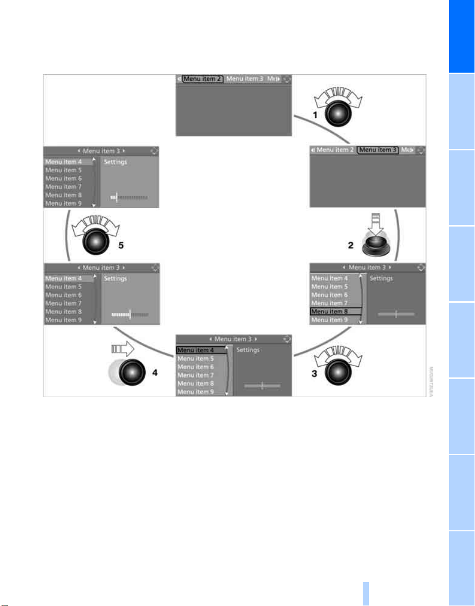
Operating principle at a glance
Online Edition for Part No. 01 41 0 012 118 - © 02/06 BMW AG
Basic operation via iDrive is described in this
view.
You can view the individual steps under Settings on Control Display, Setting time, refer to
page 68.
At a glance
1 Selecting menu item:
> Turn controller; marking moves
> Menu items shown in white can be
selected by marking
2 Activating a menu item:
> Press controller
> New menu items are displayed or
function is carried out
3 Selecting a menu item: refer to 1
4 Changing between fields:
> Briefly move controller left, right, forward
or back
> Release controller
> Active field appears lighter
5 Adjusting settings:
> Turn controller
> Graphic display, numerical value or text
displays can be changed
> Confirmation by changing field
19
Reference ControlsDriving tipsCommunications NavigationEntertainmentMobility
Page 22
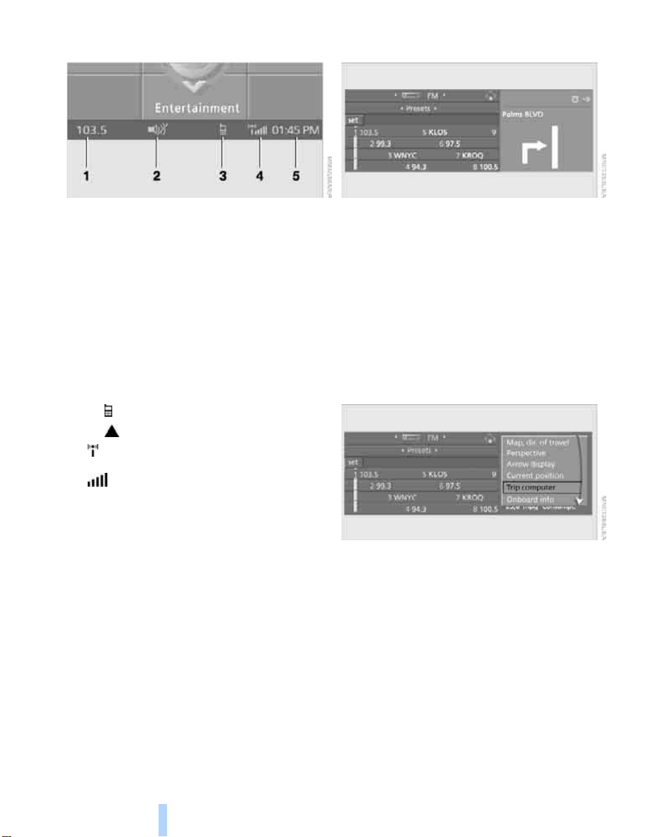
Status information
Online Edition for Part No. 01 41 0 012 118 - © 02/06 BMW AG
iDrive
Assistance window*
1 Display for:
> Entertainment:
Radio, CD
> Telephone
Name of linked mobile phone, network
search or no network
> "BMW Assist"
Existing voice connection with a service
from BMW Assist
2 Entertainment sound output off
3 Display for:
> New entries present in "Missed calls"
> Roaming active
4 Telephoning
phone is logged-on in the vehicle
Mobile phone network reception
strength, display dependent on mobile
phone
5 Time
Other displays:
When Check Control information appears or
entries are made via the voice command system*, the status information is temporarily hidden.
*
in "Communication":
*
:
*
possible if the mobile
Additional information can be displayed in the
assistance window:
> the computer or the trip computer
> the arrow or map view with a navigation
system
*
> the current position
Selecting displays
1. Move the controller to the right to switch to
the assistance window and press the controller.
*
2. Select a menu item.
3. Press the controller.
20
Page 23
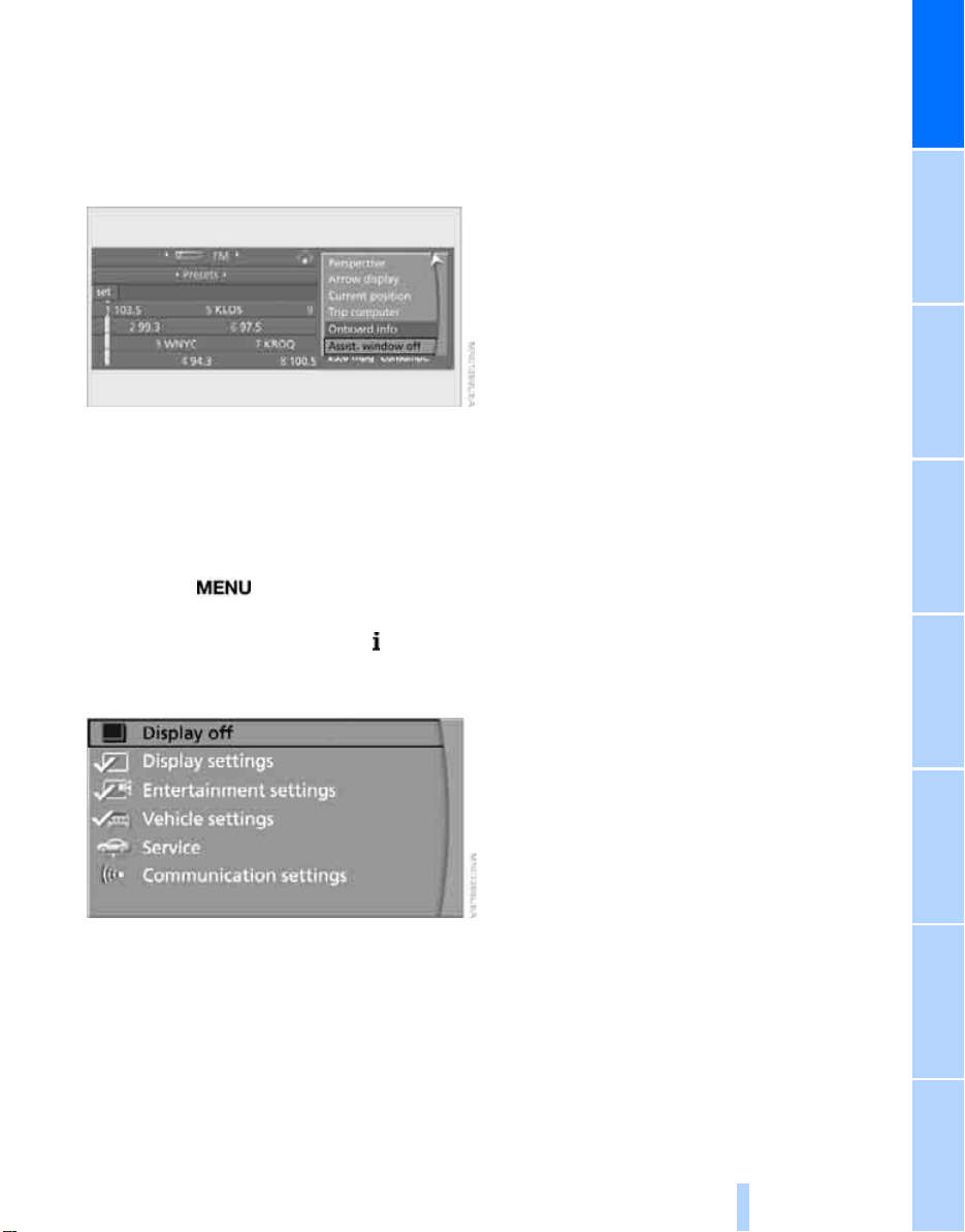
Switching assistance window on/off
Online Edition for Part No. 01 41 0 012 118 - © 02/06 BMW AG
1. Move the controller to the right to switch to
the assistance window and press the controller.
2. Select "Assist. window off" and press the
controller.
To switch on, change to the assistance window
and press the controller.
Switching Control Display on/ off
1. Press the button.
This opens the start menu.
2. Press the controller to open the menu.
3. Select "Display off" and press the control-
ler.
At a glance
To switch on, press the controller.
21
Reference ControlsDriving tipsCommunications NavigationEntertainmentMobility
Page 24
Voice command system
Online Edition for Part No. 01 41 0 012 118 - © 02/06 BMW AG
*
The concept
The voice command system allows you to control operation of various vehicle systems without ever removing your hands from the steering
wheel.
Individual menu items on the Control Display
can be spoken as commands. This frees you of
having to use the controller.
The voice command system transforms your
spoken commands into control signals for the
selected systems and provides support in the
form of instructions or questions.
The voice command system includes a special
microphone.
Voice command system
The microphone is located near the interior
rearview mirror, refer to page 14.
Prerequisite
In order to enable identification of the commands to be spoken, use iDrive to set the language for the voice command system. Setting
iDrive language, refer to page 69.
Symbols in Owner's Manual
Voice commands
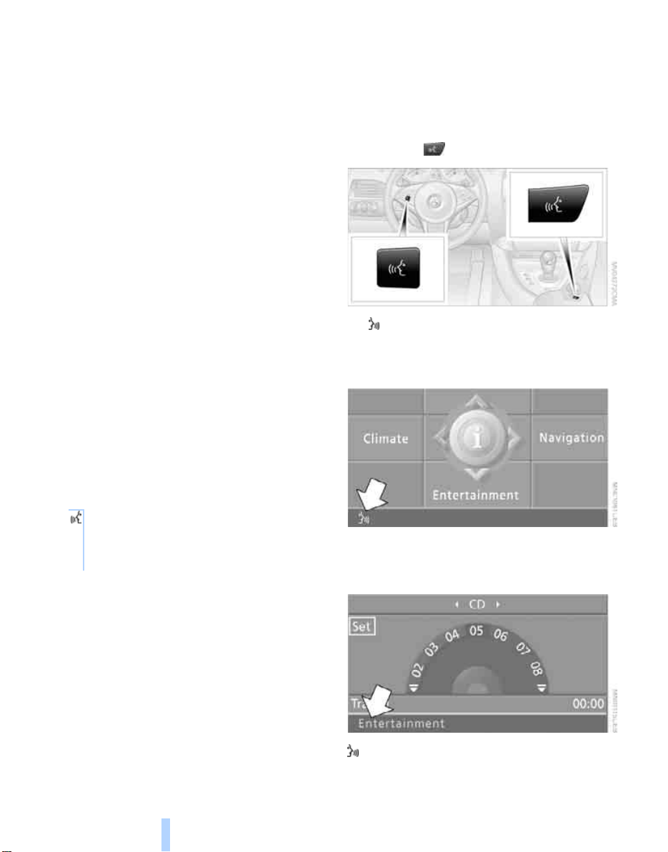
Activating voice command system
1. Press the button.
This symbol on the Control Display and
an acoustic signal tell you that the voice
command system can respond to commands.
{...} Say the specified commands word for
word.
{{...}} Indicates the responses of the voice
command system.
22
2. Say the command.
The command is displayed on the Control
Display.
This symbol is shown on the Control Display
when you can input additional commands.
Page 25
If no other commands are possible, then oper-
Online Edition for Part No. 01 41 0 012 118 - © 02/06 BMW AG
ate the equipment using iDrive.
Terminating or canceling voice input
Press the button on the steering wheel or in
the center console
or
{Cancel}
Commands
Having possible commands read aloud
You can have the system read aloud the possible commands related to the selected menu
item on the Control Display.
To have the system list the possible commands:
{Options}
For example, if you have selected "CD", the
system will read aloud the possible commands
for operating the CD player and the CD
*
changer
.
Opening help
{Help}
An example: selecting a track
1. Switch on Entertainment sound output if
necessary.
2. Press the button on the steering wheel
or in the center console.
3. {Entertainment}
The system says:
{{Entertainment}}
4. {CD}
The system says:
{{CD player switched on}}
At a glance
Using alternative commands
There are often several commands for running
a function, e.g.:
{Radio on} or {Turn radio on}
Running functions directly with short
commands
You can use short commands to carry out certain functions directly, regardless of which
menu item is selected, refer to page 201.
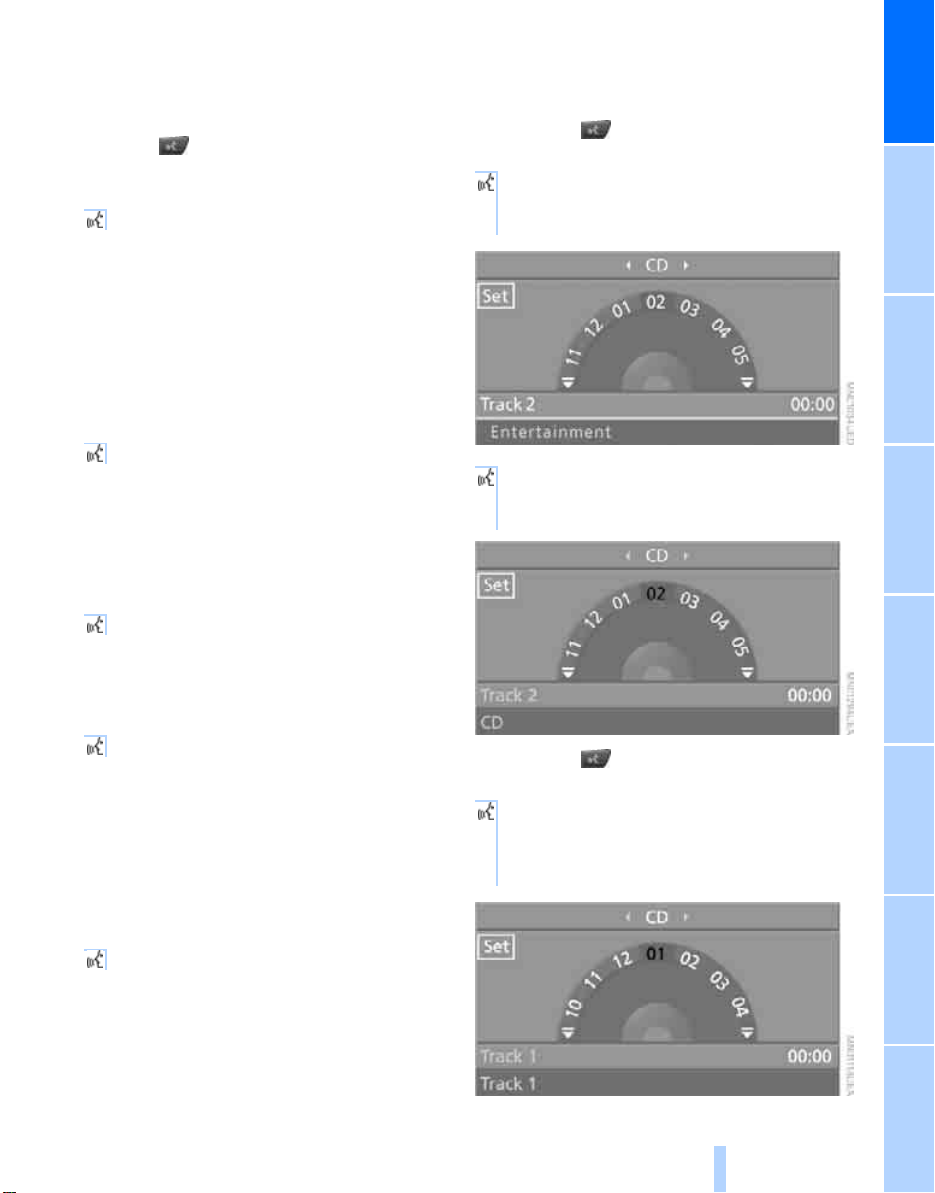
Opening start menu
{Main menu}
5. Press the button on the steering wheel
or in the center console.
6. Select a track, e.g.:
{Track 1}
The system says:
{{Track 1}}
23
Reference ControlsDriving tipsCommunications NavigationEntertainmentMobility
Page 26

Notes
Online Edition for Part No. 01 41 0 012 118 - © 02/06 BMW AG
The mobile phone can also be operated
with voice commands, refer to
page 156.<
For voice commands, bear the following in
mind:
> Say the commands and numbers smoothly
and at normal volume, avoiding excessive
emphasis and pauses. This also applies to
spelling when entering the destination.
> Always say the commands in the language
of voice command system.
> When selecting a radio station, use the
usual pronunciation of the station name.
> For entries in the voice-activated phone
book, only use names in the language of the
Voice command system
voice command system and no abbreviations.
> Keep the doors and windows closed to pre-
vent interference from ambient noise.
> Avoid background noises in the vehicle
while speaking.
24
Page 27

At a glance
Online Edition for Part No. 01 41 0 012 118 - © 02/06 BMW AG
25
Reference ControlsDriving tipsCommunications NavigationEntertainmentMobility
Page 28
Online Edition for Part No. 01 41 0 012 118 - © 02/06 BMW AG
Page 29
Controls
Online Edition for Part No. 01 41 0 012 118 - © 02/06 BMW AG
Controls
This chapter is intended to provide you with
information for complete control of your vehicle.
Its extensive array of features and accessories,
both for driving and for your own safety,
comfort and convenience, are described here.
Page 30
Opening and closing
Online Edition for Part No. 01 41 0 012 118 - © 02/06 BMW AG
Keys/remote control
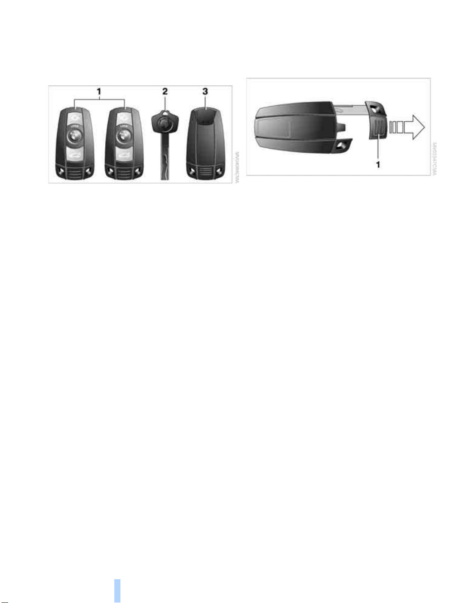
1 Remote control with integrated key
Opening and closing
2 Spare key
3 Adapter for spare key, in glove compart-
ment
Remote control with integrated key
Each remote control contains a battery which is
automatically charged in the ignition lock while
driving. Drive a longer distance with each
remote control at least twice a year to keep the
battery charged. For comfort access
remote control contains a replaceable battery,
refer to page 37.
Depending on which remote control is detected
by the vehicle during unlocking, different settings are called up and carried out in the vehicle,
refer to Personal Profile, page 29.
Information on the required maintenance is also
stored in the remote control, refer to Service
data in remote control, page 180.
*
, the
Integrated key
Press the button 1 to unlock the key.
The integrated key fits the following locks:
> Hotel function, refer to page 33
> Driver's door, refer to page 32
> Luggage compartment lid, refer to page 33.
New remote controls
To obtain additional or replace lost keys, new
remote controls with an integrated key are
available at your BMW center.
Spare key
Store the spare key in a safe place such as your
wallet. This key is not intended for regular use.
The spare key and integrated key of the remote
control fit the same locks.
Adapter for spare key
The adapter is required so that the vehicle can
be started with the spare key or radio readiness
can be switched on.
28
Page 31

Remove the adapter from the holder in the
Online Edition for Part No. 01 41 0 012 118 - © 02/06 BMW AG
glove compartment and slide the spare key into
the adapter before use.
Personal Profile
The concept
You can set a number of functions of your BMW
individually according to your preferences. Personal Profile ensures that most of these settings are stored for the remote control currently
in use without you having to do anything. When
the vehicle is unlocked, the corresponding
remote control is detected and the settings
stored for it are called up and carried out.
This means that you will always find your BMW
set to your own personal settings even if
another person with his/her own remote control
and settings has used the vehicle since the last
time you drove it. The individual settings are
stored for a maximum of four remote controls.
Personal Profile settings
Details on the settings are provided on the
specified pages.
> When unlocking with the remote control,
either unlock only the driver's door or
unlock the entire vehicle, refer to page 30
> Locking the vehicle after a short time or
after starting to drive, refer to page 33
> Assigning the programmable button on the
steering wheel, refer to page 45
> Individual settings for MDrive, refer to
page 46
> Settings for the display on the Control Dis-
play:
> Brightness of the Control Display, refer
to page 69
> Units of measure for consumption,
route/distances, temperature and pressure, refer to page 69
> Language on the Control Display, refer
to page 69
> 12h/24h clock mode, refer to page 68
> Date format, refer to page 69
> Drivelogic driving program in the Sequential
mode, refer to page 54
> Showing optical warning for PDC Park Dis-
tance Control
> Selection and brightness of the display for
the Head-Up Display
> Air distribution, temperature in the upper
body region, and intensity for the automatic
climate control, refer to page 85
> Adjusting the voice instructions for the des-
tination guidance of the navigation system
*
, refer to page 121
The most recent settings for the following are
also called up during unlocking:
> Driver's seat, exterior-mirror and steering-
wheel position, refer to page 40
> Audio sources, setting volume and tone,
refer to page 127
> The display of the stored stations for the
radio, refer to page 130
> The volume setting for the telephone, refer
to page 152
*
, refer to page 70
*
, refer to page 77
Central locking system
The concept
The central locking system is ready for operation whenever the driver's door is closed.
The system either locks or unlocks all of the following:
> Doors
Controls
29
Reference At a glanceDriving tipsCommunications NavigationEntertainmentMobility
Page 32

> Compartment in the front center console
Online Edition for Part No. 01 41 0 012 118 - © 02/06 BMW AG
> Luggage compartment lid
> Fuel filler door
Operating from outside
> via the remote control
> via the door lock
> with comfort access
These actions operate the anti-theft system at
the same time. It prevents the doors from being
unlocked using the lock buttons or door handles. The interior lamps and the courtesy lamps
are also switched on and off with the remote
control. The alarm system
the same time.
Opening and closing
You can find more detailed information on the
alarm system
on page 35.
*
via the door handles
is armed/disarmed at
Operating from inside
Via the central locking button, refer to page 32.
The fuel filler door
front center console are not locked, refer to
page 32.
In the event of a serious accident, the central
locking system unlocks automatically. The hazard warning flashers and interior lamps are also
switched on.
and the compartment in the
Opening and closing: from outside
Using remote control
Because any persons or animals left unat-
tended in a parked vehicle could lock the
doors from the inside, you should always keep
the remote control with you when you leave the
vehicle; this precaution ensures that you will
remain able to unlock the vehicle from the outside at all times.<
You can set how the vehicle is unlocked. The
setting is stored for the remote control currently
in use.
iDrive, for explanation of principle, refer to
page 16.
1. Press the button.
This opens the start menu.
2. Press the controller to open the menu.
3. Select "Vehicle settings" and press the
controller.
4. Select "Door locks" and press the control-
ler.
5. Select "Central locking" and press the con-
troller.
6. Select "Unlock button" and press the con-
troller.
7. Select a menu item:
> "All doors"
Press the button once to unlock the
entire vehicle.
> "Driver's door only"
Press the button once to unlock only
the driver's door and the fuel filler door.
Press the button twice to unlock the
entire vehicle.
*
Unlocking
Press the button.
Use it to unlock the vehicle according to current
settings.
30
8. Press the controller.
Page 33

Convenience opening mode
Online Edition for Part No. 01 41 0 012 118 - © 02/06 BMW AG
Press the button longer:
The windows are opened.
Locking doors
Press the button.
Switching on interior lamps
With vehicle locked:
Press the button.
You can also use this function to locate your
vehicle in parking garages etc.
Panic mode*
You can also trigger the alarm system in case of
danger:
Press the button for at least 3 seconds.
To switch off alarm: press any button.
Opening luggage compartment lid
Press the button for approx. 1 second.
The luggage compartment lid opens, regardless of whether it was previously locked or
unlocked.
A previously locked luggage compart-
ment lid is also locked again after closing.
During opening, the luggage compartment lid
pivots back and up. Make sure there is sufficient
clearance.<
Setting confirmation signals
You can vary or also deactivate the confirmation
signals for locking or unlocking.
1. Open the start menu.
2. Press the controller to open the menu.
3. Select "Vehicle settings" and press the
controller.
4. Select "Door locks" and press the control-
ler.
5. Select "Confirmation" and press the con-
troller.
Controls
6. Select the desired signal.
7. Press the controller.
The signal is activated.
Malfunctions
The remote control may malfunction due to
local radio waves. Should the remote control fail
to operate owing to interference of this kind,
unlock and lock the vehicle via the door lock
using a key.
If it is no longer possible to lock the vehicle
using the remote control, then the battery is
discharged. Use this remote control during an
extended drive; this will recharge the battery,
refer to page 28.
For US owners only
The transmitter and receiver units comply with
part 15 of the FCC/Federal Communication
Commission regulations. Operation is governed by the following:
FCC ID:
LX8766S
LX8766E
LX8CAS
LX8CAS2
Compliance statement:
This device complies with part 15 of the FCC
Rules. Operation is subject to the following two
conditions:
> This device may not cause harmful interfer-
ence, and
31
Reference At a glanceDriving tipsCommunications NavigationEntertainmentMobility
Page 34

> this device must accept any interference
Online Edition for Part No. 01 41 0 012 118 - © 02/06 BMW AG
received, including interference that may
cause undesired operation.
Any unauthorized modifications or
changes to these devices could void the
user's authority to operate this equipment.<
Using door lock
Opening and closing
When unlocking
1. Turning the key once unlocks the driver's
door and the fuel filler door.
2. A second turn of the key unlocks the pas-
senger door and luggage compartment lid.
Convenience operation
The windows can also be operated with the
door lock.
Turn and hold the key in the positions for
unlocking or locking.
Watch during the closing process to be
sure that no one is injured. Releasing the
key stops the operation.<
Opening and closing: from inside
This button serves to unlock or lock doors and
the luggage compartment lid, but does not activate the anti-theft system. The fuel filler door
remains unlocked.
You can also set the situations in which the
vehicle is locked.
iDrive, for explanation of principle, refer to
page 16.
1. Press the button.
This opens the start menu.
2. Press the controller to open the menu.
3. Select "Vehicle settings" and press the
controller.
4. Select "Door locks" and press the control-
ler.
5. Select "Central locking" and press the con-
troller.
Manual operation
In the event of an electrical malfunction, you can
turn a key all the way to the right or left in the
door lock to lock or unlock the driver's door.
32
6. Select a menu item:
> "Relock door if not opened"
The central locking system automatically locks the vehicle after a short time
when no door has been opened.
Page 35

> "Lock after driving"
Online Edition for Part No. 01 41 0 012 118 - © 02/06 BMW AG
The central locking system automatically locks the vehicle as soon as you
start to drive.
7. Press the controller.
The setting is selected.
The setting is stored for the remote control currently in use.
Unlocking and opening doors
> Either unlock both doors at the same time
with the button for the central locking system and then pull the door handle above the
armrest or
> pull the door handle for each door twice: the
first pull unlocks the door, and the second
one opens it.
Locking doors
> Use the central locking button to lock both
of the doors simultaneously, or
> Press down the lock button of a door.
To prevent you from being locked out, the
open driver's door cannot be locked using
the lock button.
Because any persons or animals left unat-
tended in a parked vehicle could lock the
doors from the inside, you should always keep
the remote control with you when you leave the
vehicle; this precaution ensures that you will
remain able to unlock the vehicle from the outside at all times.<
Hotel function
The hotel function locks the compartment in
the front center console and the luggage compartment lid separately and disconnects them
from the central locking system. If you hand
over the remote control without the integrated
key, refer to page 28, e.g. at a hotel, then this
prevents access to the luggage compartment
and to the compartment in the front center console.
Turn the key to the right, refer to illustration,
until the key slot points in the direction of travel
and then remove:
The hotel function is activated after subsequent
locking or unlocking of the vehicle. The system
locks the luggage compartment lid and the
compartment in the front center console and
disconnects them from the central locking system.
Manual release
In order to manually unlock the compartment in
the front center console in the event of an electrical malfunction, turn the key all the way to the
right until it reaches the stop.
If unlocking was manual, return the lock to
the home position, i.e. all the way back to
the left, before reactivating the hotel function.<
Doors
Automatic soft closing*
To close the doors, merely press it closed gently. The closing process will then be carried out
automatically.
Make sure that the closing path of the
doors is clear; as otherwise injuries may
result.<
Luggage compartment lid
During opening, the luggage compartment lid pivots back and up. Make sure
there is sufficient clearance.<
Controls
33
Reference At a glanceDriving tipsCommunications NavigationEntertainmentMobility
Page 36

Opening from inside
Online Edition for Part No. 01 41 0 012 118 - © 02/06 BMW AG
Press the button:
The luggage compartment lid opens, provided
that it is not locked or the hotel function is not
activated, refer to the above section.
Opening and closing
Opening from outside
If you use the lock to open the luggage
compartment lid while the alarm system
is armed, the alarm will be triggered. To prevent
this, you should deactivate the alarm beforehand.
If the alarm has been triggered accidentally,
switch off the alarm, refer to page 35.<
Closing
Make sure that the closing path of the
luggage compartment lid is clear; otherwise, injuries may result.<
The handle recesses on the interior trim of the
luggage compartment lid make it easier to pull
down.
Press the upper half of the BMW emblem or
press the button on the remote control for
approx. 1 second: the luggage compartment lid
opens.
Manual release
The luggage compartment lid lock is located
under the BMW emblem. All keys, refer to
page 28, fit the luggage-compartment lid lock.
Turn the key toward the right up to the stop: the
luggage compartment lid opens.
34
Emergency release
Pull lever in luggage compartment. The luggage compartment lid is unlocked.
Luggage compartment
There are four lashing eyes on the inner corners
of the luggage compartment for securing lug-
*
gage nets
position.
Also refer to Securing cargo, page 101.
or securing straps to fix luggage in
Page 37

Alarm system
Online Edition for Part No. 01 41 0 012 118 - © 02/06 BMW AG
The concept
The vehicle alarm system responds:
> To the opening of a door, the hood, or the
luggage compartment lid
> To movements in the vehicle interior: inte-
rior motion sensor, refer to page 35
> To changes in the vehicle's tilt if someone
attempts to steal the wheels or tow the
vehicle
> To interruptions in battery voltage
Unauthorized operations are briefly signaled by
the alarm system:
> by triggering an acoustic alarm
> by switching on
> by flashing the high beams
Arming and disarming alarm system
When you lock or unlock the vehicle, either with
the remote control or at the door lock, the alarm
system is armed or disarmed at the same time.
You can open the luggage compartment lid,
even with the system armed, by using the
button of the remote control, refer to page 31.
When the luggage compartment lid is closed,
it is once again locked and monitored.
Switching off alarm
> Unlock the vehicle using the remote control,
refer to page 30, or
> insert the remote control all the way into the
ignition lock.
the hazard warning flashers
Indicator lamp displays
> The indicator lamp below the interior rear-
view mirror flashes continuously: the system is armed.
> The indicator lamp flashes after locking: the
doors, hood or luggage compartment lid are
not properly closed. Even if you do not close
the alerted area, the system begins to monitor the remaining areas, and the indicator
lamp flashes continuously after approx.
10 seconds. However, the interior motion
sensor is not activated.
> After the vehicle is unlocked, the indicator
lamp goes out: no manipulation or
attempted intrusions have been detected in
the period since the system was armed.
> The indicator lamp flashes after unlocking
until the remote control is inserted into the
ignition lock, however for a maximum of
approx. 5 minutes: an attempted entry has
been detected in the period since the system was armed.
Tilt alarm sensor
Monitors the inclination of the vehicle. The
alarm system reacts, for example, if someone
attempts to steal the wheels or tow the vehicle.
Controls
Interior motion sensor
The condition for proper operation of the interior motion sensor is closed windows.
Avoiding unintentional alarms
The tilt alarm sensor and interior motion sensor
may be switched off at the same time.
This prevents unintentional alarms, e.g. in the
following situations:
35
Reference At a glanceDriving tipsCommunications NavigationEntertainmentMobility
Page 38

> In stacking garages
Online Edition for Part No. 01 41 0 012 118 - © 02/06 BMW AG
> When transporting on car-carrying trains
> When animals are to remain in the vehicle
Switching off tilt alarm sensor and
interior motion sensor
Press the button on the remote control
again as soon as the vehicle is locked.
The indicator lamp lights up briefly and then
flashes continuously. The tilt alarm sensor and
the interior motion sensor are switched off until
the vehicle is unlocked and locked again.
Comfort access*
Opening and closing
Comfort access enables you to access your
vehicle without having to hold the remote control in your hand. It is sufficient to carry the
remote control with you, e.g. in your jacket
pocket. The vehicle automatically detects the
related remote control in the immediate vicinity
or in the interior.
Comfort access supports the following functions:
> Unlocking/locking vehicle
> Comfort locking
> Opening luggage compartment lid
separately
> Starting engine
Functional requirement
> The vehicle or the luggage compartment lid
can only be locked if the vehicle detects that
the remote control you are carrying is outside the vehicle.
> The next unlocking and locking cycle is not
possible until after approx. 2 seconds.
> The engine can only be started if the vehicle
detects that the remote control is located in
the vehicle.
Comparison with ordinary remote
control
You can control the functions mentioned previously with the comfort access or by pressing
the buttons on the remote control. Before doing
so, please familiarize yourself with the information on opening and closing, starting on
page 28.
The special features when using comfort
access are described below.
Should as short delay occur when open-
ing or closing the windows, the system is
checking whether a remote control is located in
the vehicle. Please repeat opening or closing if
necessary.<
Unlocking
Completely grasp a door handle, arrow 1.
This corresponds to pressing the button.
If a remote control is detected in the interior
after unlocking, the electric steering-wheel lock
disengages, refer to page 50.
Locking doors
> For the driver's door, touch the area high-
lighted in the picture, arrow 2, with your finger for approx. 1 second.
> For the passenger's door, touch the area
highlighted in the picture, arrow 3, with your
finger for approx. 1 second.
This corresponds to pressing the button.
Please make sure that the ignition and all
current consumers are switched off
before locking to save the battery.<
36
Page 39

Comfort locking
Online Edition for Part No. 01 41 0 012 118 - © 02/06 BMW AG
Hold a finger or the back of the hand on the surface, arrow 2 or 3.
The windows are closed.
Watch during the closing process to be
sure that no one is injured. Removing the
hand from the door handle stops the closing
process immediately.<
Replacing battery
The remote control for comfort access contains
a battery which must be replaced occasionally.
1. Remove integrated key from remote con-
trol, refer to page 28.
Opening luggage compartment lid
separately
Press the upper half of the BMW emblem.
This corresponds to pressing the button.
If a remote control accidentally left in the
luggage compartment is detected inside
the locked vehicle after the luggage compartment lid has been closed, then the luggage
compartment lid opens again. The hazard warn-
*
ing flashers flash and a signal
sounds.<
Switching on radio readiness
By briefly pressing the Start/Stop button, you
switch on the radio readiness, refer to page 50.
When doing so, do not depress the brake
pedal, otherwise the engine will start.<
Starting engine
You can start the engine or switch on the ignition if a remote control is located on the interior
of the vehicle. It need not be inserted in the ignition lock, refer to page 50.
If you take the remote control with you when
leaving the vehicle with the engine running, a
warning lamp lights up. In addition, a message
appears on the Control Display. As long as no
remote control is detected in the vehicle, it is
only possible to restart the engine within
approx. 10 seconds after it is switched off.
Controls
2. Remove cover.
3. Insert new battery with positive side facing
upward.
4. Press cover closed.
Return used battery to a recycling collection point or to your BMW center.<
Windows
To prevent injuries, exercise care when
closing the windows and keep them in
your field of vision until they are shut.
Always take along the remote control when you
leave the vehicle; otherwise, children could, for
example, operate the windows and injure themselves.<
Opening, closing
Malfunction
The comfort access function may malfunction
due to local radio waves. If this occurs, then
open or close the vehicle with the buttons on
the remote control or with a key. To start the
engine after this, insert the remote control in the
ignition lock.
> Press switch to resistance point:
The window continues to open for as long
as you hold down the switch.
37
Reference At a glanceDriving tipsCommunications NavigationEntertainmentMobility
Page 40

> Press the switch beyond the resistance
Online Edition for Part No. 01 41 0 012 118 - © 02/06 BMW AG
point:
The window opens automatically. Pressing
the switch again stops the opening movement.
You can close the windows in the same manner
by pulling the switch.
For information on using the convenience operation mode at the door lock or with the remote
control, refer to page 31 or 32.
For information on comfort closing with comfort
access, refer to page 37.
After switching off ignition
You can still operate the windows with the
Opening and closing
remote control removed or the ignition
switched off for approx. 1 minute, as long as
neither of the doors has been opened.
Pinch protection system
If the closing force rises beyond a predefined
threshold during closing, the system will immediately stop moving the window prior to lowering it slightly.
Despite the pinch protection system,
inspect the window's travel path prior to
closing it, as the safety system might fail to
detect certain kinds of obstructions, such as
thin objects, and the window would continue
closing.
Pulling the switch beyond the resistance point
and holding it limits the response of the pinch
protection system. In this case, the window will
respond to forces beyond a defined threshold
by opening only slightly.
If you pull the switch past the resistance point
again within approx. 4 seconds and hold i t there,
the pinch protection system will be deactivated.
Do not install any accessories in the range of
movement of the windows, as otherwise the
pinch protection system will be impaired.<
38
Page 41

Adjustments
Online Edition for Part No. 01 41 0 012 118 - © 02/06 BMW AG
Sitting safely
The ideal sitting position can make a vital contribution to relaxed, fatigue-free driving. In the
interaction with the safety belts, the head
restraints and the airbags, the seat position
plays an important role in an accident. To
ensure that the safety systems operate with
optimal efficiency, we strongly urge you to follow the instructions contained in the following
section.
For additional information on transporting children safely, refer to page 48.
Airbags
Always maintain an adequate distance
between yourself and the airbags. Always
hold the steering wheel by its rim with hands at
the 9 o'clock and 3 o'clock positions to minimize the risk of injuries to your hands and arms
in the event of airbag deployment.
No one and nothing is to come between the airbags and the seat occupant.
Do not use the cover of the front airbag on the
front passenger side as a storage area. Make
sure that the front passenger is sitting correctly
and does not rest feet or legs on the instrument
panel, otherwise leg injuries can occur if the
knee and front airbags are triggered.
Make sure that occupants do not rest their head
on the side or head airbag; otherwise, injuries
can occur if the airbags are triggered.<
Even if you adhere to all the instructions, injuries resulting from contact with airbags cannot
be fully excluded, depending on the circumstances. The ignition and inflation noise may
provoke a mild hearing loss in extremely sensitive individuals. This effect is usually only temporary.
For airbag locations and additional information
on airbags, refer to page 75.
Head restraints
A correctly adjusted head restraint reduces the
risk of injury to cervical vertebrae in an accident.
Adjust the head restraint so that its center
is approx. at ear level. Otherwise there is
increased danger of injury in the event of an
accident.<
Head restraints, refer to page 41.
Safety belt
Before every drive, make sure that safety belts
are being worn at all of the occupied seats. Airbags complement the safety belt as an additional safety device, but they do not represent a
substitute.
Your vehicle has four seats that are each
equipped with a safety belt.
Never allow more than one person to
wear a single safety belt. Never allow
infants or small children to ride in a passenger's
lap. Make sure that the belt lies low around the
hips in the lap area and does not press on the
abdomen. The safety belt may not lie across the
neck, rub on sharp edges, be routed over solid
or breakable objects or be pinched. Wear the
safety belt without twisting, snugly across the
lap and shoulders, as close to the body as possible. Otherwise, the belt can slip over the hips
in the lap area in a frontal impact and injure the
abdomen. Avoid wearing clothing that prevents
the belt from fitting properly and pull the shoulder belt upward periodically to readjust the tension across your lap in order to avoid a reduction in the retention effect of the safety belt.<
Safety belts refer to page 42.
Seats
Note before adjusting
Never attempt to adjust your seat while
operating the vehicle. The seat could
respond with unexpected movement and the
Controls
39
Reference At a glanceDriving tipsCommunications NavigationEntertainmentMobility
Page 42

ensuing loss of vehicle control could lead to an
Online Edition for Part No. 01 41 0 012 118 - © 02/06 BMW AG
accident.
On the front passenger side as well, do not tilt
the backrest too far toward the rear. Failure to
observe this precaution can prevent the belt
from providing effective protection against
injury, as the passenger could slide under the
belt in an accident.<
Also follow the instructions regarding damage
to the safety belt on page 43.
Adjustments
Seat adjustment
To ensure that the safety systems continue to provide optimized protection,
please follow the adjustment instructions on
page 39.<
1 Inclination
2 Longitudinal direction
3 Height
4 Backrest
The upper hips and spinal column receive supplementary support to help you maintain a
relaxed, upright sitting position.
> Increase or decrease curvature:
Press front or rear of switch.
> Move curvature up or down:
Press top or bottom of switch.
Thigh support
You can also adjust the thigh support manually:
pull the lever and adjust the thigh support in the
longitudinal direction.
Seat, mirror and steering wheel memory
5 Backrest width
6 Lumbar support
Adjusting lumbar support
You can also adjust the contours of the backrest
to obtain additional support in the lumbar
region.
40
You can store and select three different adjustment settings for the driver's seat, exterior mirrors and steering wheel.
The adjustments of the thigh support and the
backrest width are not stored in the memory.
Storing
1. Switch on radio readiness or ignition, refer
to page 50.
2. Adjust the desired seat, exterior mirror and
steering-wheel positions.
Page 43

3. Press the button:
Online Edition for Part No. 01 41 0 012 118 - © 02/06 BMW AG
The LED in the button lights up.
4. Press the desired memory button 1, 2 or 3:
The LED goes out.
Requesting
Do not request a position from the memory while the vehicle is moving. There is a
risk of accident from unexpected movement of
the seat or steering wheel.<
Convenience mode
1. Open the driver's door after unlocking or
switch on radio readiness, refer to page 50.
2. Briefly press the desired memory button 1,
2 or 3.
The system immediately cancels the adjustment procedure when you briefly press one of
the seat adjustment switches or one of the
memory buttons.
The adjusting procedure for the steering wheel
is immediately interrupted if you briefly press
the switch for the steering wheel adjustment in
any direction, refer to page 44.
1. Open the start menu.
2. Press the controller to open the menu.
3. Select "Vehicle settings" and press the
controller.
4. Select "Door locks" and press the control-
ler.
Controls
5. Select "Central locking" and press the con-
troller.
6. Select "Last seat pos." and press the con-
troller.
7. Select "After unlocking" or "After door
opened".
Safety feature
1. Close the driver's door and switch ignition
on or off, refer to page 50.
2. Press the desired memory button 1, 2 or 3
and maintain pressure until the adjustment
process has been completed.
If the button was pressed inadvertently:
press the button again; the LED goes out.
Activating with remote control
The last positions of the driver's seat, external
rearview mirrors, and steering wheel are stored
for the remote key currently in use.
You can choose when the position is requested:
> Request when unlocking vehicle
> Request when opening driver's door
iDrive, for explanation of principle, refer to
page 16.
8. Press the controller.
To cancel the request:
Select "Deactivated" and press the controller.
When using this feature, always make
sure that the footwell behind the driver's
seat is empty and unobstructed. If you fail to do
so, any persons or objects behind the seat
could be injured or damaged by a rearward
movement of the seat.<
Front head restraints
A correctly adjusted head restraint reduces the
risk of injury to cervical vertebrae in an accident.
41
Reference At a glanceDriving tipsCommunications NavigationEntertainmentMobility
Page 44

Adjust the head restraint so that its center
Online Edition for Part No. 01 41 0 012 118 - © 02/06 BMW AG
is approx. at ear level. Otherwise there is
increased danger of injury in the event of an
accident.<
Adjusting height
Adjustments
> To raise: pull the head restraint upward.
> To lower: slide the head restraint down-
ward.
To reach the lowest position, press the
button, refer to arrow 1.<
Adjusting tilt angle
Swivel the head restraints.
Removal
1. Pull the head restraint upward to the stop.
2. Press the button, arrow 1, and remove the
head restraint.
Only remove head restraint when no pas-
senger is seated in the respective seat, as
otherwise you will be in violation of the law.
Reinstall head restraint before passengers use
the respective seat.<
Releasing backrest
Pull the lever upward and fold the backrest forward.
The lever is designed so that the safety belt can
be hooked onto it. This enables you to fasten
the safety belt more conveniently.
Safety belts
To ensure that the safety systems continue to provide optimized protection,
please follow the adjustment instructions on
page 39.<
Before every drive, make sure that safety belts
are being worn at all of the occupied seats. Airbags complement the safety belt as an additional safety device, but they do not represent a
substitute.
Installation
Insert head restraint into the sockets and
adjust.
Getting in back
Before starting to drive, fold backrests
back, otherwise there is the danger of
accident due to an unexpected movement of
the seat.<
42
Page 45

Fastening
Online Edition for Part No. 01 41 0 012 118 - © 02/06 BMW AG
Make sure you hear the latch plate engage in
the belt buckle.
Releasing
1. Hold the belt firmly.
2. Press the red button in the belt buckle.
3. Guide the belt into its reel.
The shoulder strap's anchorage point will be in
the correct position for adults of every build if
the seat is correctly adjusted, refer to page 39.
Safety belt reminder for driver's seat
and passenger seat*
The indicator lamp lights up and a signal sounds. At the same time, an addi-
tional message appears on the Control
Display. Please check whether safety belts are
being worn correctly.
The safety belt memory is operative at speeds
above approx. 5 mph/8 km/h. It can also be activated if objects are placed on the passenger
seat.
Damage to safety belts
In the event of loads caused by accidents
or other damage: replace the belt system
including the safety belt tensioner and any child
restraint systems, and have the belt anchor
points checked. Have this work carried out only
by a BMW center or a workshop that works
according to BMW repair procedures with
appropriately trained personnel. Otherwise correct operation of this safety equipment is not
guaranteed.<
Heated seats
Controls
The temperature setting advances one step in
its control sequence each time you press the
button. The maximum temperature is supplied
when three LEDs are lit.
To switch off:
Press the button longer.
Mirrors
Exterior mirrors
The mirror on the passenger's side is
more curved than the driver's mirror.
Objects reflected in the mirror are closer than
they appear. Do not estimate the distance of
following traffic based on what you see in the
mirrors; otherwise, there is an increased accident risk.<
1 Adjustments
2 Switching to the other mirror or to the
automatic parking function
3 Folding mirrors in and out
Storing the mirror positions, refer to Seat, mirror and steering wheel memory on page 40.
*
43
Reference At a glanceDriving tipsCommunications NavigationEntertainmentMobility
Page 46

Adjusting manually
Online Edition for Part No. 01 41 0 012 118 - © 02/06 BMW AG
You can also adjust the mirrors manually by
pressing against the outer edges of their mirror
glass.
Folding exterior mirrors in and out
Pressing button 3 allows you to fold mirrors
in and out up to a speed of approx. 20 mph/
30 km/h. This is advantageous, for example, in
car washes, narrow streets or for bringing mir-
Adjustments
r or s t ha t h a ve be en ma nu a ll y f ol de d- in b ac k i nt o
the correct position. Folded-in mirrors automatically fold down at a speed of approx. 25 mph/
40 km/h.
Tilting down passenger-side mirror –
automatic parking function
Activating
1. Slide switch into the driver's side mirror
position, arrow 1.
Automatic functions
> Below a certain outdoor temperature, both
exterior mirrors are automatically heated
when the motor is running or the ignition is
switched on.
> When the vehicle is moving forward, the
interior and exterior mirrors dim as a function of the incoming light.
The interior mirror is provided with two photocells to control its automatic dimming function.
One is integrated into the mirror glass, refer to
arrow, while the other is located at a position
slightly offset from this on the back of the mirror
housing.
For trouble-free operation, keep the photocells
clean and do not cover the area between the
interior rearview mirror and the windshield. Also
do not attach stickers to the windshield in front
of the mirror.
2. Engage reverse gear or selector lever posi-
tion R.
The mirror glass tilts downward somewhat
on the passenger's side. This allows the
driver to see the area immediately adjacent
to the vehicle – such as a curb – when parking, etc.
Deactivating
Slide switch into the passenger side mirror
position, arrow 2.
Steering wheel
Adjustments
Do not adjust the steering wheel while the
vehicle is moving. There is a risk of acci-
dent as the result of unexpected movement.<
44
The steering wheel can be adjusted in four
directions.
Page 47

Storing the steering-wheel position, refer to
Online Edition for Part No. 01 41 0 012 118 - © 02/06 BMW AG
Seat, mirror and steering wheel memory,
page 40.
Electric steering wheel lock
The steering wheel locks or unlocks automatically when the remote control is removed or
inserted, refer to page 50.
Easy entry/exit
To make it easier to enter and exit the vehicle,
the steering wheel temporarily moves into the
uppermost position.
Programmable button on steering
wheel
You can program the button individually.
The setting is stored for the remote control currently in use.
iDrive, for explanation of principle, refer to
page 16.
1. Press the button.
This opens the start menu.
2. Press the controller to open the menu.
3. Select "Vehicle settings" and press the
controller.
4. Change to upper field if necessary. Turn the
controller until "Steering wheel button" is
selected and press the controller.
A list of different functions appears:
> "Navigation voice instructions"
Voice instructions of the navigation system
*
> "Air recirculation on / off"
Permanently shutting off outside air,
refer to AUC Automatic recirculated air
control on page 87
> "Mute on / off"
Mutes the audio sources
> "Monitor on / off"
Switches the Control Display on/off
> "Telephone list"
Display/hide phone book or last list of
stored phone numbers displayed
> "Next entertainment source"
Changes audio source
5. Select the desired function unit and press
the controller.
*
Operating function
Press the button on the steering wheel.
If you have programmed "Navigation voice
instructions" for the button:
> To switch voice instructions on/off:
Maintain pressure on the button for several
seconds.
> To repeat the last voice instruction:
Press the button.
Controls
45
Reference At a glanceDriving tipsCommunications NavigationEntertainmentMobility
Page 48

MDrive
Online Edition for Part No. 01 41 0 012 118 - © 02/06 BMW AG
With MDrive you can configure several individual settings for your vehicle on the Control Display and activate them simultaneously with the
button on the steering wheel.
Configuring settings
With the ignition switched on you can change
the settings of MDrive on the Control Display.
Adjustments
iDrive, for explanation of principle, refer to
page 16.
1. Press the button.
This opens the start menu.
2. Press the controller to open the menu.
3. Select "Vehicle settings" and press the
controller.
4. Move the controller forward if necessary so
that the marking is located in the upper
field. Turn the controller until "MDrive" is
selected and press the controller.
> "EDC"
Programs of the Electronic Damping
Control, refer to page 73
> "DSC"
Dynamic Stability Control and
M Dynamic Mode, refer to page 71
> "POWER"
Programs of the M Engine Dynamic
Control, refer to page 55
> "Head-Up Display"
Views of the Head-Up Display, refer to
page 77
You can reset all settings for MDrive to their
default values:
> "Reset to default"
5. Select the desired function.
6. Press the controller.
7. Turn the controller to select the desired set-
ting.
*
The functions contained in MDrive are displayed:
> "SMG Drivelogic"
Sequential Manual Transmission with
Drivelogic: shifting modes and Drivelogic driving programs, refer to page 54
46
"Unchanged" retains the current setting
made outside of MDrive.
8. Press the controller.
The setting is stored for the remote control currently in use.
Page 49

Activating settings
Online Edition for Part No. 01 41 0 012 118 - © 02/06 BMW AG
Press the button on the steering wheel.
The indicator lamp in the instrument
cluster lights up. The settings made on
the Control Display for the functions
contained in MDrive are active.
Pressing the button again deactivates MDrive.
If the indicator lamp flashes after pressing
the button, MDrive was unable to react, as
the ABS Antilock Brake System or DSC
Dynamic Stability Control is currently controlling the vehicle stability. Press the button
again when the indicator lamp no longer
flashes.<
Even with MDrive activated, you can change
individual settings outside MDrive, e.g. with the
buttons in the center console. To reactivate all
settings made for MDrive on the Control Display: press the button twice.
Controls
47
Reference At a glanceDriving tipsCommunications NavigationEntertainmentMobility
Page 50

Transporting children safely
Online Edition for Part No. 01 41 0 012 118 - © 02/06 BMW AG
The right place for children
Do not leave children unattended in the
vehicle; otherwise, they could endanger
themselves and other persons, e.g. by opening
the doors.<
Children always in the rear
Accident research shows that the safest place
for children is in the back.
Children younger than 13 years of age or
with a height under 5 ft/150 cm may only
be transported in the rear in child restraint systems which correspond to the age, weight and
height of the child. Otherwise there is an
increased danger of injury in an accident.<
Children 13 years of age or older must wear a
safety belt as soon as a suitable child restraint
Transporting children safely
system can no longer be used due to their age,
size and weight.
With the exception of the driver's seat, all seats
in your BMW comply with the recommendations of the standard SAE J1819 for the safe
securing of child restraint systems in motor
vehicles.
Installing child restraint systems
Follow child-restraint system manufac-
turer's instructions for the selection,
installation and use of child restraint systems.
Otherwise the degree of protection they offer
may be reduced.<
Backrest width on front passenger seat
Before mounting a child restraint system
on the front passenger seat, the backrest
width adjustment must be open completely.<
1. Adjust the backrest width to the fully open
position, refer to page 40.
2. Install child's seat.
Child seat security
Exception for front passenger seat
Should it be necessary to use a child
restraint system on the front passenger
seat, the front, knee and side airbag on the passenger side must be deactivated. Otherwise,
there is an increased risk of injury for the child if
the airbags are triggered, even with a child
restraint system. Your BMW center will be glad
to advise you.<
For more information on automatic deactivation
of the front passenger airbags, refer to page 76.
48
All rear safety belts and the safety belt for the
front passenger can be locked against pulling
out to secure child restraint systems.
Locking safety belt
1. Secure the child restraint system with the
belt.
2. Pull out the belt webbing completely.
3. Allow the belt webbing to be pulled in and
pull taut against the child restraint system.
The safety belt is locked.
Page 51

Unlocking safety belt
Online Edition for Part No. 01 41 0 012 118 - © 02/06 BMW AG
1. Open the belt buckle.
2. Remove the child restraint system.
3. Allow the belt webbing to be pulled in com-
pletely.
Child restraint system with tether strap
Rear seats
There are two additional mounting points for
child restraint systems with a tether strap, refer
to arrows.
Placement of tether strap
1. Fold anchor fitting into upright position.
2. Push head restraint downward.
3. Guide tether strap over head restraint and
hook onto anchor fitting.
The mountings for the LATCH child-restraint
fixing system are located under the points
marked with the symbols. They are not visible
from the outside.
Before attaching the LATCH child's seat, pull
the belt away from the region of the childrestraint fixing system.
Controls
LATCH child-restraint fixing system
LATCH: Lower Anchor and Tethers for CHildren.
To attach a LATCH child's seat, follow the
operating and safety instructions of the
child's seat manufacturer.<
49
Reference At a glanceDriving tipsCommunications NavigationEntertainmentMobility
Page 52

Driving
Online Edition for Part No. 01 41 0 012 118 - © 02/06 BMW AG
Ignition lock
Driving
Insert the remote control as far as possible into
the ignition lock.
> Radio readiness switches on.
Some electrical devices are ready for operation.
> The electric steering-wheel lock audibly
disengages.
Before moving the vehicle, insert the
remote control into the ignition lock;
otherwise, the electric steering-wheel lock will
not be unlocked and the vehicle cannot be
steered.<
Removing remote control from ignition
lock
Briefly press in the remote control; it pops out
slightly.
> The ignition is switched off if it was still
switched on.
> The electric steering-wheel lock audibly
engages.
Start/Stop button
Briefly pressing the Start/Stop button several
times switches the radio readiness or the ignition on and off.
Briefly pressing the Start/Stop button
with the brake pedal depressed and the
selector lever in position N starts the engine.<
Radio readiness
Some electrical devices are ready for operation.
The last information of the onboard computer
selected is displayed in the instrument cluster.
Radio readiness is automatically switched off:
> when the remote control is removed from
the ignition lock
> with comfort access
sitive surface on the door handle, refer to
Locking doors on page 36
Ignition on
All current consumers are ready for operation.
The odometer and the trip odometer are displayed in the instrument cluster, refer to
page 59.
Please switch off the ignition and the current consumers which are not required
when the engine is not running to save the battery.<
*
by touching the sen-
50
Radio readiness and ignition off
All indicator and warning lamps in the instrument cluster go out.
Page 53

Starting engine
Online Edition for Part No. 01 41 0 012 118 - © 02/06 BMW AG
Do not run the engine in closed rooms,
otherwise the inhaling of toxic exhaust
gases can cause unconsciousness and death.
The exhaust gases contain carbon monoxide,
an odorless and colorless, but highly toxic gas.
Never leave an unattended vehicle with the
engine running, as such a vehicle represents a
potential safety hazard.
Before leaving the vehicle with the engine running, move the selector lever into the N position
and set the handbrake, otherwise the vehicle
can begin to roll.<
When starting the engine, do not press the
accelerator pedal.
Do not allow the engine to warm up by leaving it
running while the vehicle remains stationary.
Instead, begin to drive immediately at a moderate engine speed.
Do not press the brake pedal as long as
you do not want to start the engine. The
engine starts immediately when you briefly
press the Start/Stop button with the brake
pedal depressed.<
1. Depress brake pedal.
2. Place selector lever in position N.
3. Briefly press Start/Stop button.
The system responds by automatically engaging the starter for a certain period and automatically disengaging it as soon as the engine
starts.
If the engine does not start, shift back to
the last selector lever position selected,
refer to the instrument cluster display or the
selector lever. Then select the position N.
You cannot start off with the hood open.
When the engine is cold, the exhaust system
has a slightly metallic undertone due to the system design.<
Avoid frequent starting in quick succes-
sion or repeated starting attempts in
which the engine does not start. Otherwise, the
fuel is not burned at all or is burned inadequately and there is a danger of overheating and
damage to the catalytic converter.<
Special starting conditions
Depress the accelerator pedal halfway when
starting the engine in the following situations:
> The engine fails to start on the first attempt,
e.g. if it is very hot or cold.
> The engine is started at very low tempera-
tures, below approx. +5 7/– 15 6, at high
altitudes, over approx. 3,300 ft/1,000 m.
Switching engine off
Do not remove the remote control from
the ignition lock while the vehicle is rolling, otherwise the steering wheel lock would
engage while steering.
When leaving the vehicle, always take the
remote control with you.
When parking on a downhill incline, apply the
handbrake, as otherwise the vehicle could roll
away.<
1. Apply handbrake.
2. Move selector lever into a drive position.
3. Briefly press Start/Stop button.
A signal sounds when the position N is
engaged and the handbrake is not set when
switching off the engine.
Handbrake
The handbrake is primarily intended to prevent
the vehicle from rolling while parked; it brakes
the rear wheels.
Controls
51
Reference At a glanceDriving tipsCommunications NavigationEntertainmentMobility
Page 54

Indicator lamp
Online Edition for Part No. 01 41 0 012 118 - © 02/06 BMW AG
The indicator lamp lights up, and a signal also sounds when starting off. The
handbrake is engaged.
Driving
Indicator lamp for Canadian models.
Engaging
The lever engages automatically.
Releasing
Pull slightly upwards, press the button and
lower the lever.
If exceptional circumstances should
make it necessary to engage the handbrake while the vehicle is in motion, do not pull
it too strongly. In doing so, continuously press
the button of the handbrake lever. Otherwise,
excessive pressure can lead to the rear wheels
locking up and loss of traction – fishtailing – at
the rear axle.<
To prevent corrosion and one-sided brak-
ing action, occasionally apply the handbrake lightly when the vehicle is slowly coming
to a stop if the traffic conditions are suitable.
The brake lamps do not light up when the handbrake is engaged.<
Sequential Manual Transmission with Drivelogic
The concept
The SMG Sequential Manual Transmission
with Drivelogic is an automated manual trans-
mission in which an electrohydraulic system
handles the clutching and gear changes.
The Sequential Manual Transmission is operated with the selector lever and two shift paddles on the steering wheel.
It offers the following functions:
> Choice of manual or automatic mode:
Sequential mode or Drive mode
> Selection option between different driving
programs, Drivelogic, refer to page 54
> Upshift display, shift lights, refer to page 55
> Automatic downshifting and prevention of
incorrect shifting even in sequential operation
> Automatic double clutching
Selector lever positions
> R: Reverse gear
> N: Neutral, idle
> Β: Drive position:
> +: manual upshifting
> –: manual downshifting
> D/S: switch between Drive mode and
Sequential mode
Shiftlock
Press the brake pedal before shifting out of N;
the shift command will not be executed unless
the brake is applied.
R Reverse
Select only when the vehicle is stationary.
52
Page 55

N Idle
Online Edition for Part No. 01 41 0 012 118 - © 02/06 BMW AG
Always engage before starting engine.
If the driving situation requires, e.g. when downshifting on a slippery road surface, the Sequential Manual Transmission automatically
clutches and then declutches again, i.e. it is not
necessary to engage idling manually.
N is automatically engaged after just a
few seconds when you open the driver's
door or the hood with the engine running and do
not operate either pedals, shift paddles or the
selector lever. In these cases, to start off after
closing the driver's door or the hood, first move
the selector lever into the position N and then
into the drive position.<
S Sequential mode
You can shift up and down using the shifting
paddles or the selector-lever. You do not need
to remove your foot from the accelerator to do
so.
After every engine start, as soon as the selector
lever is pushed to the right into the drive position Β and the brake pedal is pressed, the
Sequential mode is activated.
Starting off is also possible on a level road surface in second gear, e.g. in case of ice.
In the following situations, the Sequential Manual Transmission thinks for you:
> Upshifts and downshifts are executed only
when they will result in a plausible combination of engine and vehicle speed; thus, for
example, the system will not execute a
downshift that would cause the engine to
overrev.
> When the vehicle is stationary, the trans-
mission automatically downshifts into first
gear.
> Shortly before dropping below a gear-
dependent minimum speed, the transmission downshifts automatically even without
your intervention.
D Drive mode
In the Drive mode, all forward gears are shifted
automatically.
Shifting from Sequential mode to Drive mode:
press selector lever to the right toward D/S.
To switch back into the Sequential mode: press
selector lever to the right again toward D/S or
shift using the shift paddles or the selector
lever.
Kick-down: for rapid acceleration, e.g. passing,
press the accelerator pedal as far down as it will
go. You achieve maximum acceleration.
Displays in instrument cluster
1 Gear 1 to 7, R, N engaged
2 Selected driving program,
matches the number of illuminated fields,
refer to Drivelogic on page 54
3 The currently engaged gear is displayed,
followed by a D in the Drive mode.
A flashing gear display indicates to you
that the driver's door is open with the
engine running.
N is automatically engaged after just a few seconds when you open the driver's door or the
hood with the engine running and the vehicle
stopped, and do not operate either pedals, shift
paddles or the selector lever.<
Gear changes
Using selector-lever
> To upshift, pull the selector-lever back.
> To downshift, push the selector-lever for-
ward.
Controls
53
Reference At a glanceDriving tipsCommunications NavigationEntertainmentMobility
Page 56

Using shift paddles on steering wheel
Online Edition for Part No. 01 41 0 012 118 - © 02/06 BMW AG
Driving
> To upshift, briefly pull the right shift
paddle +.
> To downshift, briefly pull the left shift
paddle –.
Selecting driving program with button
in center console
Press the button repeatedly until the desired
driving program is displayed in the instrument
cluster, refer to page 53.
Drivelogic
With Drivelogic various driving programs are
available to you.
Each time you change between the Sequential
mode and the Drive mode, the driving program
last selected in the respective mode is active.
Exception: after the first change from the
Sequential to the Drive mode, driving program 3
is active.
In Drive mode
Five driving programs, from relaxed 1 to sporty/
highly dynamic 5 are available for selection.
In Sequential mode
You can choose from six driving program from
balanced/dynamic 1 to sporty/purist 6.
Each time the engine is started, driving program 3 is activated.
The sporty/purist driving program 6 is only
available with the DSC Dynamic Stability Control deactivated, refer to page 71. When DSC
is activated, the system switches from driving
program 6 to 5.
To maintain vehicle stability, always drive
with the DSC switched on when possi-
ble.<
Selecting driving program via button
on steering wheel
You can also activate your preferred driving program with the button on the steering wheel,
refer to MDrive on page 46.
With the ignition switched on you can change
the settings of MDrive on the Control Display.
iDrive, for explanation of principle, refer to
page 16.
1. Open the start menu.
2. Press the controller to open the menu.
3. Select "Vehicle settings" and press the
controller.
4. Select "MDrive" and press the controller.
5. Select "SMG Drivelogic" and press the con-
troller. The first setting is selected.
6. Turn the controller to set Drive mode or
Sequential mode.
"Unchanged" retains the current settings
made outside of MDrive.
54
Page 57

7. Press the controller to select driving pro-
Online Edition for Part No. 01 41 0 012 118 - © 02/06 BMW AG
grams.
8. Turn the controller to set driving program.
9. Press the controller.
Shift lights
To achieve the best vehicle acceleration with
a sporty driving style in the Sequential mode,
*
shift lights in the Head-Up Display
optimum shifting point briefly before reaching
the maximum rpm.
1. Switch on Head-Up Display, refer to Head-
Up Display on page 77.
2. Select display "M View" on Head-Up Dis-
play, refer to Selecting displays on page 77.
indicate the
"P 400" program
In the "P 400" program the engine reacts gently
to the movement of the accelerator pedal. This
is, for example, ideal for city driving or driving on
snow. In the process, the fuel consumption is
minimal and the engine output is reduced.
"P 500" program
The "P 500" program provides maximum performance and more spontaneous reaction of
the engine to accelerator pedal movements.
"P 500 Sport" program
In the "P 500 Sport" program the engine reacts
especially spontaneously and uncompromisingly sporty with maximum performance to
accelerator pedal movements.
Selecting program
Controls
The current engine speed is highlighted on
the tachometer.
3. When approaching the maximum rpm, yel-
low illuminated fields 1 of the tachometer
consecutively indicate the approaching
upshift point.
4. Shift at the latest when the red indicator
field lights up 2.
When the permissible maximum rpm is
reached, the entire tachometer beings to flash.
When the maximum rpm is exceeded, the fuel
supply is cut off to protect the engine. Always
avoid engine speeds in this range.
M Engine Dynamic Control
With M Engine Dynamic Control you can influence how sporty the reaction of your vehicle to
accelerator pedal movements is to be. Three
programs are available for engine control.
Each time the engine is started, the "P 400"
program is activated.
Press the POWER button to activate the
"P 500" program. Pressing the POWER button
repeatedly switches between the programs
"P 400" and "P 500".
You can also activate your preferred program
with the button on the steering wheel, refer
to MDrive on page 46. You can only activate the
"P 500 Sport" program with MDrive.
For the programs "P 500" and "P 500 Sport"
the LED in the POWER button lights up.
55
Reference At a glanceDriving tipsCommunications NavigationEntertainmentMobility
Page 58

Turn signals/
Online Edition for Part No. 01 41 0 012 118 - © 02/06 BMW AG
headlamp flasher
Driving
1 High beams
2 Headlamp flasher
3 Turn signals
Using turn signals
Move the lever beyond the resistance point.
To switch off manually, only press the lever as
far as the resistance point.
Atypically rapid flashing of the indicator
lamp indicates the failure of a turn signal
lamp.<
Signaling briefly
Press the lever to the resistance point and hold
it there as long as you wish to signal.
Triple turn signal activation
Press the lever to the resistance point; the turn
signals flash three times.
You can activate or deactivate this function.
iDrive, for explanation of principle, refer to
page 16.
1. Open the start menu.
2. Press the controller to open the menu.
3. Select "Vehicle settings" and press the
controller.
4. Select "Lighting" and press the controller.
5. Select "Triple turn signal activation" and
press the controller.
Triple turn signal is activated.
Wiper system
1 Switching on wipers
2 Switching off wipers or brief wipe
3 Activating/deactivating rain sensor
4 Cleaning windshield and headlamps
5 Adjusting rain sensor sensitivity level
Switching on wipers
Pull the lever upward, arrow 1.
The lever automatically returns to its initial position when released.
Standard wiper speed
Press once.
The system reverts to operation in the intermittent mode whenever the vehicle is stationary.
56
Fast wipe
Briefly press twice or press beyond the resistance point.
Page 59

The system reverts to operation at normal
Online Edition for Part No. 01 41 0 012 118 - © 02/06 BMW AG
speed whenever the vehicle is stationary.
washers when the washer fluid reservoir is
empty, as this will damage the washer pump.<
Rain sensor
Wiper operation is controlled automatically as a
function of the rain intensity. The rain sensor is
located on the windshield, directly in front of the
interior rearview mirror.
Activating rain sensor
Press the button, arrow 3. The LED in the button lights up.
Adjusting rain sensor sensitivity level
Turn the knurled wheel 5.
Deactivating rain sensor
Press the button again, arrow 3. The LED goes
out.
Deactivate the rain sensor when passing
through an automatic car wash. Failure to
do so could result in damage caused by undesired wiper activation.<
Cleaning windshield and headlamps
Pull the lever, arrow 4:
The system sprays washer fluid against the
windshield and activates the wipers for a brief
period.
When the vehicle lighting is switched on, the
headlamps are simultaneously washed at
appropriate intervals.
Do not use the washers if there is any
danger that the fluid will freeze on the
windshield. If you do so, your vision could be
obscured. To avoid freezing, use a washer fluid
antifreeze, refer to Washer fluid. Do not use
Windshield washer nozzles
Both windshield washer nozzles are automatically heated with the engine running or the ignition switched on.
Washer fluid
Washer fluid antifreeze is flammable.
Always keep it well away from sparks and
open flames, and store it in tightly closed containers well out of the reach of children. Always
follow the instructions for use provided on the
containers.<
Washer fluid reservoir
All washer jets are supplied from one reservoir.
Fill with water and – if required – with a washer
antifreeze, according to manufacturer's recommendations.
In order to maintain the mixture ratio, mix the
washer fluid before filling.<
Capacity
Capacity approx. 5.3 US quarts/5 liters.
Cruise control
The concept
The cruise control is available for use at speeds
of approx. 20 mph/30 km/h and higher. The
vehicle stores and maintains the speed that you
set using the lever mounted on the steering column.
Controls
57
Reference At a glanceDriving tipsCommunications NavigationEntertainmentMobility
Page 60

Do not use the cruise control under driv-
Online Edition for Part No. 01 41 0 012 118 - © 02/06 BMW AG
ing conditions that do not permit a constant speed, e.g. when driving on winding
roads, in heavy traffic o r in poor road conditions
such as snow, rain, ice, and loose road surface.
Otherwise, you could lose control of the vehicle
Driving
and cause an accident.<
One lever for all functions
on uphill grades if the engine output is insufficient.
Maintaining speed, storing speed, and
decelerating
Pull the lever, arrow 2:
Functions are the same as 1, only the vehicle
speed is reduced.
Interrupting cruise control
Press the lever up or down, arrow 3.
Cruise control is also interrupted automatically:
> When you apply pressure to the brake pedal
> For manual shifting with the shift paddles or
the selector lever
> When the DSC comes on
1 Maintaining speed, storing speed, and
accelerating
2 Maintaining speed, storing speed, and
decelerating
3 Interrupting cruise control
4 Resuming stored speed
Maintaining speed, storing speed, and
accelerating
Press lever to resistance point, arrow 1:
The system maintains and stores the current
vehicle speed. The display 1 in the speedometer, see below, indicates this regulated speed.
Every time you press the lever, the vehicle's
speed increases by roughly 1 mph/1 km/h.
Press the lever to the resistance point and
hold it:
The vehicle accelerates without pressure on
the accelerator pedal. The system maintains
and stores your current speed as soon as you
release the lever.
Press the lever beyond the resistance point:
Increase speed by 5 mph/10 km/h.
The vehicle may accelerate beyond the regulated speed on steep downhill stretches where
the engine's braking action alone may not be
sufficient to slow the vehicle. Speed can drop
Resuming stored speed
Press button 4:
The vehicle accelerates to and maintains the
stored speed.
Deactivating system
When the ignition is switched off, the system is
deactivated and the stored speed is deleted.
Displays in instrument cluster
1 Stored desired speed
2 Selected desired speed appears briefly
3
58
Page 61

Everything under control
Online Edition for Part No. 01 41 0 012 118 - © 02/06 BMW AG
Odometer, outside temperature display, clock
1 Time, outside temperature, refer to Com-
puter on page 60
2 Odometer and trip odometer
3 Press button:
> with ignition switched on, trip odometer
is reset
> with ignition switched off, briefly display
odometer
Tachometer
Controls
The advance warning field, arrow 1, and the red
warning field, arrow 2, change depending on
the engine temperature. As the engine temperature rises, the permissible engine speed also
increases.
Avoid allowing the engine speed to rise as far as
the advance warning field whenever possible.
Always avoid engine speeds in the red warning
field.
In this range, the fuel supply is interrupted to
protect the engine.
Coolant temperature
Should the coolant and therefore the engine
become too hot, a warning lamp lights up. In
addition, a message appears on the Control
Display.
Checking coolant level, refer to page 178.
59
Reference At a glanceDriving tipsCommunications NavigationEntertainmentMobility
Page 62

Engine oil temperature gauge
Online Edition for Part No. 01 41 0 012 118 - © 02/06 BMW AG
The general operating temperature lies
between 1757/806 and 250 7/120 6. Do
not exceed a value of approx. 2657/1306.
If the engine oil temperature is too high, the permissible engine speed, and with it the available
engine output is reduced.
Everything under control
Fuel gauge
Computer
Displays in instrument cluster
To display the information, press the BC button
in the turn signal lever from radio readiness.
The following information is displayed in the
specified order:
> Time and outside temperature
> Cruising range
> Average fuel consumption
> Oil level, refer to Checking engine oil level
on page 176
Time
To set the time, refer to page 67.
Fuel tank capacity: approx. 18.5 gallons/
70 liters. You can find information on refueling
on page 168.
If the tilt of the vehicle varies for a longer period,
when you are driving in mountainous areas, for
example, the indicator may fluctuate slightly.
Reserve
After the reserve quantity has been reached, a
message briefly appears on the Control Display;
the remaining range is shown in the computer.
Below a range of approx. 30 miles/50 km, the
message remains on the Control Display.
Refuel as soon as possible once your
cruising range falls below 30 miles/
50 km, otherwise engine functions are not
ensured and damage can occur.<
60
Outside temperature
If the display drops to +377/+36, a signal
sounds and a warning lamp lights up. A message appears on the Control Display. There is
an increased danger of ice.
Ice can form even at temperatures above
+377/+3 6. Drive carefully, especially
on bridges and shaded roadways; otherwise,
your risk of accident increases.<
You can set the unit of measure 7 or 6 on the
Control Display, refer to Units of measure on
page 69.
Cruising range
Displays the estimated remaining range available with the remaining fuel. The range is projected based on the driving style over the last
20 miles/30 km.
Page 63

Refuel as soon as possible once your
Online Edition for Part No. 01 41 0 012 118 - © 02/06 BMW AG
cruising range falls below 30 miles/
50 km, otherwise engine functions are not
ensured and damage can occur.<
Average fuel consumption
The average fuel consumption is calculated for
the time during which the engine is running.
You can use the Control Display to view your
fuel consumption rate over two different distances, refer to Displays on Control Display or
Trip computer.
To reset the average fuel consumption: press
the BC button in the turn signal lever for approx.
2seconds.
Displays on Control Display
You can also call up the computer via iDrive, for
explanation of principle, refer to page 16.
1. Press the button.
This opens the start menu.
2. Move the controller to the right to open
"Navigation".
Without navigation system
Data".
3. Select "Car Data" and press the controller.
*
: open "Car
4. Select "Onboard info" and press the con-
troller.
> Estimated time of arrival at destination:
> Entering a distance manually in the com-
puter, see below.
> Entering a destination in the navigation
system
*
, refer to page 107.
> Cruising range
> Distance to destination:
> Entering a distance manually in the com-
puter, see below.
> Entering a destination in the navigation
system
*
, refer to page 107.
> Average speed
> Average fuel consumption
Periods with the vehicle parked and the engine
switched off are not included in the calculations
of average speed.
Controls
Resetting values
You can reset the values for average speed and
average fuel consumption:
1. Select the desired menu item and press the
controller.
2. Press the controller again to confirm.
61
Reference At a glanceDriving tipsCommunications NavigationEntertainmentMobility
Page 64

Entering a distance manually
Online Edition for Part No. 01 41 0 012 118 - © 02/06 BMW AG
1. Select "Distance to dest." and press the
controller.
2. Turn the controller to select the distance
to your destination. If necessary, hold it
against a slight resistance to enter a greater
difference.
3. Press the controller to apply the setting.
The distance is automatically predetermined
Everything under control
during the destination guidance of the navigation system
*
.
Trip computer
The trip computer is suitable for a vacation trip,
for example.
1. Open the start menu.
2. Open "Navigation".
Without navigation system
Data".
3. Select "Car Data" and press the controller.
4. Select "Trip computer" and press the con-
troller.
*
: open "Car
> Average speed
> Average fuel consumption
Switching trip computer on/off and resetting
all values:
1. Select "Set" and press the controller.
2. Select the desired menu item and press the
controller.
Display options
You can display the computer or the trip computer in the assistance window.
1. Move the controller to the right to switch to
the assistance window and press the controller.
2. Select a menu item:
> "Onboard info"
> "Trip computer".
3. Press the controller.
> Departure time
> Driving time
> Distance traveled
62
Page 65

Service requirements
Online Edition for Part No. 01 41 0 012 118 - © 02/06 BMW AG
5. Select "Status" and press the controller.
The remaining driving distance and the date for
the next maintenance are displayed briefly with
the ignition switched on.
The first oil change displayed at approx.
1,200 miles/2,000 km signals that the break-in
check is due.
Your BMW Service Advisor can determine your vehicle's current service
requirements by reading out the data stored in
the remote control.<
Additional information
You can view more detailed information by
using the Control Display, for explanation of
principle, refer to page 16.
1. Open the start menu.
2. Press the controller to open the menu.
3. Select "Service" and press the controller.
4. Select "Service requirements" and press
the controller.
The display shows a list of selected service and
Controls
maintenance procedures, as well as legally
mandated official inspections.
You can request more detailed information on
every entry.
Select the entry and press the controller.
To exit from the menu:
Select the arrow and press the controller.
Symbols
No service is currently required.
The deadline for service or an official
inspection is approaching. Please
arrange a service appointment.
The service deadline has already passed.
Entering dates for state emission and
vehicle inspections*
Make sure the date on the Control Display is
always set correctly, refer to page 68; otherwise, the effectiveness of CBS Condition Ba sed
Service is not ensured.
63
Reference At a glanceDriving tipsCommunications NavigationEntertainmentMobility
Page 66

1. Open the start menu.
Online Edition for Part No. 01 41 0 012 118 - © 02/06 BMW AG
2. Press the controller to open the menu.
3. Select "Service" and press the controller.
4. Select "Service requirements" and press
the controller.
5. Select "Status" and press the controller.
6. Select "Emission inspect." or "State
inspection" and press the controller.
Everything under control
7. Select "Set service date" and press the
controller. The month is highlighted.
8. Turn the controller to make the adjustment.
Check Control
The concept
The Check Control monitors functions in the
vehicle and issues a message if there is a malfunction in the monitored systems. A Check
Control message of this kind includes indicator
or warning lamps in the instrument cluster, possibly an acoustic signal, and text messages at
the bottom of the Control Display.
Indicator and warning lamps
Indicator and warning lamps can light up both in
the display area 1 and in the display 2 in various
combinations and colors.
9. Press the controller to apply the setting.
The year is highlighted.
10. Turn the controller to make the adjustment.
11. Press the controller to apply the setting.
The date entry is stored.
To exit from the menu:
Select the arrow and press the controller.
64
This symbol means that a Check Control
message has been generated. The symbol
remains visible even if the Check Control message has been hidden after a short time. The
combinations of warning lamps and text messages are stored and can be viewed later, also
refer to page 65.
Page 67

Explanatory text messages
Online Edition for Part No. 01 41 0 012 118 - © 02/06 BMW AG
Text messages at the bottom edge of the Control Display explain the meaning of the indicator
and warning lamps displayed.
You can display supplementary information
regarding most Check Control messages, e.g.
as to the cause of a malfunction and corresponding actions to be taken, see below.
In cases of corresponding urgency, this information is immediately displayed when the
associated lamps light up.
To exit the displayed information:
Select the arrow and press the controller.
Importance of Check Control
messages
Important Check Control messages are
retained until the malfunctions have been rectified. They cannot be deleted. If a number of
these malfunctions occur simultaneously, they
are displayed in succession.
Less important messages disappear after
approx. 20 seconds, but remain in the memory.
To hide these Check Control messages:
Press the CHECK button on the turn signal
lever.
Displaying stored Check Control
messages
1. Press the button longer:
The first stored message is displayed.
2. Press the button:
A new message appears each time you
press the button.
Displaying supplementary information
iDrive, for explanation of principle, refer to
page 16.
1. Press the button.
This opens the start menu.
2. Press the controller to open the menu.
3. Select "Service" and press the controller.
Controls
65
Reference At a glanceDriving tipsCommunications NavigationEntertainmentMobility
Page 68

4. Select "Check Control messages" and
Online Edition for Part No. 01 41 0 012 118 - © 02/06 BMW AG
press the controller.
5. Select a message and press the controller.
Everything under control
To exit from the menu immediately:
Select the arrow and press the controller.
Displaying the urgency of malfunctions
Displays after completion of trip
Malfunction reports generated during the trip
are shown consecutively when you switch off
the ignition.
Before the display disappears, you can display
the messages once again. Press the CHECK
button for approx. 2 seconds. If several messages are present, you can press the CHECK
button repeatedly.
The display:
> turns off automatically after a brief period
> can be turned off at any time by pressing
the CHECK button again for approx. 2 seconds
Speed limit
You can enter a speed and a Check Control
message indicates when you have reached
this speed. This enables you, for example, to
receive warnings if you exceed a speed limit in
an urban area.
You are only warned of reaching this speed a
second time if your vehicle speed falls below it
again by at least 3 mph/5 km/h.
Depending on the equipment, the stored Check
Control messages are also displayed with the
following symbols:
No malfunctions detected in the monitored systems.
Malfunctions detected in the monitored
systems. Depending on the malfunction,
supplementary information is shown on
the Control Display.
The symbols also indicate the status of the service requirements display, refer to page 63.
66
Displaying, setting or changing limit
iDrive, for explanation of principle, refer to
page 16.
1. Open the start menu.
2. Open "Navigation".
Without navigation system
Data".
3. Select "Car Data" and press the controller.
4. Select "Limit" and press the controller.
*
: open "Car
Page 69

5. Select the speed value and press the con-
Online Edition for Part No. 01 41 0 012 118 - © 02/06 BMW AG
troller.
6. Turn the controller to set the limit. If neces-
sary, hold it against a slight resistance to
enter a greater difference.
7. Press the controller to apply the setting.
The limit is automatically switched on.
Applying your current speed as limit
Select "Select current speed" and press the
controller. The system applies your current
speed as the limit.
> Select "Stop" and press the controller.
This stops the timer.
Taking an intermediate time reading
Select "Interim time" and press the controller.
The interim time appears below the ongoing
primary stopwatch count.
All of the remaining functions remain
available at all times while the stopwatch
is running. The stopwatch continues to operate
in the background.<
Controls
Activating limit
Select "On" and press the controller.
The limit is automatically switched on.
Stopwatch
iDrive, for explanation of principle, refer to
page 16.
1. Open the start menu.
2. Open "Navigation".
Without navigation system
Data".
3. Select "Car Data" and press the controller.
4. Select "Stopwatch" and press the control-
ler.
*
: open "Car
Settings on Control Display
iDrive, for explanation of principle, refer to
page 16.
1. Press the button once or twice until
the start menu appears.
2. Press the controller to open the menu.
Starting, stopping, or resetting
> Select "Start" and press the controller.
The stopwatch starts at the displayed time.
> Select "Reset" and press the controller.
The stopwatch is reset and it restarts if it
was running beforehand.
67
Reference At a glanceDriving tipsCommunications NavigationEntertainmentMobility
Page 70

3. Turn the controller until "Display settings"
Online Edition for Part No. 01 41 0 012 118 - © 02/06 BMW AG
is selected and press the controller.
3. Turn the controller until "Set time" is
selected and press the controller.
Setting time
1. Move the controller once to the front if nec-
essary to change to the first field from the
top.
Everything under control
2. Turn the controller until "Time" is selected
and press the controller.
Making settings
1. Turn the controller to set the hours and
press the controller.
2. Turn the controller to set the minutes and
press the controller.
The changed time is stored.
Activating hour signal*
You will hear three tones just before each full
hour.
Select "Hour memo" and press the controller.
The hour signal is activated.
Setting time format
1. Select "Time format" and press the control-
ler.
2. Select the desired format and press the
controller.
The setting is stored for the remote control currently in use.
Setting date
1. Select "Date" and press the controller.
68
Page 71

2. Select "Set date" and press the controller.
Online Edition for Part No. 01 41 0 012 118 - © 02/06 BMW AG
The first section of the date display is highlighted, in this case the month
3. Turn the controller to make the adjustment.
4. Press the controller to apply the setting.
The next adjustment is highlighted.
5. Make the remaining adjustments. After the
last adjustment, the date is stored.
Units of measure
You can change the units of measure for fuel
consumption, distances, temperature and
pressure.
1. Select "Units" and press the controller.
Changing date format
1. Select "Date format" and press the control-
ler.
2. Select the desired format and press the
controller.
The setting is stored for the remote control currently in use.
Brightness of Control Display
The brightness is automatically adapted to the
ambient lighting conditions. However, you can
change the base setting.
1. Select "Brightness" and press the control-
ler.
2. If necessary, move the controller to the right
to select "Display".
3. Turn the controller until the desired setting
is selected.
The setting is stored for the remote control currently in use.
Controls
2. Select the menu item to be set.
3. Press the controller.
4. Select the desired unit of measure and
press the controller.
The settings are stored for the remote control
currently in use.
Language on Control Display
1. Select "Languages" and press the control-
ler.
2. Select "Text language" and press the con-
troller. You can select a different language
for the text displays.
3. Select the desired language and press the
controller.
The setting is stored for the remote control currently in use.
69
Reference At a glanceDriving tipsCommunications NavigationEntertainmentMobility
Page 72

Technology for comfort, convenience and
Online Edition for Part No. 01 41 0 012 118 - © 02/06 BMW AG
safety
PDC Park Distance Control*
The concept
The PDC assists you when you are parking.
Acoustic signals and an optical display* alert
you to the approach of an object from behind
your vehicle. To measure the distance, there
are four ultrasonic sensors in each bumper.
The range of these sensors is approx. 7 ft/2 m.
However, an acoustic warning first sound for
the sensors at the front and at the two rear corners at approx. 24 in/60 cm, and for the center
rear sensors at approx. 5 ft/1.50 m.
PDC is a parking aid that can indicate the
presence of objects when they are being
approached slowly, as is usually the case when
parking. Avoid approaching an object at high
speed; otherwise, the physical circumstances
could cause the system warning to be activated
too late.<
Automatic switch-on
The system starts to operate automatically
approx. 1 second after you move the selector
lever into the R position with the engine running
or the ignition switched on.
Wait this short period before driving.
Switching on manually
Technology for comfort, convenience and safety
Switching off manually
Press the button again; the LED goes out.
After driving approx. 165 ft/50 m or at over
approx. 20 mph/30 km/h, the system is
switched off and the LED goes out. You can
reactivate the system manually as needed.
Signal tones
An intermittent signal indicates the distance of
the vehicle from an object being approached.
Thus, an object detected to the left rear of the
vehicle will be indicated by a signal tone from
the left rear speaker, etc. As the distance
between vehicle and object decreases, the
intervals between the tones become shorter. If
the distance to the nearest object falls to below
roughly 1 ft/30 cm, then a continuous tone
sounds.
An intermittent tone is interrupted after approx.
3seconds:
> if you remain in front of an object that was
only detected by one of the corner sensors
> if you drive parallel to a wall
Malfunction
The LED in the button flashes and a message
appears on the Control Display. PDC is malfunctioning. Have the system checked.
As a preventive measure, keep the sensors
clean and free of ice or snow in order to ensure
that they will continue to operate effectively. Do
not spray the sensors with high-pressure cleaners for long periods and maintain a distance of
at least 4 in/10 cm to them.
Exhaust gases near the rear sensors can cause
a signal tone to sound.
Press the button; the LED lights up.
70
PDC with visual warning*
You can also enjoy the option of having the system show the approach to an object on the
Control Display. Objects that are farther away
Page 73

are already shown there before a signal tone
Online Edition for Part No. 01 41 0 012 118 - © 02/06 BMW AG
sounds. The setting is stored for the remote
control currently in use.
iDrive, for explanation of principle, refer to
page 16.
1. Open the start menu.
2. Press the controller to open the menu.
3. Select "Vehicle settings" and press the
controller.
4. Change to upper field if necessary. Turn the
controller until "PDC" is selected and press
the controller.
Driving stability control systems
Your BMW is equipped with an extended array
of systems designed to enhance and maintain
vehicle stability under extreme conditions.
ABS Antilock Brake System
ABS prevents the wheels from locking during
braking. Safe steering response is maintained
even during hard braking. This increases active
driving safety.
ABS is operational every time you start the
engine. For information on safe braking, refer to
page 99.
CBC Cornering Brake Control
This system provides further enhancements to
vehicle stability and steering response when
braking while cornering or when braking during
a lane change.
Controls
5. Select "PDC display on" and press the con-
troller.
The PDC screen is activated.
The display appears on the Control Display as
soon as PDC is activated.
System limits
Even with PDC, final responsibility for
estimating the distance between the
vehicle and any obstacles always remains with
the driver. Even when sensors are involved,
there is a blind spot in which objects cannot be
detected. This applies especially in those cases
where the system approaches the physical constraints of ultrasonic measurement, as occurs
with tow bars and trailer couplings, and in the
vicinity of thin or wedge-shaped objects. Low
objects already displayed, e.g. a curb, can disappear from the detection area of the sensors
again before a continuous tone sounds. Higher,
protruding objects, e.g. ledges, cannot be
detected. Loud noises from outside and inside
the vehicle may prevent you from hearing the
PDC signal tone.<
Electronic brake-force distribution
This system controls the brake system's application pressure at the rear wheels to ensure
stable deceleration.
DBC Dynamic Brake Control
When you apply the brakes rapidly, this system
automatically produces the maximum braking
force boost and thus helps to achieve the shortest possible braking distance during full braking. This system exploits all of the benefits provided by ABS.
Do not reduce the pressure on the brake pedal
for the duration of the full braking.
DSC Dynamic Stability Control
DSC optimizes the vehicle stability and traction.
It also detects unstable driving states such as
understeering and oversteering, and helps
keep the vehicle on course within the physical
limits by reducing the engine output and by
braking at the wheels.
The DSC is operational every time you start the
engine.
71
Reference At a glanceDriving tipsCommunications NavigationEntertainmentMobility
Page 74

The laws of physics cannot be repealed,
Online Edition for Part No. 01 41 0 012 118 - © 02/06 BMW AG
even with DSC. An appropriate driving
style always remains the responsibility of the
driver. Do not reduce the additional safety margin of the system by taking risks.<
DSC indicator lamp
The indicator lamp goes out shortly
after the engine is started.
The indicator lamp flashes: DSC is controlling the drive forces and brake forces.
The indicator lamp stays lit: DSC is deactivated.
M Dynamic Mode MDM
The M Dynamic Mode is a mode of the DSC
Dynamic Stability Control. It enables driving
with greater longitudinal and lateral acceleration on dry road surfaces, however with limited
vehicle stability. The system does not provide
stabilizing intervention by reducing the engine
output and braking at the wheels until the absolute driving limit is reached. Steering corrections by the driver may also be required in this
driving state.
The M Dynamic Mode is deactivated each time
the engine is started.
With the M Dynamic Mode activated, stabilizing interventions are only carried out
to a reduced degree.<
To maintain vehicle stability, drive with
DSC activated and the M Dynamic Mode
deactivated whenever possible.<
With the ignition switched on you can change
the settings of MDrive on the Control Display.
iDrive, for explanation of principle, refer to
page 16.
1. Open the start menu.
2. Press the controller to open the menu.
3. Select "Vehicle settings" and press the
controller.
4. Select "MDrive" and press the controller.
5. Select "DSC" and press the controller.
6. Select "M Dynamic Mode" and press the
controller.
Deactivating MDM again
Press the button on the steering wheel
again; the MDM indicator lamp goes out.
Switching off DSC
MDM indicator lamp
The indicator lamp goes out shortly
after the engine is started. The indica-
Technology for comfort, convenience and safety
activated.
The indicator lamp lights up continuously and
the DSC indicator lamp flashes: the M Dynamic
Mode is active and controls the drive and braking forces.
tor lamp stays lit: M Dynamic Mode is
Activating MDM
You activate the M Dynamic Mode with the
button on the steering wheel, refer to MDrive on
page 46.
72
Press the DSC button; the DSC indicator lamp
lights up continuously. DSC and MDM are
deactivated.
A message appears on the Control Display.
Please note any supplementary information
that appears there.
When rocking free and starting off from deep
snow or on loose road surfaces, it may be practical to briefly deactivate DSC.
Page 75

To maintain vehicle stability, always drive
Online Edition for Part No. 01 41 0 012 118 - © 02/06 BMW AG
with the system switched on when possi-
ble.<
Reactivating DSC
Press the DSC button; the indicator lamp in the
instrument cluster goes out.
You can also activate and deactivate DSC with
the button on the steering wheel, refer to
MDrive on page 46.
EDC Electronic Damping Control
The concept
If the influencing variables such as road surface
quality or operating conditions such as steering, braking etc. change, the damping automatically adjusts to the new conditions within a
fraction of a second.
You can choose from three programs.
"Comfort" program
Select the "Comfort" program if you want comfort-oriented coordination of shock absorbers
and steering.
"Normal" program
The "Normal" program offers a balanced mixture of the comfort and the sport program.
"Sport" program
Select the "Sport" program if you want a consistently sporty coordination of shock absorbers and steering.
Selecting program
Press the EDC button repeatedly:
> "Comfort": no LED lights up in the button.
> "Normal": one LED lights up in the button.
> "Sport": both LEDs light up in the button.
The last selected program is active each time
the engine is started.
You can also activate your preferred program
with the button on the steering wheel, refer
to MDrive on page 46.
FTM Flat Tire Monitor
The concept
The Flat Tire Monitor keeps track of the inflation pressures in the tires as you drive. The system provides an alert whenever the inflation
pressure drops significantly in relation to the
pressure in another tire.
In the event of a pressure loss, the rolling radius
and therefore the rotation speed of the wheels
change. This change is detected and signaled
as a flat tire.
Functional requirement
To ensure the reliable signaling of a flat tire, the
system must be initialized at the correct tire
inflation pressure.
The initialization must be repeated after
every correction of the tire inflation pres-
sure and after every tire or wheel change.<
Controls
73
Reference At a glanceDriving tipsCommunications NavigationEntertainmentMobility
Page 76

System limits
Online Edition for Part No. 01 41 0 012 118 - © 02/06 BMW AG
The Flat Tire Monitor cannot indicate
sudden severe tire damage caused by
outside factors and does not detect a natural,
even pressure drop in all four tires.<
In the following situations, the system could be
delayed or malfunction:
> System has not been initialized
> Driving on snow-covered or slippery roads
> Sporty driving style: slip in the drive wheels,
high lateral acceleration
> Driving with snow chains
*
Initializing system
The initialization finishes during driving,
which can be interrupted at any time.
When driving resumes, the initialization is automatically continued.
Do not initialize the system when driving with
*
snow chains
With the button in the center console:
1. Start the engine, but do not start driving.
2. Press the button at least 4 seconds, how-
ever not longer than 2 minutes. After
releasing the button, the warning lamp in
the instrument cluster lights up yellow for a
few seconds. Warning lamp, refer to Indication of a flat tire. The message "Initializing
FTM ..." appears on the Control Display for
a few seconds.
.<
Technology for comfort, convenience and safety
1. Press the button.
This opens the start menu.
2. Press the controller to open the menu.
3. Select "Vehicle settings" and press the
controller.
4. Select "FTM" and press the controller.
5. Start the engine, but do not start driving.
6. Select "Set tire pressure" and press the
controller.
7. Select "Yes" and press the controller.
The message "Initializing..." is displayed for
a few seconds. The warning lamp in the
instrument cluster lights up yellow for a few
seconds.
8. Start to drive.
The initialization finishes during driving
without feedback.
3. Start to drive. The initialization finishes dur-
ing driving without feedback.
Using iDrive, for explanation of principle, refer to
page 16:
74
Indication of a flat tire
The warning lamp lights up in red. A
message appears on the Control Dis-
play. In addition, an acoustic signal
sounds. There is a flat tire or extensive inflation
pressure loss.
Page 77

1. Reduce speed and stop the vehicle care-
Online Edition for Part No. 01 41 0 012 118 - © 02/06 BMW AG
fully. Avoid sudden braking and steering
maneuvers.
2. Identify damaged tire. To do this, check the
tire inflation pressure using the M Mobility
System, refer to Producing tire inflation
pressure on page 187.
3. Repair flat tire with M Mobility System, refer
to page 185, or replace the damaged wheel,
refer to Changing wheels on page 187.
Airbags
Brake force display
Controls
> Left-hand picture: normal braking.
> Right-hand picture: heavy braking.
The following airbags are located under the
marked covers:
1 Front airbags
2 Head airbags
Protective action
To ensure that the safety systems continue to provide optimized protection,
please follow the adjustment instructions on
page 39.<
The front airbags help protect the driver and
front passenger by responding to frontal
impacts in which safety belts alone cannot provide adequate restraint. When needed, the
head and side airbags help provide protection in
the event of a side impact. The relevant side airbag supports the side upper body area. The
head airbag supports the head. The knee airbag
protects the legs from colliding with the cockpit.
3 Side airbags
4 Knee airbag
5 Knee airbag
The airbags are deliberately not triggered in
every impact situation, e.g. less severe accidents or rear-end collisions.
Do not apply adhesive materials to the
cover panels of the airbags, cover them or
modify them in any other way. Do not attempt to
remove the airbag retention system from the
vehicle. Do not modify or tamper with either the
wiring or the individual components in the airbag system. This category includes the upholstery in the center of the steering wheel, on the
instrument panel, the doors and the roof pillars
along with the sides of the headliner. Do not
75
Reference At a glanceDriving tipsCommunications NavigationEntertainmentMobility
Page 78

attempt to remove or dismantle the steering
Online Edition for Part No. 01 41 0 012 118 - © 02/06 BMW AG
wheel.
Do not touch the individual components
directly after the system has been triggered,
because there is a danger of burns.
In the event of malfunctions, deactivation, or
triggering of the airbag restraint system, have
the testing, repair, removal, and disposal of airbag generators carried out only by a BMW center or a workshop that works according to BMW
repair procedures with appropriately trained
personnel and has the required explosives
licenses. Unprofessional attempts to service
the system could lead to failure in an emergency or undesired airbag activation, either of
which could result in personal injury.<
Warnings and information on the airbags is also
provided on the sun visors.
Do not fit seat covers, seat cushion padding,
beaded mats or other items onto the front passenger seat unless they are specifically recommended by BMW. Do not place objects under
the seat which could press against the seat
from below. Otherwise a correct evaluation of
the occupied seat surface cannot be ensured.<
Operating state of front passenger
airbags
Automatic deactivation of front
passenger airbags
The occupation of the seat is detected by evaluating the impression on the occupied seat surface of the front passenger seat. The system
correspondingly activates or deactivates the
front, knee and side airbag on the front passenger side.
The current status of the front passenger
airbag, i.e. deactivated or activated, is
indicated by the indicator lamp over the interior
rearview mirror, refer to Operating state of front
passenger airbags below.<
Before transporting a child in the front
passenger seat, read the safety information and follow the instructions under Transporting children safely, refer to page 48.
The front, knee and side airbag on the front pas-
Technology for comfort, convenience and safety
senger side can be deactivated for teenagers
and adults in certain seat positions; the indicator lamp for the front passenger airbags lights
up when this occurs. In these cases, change the
seat position so that the front passenger airbags are activated and the indicator lamp goes
out. If the desired status cannot be produced by
changing the seat position, transport the corresponding person in the rear seat.
The indicator lamp for the front passenger airbags indicates the operating status of the front,
knee and side airbag on the front passenger
side depending on whether the seat is occupied. The indicator lamp shows whether the
front passenger airbags are activated or deactivated.
> The indicator lamp lights up when a child in
a child restraint system intended for the
purpose is properly detected on the seat.
The front, knee and side airbag on the front
passenger side are deactivated.
> The indicator lamp does not light up when,
for example, a correctly seated person of
sufficient height is detected on the seat.
The front, knee and side airbag on the front
passenger side are activated.
> The indicator lamp does not light up when
the seat is empty.
But the front, knee and side airbag on the
front passenger side are still deactivated.
76
Page 79

Operational readiness of airbag system
Online Edition for Part No. 01 41 0 012 118 - © 02/06 BMW AG
From radio readiness, refer to page 50, the
warning lamp lights up briefly, indicating the
operational readiness of the entire airbag system and the safety belt tensioners.
Airbag system malfunction
> Warning lamp does not light up as of radio
readiness.
> Warning lamp lights up continuously.
Have the airbag system checked immedi-
ately in case of a malfunction; otherwise,
there is a danger that the airbag system may not
respond in the expected manner in an accident
despite an impact of corresponding intensity.<
Head-Up Display*
The concept
With the Head-Up Display, important information is projected into the driver's field of view,
e.g. navigation instructions. This enables you to
absorb this information without looking away
from the road.
Controls
Switching on/off
With the engine running or the ignition switched
on:
Press the button to activate or deactivate this
system.
Selecting displays
iDrive, for explanation of principle, refer to
page 16.
1. Press the button.
This opens the start menu.
2. Press the controller to open the menu.
3. Select "Display settings" and press the
controller.
4. Select "Head-Up Display" and press the
controller.
77
Reference At a glanceDriving tipsCommunications NavigationEntertainmentMobility
Page 80

5. Select desired information of Head-Up Dis-
Online Edition for Part No. 01 41 0 012 118 - © 02/06 BMW AG
play.
6. Press the controller.
The information is shown on the Head-
Up Display.
"M View": the M view is shown in the
Head-Up Display. Information unavailable in
the M view appears on the Control Display
in gray and cannot be selected.
"M View": the default view is displayed.
The M view for the Head-Up Display can also be
selected with the button on the steering
wheel, refer to MDrive on page 46.
The settings are stored for the remote key currently in use.
Default view
1 Navigation instructions
Technology for comfort, convenience and safety
2 Stored desired speed of cruise control
3 Speed
M view
1 Current engine speed, highlighted
2 Advance warning field of tachometer
3 Red warning field of tachometer, also refer
to Tachometer on page 59
4 Speed
5 Gear display
For information on the shift lights in the
tachometer, refer to page 55.
Setting brightness
The brightness of the display is automatically
adapted to the ambient lighting conditions.
However, you can change the base setting.
With the low beams switched on, the brightness
can also be adjusted with the knurled wheel of
the instrument lighting.
iDrive, for explanation of principle, refer to
page 16.
1. Open the start menu.
2. Press the controller to open the menu.
3. Select "Display settings" and press the
controller.
4. Select "Brightness" and press the control-
ler.
78
Page 81

5. If necessary, move the controller to the left
Online Edition for Part No. 01 41 0 012 118 - © 02/06 BMW AG
to select "Head-Up Display".
6. Turn the controller until the desired setting
is selected.
The setting is stored for the remote control currently in use.
Notes
The visibility of the displays in the Head-Up Display is influenced by:
> Sunglasses with certain polarization filters
> Certain sitting positions
> Objects on the cover of the Head-Up Dis-
play
> Wet road surface and unfavorable lighting
conditions
If the image is distorted, please have the base
setting checked at a BMW center.
Specialized windshield
The windshield is a part of the system. The
shape of the windshield complies with the
requirements of the Head-Up Display to enable
a precise display. A film in the windshield prevents double images from being displayed.
Have the windshield replaced only by a BMW
center or a repair shop that works in accordance
with BMW guidelines and uses appropriately
trained personnel.
Only clean the cover of the Head-Up Display with a soft, lint-free cloth or with a
display cleaning cloth, otherwise damage may
result.<
Controls
Care instructions
You can find everything you need to know on
this topic by consulting the Caring for your vehicle brochure.
79
Reference At a glanceDriving tipsCommunications NavigationEntertainmentMobility
Page 82

Lamps
Online Edition for Part No. 01 41 0 012 118 - © 02/06 BMW AG
Parking lamps/low beams
Lamps
0 Lights off and daytime running lamps
1 Parking lamps and daytime running lamps
2 Low beams
3 Automatic headlamp control,
*
ning lamps
high-beam assistant
, Adaptive Head Light* and
*
Parking lamps
In switch position 1, the front, rear and side
vehicle lighting is switched on. You can use the
parking lamps for parking. For lighting on one
side for parking as an additional feature, refer to
page 81.
The parking lamps drain the battery. Do
not leave them switched on for long peri-
ods of time, as otherwise it may no longer be
possible to start the engine.<
Low beams
The low beams light up in switch position 2 only
with the engine running. Otherwise the parking
lamps are lit.
daytime run-
When driving into a tunnel with bright overhead
lighting, switching on of the lights may be
delayed.
A blue sky with the sun low on the horizon can
cause the lights to be switched on.
If desired, the light switch can be left in
the position 3. The exterior lighting is
automatically switched off after switching off
the vehicle.
The automatic headlamp control cannot
serve as a substitute for your personal
*
judgment in determining when the lamps
should be switched on in response to ambient
*
lighting conditions. For example, the system
cannot detect fog. To avoid safety risks, you
should always switch on the lamps manually
under these conditions.<
Pathway lighting
When you activate the headlamp flasher after
parking the vehicle and switching off the lamps,
the low beams will come on for a brief period.
You can set the duration or deactivate the function via iDrive.
iDrive, for explanation of principle, refer to
page 16.
1. Press the button.
This opens the start menu.
2. Press the controller to open the menu.
3. Select "Vehicle settings" and press the
controller.
4. Select "Lighting" and press the controller.
Automatic headlamp control
In the switch position 3, the system activates
the low beams and switches them on or off in
response to changes in ambient light conditions, for instance, in a tunnel, at dawn and dusk
and in case of precipitation. Adaptive Head
*
is active. The LED next to the symbol is
Light
illuminated when the low beams are on.
80
Page 83

5. Select "Pathway lighting" and press the
Online Edition for Part No. 01 41 0 012 118 - © 02/06 BMW AG
controller.
6. Turn the controller to select the desired
duration.
7. Press the controller to apply the setting.
Daytime running lamps*
If desired, the light switch can remain in position 0, 1 or 3.
In position 0 and 3 the exterior lighting is automatically switched off after the vehicle is
switched off. In position 1 the parking lamps
light up after the ignition is switched off.
Switch on the parking lamps if required as
described under Parking lamps.
High beams/ roadside parking lamps
Controls
1 High beams
2 Headlamp flasher
3 Roadside parking lamps
Adaptive Head Light*
The concept
Adaptive Head Light is a variable headlamp
control system that enables better illumination
of the road surface. Depending on the steering
angle and other parameters, the light from the
headlamp follows the course of the road.
Activating Adaptive Head Light
In switch position 3, the Adaptive Head Light is
active and the automatic headlamp control is
switched on, refer to page 80.
To avoi d blinding oncom ing traffic, the Adaptive
Head Light is not active when driving in reverse
and points toward the passenger side when the
vehicle is stopped.
Malfunction
The LED next to the symbol for automatic headlamp control flashes. The Adaptive Head Light
is malfunctioning or has failed. Have the system
checked as soon as possible.
Roadside parking lamps, left or right*
You also enjoy the option of lighting up just one
side of your vehicle when parking. When using
this function, comply with national regulations.
Switching on
After parking the vehicle, press the lever in the
desired direction 3, past the resistance point.
The roadside parking lamps drain the battery. Do not leave them switched on for
long periods of time, as otherwise it may no
longer be possible to start the engine.<
Switching off
Briefly press the lever in the opposite
direction 3 up to the resistance point.
High-beam assistant*
The concept
This system automatically switches the high
beams on and off again. A sensor on the front of
the interior rearview mirror controls the process. The assistant ensures that the high
beams are switched on whenever the traffic situation allows. This reduces the strain on you
while at the same time providing you with the
best possible visibility. Of course, you can inter-
81
Reference At a glanceDriving tipsCommunications NavigationEntertainmentMobility
Page 84

vene at any time and switch the high beams on
Online Edition for Part No. 01 41 0 012 118 - © 02/06 BMW AG
and off in the accustomed manner.
> You use the headlamp flasher in the usual
way when the low beams are on.
Activating high-beam assistant
1. Turn the light switch to switch position 3,
Lamps
refer to page 80.
2. Press the turn signal lever in the high beam
direction with the low beams switched on.
The indicator lamp in the instrument
cluster lights up when the high-beam
assistant is activated. The assistant
automatically switches between high and low
beams, reacting to oncoming traffic and traffic
ahead and to well-lit areas such as towns and
cities.
Manually switching between high and
low beams
You can intervene at any time if you wish or the
situation requires.
> If the high-beam assistant has switched on
the high beams, but you want to use the low
beams, simply switch to the low beams with
the turn signal lever. This also deactivates
the high-beam assistant.
To reactivate the system, briefly press the
turn signal lever in the high beam direction
again.
> If the high-beam assistant has switched on
the low beams, but you want to use the high
beams, switch to the high beams in the
accustomed manner. The system is deactivated in the process and you must switch to
the low beams manually.
To reactivate the system, briefly press the
turn signal lever in the high beam direction
again.
System limits
The high-beam assistant cannot replace
personal decisions about the benefits of
using high beams. In situations that require
them, you should switch to the low beams manually to avoid a safety risk.<
In the following sample situations, the system
either does not function or functions only in a
limited way and a personal reaction may be
required:
> Under extremely unfavorable weather con-
ditions, such as fog or heavy precipitation
> To make out poorly-lit road users such as
pedestrians, cyclists, people on horseback,
horse-drawn vehicles, train or ship traffic
close to the road and wild animals crossing
the road
> In tight curves, on steep hilltops or in
depressions, with cross traffic or partially
concealed oncoming traffic on the freeway
> In poorly lit places and with highly reflective
signs
> In the low speed range
> When the windshield is fogged up, dirty or
covered with stickers, decals, etc. in the
area of the interior rearview mirror
> When the sensor is dirty. Clean the sensor
on the front side of the inside rearview mirror with a cloth moistened with a small
amount of glass cleaner
82
Page 85

Instrument lighting
Online Edition for Part No. 01 41 0 012 118 - © 02/06 BMW AG
The lighting intensity can be adjusted with the
knurled wheel with the parking lamps/low
beams switched on.
Interior lamps
Reading lamps
The reading lamps are beside the interior lamp:
You can turn them on and off using the buttons 2 located next to the lamps.
Controls
Control of the interior lamps, footwell lamps,
*
door entry lighting, courtesy lamps
panel lighting* is automatic.
With the courtesy lamps, LED lights are located
in the door handles to illuminate the exterior
area before the doors.
To protect the battery, all lamps in the
vehicle are switched off approx. 15 min-
utes after radio readiness is switched off, refer
to Start/Stop button on page 50.<
and sill
Switching interior lamps on and off
manually
Press button 1.
If you want the interior lamps to remain off continuously, maintain pressure on the button for
approx. 3 seconds.
To revert to normal operation, briefly press the
button.
83
Reference At a glanceDriving tipsCommunications NavigationEntertainmentMobility
Page 86

Climate
Online Edition for Part No. 01 41 0 012 118 - © 02/06 BMW AG
Automatic climate control
Climate
1 Airflow directed toward the windshield and
side windows
2 Air for the upper body area, refer to
Ventilation on page 87
3 Air to footwell
4 Temperature, left side of passenger
compartment
5 Maximum cooling
6 Defrosting windows and removing
condensation
7 Air volume, manual
8 Switching off automatic climate control
84
9 Switching cooling function on and off
manually
10 Temperature, right side of passenger
compartment
11 Residual heat mode
12 AUTO program
13 AUC automatic recirculated-air control/
recirculated air mode
14 LED for parked car ventilation
15 Rear window defroster
16 Air grill for interior temperature sensor –
please keep clear and unobstructed
Page 87

The current setting for air distribution is dis-
Online Edition for Part No. 01 41 0 012 118 - © 02/06 BMW AG
played on the Control Display.
A congenial climate
The AUTO program offers the optimum air distribution and air volume for virtually all conditions, refer to AUTO program below. Now you
only need to select an interior temperature that
you find pleasant.
The following sections contain more detailed
information on the available setting options.
Most settings are stored for the remote control
currently in use, also refer to Personal Profile
settings on page 29.
AUTO program
The AUTO program handles the
adjustment of air distribution to the
windshield and side windows, in
the direction of the upper body, and in the footwell, as well as the adjustment of the air volume.
It also adapts your instructions for the temperature to outside influences throughout the year.
The cooling is switched on automatically with
the AUTO program. At the same time, a condensation sensor controls the program in such
a way that window condensation is prevented
as much as possible.
Intensity of AUTO program
To meet your individual needs, you can
increase or decrease the intensity of the automatic climate control.
iDrive, for explanation of principle, refer to
page 16.
1. Press the button.
This opens the start menu.
2. Move the controller to the left to open "Cli-
mate".
3. Select "Automatic programs" and press the
controller.
Controls
4. Select the desired intensity and press the
controller.
The marked intensity of the automatic
program is switched on.
Temperature
Set the desired temperature individually on the driver's and front
passenger side.
The automatic climate control
achieves this temperature as quickly as possible at any time of year, if necessary with the
maximum cooling or heating capacity, and then
keeps it constant.
When switching between different temperature settings in rapid succession, the
automatic climate control does not have sufficient time to achieve the set temperature.<
Adapting temperature in upper body
region
1. Open the start menu.
2. Open "Climate".
3. Select "Vent settings" and press the con-
troller.
85
Reference At a glanceDriving tipsCommunications NavigationEntertainmentMobility
Page 88

4. Select the field by moving the controller and
Online Edition for Part No. 01 41 0 012 118 - © 02/06 BMW AG
adjust the temperature by turning the controller.
Climate
Defrosting windows and removing
condensation
Quickly remove ice and condensation from the windshield and front
side windows.
Rear window defroster
The rear window defroster
switches off automatically after a
certain amount of time.
Air volume, manual
You can adjust the air volume by
turning. You can reactivate the
automatic mode for the air volume
with the AUTO button.
Manual air distribution
You can specify the air distribution.
1. Open the start menu.
2. Open "Climate".
3. Select "Vent settings" and press the con-
troller.
The driver's and front passenger side can
be adjusted separately with the fields on the
right or left side.
4. Select the driver's or front passenger side if
necessary.
Move the controller to the right or left
repeatedly until the driver's side or front
passenger side is selected.
5. Select the desired field by moving the con-
troller.
6. Turn the controller to adjust the air distribu-
tion.
Driver's side:
1 Airflow directed toward the windshield and
side windows
2 Airflow for the upper body
3 Air to footwell
Front passenger side:
4 Airflow for the upper body
5 Air to footwell
Pressing the AUTO button raises and
lowers the air distribution settings on the
Control Display.<
Switching cooling function on and off
The cooling function cools and
dehumidifies the incoming air
before reheating it as needed
according to the temperature setting. Depending on the weather, the windshield may fog over
briefly when the engine is started.
The cooling function is switched on automatically with the AUTO program. The passenger
compartment can only be cooled with the
engine running.
Maximum cooling
Maximally cooled air is obtained as
quickly as possible from an outside
temperature above 327/ 0 6 and
with the engine running.
The automatic climate control changes over to
the lowest temperature and switches into the
recirculated-air mode. The maximum air quantity only flows out of the vents for the upper
86
Page 89

body. It is therefore necessary for these vents to
Online Edition for Part No. 01 41 0 012 118 - © 02/06 BMW AG
be open for maximum cooling.
AUC Automatic recirculated-air
control/recirculated-air mode
You can respond to unpleasant
odors or pollutants in the immedi-
ate environment by temporarily
suspending the supply of outside air. The system then recirculates the air currently within the
vehicle. In AUC mode, a sensor detects pollutants in the outside air and controls the shut-off
automatically.
Press the button repeatedly to run through the
following control sequence:
> LED off: outside air flows into the vehicle
continuously.
> Right LED on, AUC mode: the system
detects pollutants in the outside air and
responds by blocking the supply of outside
air when required.
> Left LED on, recirculated-air mode: the
supply of outside air into the vehicle is shut
off continuously.
If condensation starts to form on the
inside window surfaces during operation
in the recirculated-air mode, you should switch
it off while also increasing the air volume as
required.
The recirculated-air mode should not be used
over a longer period of time, as the air quality
inside the vehicle deteriorates continuously.<
Residual heat
The heat stored in the engine is
used to heat the passenger compartment, e.g. while stopped at a
school to pick up a child.
The function can be switched on when the following conditions are met:
> up to 15 minutes after switching off the
engine
> engine at operating temperature
> sufficient battery voltage
> outside temperature below 777/25 6
The LED lights up when the function is
switched on.
With the ignition lock at radio readiness or
higher the interior temperature, the air volume
and the air distribution can be set.
Switching off automatic climate control
The air volume, the heater and the
cooling function are all switched
off.
You can restart the automatic climate control by pressing any of its buttons
except the REST button.
Ventilation
1 Knurled wheels for smoothly opening and
closing air vents
2 Levers for changing the airflow direction
Do not drop any foreign objects into the
vent outlets; otherwise, they could be cat-
apulted outwards and cause injuries.<
Ventilation for cooling
Adjust the vent outlets to direct the flow of cool
air in your direction, for instance, if the interior
has become too warm, etc.
Draft-free ventilation
Set the vent outlets so that the air flows past
you and is not directed straight at you.
Microfilter/activated-charcoal filter
The microfilter removes dust and pollen from
the incoming air. The activated-charcoal filter
provides additional protection by filtering gaseous pollutants from the outside air. Your BMW
center replaces this combined filter as a stan-
Controls
87
Reference At a glanceDriving tipsCommunications NavigationEntertainmentMobility
Page 90

dard part of your scheduled maintenance.
Online Edition for Part No. 01 41 0 012 118 - © 02/06 BMW AG
You can have more detailed information shown
on the Control Display, refer to page 63.
Parked car ventilation
Climate
The concept
The parked car ventilation blows air into the
passenger compartment to lower interior temperatures.
It is ready to use in the parked-car mode at any
outside temperature.
You can set two different times for the system
to start. The parked car ventilation can also be
switched on and off directly. It remains
switched on for 30 minutes.
Since the system uses a substantial amount of
electrical current, you should refrain from activating it twice in succession without allowing
the battery to be recharged in normal operation
between uses.
The air emerges through the upper body region
vent outlets in the instrument panel. These vent
outlets must be open for the system to operate.
The parked car ventilation system is operated
via iDrive.
Switching on and off directly
iDrive, for explanation of principle, refer to
page 16.
1. Open the start menu.
2. Move the controller to the left to open "Cli-
mate".
3. Select "Parked car operation" and press the
controller.
4. Select "Automatic ventilation" and press
the controller.
5. Select "Parked car ventilation" and press
the controller.
The parked car ventilation is switched on.
The symbol on the display of the automatic
climate control flashes.
Preselecting activation times
iDrive, for explanation of principle, refer to
page 16.
1. Open the start menu.
2. Move the controller to the left to open "Cli-
mate".
3. Select "Parked car operation" and press the
controller.
4. Select "Activation time" and press the con-
troller.
5. Move the controller to the left or right to
select "Timer 1" or "Timer 2".
88
Page 91

6. Select the time and press the controller.
Online Edition for Part No. 01 41 0 012 118 - © 02/06 BMW AG
The first time setting is highlighted.
7. Turn the controller to make the adjustment.
8. Press the controller to apply the setting.
The next adjustment is highlighted.
9. Make the remaining adjustments. After the
last adjustment, the time is stored.
Activating timer
Move the controller to the left or right to select
"Timer 1" or "Timer 2" and then press the controller.
Controls
The switch-on time is activated.
The symbol on the display of the automatic
climate control lights up.
The symbol on the display of the automatic
climate control flashes when the parked car
ventilation has switched on.
The parked car ventilation is only available for activation within the subsequent
24 hours. After that, the time must be reactivated.<
89
Reference At a glanceDriving tipsCommunications NavigationEntertainmentMobility
Page 92

Practical interior accessories
Online Edition for Part No. 01 41 0 012 118 - © 02/06 BMW AG
Integrated universal remote control*
The concept
The integrated universal remote control
replaces up to three different hand-held transmitters for various items of radio-controlled
equipment such as door openers and house
alarm systems. The integrated universal remote
control registers and stores signals from the
original hand-held transmitters.
The signal of an original hand-held transmitter
can be programmed on one of the three memory buttons 1. Then with the ignition switched
on, this programmed memory button 1 can be
used to operate the respective feature. The
LED 2 flashes to confirm transmission of the
signal.
Practical interior accessories
If you sell your vehicle one day, delete the saved
programs beforehand for your own security,
refer to page 91.
To prevent possible damage or injury,
before programming or using the integrated universal remote control, always inspect
the immediate area to make certain that no people, animals or objects are within the travel
range of the device. Also, comply with the
safety precautions of the original hand-held
transmitter.<
Checking compatibility
If you see this symbol on the packaging
or in the manual supplied with the orig-
inal hand-held transmitter, it is safe to
assume that it is compatible with the integrated
universal remote control.
If you have additional questions, please
contact your BMW center or call:
1-800-355-3515.
Information is also provided on the Internet at:
www.bmwusa.com or
www.homelink.com.
HomeLink is a registered trademark of
Johnson Controls, Inc.<
Programming
1 Memory buttons
2 LED
Fixed-code hand-held transmitters
1. Switch on ignition, refer to page 50.
2. When using for the first time: press both
outer memory buttons 1 for approx. 20 seconds until the LED 2 flashes. all stored programs are deleted.
3. Hold the original hand-held transmitter at a
distance of approx. 2 in/5 cm to 8 in/20 cm
from the memory buttons 1.
The required distance between the
hand-held transmitter and the memory buttons 1 depends on the particular
system of the original hand-held transmitter
used.<
4. Simultaneously press the transmit key on
the original hand-held transmitter and the
desired memory button 1 on the integrated
universa l remote control. Th e LED 2 flashes
slowly at first. As soon as the LED 2 flashes
rapidly, release both buttons. If the LED 2
does not flash rapidly after approx. 15 seconds, alter the distance.
5. To program other original hand-held trans-
mitters, repeat steps 3 and 4.
90
Page 93

The corresponding memory button 1 is now
Online Edition for Part No. 01 41 0 012 118 - © 02/06 BMW AG
programmed with the signal of the original
hand-held transmitter.
You can operate the system when the engine is
running or when the ignition is switched on.
If the device can not be used after
repeated programming, check whether
the original hand-held transmitter uses an alternating-code system. To do so, either read the
instructions for the original hand-held transmitter or hold down the programmed memory
button 1 of the integrated universal remote
control. If the LED 2 on the integrated universal
remote control flashes rapidly for a short time
and then remains lit for approx. 2 seconds, this
indicates that the original hand-held transmitter
uses an alternating-code system. In the case of
an alternating-code system, program the memory buttons 1 as described at Alternating-code
transmitters.<
Alternating-code hand-held
transmitters
To program the integrated universal remote
control, consult the operating instructions for
the equipment to be set. You will find information there on the possibilities for synchronization.
When programming hand-held transmitters
that employ an alternating code, please observe
the following supplementary instructions:
Pr ogram min g wi ll be e asi er wit h the a id o f
a second person.<
1. Park your vehicle within the range of the
remote-controlled equipment.
2. Program the integrated universal remote
control as described above in Fixed-code
hand-held transmitters.
3. Locate the button on the receiver of the
device to be set, e.g. on the drive unit.
4. Press the button on the receiver of the
equipment to be set. After step 4, you have
approx. 30 seconds for step 5.
5. Press the programmed memory button 1
of the integrated universal remote control
three times.
The corresponding memory button 1 is now
programmed with the signal of the original
hand-held transmitter.
If you have any additional questions,
please contact your BMW center.<
Deleting stored programs
Press both outer buttons 1 for approx. 20 seconds, maintaining pressure until the LED 2
starts to flash: all stored programs are deleted.
Programs cannot be deleted individually.
Glove compartment
Opening
Press the button. The glove compartment
opens automatically and the lamps come on.
To prevent injury in the event of an accident while the vehicle is being driven,
close the glove compartment immediately after
use.<
Closing
Fold the cover up.
Rechargeable flashlight*
The flashlight is located on the left side of the
glove compartment.
The flashlight can remain there continuously.
Controls
91
Reference At a glanceDriving tipsCommunications NavigationEntertainmentMobility
Page 94

Remove the flashlight from the socket when
Online Edition for Part No. 01 41 0 012 118 - © 02/06 BMW AG
needed.
Adjusting height
The center armrest can be set in two positions.
Be sure that the flashlight is switched off
when it is inserted into its socket. Failure
to comply with this precaution could lead to
overcharging and damage.<
Center armrest
Practical interior accessories
A storage compartment is located in the armrest between the front seats. This com partment
is integrated into the central locking system and
can also be locked separately using the hotel
function, refer to page 33.
To open the cover:
Pull the left button. The cover opens and can be
folded upward.
Depending on the version, the storage compartment can be equipped with a correspond-
*
ing cradle
for the telephone or mobile phone.
Pull the right button:
Move the armrest upward or downward and
lock it in the desired position.
Storage compartments
Storage compartment behind center
armrest
To open, raise the cover at the left or right edge.
The compartment contains the cup holder
the lock for the hotel function, refer to page 33.
Other compartments and nets
Other compartments are provided in the doors
as well as in the front center console
Ticket pockets are located in the sun visors.
Storage nets are located on the backrests of the
front seats and in the passenger footwell
To prevent the risk of injury during an
accident, do not stow hard or sharp-
edged items in the nets.<
and
*
.
*
.
92
Page 95

Another storage space is located in the luggage
Online Edition for Part No. 01 41 0 012 118 - © 02/06 BMW AG
compartment in the right side panel. If you wish,
this is also suitable to store the onboard documentation.
Clothes hooks
To fold down, press at the top edge.
When hanging clothing on the hooks,
ensure that it will not obstruct the driver's
vision. Do not hang heavy objects on the hooks.
If you do so, they could cause personal injury to
occupants during braking or evasive maneuvers.<
Cup holders*
Do not place glass containers in the cup
holders. This would increase the risk of
injury in the event of an accident.<
The removable cup holder can be inserted into
the side of the center console.
Ashtray
Opening
Press the trim strip of the cover.
Emptying
Press the opened cover beyond the resistance
point, refer to arrow: the ashtray lifts up for
removal.
Cigarette lighter
Controls
The compartment of the rear center console
contains a built-in cup holder and a removable
one.
Press in the lighter with the engine running or
the ignition switched on.
93
Reference At a glanceDriving tipsCommunications NavigationEntertainmentMobility
Page 96

The lighter can be removed as soon as it pops
Online Edition for Part No. 01 41 0 012 118 - © 02/06 BMW AG
back out.
Hold or touch the hot cigarette lighter by
the knob only. Holding or touching it in
other areas could result in burns.
Always take along the remote control when you
leave the vehicle; otherwise, children could, for
example, use the lighter and burn themselves.<
Connecting electrical devices
Socket
With the engine running or the ignition switched
on, the cigarette lighter socket can be used as a
power outlet for hand flashlights, car vacuum
cleaners, etc., with power ratings of up to
approx. 200 W at 12 V. Avoid damaging the
socket by inserting plugs of different shapes or
sizes.
In front passenger footwell
Practical interior accessories
Ski bag*
It permits safe and clean transport of up to two
pairs of standard skies or one snowboard.
You can use the ski bag to stow skis up to 6.9 ft/
2.10 m long.
Loading
1. Press the button downward and pull the
filler element forward.
2. Extend the ski bag between the front seats.
The zipper gives you easy access to stowed
items and facilitates drying of the ski bag.
3. Press the button in the luggage compart-
ment.
Access to the socket:
Fold open the cover.
94
4. Open the loading flap and use the magnetic
holder to secure it to the rear panel.
To stow the ski bag, perform the above steps in
reverse order.
Only stow clean skis in the ski bag. Wrap sharp
edges so that no damage occurs.
Page 97

Securing cargo
Online Edition for Part No. 01 41 0 012 118 - © 02/06 BMW AG
After loading, secure the ski bag and its contents. To do so, tighten the retaining belt at the
buckle.
Secure the ski bag in this way. If you fail to
do so, it could move around and endanger
occupants during braking or evasive maneuvers.
To refit the filler element, insert the two tabs at
the bottom into the strip and press the filler element back into place. Make sure that you do not
damage the rear seat upholstery.<
Controls
95
Reference At a glanceDriving tipsCommunications NavigationEntertainmentMobility
Page 98

Online Edition for Part No. 01 41 0 012 118 - © 02/06 BMW AG
Page 99

Driving tips
Online Edition for Part No. 01 41 0 012 118 - © 02/06 BMW AG
Driving tips
This section is designed to provide you
with extra support by supplying information
useful in dealing with specific driving
and operating conditions.
Page 100

Things to remember when driving
Online Edition for Part No. 01 41 0 012 118 - © 02/06 BMW AG
Breaking-in
Moving parts need time to adjust to one
another. To ensure that your vehicle continues
to provide optimized economy of operation
throughout an extended service life, we request
that you devote careful attention to the following section.
Do not use the driving programs 5 and 6, refer
to Drivelogic on page 54, during break-in.
Engine and differential
Always obey all official speed limits.
Up to 1,200 miles/2,000 km
Drive at changing engine and driving speeds,
however do not exceed 5,500 rpm or 105 mph/
170 km/h.
Avoid full-throttle operation and use of the
transmission's kick-down mode during these
initial miles.
Things to remember when driving
From 1,200 miles/2,000 km to
3,000 miles/5,000 km
The engine and driving speed can gradually be
increased up to a continuous vehicle speed of
135 mph/220 km/h. Only drive at top speed
briefly, e.g. when passing.
Transmission
The function of the transmission is only at its
optimized level after driving a distance of
approx. 300 miles/500 km. Do not exceed
engine speeds of 5,500 rpm during this time.
Tires
Due to technical factors associated with their
manufacture, tires do not achieve their full traction potential until after an initial break-in
period. Therefore, drive reservedly during the
first 200 miles/300 km.
Brake system
Brakes require an initial break-in period of
approx. 300 miles/500 km to achieve optimized
contact and wear patterns between brake pads
and rotors. Drive in a reserved manner during
this break-in period.
Clutch
The function of the clutch is only at its optimized level after a distance driven of approx.
300 miles/500 km.
Following part replacement
Observe the break-in instructions again if components mentioned above must be replaced
after subsequent driving operation.
General driving notes
Closing luggage compartment lid
Only drive with the luggage compartment
lid completely closed, otherwise exhaust
can penetrate into the passenger compartment.<
If special circumstances should make it absolutely necessary to operate the vehicle with the
luggage compartment lid open:
1. Close both windows.
2. Increase the air volume of the automatic
climate control to a high level, refer to
page 86.
Hot exhaust system
As in all vehicles, extremely high temper-
atures are generated in the exhaust system. Do not remove the heat shields installed
adjacent to it, and never apply undercoating to
them. When driving, standing at idle and while
parking, take care to avoid possible contact
between the hot exhaust system and any highly
flammable materials such as hay, leaves, grass,
etc. Such contact could lead to a fire, and with it
98
 Loading...