

Page 1
Contents
BMW M
A-Z
The Ultimate
Driving Machine®
THE BMW M4 COUPE.
OWNER'S MANUAL.
Online Edition for Part no. 01 40 2 960 786 - II/15
Page 2

Page 3

M4
Owner's Manual for Vehicle
Thank you for choosing a BMW M4.
The more familiar you are with your vehicle, the better control
you will have on the road. We therefore strongly suggest:
Read this Owner's Manual before starting off in your new
BMW M4. Also use the Integrated Owner's Manual in your vehi‐
cle. It contains important information on vehicle operation that
will help you make full use of the technical features available in
your BMW M4. The manual also contains information designed
to enhance operating reliability and road safety, and to contrib‐
ute to maintaining the value of your BMW M4.
Any updates made after the editorial deadline for the printed or
Integrated Owner's Manual are found in the appendix of the
printed Quick Reference for the vehicle.
Supplementary information can be found in the additional bro‐
chures in the onboard literature.
We wish you a safe and enjoyable ride.
BMW AG
The Owner's Manual is available in many countries as an app.
Additional information on the Internet:
www.bmw.com/bmw_drivers_guide
Online Edition for Part no. 01 40 2 960 786 - II/15
Page 4

© 2015 Bayerische Motoren Werke
Aktiengesellschaft
Munich, Germany
Reprinting, including excerpts, only with the written
consent of BMW AG, Munich.
US English II/15, 03 15 490
Printed on environmentally friendly paper, bleached
without chlorine, suitable for recycling.
Online Edition for Part no. 01 40 2 960 786 - II/15
Page 5

ADDENDUM TO OWNER'S MANUAL
We wanted to provide you with some updates
and clarifications with respect to the printed
BMW Owner's Manual. These updates and
clarifications will supersede the materials contained in that document.
1. Where the terms “service center,” “the ser-
vice center,” “your service center,” “service
specialist,” or “service” are used in the
Owner's Manual, we wanted to clarify that
the terms refer to a BMW dealer's service
center or another service center or repair
shop that employs trained personnel that
can perform maintenance and repair work
on your vehicle in accordance with BMW
specifications.
2. Where the text of the Owner's Manual con-
tains an affirmative instruction to contact a
“service center” or “your service center,”
we wanted to clarify that BMW recommends that, if you are faced with one of the
situations addressed by that text, you contact or seek the assistance of a BMW
dealer's service center or another service
center or repair shop that employs trained
personnel that can perform maintenance
and repair work on your vehicle in accordance with BMW specifications.
While BMW of North America LLC, at no
cost to you, will pay for repairs required by
the limited warranties provided with respect
to your vehicle and for maintenance under
the Maintenance Program during the applicable warranty and maintenance coverage
periods, you are free to elect, both during
those periods and thereafter, to have maintenance and repair work provided by other
service centers or repair shops.
3. Where the Owner's Manual makes refer-
ence to parts and accessories having been
approved by BMW, those references are
intended to reflect that those parts and
accessories are recommended by BMW of
North America LLC. You may elect to use
other parts and accessories, but, if you do,
we recommend that you make sure that any
such parts and/or accessories are appropriate for use on your vehicle.
4. At page 7, under the warranty section's dis-
cussion of homologation, where it states
that you “cannot lodge warranty claims for
your vehicle there,” the text should read
that you “may not be able to lodge warranty
claims for your vehicle there.”
5. At page 7, under the “Parts and accesso-
ries” section, in the sixth sentence, the
word “cannot” should read “does not.”
6. At page 53, in the “Check and replace
safety belts” section, the text beginning,
“This should only be done by your service
center …” should be disregarded and the
following text should be read in lieu thereof:
“BMW recommends having this work performed by a service center as it is important
that this safety feature functions properly.”
7. At page 91, under the heading: “Special
windshield,” the paragraph beginning,
“Therefore, have the special windshield …”
should be disregarded and the following
text should be read in lieu thereof: “BMW
recommends that you have the special
windshield replaced by the service center.”
8. At page 158 under the heading: “Objects
within the range of movement of the pedals” and at page 208 under the heading:
“Carpets and floor mats,” the paragraph
that begins: “Only use floor mats …” should
be disregarded and the following language
should be read in lieu thereof: “The manufacturer of your vehicle recommends that
you use floor mats that have been identified
by it as appropriate for use in your vehicle
and that can be properly fixed in place.”
9. At page 164, under the heading: “Have
maintenance carried out,” the sentence
beginning, “The maintenance should be
carried out …” should be disregarded and
the following text should be read in lieu
Addendum
Online Edition for Part no. 01 40 2 960 786 - II/15
Page 6

Addendum
thereof: “BMW recommends that you have
the maintenance carried out by your service
center.”
10. At page 172, under the heading “Tire infla-
tion specifications,” the sentence beginning, “Tire inflation pressure specifications
apply to approved tire sizes …” should be
disregarded.
11. At page 176, under the heading: “Mount-
ing,” the paragraph beginning, “Have
mounting and balancing …” should be disregarded and the following text should be
read in lieu thereof: “BMW recommends
that you have mounting and balancing performed by your service center or a tire
mounting specialist.”
12. At page 176, under the heading: “Approved
wheels and tires,” the term “Approved”
should be disregarded and in lieu thereof,
the term “Recommended” should be read
in its place. In addition, the text of that section should be disregarded and the following text should be read in lieu thereof:
The manufacturer of your vehicle strongly
suggests that you use wheels and tires that
have been recommended by the vehicle
manufacturer for your vehicle type; otherwise, for example, despite having the same
official size ratings, variations can lead to
body contact and with it, the risk of severe
accidents.
The manufacturer of your vehicle does not
evaluate non-recommended wheels and
tires to determine if they are suitable for use
on your vehicle.
13. At page 180, under the heading: “Snow
Chains,” the text should be disregarded and
the following text should be read in lieu
thereof:
Only certain types of fine-link snow chains
have been tested by the manufacturer of
your vehicle and are determined by the
manufacturer of your vehicle to be road safe
and are recommended by the manufacturer
of your vehicle.
Information about recommended snow
chains is available from a service center.
14. At page 181, under the heading “Hood,” the
sentence beginning, “If you are unfamiliar”
should be disregarded.
15. At page 185, under the heading: “Engine oil
change,” the text should be disregarded
and in lieu thereof should be read as follows:
BMW recommends that you have the oil
changed at your BMW dealer's service center or at another service center that has
trained personnel that can perform the work
in accordance with BMW specifications.
16. At page 188, under the heading: “Service
and Warranty Information Booklet for US
models and Warranty and Service Guide
Booklet for Canadian models,” the second
paragraph should be disregarded and the
following text read in lieu thereof:
The manufacturer of your vehicle recommends that you have maintenance and
repair performed by your BMW dealer's service center or another service center or
repair shop that employs trained personnel
that can perform maintenance and repair
work on your vehicle in accordance with
BMW specifications. The manufacturer of
your vehicle recommends that you maintain
records of all maintenance and repair work
performed on your vehicle.
17. At page 191, where it reads: “Do not per-
form work/bulb replacement on xenon
headlights,” that text should be disregarded
and in lieu thereof the following text should
be read: “Xenon headlight work or replacement can cause serious and fatal injuries.”
In the text that follows, where it reads:
“[h]ave any work on the xenon lighting
system … ,” the following words should be
read as preceding that passage: “It is
strongly suggested that you …”
18. At page 196, under the “Battery replace-
ment” section, the text should be disregarded and in lieu thereof the following text
should be read:
Online Edition for Part no. 01 40 2 960 786 - II/15
Page 7

Use of recommended vehicle batteries
The manufacturer of your vehicle recommends that you use vehicle batteries that it
has tested and recommends for use in your
vehicle; otherwise the vehicle could be
damaged and systems or functions may not
be fully available.
After a battery replacement, the manufacturer of your vehicle recommends that you
have the battery registered on your vehicle
by a service center to ensure that all comfort functions are fully available, and that
any “check control” messages of these
comfort functions are no longer displayed.
19. At page 196, under the heading: “Use
approved chargers only,” the sentence
beginning “Only use chargers that have
been approved …” should be disregarded
and the following text read in lieu thereof:
“BMW recommends that you only use
approved chargers. Information about the
approved chargers can be obtained from
your service center.”
Addendum
Online Edition for Part no. 01 40 2 960 786 - II/15
Page 8

Page 9

Contents
The fastest way to find information on a partic‐
ular topic or item is by using the index, refer to
page 214.
6 Notes
At a glance
14 Cockpit
18 iDrive
27 Voice activation system
30 Integrated Owner's Manual in the vehicle
Controls
34 Opening and closing
49 Adjusting
58 Transporting children safely
62 Driving
76 Displays
93 Lights
98 Safety
114 Driving stability control systems
120 Driving comfort
134 Climate control
139 Interior equipment
147 Storage compartments
Mobility
168 Refueling
170 Fuel
172 Wheels and tires
181 Engine compartment
183 Engine oil
186 Coolant
188 Maintenance
190 Replacing components
199 Breakdown assistance
205 Care
Reference
212 Technical data
214 Everything from A to Z
Driving tips
154 BMW M4 technology
156 Things to remember when driving
160 Loading
163 Saving fuel
Online Edition for Part no. 01 40 2 960 786 - II/15
Page 10

Notes
Notes
Using this Owner's Manual
Orientation
The fastest way to find information on a partic‐
ular topic is by using the index.
An initial overview of the vehicle is provided in
the first chapter.
Updates made after the editorial
deadline
Any updates made after the editorial deadline
for the Owner's Manuals are found in the ap‐
pendix of the printed Quick Reference for the
vehicle.
User's manual for Navigation,
Entertainment, Communication
The topics of Navigation, Entertainment, Com‐
munication and the short commands of the
voice activation system are described in a sep‐
arate user's manual, which is also included
with the onboard literature.
Additional sources of
information
The service center will be happy to answer any
other questions you may have.
Information on BMW, e.g., on technology, is
available on the Internet: www.bmwusa.com.
BMW Driver’s Guide App
The Owner's Manual is available in many coun‐
tries as an app. Additional information on the
Internet:
www.bmw.com/bmw_drivers_guide
Symbols
Indicates precautions that must be followed
precisely in order to avoid the possibility of
personal injury and serious damage to the
vehicle.
◄ Marks the end of a specific item of
information.
Refers to measures that can be taken to
help protect the environment.
"..." Identifies display texts in vehicle used to
select individual functions.
›...‹ Verbal instructions to use with the voice
activation system.
››...‹‹ Identifies the answers generated by the
voice activation system.
Symbols on vehicle components
Indicates that you should consult the
relevant section of this Owner's Manual for
information on a particular part or assembly.
Vehicle features and options
This Owner's Manual describes all models and
all standard, country-specific and optional
equipment that is offered in the model series.
Therefore, in this Owner's Manual, we also de‐
scribe and illustrate features that are not avail‐
able in your vehicle, e.g., because of the se‐
lected optional features or the country-specific
version.
This also applies to safety-related functions
and systems.
The respectively applicable country provisions
must be observed when using the respective
features and systems.
For any options and equipment not described
in this Owner's Handbook, refer to the Supple‐
mentary Owner's Handbooks.
6
Online Edition for Part no. 01 40 2 960 786 - II/15
Page 11

Notes
On right-hand drive vehicles, some controls
are arranged differently from what is shown in
the illustrations.
Status of the Owner's
Manual
Basic information
The manufacturer of your vehicle pursues a
policy of constant development that is con‐
ceived to ensure that our vehicles continue to
embody the highest quality and safety stan‐
dards. In rare cases, therefore, the features de‐
scribed in this Owner's Manual may differ from
those in your vehicle.
Updates made after the editorial
deadline
Any updates made after the editorial deadline
for the Owner's Manuals are found in the ap‐
pendix of the printed Quick Reference for the
vehicle.
For your own safety
Warranty
Your vehicle is technically configured for the
operating conditions and registration require‐
ments applying in the country of first delivery homologation. If your vehicle is to be operated
in a different country it might be necessary to
adapt your vehicle to potentially differing oper‐
ating conditions and permit requirements. If
your vehicle does not comply with the homolo‐
gation requirements in a certain country you
cannot lodge warranty claims for your vehicle
there. Further information can be obtained
from your Service Centre.
Maintenance and repairs
Advanced technology, e.g., the use of modern
materials and high-performance electronics,
requires suitable maintenance and repair work.
Therefore, have this work performed only by a
BMW center or a workshop that works accord‐
ing to BMW repair procedures with appropri‐
ately trained personnel.
If work is not carried out properly, there is a
danger of subsequent damage and related
safety hazards.
Parts and accessories
BMW recommends using parts and accesso‐
ries approved by BMW for this purpose.
Your BMW center is the right contact for genu‐
ine BMW parts and accessories, other prod‐
ucts approved by BMW and related qualified
advice.
BMW has tested these products for safety and
suitability in relation to BMW vehicles.
BMW can assume responsibility for them.
However, we cannot assume any responsibility
whatsoever for parts and accessories that have
not been specifically approved by BMW.
BMW cannot evaluate whether each individual
product from another manufacturer can be
used with BMW vehicles without presenting a
safety hazard. This guarantee does not apply
when country-specific government approval
has been granted. Testing of this kind may fail
to embrace the entire range of potential oper‐
ating conditions to which components might
be exposed on BMW vehicles. Such products
could conceivably fail to comply with BMW's
own stringent quality standards.
California Proposition 65 Warning
California laws require us to state the following
warning:
Engine exhaust and a wide variety of automo‐
bile components and parts, including compo‐
nents found in the interior furnishings in a vehi‐
cle, contain or emit chemicals known to the
State of California to cause cancer and birth
defects and reproductive harm. In addition,
certain fluids contained in vehicles and certain
products of component wear contain or emit
Online Edition for Part no. 01 40 2 960 786 - II/15
7
Page 12

Notes
chemicals known to the State of California to
cause cancer and birth defects or other repro‐
ductive harm. Battery posts, terminals and re‐
lated accessories contain lead and lead com‐
pounds. Wash your hands after handling. Used
engine oil contains chemicals that have caused
cancer in laboratory animals. Always protect
your skin by washing thoroughly with soap and
water.
Service and warranty
We recommend that you read this publication
thoroughly. Your vehicle is covered by the fol‐
lowing warranties:
▷ New Vehicle Limited Warranty.
▷ Rust Perforation Limited Warranty.
▷ Federal Emissions System Defect War‐
ranty.
▷ Federal Emissions Performance Warranty.
▷ California Emission Control System Lim‐
ited Warranty.
Detailed information about these warranties is
listed in the Service and Warranty Information
Booklet for US models or in the Warranty and
Service Guide Booklet for Canadian models.
Your vehicle has been specifically adapted and
designed to meet the particular operating con‐
ditions and homologation requirements in your
country and continental region in order to de‐
liver the full driving pleasure while the vehicle
is operated under those conditions. If you wish
to operate your vehicle in another country or
region, you may be required to adapt your ve‐
hicle to meet different prevailing operating
conditions and homologation requirements.
You should also be aware of any applicable
warranty limitations or exclusions for such
country or region. In such case, please contact
Customer Relations for further information.
Maintenance
Maintain the vehicle regularly to sustain the
road safety, operational reliability and the New
Vehicle Limited Warranty.
Specifications for required maintenance meas‐
ures:
▷ BMW Maintenance system
▷ Service and Warranty Information Booklet
for US models
▷ Warranty and Service Guide Booklet for
Canadian models
If the vehicle is not maintained according to
these specifications, this could result in seri‐
ous damage to the vehicle. Such damage is
not covered by the BMW New Vehicle Limited
Warranty.
Data memory
Many electronic components on your vehicle
are equipped with data memories that tempo‐
rarily or permanently store technical informa‐
tion about the condition of the vehicle, events
and faults. This technical information generally
records the state of a component, a module, a
system or the environment:
▷ Operating mode of system components, fill
levels for instance.
▷ Status messages for the vehicle and from
its individual components, e.g., wheel rota‐
tion speed/vehicle speed, deceleration,
transverse acceleration.
▷ Malfunctions and faults in important sys‐
tem components, e.g., lights and brakes.
▷ Responses by the vehicle to special situa‐
tions such as airbag deployment or engag‐
ing the stability control system.
▷ Ambient conditions, such as temperature.
This data is purely technical in nature and is
used to detect and correct faults and to opti‐
mize vehicle functions. Motion profiles over
routes traveled cannot be created from this
data. When service offerings are used, e.g., re‐
pair services, service processes, warranty
claims, quality assurance, this technical infor‐
mation can be read out from the event and
fault memories by the service personnel, in‐
8
Online Edition for Part no. 01 40 2 960 786 - II/15
Page 13
Notes
cluding the manufacturer, using special diag‐
nostic tools. You can obtain further information
there if you need it. After an error is corrected,
the information in the fault memory is deleted
or overwritten on a continuous basis.
With the vehicle in use there are situations
where you can associate these technical data
with individuals if combined with other infor‐
mation, e.g., an accident report, damage to the
vehicle, eye witness accounts — possibly with
the assistance of an expert.
Additional functions that are contractually
agreed with the customer - such as vehicle
emergency locating - you can transmit certain
vehicle data from the vehicle.
Event Data Recorder EDR
This vehicle is equipped with an event data re‐
corder EDR. The main purpose of an EDR is to
record, in certain crash or near crash-like situa‐
tions, such as an air bag deployment or hitting
a road obstacle, data that will assist in under‐
standing how a vehicle’s systems performed.
The EDR is designed to record data related to
vehicle dynamics and safety systems for a
short period of time, typically 30 seconds or
less.
The EDR in this vehicle is designed to record
such data as:
▷ How various systems in your vehicle were
operating.
▷ Whether or not the driver and passenger
safety belts were fastened.
▷ How far, if at all, the driver was depressing
the accelerator and/or brake pedal.
▷ How fast the vehicle was traveling.
These data can help provide a better under‐
standing of the circumstances in which
crashes and injuries occur.
EDR data are recorded by your vehicle only if a
nontrivial crash situation occurs; no data are
recorded by the EDR under normal driving
conditions and no personal data, e.g., name,
gender, age, and crash location, are recorded.
However, other parties, such as law enforce‐
ment, could combine the EDR data with the
type of personally identifying data routinely ac‐
quired during a crash investigation.
To read data recorded by an EDR, special
equipment is required, and access to the vehi‐
cle or the EDR is needed. In addition to the ve‐
hicle manufacturer, other parties, such as law
enforcement, that have the special equipment,
can read the information if they have access to
the vehicle or the EDR.
Vehicle identification
number
The vehicle identification number can be found
in the engine compartment.
The vehicle identification number can also be
found behind the windshield.
Reporting safety defects
For US customers
The following only applies to vehicles owned
and operated in the US.
If you believe that your vehicle has a defect
which could cause a crash or could cause in‐
jury or death, you should immediately inform
the National Highway Traffic Safety Adminis‐
tration NHTSA, in addition to notifying BMW of
North America, LLC, P.O. Box 1227, West‐
Online Edition for Part no. 01 40 2 960 786 - II/15
9
Page 14

Notes
wood, New Jersey 07675-1227, Telephone
1-800-831-1117.
If NHTSA receives similar complaints, it may
open an investigation, and if it finds that a
safety defect exists in a group of vehicles, it
may order a recall and remedy campaign.
However, NHTSA cannot become involved in
individual problems between you, your dealer,
or BMW of North America, LLC.
To contact NHTSA, you may call the Vehicle
Safety Hotline toll-free at 1-888-327-4236
(TTY: 1-800-424-9153); go to http://
www.safercar.gov; or write to: Administrator,
NHTSA, 400 Seventh Street, SW., Washing‐
ton, DC 20590. You can also obtain other in‐
formation about motor vehicle safety from
http://www.safercar.gov.
For Canadian customers
Canadian customers who wish to report a
safety-related defect to Transport Canada, De‐
fect Investigations and Recalls, may call the
toll-free hotline 1-800-333-0510. You can also
obtain other information about motor vehicle
safety from http://www.tc.gc.ca/roadsafety.
10
Online Edition for Part no. 01 40 2 960 786 - II/15
Page 15

Notes
Online Edition for Part no. 01 40 2 960 786 - II/15
11
Page 16
Online Edition for Part no. 01 40 2 960 786 - II/15
Page 17

At a glance
These overviews of buttons, switches and
displays are intended to familiarize you with your
vehicle. You will also become quickly acquainted
with the available control concepts and options.
Online Edition for Part no. 01 40 2 960 786 - II/15
Page 18
At a glance Cockpit
Cockpit
Vehicle features and options
This chapter describes all standard, countryspecific and optional features offered with the
series. It also describes features that are not
necessarily available in your car, e. g., due to
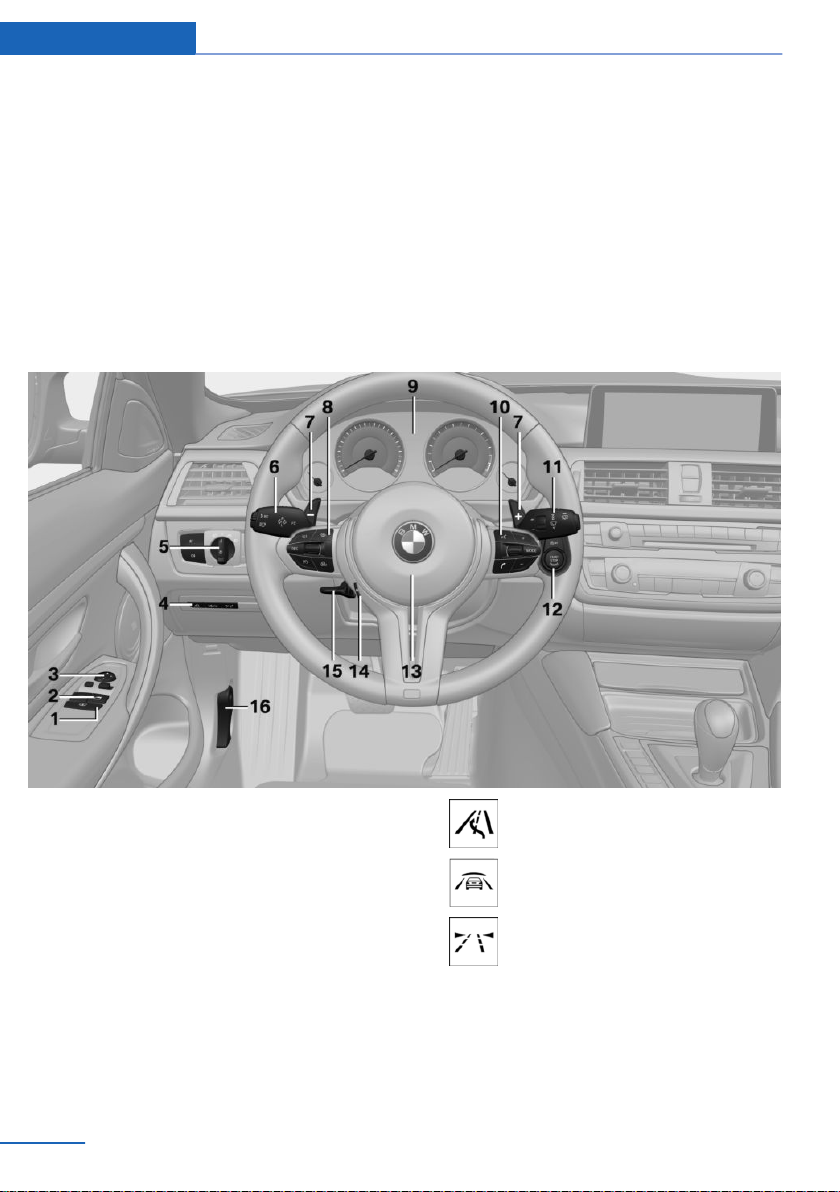
All around the steering wheel
the selected options or country versions. This
also applies to safety-related functions and
systems. The respectively applicable country
provisions must be observed when using the
respective features and systems.
1 Roller sunblinds 47
2 Power windows 46
3 Exterior mirror operation 55
4 Glove compartment on the driver's
side 147
Driver assistance systems
14
Online Edition for Part no. 01 40 2 960 786 - II/15
Active Blind Spot Detec‐
tion 111
Intelligent Safety 104
Lane departure warning 110
5 Lights
Page 19
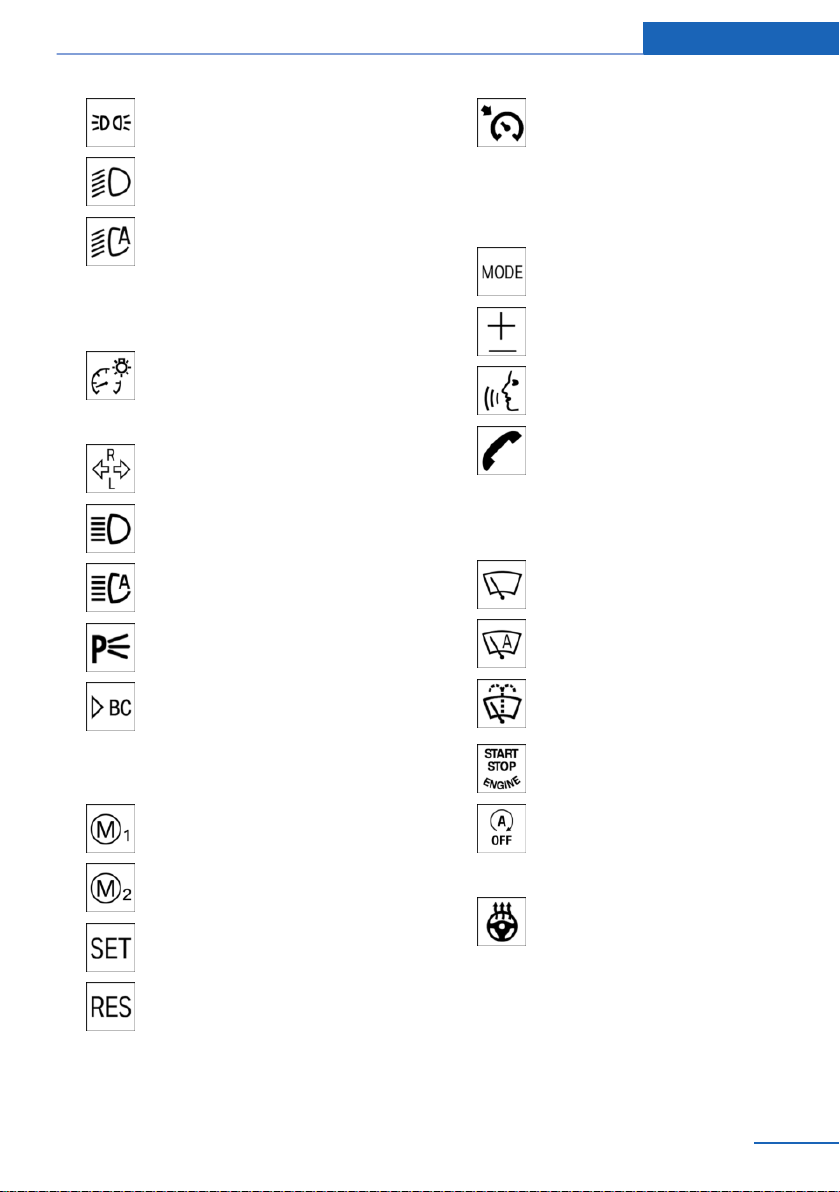
Cockpit At a glance
Parking lights 93
Low beams 93
Automatic headlight con‐
trol 94
Daytime running lights 94
Adaptive Light Control 94
High-beam Assistant 95
Instrument lighting 96
6 Steering column stalk, left
Turn signal 67
High beams, head‐
light flasher 67
High-beam Assistant 95
Roadside parking lights 94
Cruise control on/off, inter‐
rupt 120
Cruise control rocker switch 120
9 Instrument cluster 76
10 Steering wheel buttons, right
Entertainment source
Volume
Voice activation 27
Telephone, see user's manual for
Navigation, Entertainment and
Communication
Thumbwheel for selection lists 86
11 Steering column stalk, right
Wiper 67
Rain sensor 68
On-board computer 86
7 Shift paddles 72
8 Steering wheel buttons, left
M Drive 1 activation 114
M Drive 2 activation 114
Store speed 120
Resume speed 120
Online Edition for Part no. 01 40 2 960 786 - II/15
Clean the windshields and head‐
lights 69
12 Start/stop the engine and switch
the ignition on/off 63
Auto Start/Stop function 64
13 Horn, total area
14 Steering wheel heating 57
15 Adjust steering wheel 57
16 Unlock hood 181
15
Page 20
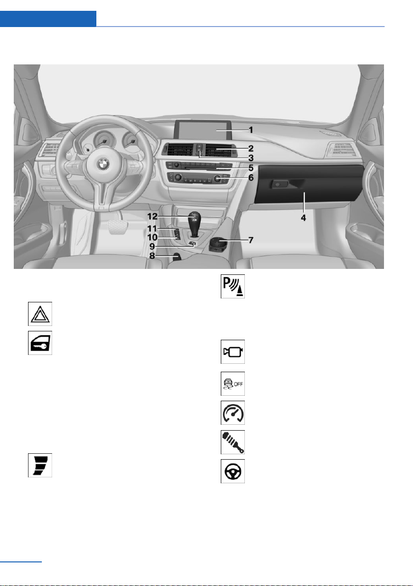
At a glance Cockpit
All around the center console
1 Control Display 18
2 Ventilation 137
3 Hazard warning system 199
Central locking system 39
4 Glove compartment 147
5 Radio/CD/Multimedia, see user's manual
for Navigation, Entertainment and Commu‐
nication
6 Climate control 134
7 Controller with buttons 18
8 Parking brake 66
9 Drivelogic 72
10 PDC Park Distance Control 122
Rearview camera 124
Parking assistant 130
Surround View 124
Side View 127
11 DSC Dynamic Stability Con‐
trol 115
Engine Dynamics 74
Adaptive M chassis 117
Servotronic 118
12 M double-clutch transmission selector
lever 70
16
Online Edition for Part no. 01 40 2 960 786 - II/15
Page 21
Manual transmission selector lever 70
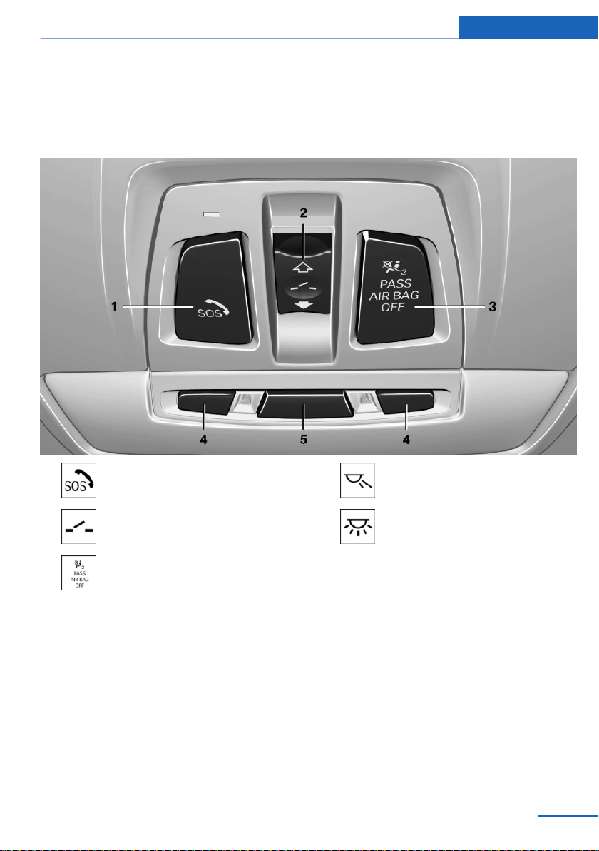
All around the roofliner
Cockpit At a glance
1 Intelligent Emergency Re‐
quest 199
2 Glass sunroof, powered 47
3 Indicator lamp, front-seat pas‐
senger airbag 100
Online Edition for Part no. 01 40 2 960 786 - II/15
4 Reading lights 96
5 Interior lights 96
17
Page 22
At a glance iDrive
iDrive
Vehicle features and options
This chapter describes all standard, countryspecific and optional features offered with the
series. It also describes features that are not
necessarily available in your car, e. g., due to
the selected options or country versions. This
also applies to safety-related functions and
systems. The respectively applicable country
provisions must be observed when using the
respective features and systems.
The concept
The iDrive combines the functions of many
switches. Thus, these functions can be oper‐
ated from a central location.
Using the iDrive during a trip
To avoid becoming distracted and pos‐
ing an unnecessary hazard to your vehicle's
occupants and to other traffic, never attempt
to use the controls or enter information unless
traffic and road conditions allow it.◀
Control Display
Hints
▷ To clean the Control Display, follow the
care instructions.
▷ Do not place objects close to the Control
Display; otherwise, the Control Display can
be damaged.
▷ In the case of very high temperatures on
the Control Display, e.g. due to intense so‐
lar radiation, the brightness may be re‐
duced down to complete deactivation.
Once the temperature is reduced, e.g.
through shadow or climate control system,
the normal functions are re-established.
Switching on
Switch on the ignition.
1.
2. Press the controller.
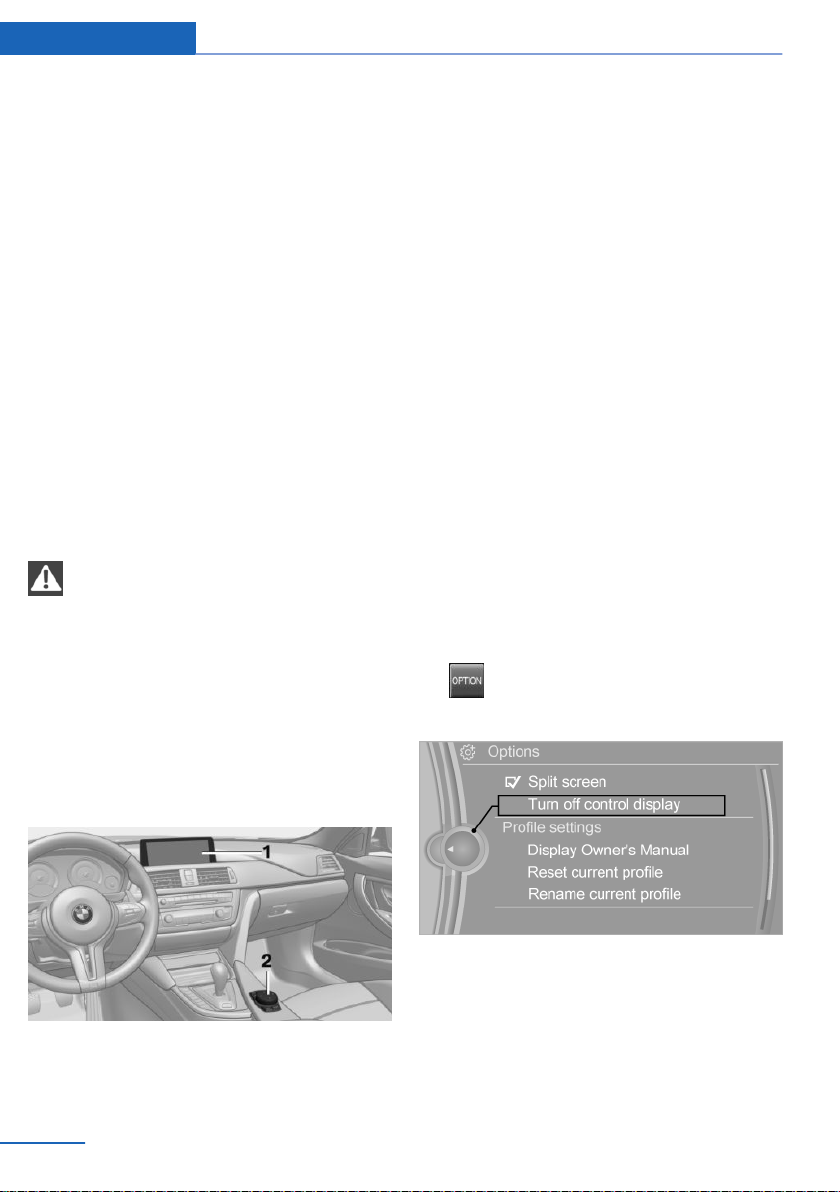
Switch off
1. Press button.
2. "Turn off control display"
Control elements at a glance
Control elements
1 Control Display
2 Controller with buttons and, depending on
the equipment version, with touchpad
18
Online Edition for Part no. 01 40 2 960 786 - II/15
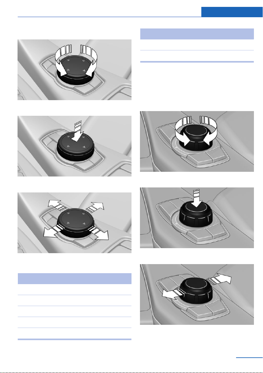
Controller with navigation system
The buttons can be used to open the menus
directly. The controller can be used to select
menu items and enter the settings.
Some iDrive functions can be operated using
the touchpad on the controller.
Page 23
iDrive At a glance
1. Turn.
2. Press.
3. Move in four directions.
Press button Function
BACK Displays the previous panel.
OPTION Opens the Options menu.
Controller without navigation system
The buttons can be used to open the menus
directly. The controller can be used to select
menu items and enter the settings.
1. Turn.
2. Press.
Buttons on controller
Press button Function
MENU Open the main menu.
RADIO Opens the Radio menu.
MEDIA Opens the Multimedia menu.
NAV Opens the Navigation menu.
TEL Opens the phone menu.
Online Edition for Part no. 01 40 2 960 786 - II/15
3. Move in two directions.
19
Page 24
At a glance iDrive
Buttons on controller
Press button Function
MENU Open the main menu.
Audio Open audio menu last listened
to, switch between audio me‐
nus.
TEL Opens the phone menu.
BACK Open previous panel.
OPTION Opens the Options menu.
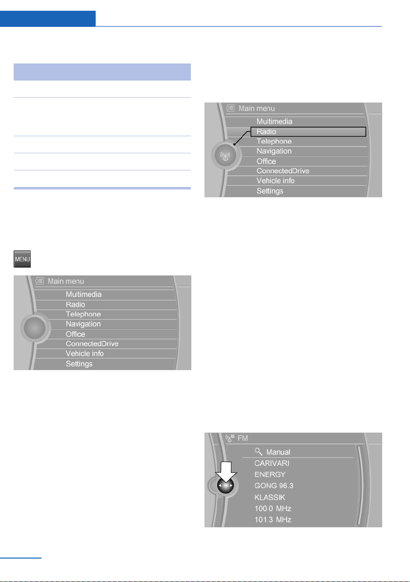
Operating concept
Opening the main menu
Press button.
The main menu is displayed.
All iDrive functions can be called up via the
main menu.
Selecting menu items
Highlighted menu items can be selected.
1. Turn the controller until the desired menu
item is highlighted.
2. Press the controller.
Menu items in the Owner's Manual
In the Owner's Manual, menu items that can be
selected are set in quotation marks, e.g.,
"Settings".
Changing between panels
After a menu item is selected, e.g., "Radio", a
new panel is displayed. Panels can overlap.
▷ Move the controller to the left.
Closes current display and shows previous
display.
Reopens previous display by pressing
BACK button. In this case, the current
panel is not closed.
▷ Move the controller to the right.
Opens new display on top of previous
screen.
20
Online Edition for Part no. 01 40 2 960 786 - II/15
Page 25
iDrive At a glance
White arrows pointing to the left or right indi‐
cate that additional panels can be opened.
Display of an opened menu
When selecting a menu, it generally opens with
the panel that was last selected in that menu.
To display the first panel of a menu:
▷ Move the controller to the left repeatedly
until the first panel is displayed.
▷ Press the menu button on the controller
twice.
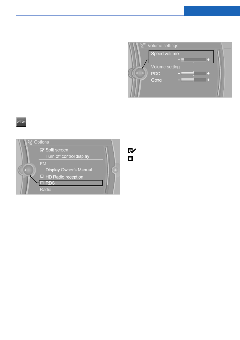
Opening the Options menu
Press button.
The "Options" menu is displayed.
Additional options: move the controller to the
right repeatedly until the "Options" menu is
displayed.
Options menu
The "Options" menu consists of various areas:
▷ Screen settings, e.g., "Split screen".
This area remains unchanged.
▷ Control options for the selected main
menu, e.g., for "Radio".
▷ If applicable, further operating options for
the selected menu, e.g., "Store station".
2. Turn the controller until the desired setting
is displayed.
3. Press the controller.
Activating/deactivating the functions
Several menu items are preceded by a check‐
box. It indicates whether the function is acti‐
vated or deactivated. Selecting the menu item
activates or deactivates the function.
Function is activated.
Function is deactivated.
Touchpad
Some iDrive functions can be operated using
the touchpad on the controller:
Selecting functions
"Settings"
1.
2. "Touchpad"
3. Select the desired function.
▷ "Speller": enter letters and numbers.
▷ "Interactive map": viewing the interac‐
tive map.
▷ "Browser": enter Internet addresses.
▷ "Audio feedback": pronounces entered
letters and numbers.
Changing settings
Select a field.
1.
Entering letters and numbers
Entering letters requires some practice at the
beginning. When entering, pay attention to the
following:
Online Edition for Part no. 01 40 2 960 786 - II/15
21
Page 26
At a glance iDrive
▷ For the input of upper/lower case letters
and numbers, it may be necessary to reel
via the controller to the corresponding In‐
put mode, refer to page 25, e.g. when the
spelling of upper and lower case letters is
identical.
▷ Enter characters as they are displayed on
the Control Display.
▷ Always enter associated characters, such
as accents or periods so that the letter can
be clearly recognized. Possible input de‐
pends on the set language. Where neces‐
sary, enter special characters via the con‐
troller.
▷ To delete a character, slide to the left on
the touchpad.
▷ To enter a blank space, slide to the right in
the center of the touchpad.
▷ To enter a hyphen, slide to the right in the
upper area of the touchpad.
▷ To enter an underscore, swipe to the right
in the lower area of the touchpad.
Using interactive map and Internet
Via touch-pad move the interactive map in the
navigation system and Internet sites.
Function Controls
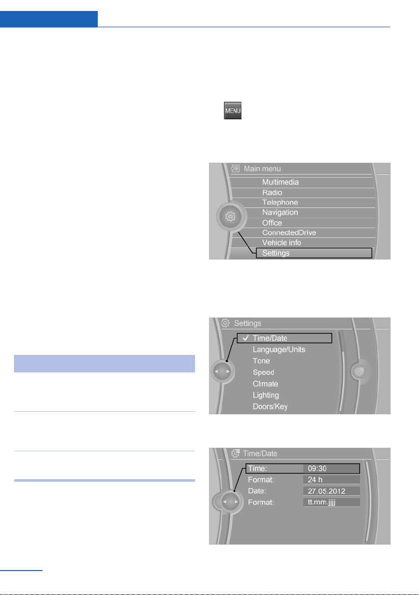
Example: setting the clock
Setting the clock
On the Control Display:
1.
2. Turn the controller until "Settings" is high‐
3. If necessary, move the controller to the left
4. Turn the controller until "Time/Date" is
Press button. The main menu is dis‐
played.
lighted, and then press the controller.
to display "Time/Date".
highlighted, and then press the controller.
Move interactive map or
Internet sites.
Enlarge/shrink interactive
map or Internet sites.
Display the menu or open
a link in the Internet.
Swipe into re‐
spective direc‐
tion.
Drag in or out on
the touchpad with
fingers.
Tap once.
Changing settings
You may change control display settings via
touchpad. Swipe left or right accordingly.
22
Online Edition for Part no. 01 40 2 960 786 - II/15
5. Turn the controller until "Time:" is high‐
lighted, and then press the controller.
Page 27
iDrive At a glance
6. Turn the controller to set the hours and
press the controller.
7. Turn the controller to set the minutes and
press the controller.
Status information
Status field
The following information is displayed in the
status field at the top right:
▷ Time.
▷ Current entertainment source.
▷ Sound output, on/off.
▷ Wireless network reception strength.
▷ Phone status.
▷ Traffic bulletin reception.
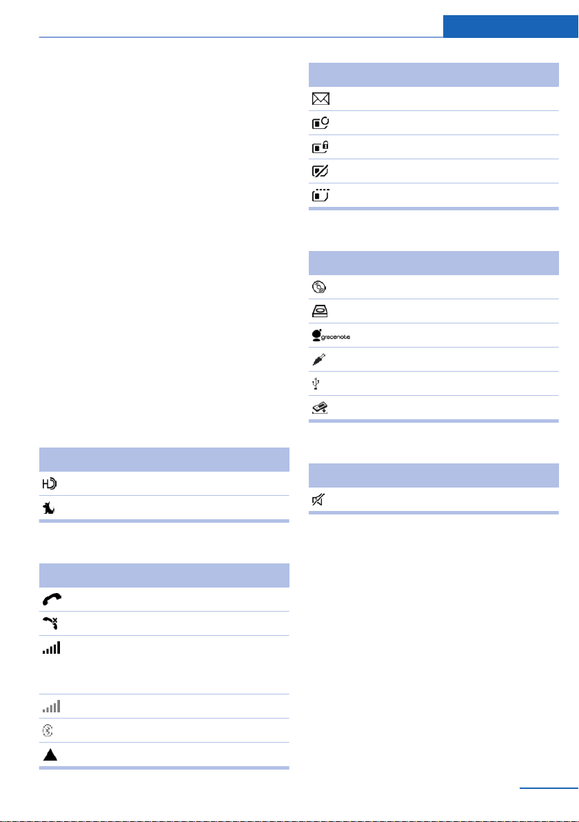
Status field symbols
The symbols are grouped as follows.
Radio symbols
Symbol Meaning
HD Radio station is being received.
Satellite radio is switched on.
Symbol Meaning
Text message was received.
Check the SIM card.
SIM card is blocked.
SIM card is missing.
Enter PIN.
Entertainment symbols
Symbol Meaning
CD/DVD player.
Music collection.
Gracenote® database.
AUX-IN port.
USB audio interface.
Mobile phone audio interface.
Additional symbols
Symbol Meaning
Spoken instructions are turned off.
Telephone symbols
Symbol Meaning
Incoming or outgoing call.
Missed call.
Wireless network reception
strength.
Symbol flashes: network search.
Wireless network is not available.
Bluetooth is switched on.
Roaming is active.
Online Edition for Part no. 01 40 2 960 786 - II/15
Split screen
General information
Additional information can be displayed on the
right side of the split screen, e.g., information
from the on-board comupter.
In the divided screen view, the so-called split
screen, this information remains visible even
when you change to another menu.
23
Page 28
At a glance iDrive
Switching the split screen on and off
On the Control Display:
1.
2. "Split screen"
Press button.
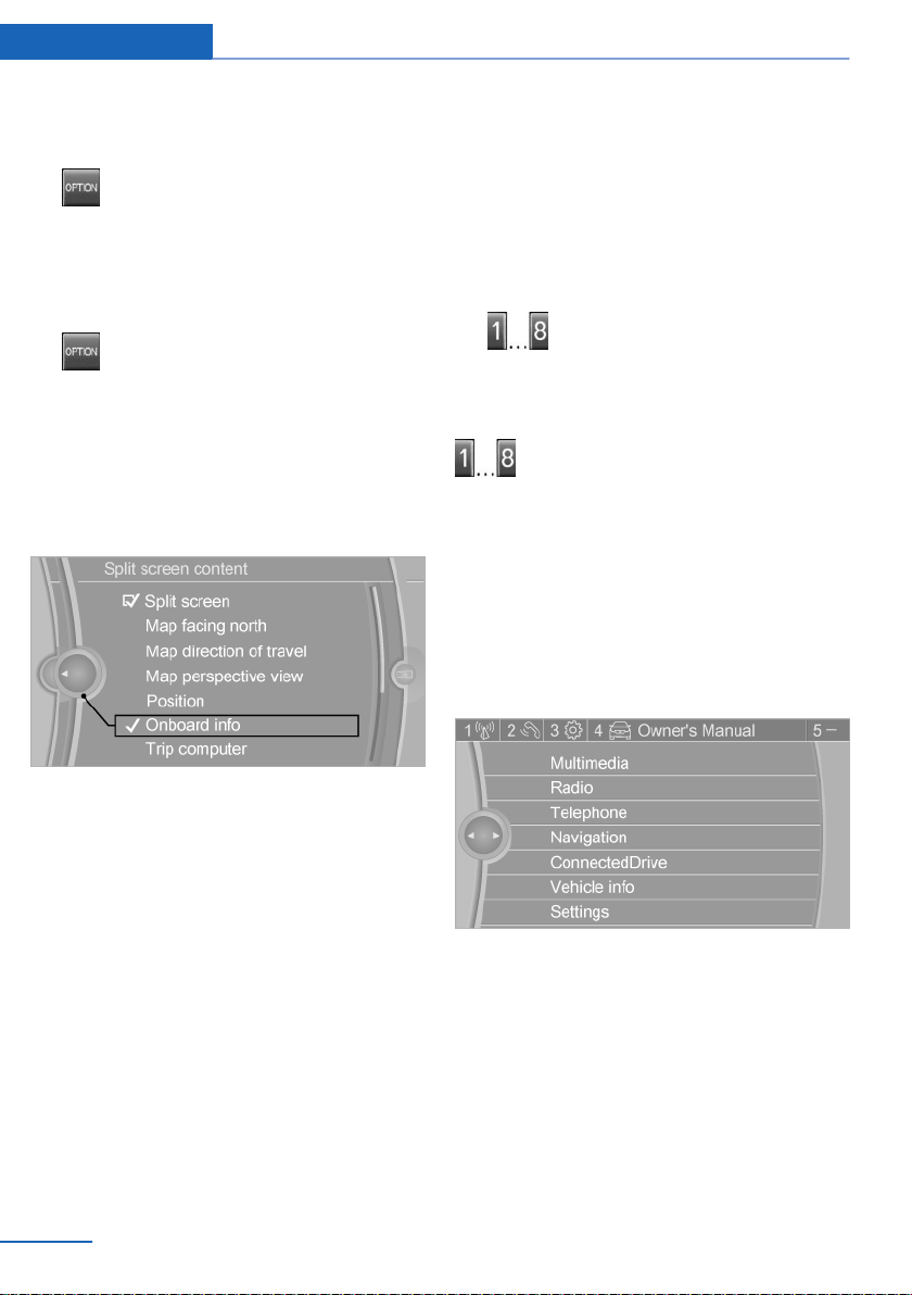
Selecting the display
On the Control Display:
1.
2. "Split screen"
3. Move the controller until the split screen is
4. Press the controller or select "Split screen
5. Select the desired menu item.
Press button.
selected.
content".
Without navigation system and
telephone
Only radio stations can be stored on the but‐
tons, refer to user's manual for Navigation, En‐
tertainment, Communication.
Saving a function
1. Highlight the function via the iDrive.
2.
Press and hold the desired button,
until a signal sounds.
Running a function
Press button.
The function will work immediately.
This means, e.g., that the number is dialed
when a phone number is selected.
Displaying the button assignment
Touch buttons with bare fingers. Do not wear
gloves or use objects.
The key assignment is displayed at top edge of
screen.
Programmable memory buttons
General information
The iDrive functions can be stored on the pro‐
grammable memory buttons and called up di‐
rectly, e.g., radio stations, navigation destina‐
tions, phone numbers and menu entries.
Settings are stored for the profile currently in
use.
24
Online Edition for Part no. 01 40 2 960 786 - II/15
Deleting the button assignments
Press buttons 1 and 8 simultaneously for
1.
approx. five seconds.
2. "OK"
Page 29
iDrive At a glance
Deleting personal in the vehicle
The concept
Depending on the usage, the vehicle saves
personal data, such as stored radio stations.
These personal data can be permanently de‐
leted through iDrive.
General information
Depending on the equipment package, the fol‐
lowing data can be deleted:
▷ Personal Profile settings.
▷ Stored radio stations.
▷ Stored Favorites buttons.
▷ Travel and computer information.
▷ Music collection.
▷ Navigation, e.g. stored destinations.
▷ Phone book.
▷ Online data, e.g. Favorites, cookies.
▷ Voice notes.
▷ Login accounts.
▷ RemoteApp smartphone tethering.
Altogether, the deletion of the data can take up
to 30 minutes.
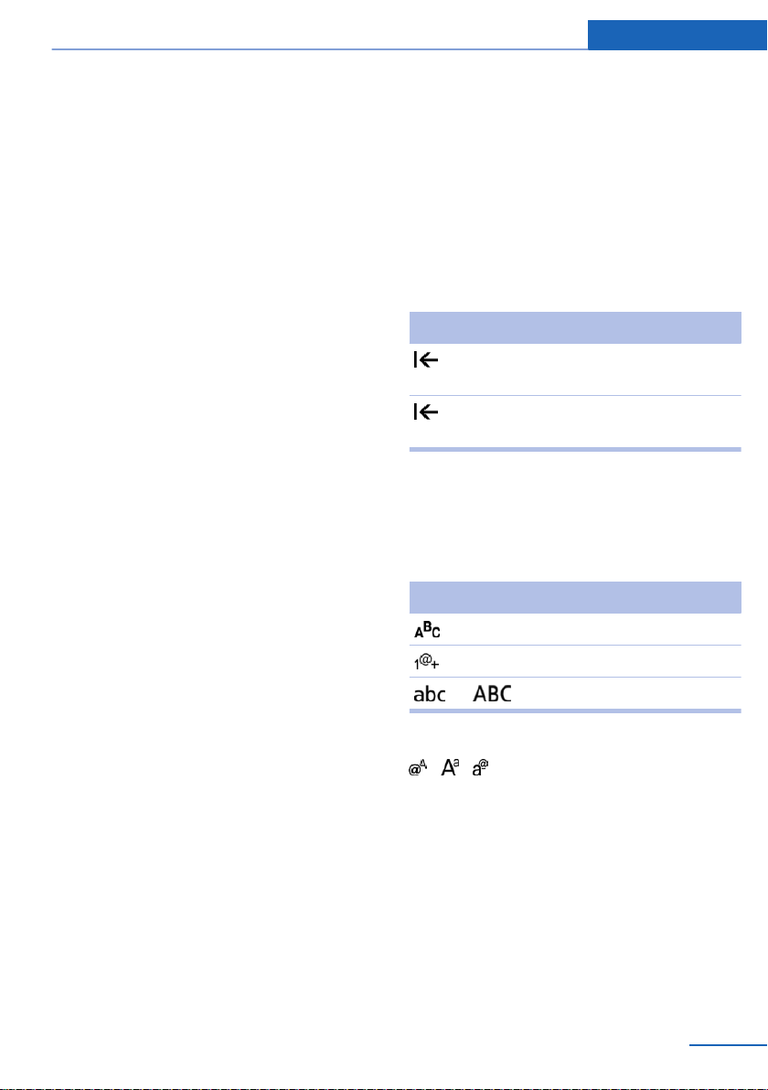
Entering letters and numbers
General information
On the Control Display:
1. Turn the controller: select letters or num‐
bers.
2. Select additional letters or numbers if
needed.
3. "OK": confirm the entry.
Symbol Function
Press the controller: delete the let‐
ter or number.
Press the controller for an extended
period: delete all letters or numbers.
Switching between cases, letters and
numbers
Depending on the menu, you can reel between
entering upper and lower case, letters and
numbers:
Symbol Function
Enter the letters.
Enter the numbers.
Functional requirement
Data can only be deleted while stationary.
Deleting data
Heed and follow the instructions on the Con‐
trol Display.
Switch on the ignition.
1.
2. "Settings"
3. Open "Options".
4. "Delete personal data"
5. "Continue"
6. "OK"
Online Edition for Part no. 01 40 2 960 786 - II/15
or Tip controller up.
Without navigation system
Select the symbol.
Entry comparison
Entering names and addresses: choice is nar‐
rowed down with every letter entered and let‐
ters may be added automatically.
Entries are continuously compared with data
stored in the vehicle.
▷ Only those letters are offered during input
for which data is available.
25
Page 30

At a glance iDrive
▷ Target search: names of locations may be
entered in languages available through
Control Display.
26
Online Edition for Part no. 01 40 2 960 786 - II/15
Page 31

Voice activation system At a glance
Voice activation system
Vehicle features and options
This chapter describes all standard, countryspecific and optional features offered with the
series. It also describes features that are not
necessarily available in your car, e. g., due to
the selected options or country versions. This
also applies to safety-related functions and
systems. The respectively applicable country
provisions must be observed when using the
respective features and systems.
The concept
▷ Most functions displayed on the Control
Display can be operated by voice com‐
mands via the voice activation system. The
system supports you with announcements
during input.
▷ Functions that can only be used when the
vehicle is stationary cannot be used via the
voice activation system.
▷ The system uses a special microphone on
the driver's side.
▷ ›...‹ Verbal instructions in the Owner's
Manual to use with the voice activation
system.
Requirements
Via the Control Display, set a language that is
also supported by the voice activation system
so that the spoken commands can be identi‐
fied.
Set the language, refer to page 89.
Using voice activation
Activating the voice activation system
1.
2. Wait for the signal.
3. Say the command.
This symbol in the instrument cluster indi‐
cates that the voice activation system is active.
If no other commands are available, use func‐
tion via iDrive.
Press button on the steering
wheel.
A command that is recognized by the voice
activation system is announced and dis‐
played in the instrument cluster.
Terminating the voice activation
system
Briefly press the button on the steer‐
ing wheel or ›Cancel‹.
Possible commands
Most menu items on the Control Display can
be voiced as commands.
The available commands depend on the menu
that is currently displayed on the Control Dis‐
play.
There are short commands for many functions.
You may select lists such as phone lists via
voice activation. Read these lists out loud ex‐
actly as they show in the respective list.
Having possible commands read aloud
You can have available commands read out
loud for you: ›Voice commands‹
E. g. if the "Settings" menu is displayed, the
commands for the settings are read out loud.
Online Edition for Part no. 01 40 2 960 786 - II/15
27
Page 32

At a glance Voice activation system
Executing functions using short
commands
Execute functions on the main menu via short
commands. It almost doesn't matter which
menu item is selected, e.g., ›Vehicle status‹.
List of short commands for the voice activation
system, see Navigation, Entertainment, Com‐
munication Owner's Manual.
Help dialog for the voice activation
system
Calling up help dialog: ›Help‹
Additional commands for the help dialog:
▷ ›Help with examples‹: announces informa‐
tion about the current operating options
and the most important commands for
them.
▷ ›Help with voice activation‹: information
about the principle of operation for the
voice activation system is announced.
One example: open the tone settings
2.
3. ›Tone‹
Press button on the steering
wheel.
Setting the voice dialog
Set system to standard dialog or use a short
version.
The short version of the voice dialog plays
back short messages in abbreviated form.
1. "Settings"
2. "Language/Units"
3. "Speech type:"
4. Select setting.
Via the main menu
The commands of the menu items are spoken
just as they are selected via the controller.
Turn on the Entertainment sound output if
1.
needed.
2.
3. ›Radio‹
4. ›Tone‹
Press button on the steering
wheel.
Via short command
The desired tone settings can also be started
via a short command.
Turn on the Entertainment sound output if
1.
needed.
28
Online Edition for Part no. 01 40 2 960 786 - II/15
Adjusting the volume
Turn the volume button while giving an in‐
struction until the desired volume is set.
▷ The volume remains constant even if the
volume of other audio sources is changed.
▷ The volume is stored for the profile cur‐
rently in use.
Hints on Emergency Requests
Do not use the voice activation system to ini‐
tiate an Emergency Request. In stressful situa‐
tions, the voice and vocal pitch can change.
Page 33

This can unnecessarily delay the establish‐
ment of a phone connection.
Instead, use the SOS button, refer to
page 199, close to the interior mirror.
Environmental conditions
▷ Say the commands, numbers, and letters
smoothly and with normal volume, empha‐
sis, and speed.
▷ Always say commands in the language of
the voice activation system.
▷ Keep the doors, windows, and glass sun‐
roof closed to prevent noise interference.
▷ Avoid making other noise in the vehicle
while speaking.
Voice activation system At a glance
Online Edition for Part no. 01 40 2 960 786 - II/15
29
Page 34

At a glance Integrated Owner's Manual in the vehicle
Integrated Owner's Manual in the vehicle
Vehicle features and options
This chapter describes all standard, countryspecific and optional features offered with the
series. It also describes features that are not
necessarily available in your car, e. g., due to
the selected options or country versions. This
also applies to safety-related functions and
systems. The respectively applicable country
provisions must be observed when using the
respective features and systems.
Integrated Owner's Manual in the vehicle
The Integrated Owner's Manual can be dis‐
played on the Control Display. It specifically
describes features and functions found in the
vehicle.
Components of the Integrated
Owner's Manual
The Integrated Owner's Manual consists of
three parts, which offer various levels of infor‐
mation or possible access.
Quick Reference Guide
The Quick Reference Guide provides informa‐
tion how to operate the car, how to use basic
vehicle functions or what to do in case of a
breakdown. This information can also be dis‐
played while driving.
Search by images
Image search provides information and de‐
scriptions. This is helpful when the terminol‐
ogy for a feature is not at hand.
Select components
1.
2. Turn the controller: open "Vehicle info".
3. Press the controller.
4. Selecting desired range:
Press button.
▷ "Quick reference"
▷ "Search by pictures"
▷ "Owner's Manual"
Leafing through the Owner's Manual
Page by page with link access
Turn the controller until the next or previous
page is displayed.
Page by page without link access
Scroll through the pages directly while skip‐
ping the links.
Highlight the symbol once. Now simply press
the controller to browse from page to page.
Scroll back.
Scroll forward.
Owner's Manual
Search for information and descriptions by en‐
tering terms selected from the index.
30
Online Edition for Part no. 01 40 2 960 786 - II/15
Page 35

Integrated Owner's Manual in the vehicle At a glance
Context help - Owner's Manual to the
temporarily selected function
You may open the relevant information di‐
rectly.
Opening via the iDrive
To move directly from the application on the
Control Display to the Options menu:
1.
2. "Display Owner's Manual"
Press button or move the controller
to the right repeatedly until the "Options"
menu is displayed.
Opening when a Check Control
message is displayed
Directly from the Check Control message on
the Control Display:
"Display Owner's Manual"
Changing between a function and the
Owner's Manual
To reel from a function, e. g., radio, to the
Owner's Manual on the Control Display and to
alternate between the two displays:
Programmable memory buttons
General information
The Owner's Manual can be stored on the pro‐
grammable memory buttons and called up di‐
rectly.
Storing
1. "Owner's Manual" Select via the iDrive.
2.
Press selected button for more
than 2 seconds.
Executing
Press button.
The Owner's Manual is displayed im‐
mediately.
1. Press button or move the controller
to the right repeatedly until the "Options"
menu is displayed.
2. "Display Owner's Manual"
3. Select the desired page in the Owner's
Manual.
4.
5.
To alternate permanently between the last dis‐
played function and the Owner's Manual re‐
peat steps 4 & 5. Opens a new display every
time.
Press button again to return to last
displayed function.
Press button to return to the page of
the Owner's Manual displayed last.
Online Edition for Part no. 01 40 2 960 786 - II/15
31
Page 36

Online Edition for Part no. 01 40 2 960 786 - II/15
Page 37

Controls
This chapter is intended to provide you with
information that will give you complete control of
your vehicle. All features and accessories that
are useful for driving and your safety, comfort
and convenience are described here.
Online Edition for Part no. 01 40 2 960 786 - II/15
Page 38

Controls Opening and closing
Opening and closing
Vehicle features and options
This chapter describes all standard, countryspecific and optional features offered with the
series. It also describes features that are not
necessarily available in your car, e. g., due to
the selected options or country versions. This
also applies to safety-related functions and
systems. The respectively applicable country
provisions must be observed when using the
respective features and systems.
Remote control/key
General information
The vehicle is supplied with two remote con‐
trols with integrated key.
Every remote control holds a replaceable bat‐
tery.
You may set the key functions depending on
the optional features and country-specific ver‐
sion. For Settings, refer to page 43.
The vehicle stores personal settings for every
remote control. Personal Profile, refer to
page 35.
The remote controls hold information on re‐
quired maintenance. Service data in the re‐
mote control, refer to page 188
Overview
1 Unlocking
2 Locking
3 Opening the trunk lid
4 Panic mode
Integrated key
Press button, arrow 1, and remove the key, ar‐
row 2.
The integrated key fits the following locks:
▷ Driver's door.
▷ Glove compartment on the front passenger
side.
34
The front passenger glove compartment con‐
tains a switch for separately securing the trunk
lid, refer to page 41.
Online Edition for Part no. 01 40 2 960 786 - II/15
Page 39

Opening and closing Controls
Replacing the battery
1. Remove integrated key from remote con‐
trol.
2. Push in the catch with the key, arrow 1.
3. Remove the cover of the battery compart‐
ment, arrow 2.
4. Insert a battery of the same type with the
positive side facing up.
5. Press the cover closed.
Take the used battery to a recycling
center or to your service center.
New remote controls
New remote controls are available from the
service center.
Loss of the remote controls
Lost remote controls can be disabled by your
service center.
Emergency detection of remote
control
It is possible to switch on the ignition or start
the engine in situations such as the following:
▷ Interference of radio transmission to re‐
mote control by external sources e.g., by
radio masts.
▷ Empty battery in remote control.
▷ Interference from radio transmissions
through mobile devices in close proximity
to remote control.
▷ Interference of radio transmission by
charger while charging items such as mo‐
bile devices in the vehicle.
A Check Control message is displayed if an at‐
tempt is made to switch on the ignition or start
the engine.
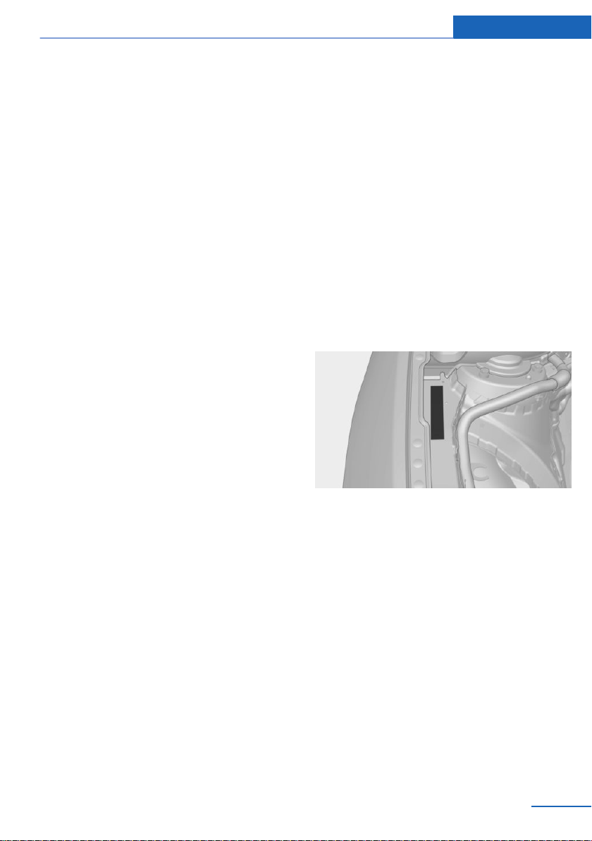
Starting the engine with emergency
detection of the remote control
M double-clutch transmission: if a correspond‐
ing Check Control message appears, hold the
remote control, as shown, against the marked
area on the steering column and press the
Start/Stop button within 10 seconds while
pressing the brake.
Manual transmission: if a corresponding Check
Control message appears, hold the remote
control, as shown, against the marked area on
the steering column and press the Start/Stop
button within 10 seconds while pressing the
clutch pedal.
If the remote control is not recognized: slightly
change the height position of the remote con‐
trol and repeat the procedure.
Personal Profile
The concept
Personal Profile provides three profiles, using
which personal vehicle settings can be stored.
Every remote control has one of these profiles
assigned.
If the vehicle is unlocked using a remote con‐
trol, the assigned personal profile will be acti‐
Online Edition for Part no. 01 40 2 960 786 - II/15
35
Page 40

Controls Opening and closing
vated. All settings stored in the profile are au‐
tomatically applied.
If several drivers use their own remote control,
the vehicle will adjust the personal settings
during unlocking. These settings are also re‐
stored, if the vehicle has been used in the
meantime by a person with a different remote
control.
Changes to the settings are automatically
saved in the personal profile.
Three personal profiles and a guest profile can
be created.
Adjusting
The settings for the following systems and
functions are saved in the active profile. The
scope of storable settings is country- and
equipment-dependable.
▷ Unlocking and locking.
▷ Lights.
▷ Climate control.
▷ Radio.
▷ Instrument cluster.
▷ Programmable memory buttons.
▷ Volumes, tone.
▷ Control Display.
▷ Navigation.
▷ Park Distance Control PDC.
▷ Rearview camera
▷ Side View.
▷ Head-up Display.
▷ M Drive: configurations.
▷ Driver's seat position, exterior mirror posi‐
tion, steering wheel position.
▷ Cruise control.
▷ Intelligent Safety.
▷ Active Blind Spot Detection.
Profile management
Opening profiles
Regardless of the remote control in use a dif‐
ferent profile may be activated.
1. "Settings"
2. "Profiles"
3. Select a profile.
▷ All settings stored in the called-up profile
are automatically applied.
▷ The called-up profile is assigned to the re‐
mote control being used at the time.
▷ If the profile is already assigned to a differ‐
ent remote control, this profile will apply to
both remote controls. It cannot be differen‐
tiated anymore between the settings for
the two remote controls.
Renaming profiles
A personal name can be assigned to every pro‐
file to avoid confusion between the profiles.
"Settings"
1.
2. "Profiles"
3. "Options"
4. "Rename current profile"
Resetting profiles
The settings of the active profile are reset to
their default values.
"Settings"
1.
2. "Profiles"
3. "Options"
4. "Reset current profile"
Exporting profiles
Most settings of the active profile can be ex‐
ported.
This can be helpful for securing and retrieving
personal settings, before delivering the vehicle
to a workshop, e.g. Profiles can be taken to an‐
36
Online Edition for Part no. 01 40 2 960 786 - II/15
Page 41

Opening and closing Controls
other vehicle equipped with the Personal Pro‐
file function.
The following export options are available:
▷ Via BMW Online.
▷ Via the USB port to a USB device.
Popular file systems for USB devices are
supported. FAT32 and exFAT are the rec‐
ommended formats for profile export.
Other formats may not support the export.
1. "Settings"
2. "Profiles"
3. "Export profile"
4. BMW Online: "BMW Online"
USB interface: "USB device"
Importing profiles
Profiles exported via BMW Online can also be
imported via BMW Online.
Profiles stored on a USB device can be im‐
ported via the USB interface.
Existing settings are overwritten with the im‐
ported profile.
"Settings"
1.
2. "Profiles"
3. "Import profile"
4. BMW Online: "BMW Online"
USB interface: "USB device"
Using the guest profile
The guest profile is for individual settings that
are saved in none of the three personal pro‐
files.
This can be useful for drivers who are using
the vehicle temporarily and do not have their
own profile.
"Settings"
1.
2. "Profiles"
3. "Guest"
The guest profile cannot be renamed. It is not
assigned to the current remote control.
Display profile list during start
The profile list can be displayed during each
start to select the desired profile.
1. "Settings"
2. "Profiles"
3. "Options"
4. "Display user list at startup"
Using the remote control
Note
Take the remote control with you
People or animals left unattended in a
parked vehicle can lock the doors from the in‐
side. Always take the remote control with you
when leaving the vehicle so that the vehicle
can then be opened from the outside.◀
Unlocking
Press button on the remote control.
▷ All doors, the tailgate, and the fuel filler flap
are being unlocked.
▷ Interior lamps and courtesy lamps are acti‐
vated. This function is not available, if the
interior lamps were switched off manually.
▷ The welcome lamps are switched on, if this
function was activated.
▷ Exterior mirrors folded through convenient
closing are folded open.
You can set how the vehicle is to be unlocked.
For Settings, refer to page 43.
The alarm system, refer to page 44, is dis‐
armed.
Convenient opening
Press and hold this button on the re‐
mote control after unlocking.
Online Edition for Part no. 01 40 2 960 786 - II/15
37
Page 42

Controls Opening and closing
The windows and the glass sunroof are
opened, as long as the button on the remote
control is pressed.
Locking
Locking from the outside
Do not lock the vehicle from the outside
with people inside the car, as the vehicle can‐
not be unlocked from inside without special
knowledge.◀
The driver's door must be closed.
Press button on the remote control.
All doors, the tailgate, and the fuel filler flap are
being locked.
The alarm system, refer to page 44, is armed.
Switching on interior lights and
courtesy lights
Press button on the remote control with
the vehicle locked.
This function is not available, if the interior
lamps were switched off manually.
If the button is pressed again within 10 sec‐
onds after vehicle was locked, the interior mo‐
tion sensor and tilt alarm sensor of the antitheft warning system, refer to page 45, are
turned off. After locking, wait 10 seconds be‐
fore pressing the button again.
Panic mode
You can trigger the alarm system if you find
yourself in a dangerous situation.
Press button on the remote control for
at least 3 seconds.
To reel off the alarm: press any button.
The trunk lid opens, regardless of whether the
vehicle was previously locked or unlocked.
During opening, the trunk lid pivots back and
up. Ensure that adequate clearance is available
before opening.
Depending on the features and the country
version, it is also possible to have door un‐
locked. Create the settings, refer to page 43.
If the doors were not unlocked, the trunk lid is
locked again as soon as it closes.
Do not place the remote control in the
cargo area
Take the remote control with you and do not
leave it in the cargo area; otherwise, the re‐
mote control is locked inside the vehicle when
the trunk lid is closed.◀
Malfunction
Remote control detection by the vehicle can
among others be malfunctioning under the fol‐
lowing circumstances:
▷ The battery of the remote control is dis‐
charged. Replace the battery, refer to
page 35.
▷ Interference of the radio connection from
transmission towers or other equipment
with high transmit power.
▷ Shielding of the remote control due to
metal objects.
▷ Interference of the radio connection from
mobile phones or other electronic devices
in direct proximity.
Do not transport the remote control together
with metal objects or electronic devices.
In the case of interference, the vehicle can also
be unlocked and locked from the outside with‐
out remote control, refer to page 39.
Opening the trunk lid
Press button on the remote control for
approx. 1 second.
38
For US owners only
The transmitter and receiver units comply with
part 15 of the FCC/Federal Communication
Online Edition for Part no. 01 40 2 960 786 - II/15
Page 43

Commission regulations. Operation is gov‐
erned by the following:
FCC ID:
▷ LX8766S.
▷ LX8766E.
▷ LX8CAS.
▷ LX8CAS2.
▷ MYTCAS4.
Compliance statement:
This device complies with part 15 of the FCC
Rules. Operation is subject to the following
two conditions:
▷ This device may not cause harmful inter‐
ference, and
▷ this device must accept any interference
received, including interference that may
cause undesired operation.
Any unauthorized modifications or changes to
these devices could void the user's authority to
operate this equipment.
Without remote control
From the outside
Locking from the outside
Do not lock the vehicle from the outside
with people inside the car, as the vehicle can‐
not be unlocked from inside without special
knowledge.◀
Opening and closing Controls
Unlock or lock the driver's door via the door
lock using the integrated key, refer to page 34.
The other doors must be unlocked or locked
from the inside.
Alarm system
The alarm system is not armed if the vehicle is
locked with the integrated key.
The alarm system is triggered when the door is
opened, if the vehicle was unlocked via the
door lock.
In order to terminate this alarm, unlock vehicle
with the remote control or switch on the igni‐
tion, if needed, through emergency detection
of the remote control, refer to page 35.
From the inside
Unlocking and locking
Remove the key before pulling the door
handle
Before pulling the outside door handle, remove
the key to avoid damaging the paintwork and
the key.◀
Online Edition for Part no. 01 40 2 960 786 - II/15
Pressing the central locking system button
locks or unlocks the vehicle with the doors
closed.
The vehicle is not secured against theft when
locking.
The fuel filler flap remains unlocked.
39
Page 44

Controls Opening and closing
In the event of a severe accident, the vehicle is
automatically unlocked. The hazard warning
system and interior lights come on.
Unlocking and opening
▷ Press the central locking system button to
unlock the doors together, and then pull
the door handle above the armrest.
▷ On the door to be opened, pull the door
handle twice: the first time unlocks the
door, the second time opens it. The other
doors remain locked.
Trunk lid
Opening
During opening, the trunk lid pivots back and
up.
Ensure that adequate clearance is available
before opening.
▷ Press button on the remote con‐
trol for approx. 1 second.
As the case may be, the doors are also un‐
locked. Unlocking with the remote control,
refer to page 38.
The trunk lid opens.
Opening from the inside
With the vehicle is stationary, press
the button in the driver's footwell.
The trunk lid opens.
Closing
Hints
Keep the closing path clear
Make sure that the closing path of the
trunk lid is clear; otherwise, injuries may re‐
sult.◀
Do not place the remote control in the
cargo area
Take the remote control with you and do not
leave it in the cargo area; otherwise, the re‐
mote control is locked inside the vehicle when
the trunk lid is closed.◀
Closing
Opening from the outside
▷ Press button on the trunk lid.
40
Online Edition for Part no. 01 40 2 960 786 - II/15
Recessed grips in the interior trim of the trunk
lid make it easier to pull down the lid.
Page 45

Opening and closing Controls
Locking separately
The trunk lid can be locked separately with the
switch in the glove compartment. If the glove
compartment is locked, the trunk lid cannot be
opened.
▷ Trunk lid secured, arrow 1.
▷ Trunk lid not secured, ar‐
row 2.
Slide the switch into the arrow 1 position. This
secures the trunk lid and disconnects it from
the central locking system.
This is beneficial when the vehicle is parked
using valet service. The infrared remote con‐
trol can be handed out without the key.
Emergency unlocking
Comfort Access supports the following func‐
tions:
▷ Unlocking/locking of the vehicle.
▷ Convenient closing.
▷ Open the trunk lid individually.
▷ Open trunk lid with no-touch activation.
▷ Start the engine.
Functional requirements
▷ There are no external sources of interfer‐
ence nearby.
▷ To lock the vehicle, the remote control
must be located outside of the vehicle.
▷ The next unlocking and locking cycle is not
possible until after approx. 2 seconds.
▷ The engine can only be started if the re‐
mote control is in the vehicle.
Unlocking
Pull the handle inside the cargo area.
The trunk lid unlocks.
Comfort Access
The concept
The vehicle can be accessed without activat‐
ing the remote control.
All you need to do is to have the remote con‐
trol with you, such as in your pants pocket.
The vehicle automatically detects the remote
control when it is in close proximity or in the
car's interior.
Online Edition for Part no. 01 40 2 960 786 - II/15
Grasp the door handle on the driver's or front
passenger door completely, arrow.
This corresponds with pressing the button on
the remote control.
41
Page 46

Controls Opening and closing
Locking
Touch the surface on the door handle of the
driver's or front passenger door, arrow, with
your finger for approx. 1 second without grasp‐
ing the door handle.
This corresponds with pressing the button on
the remote control.
To save battery power, ensure that the ignition
and all electronic systems and/or power con‐
sumers are turned off before locking the vehi‐
cle.
Convenient closing
Monitor closing
Monitor closing to ensure that no one
becomes trapped.◀
Touch the surface on the door handle of the
driver's or front passenger door, arrow, with
your finger and hold it there without grasping
the door handle.
This corresponds to pressing and holding
the remote control button.
In addition to locking, the windows and the
glass sunroof close and the exterior mirrors
fold in.
Separately unlocking the trunk lid
Press button on the exterior of the trunk lid.
This corresponds to pressing the re‐
mote control button.
The situation of the doors does not change.
Do not place the remote control in the
cargo area
Take the remote control with you and do not
leave it in the cargo area; otherwise, the re‐
mote control is locked inside the vehicle when
the trunk lid is closed.◀
Opening trunk lid with no-touch
activation
The trunk lid can be opened with no-touch ac‐
tivation using the remote control you are carry‐
ing. Two sensors detect a forward-directed
foot motion in the center of the area at the rear
of the car and the trunk lid opens.
Foot movement to be carried out
Do not touch vehicle
With the foot motion, make sure there is
steady stance and do not touch the vehicle;
otherwise, there is a danger of injury, e. g. from
hot exhaust system parts.◀
Place in the center behind the vehicle,
1.
about an arm's length from the vehicle rear.
2. Move a foot in the direction of travel as far
under the vehicle as possible and immedi‐
ately pull it back. With this movement, the
42
Online Edition for Part no. 01 40 2 960 786 - II/15
Page 47

Opening and closing Controls
leg must pass through the ranges of both
sensors.
Opening
Perform the foot movement described earlier.
Before the opening, the hazard warning sys‐
tem flashes.
The trunk lid opens, regardless of whether it
was previously locked or unlocked.
During opening, the trunk lid pivots back and
up. Ensure that adequate clearance is available
before opening.
Preventing inadvertent opening
In situations where the trunk lid is not to
be opened with no-touch activation, ensure
that the remote control is located beyond the
range of the sensor, at least 5 ft/1.50 m from
the rear of the car.
Otherwise, the trunk lid may be opened inad‐
vertently, for example by an unintentional or
misinterpreted movement of the foot.◀
▷ Shielding of the remote control due to
metal objects.
▷ Interference of the radio connection from
mobile phones or other electronic devices
in direct proximity.
Do not transport the remote control together
with metal objects or electronic devices.
In the case of a malfunction, unlock and lock
the vehicle using the buttons of the remote
control or using the integrated key, refer to
page 39.
Adjusting
Unlocking
The settings are saved in the active profile, re‐
fer to page 35.
Doors
"Settings"
1.
2. "Doors/key"
3. Select the symbol.
4. Select the desired function:
▷ "Driver's door only"
Only the driver's door and the fuel filler
flap are unlocked. Pressing again un‐
locks the entire vehicle.
▷ "All doors"
The entire vehicle is unlocked.
Malfunction
Remote control detection by the vehicle can
among others be malfunctioning under the fol‐
lowing circumstances:
▷ The battery of the remote control is dis‐
charged. Replace the battery, refer to
page 35.
▷ Interference of the radio connection from
transmission towers or other equipment
with high transmit power.
Online Edition for Part no. 01 40 2 960 786 - II/15
Trunk lid
Depending on optional features and country
version, this setting is not offered in some
cases.
"Settings"
1.
2. "Doors/key"
3. Select the symbol.
4. Select the desired function:
▷ "Tailgate"
The trunk lid is opened.
43
Page 48

Controls Opening and closing
▷ "Tailgate + door(s)"
The trunk lid is opened and the doors
are unlocked.
Confirmation signals from the vehicle
The settings are saved in the active profile, re‐
fer to page 35.
1. "Settings"
2. "Doors/key"
3. Deactivate or activate the desired confir‐
mation signals.
▷ "Acoustic sig. lock/unlock"
▷ "Flash when lock/unlock"
Automatic locking
The settings are saved in the active profile, re‐
fer to page 35.
"Settings"
1.
2. "Doors/key"
3. Select the desired function:
▷ "Lock if no door is opened"
The vehicle locks automatically after a
short period of time if no door is
opened.
▷ "Lock after start driving"
The vehicle locks automatically after
you drive off.
Retrieving the seat and mirror settings
The driver's seat and exterior mirror positions
used last are stored for the remote control cur‐
rently in use.
When the vehicle is unlocked, these positions
are automatically retrieved if this function was
activated.
Pinch hazard when moving back the seat
If this function is used, first make sure
that the footwell behind the driver's seat is
empty. Otherwise, people might get injured or
objects damaged when the seat is moved
back.◀
The adjustment procedure is interrupted:
▷ When a seat position switch is pressed.
▷ When a button of the seat and mirror mem‐
ory is pressed.
Activating the setting
1. "Settings"
2. "Doors/key"
3. "Last seat position autom."
Alarm system
The concept
When the vehicle is locked, the vehicle alarm
system responds to:
▷ Opening a door, the hood or the trunk lid.
▷ Movements in the interior.
▷ Changes in the vehicle tilt, e. g., during at‐
tempts at stealing a wheel or when towing
the car.
▷ Disconnected battery voltage.
The alarm system briefly signals tampering:
▷ By sounding an acoustic alarm.
▷ By switching on the hazard warning sys‐
tem.
▷ By flashing the daytime running lights.
Arming and disarming the alarm
system
When you unlock or lock the vehicle, either
with the remote control or via the Comfort Ac‐
cess, the alarm system is disarmed or armed at
the same time.
Door lock and armed alarm system
The alarm system is triggered when the door is
opened, when the vehicle is unlocked via the
door lock.
44
Online Edition for Part no. 01 40 2 960 786 - II/15
Page 49

Opening and closing Controls
Trunk lid and armed alarm system
The trunk lid can be opened even when the
alarm system is armed.
After the trunk lid is closed, it is locked and
monitored again when the doors are locked.
The hazard warning system flashes once.
Panic mode
You can trigger the alarm system if you find
yourself in a dangerous situation.
Press button on the remote control for
at least 3 seconds.
To switch off the alarm: press any button.
Indicator lamp on the interior rearview
mirror
▷ The indicator lamp flashes after unlocking
until the engine ignition is switched on, but
no longer than approx. 5 minutes:
An alarm has been triggered.
Tilt alarm sensor
The tilt of the vehicle is monitored.
The alarm system responds in situations such
as attempts to steal a wheel or when the car is
towed.
Interior motion sensor
The windows and glass sunroof must be
closed for the system to function properly.
Avoiding unintentional alarms
The tilt alarm sensor and interior motion sen‐
sor can be switched off together, such as in
the following situations:
▷ In automatic car washes.
▷ In duplex garages.
▷ During transport on trains carrying vehi‐
cles, at sea or on a trailer.
▷ With animals in the vehicle.
▷ The indicator lamp flashes briefly every
2 seconds:
The system is armed.
▷ The indicator lamp flashes after locking:
The doors, hood or trunk lid is not closed
properly, but the rest of the vehicle is se‐
cured.
After 10 seconds, the indicator lamp
flashes continuously. Interior motion sen‐
sor and tilt alarm sensor are not active.
When the still open access is closed, inte‐
rior motion sensor and tilt alarm sensor will
be switched on.
▷ The indicator lamp goes out after unlock‐
ing:
The vehicle has not been tampered with.
Online Edition for Part no. 01 40 2 960 786 - II/15
Switching off the tilt alarm sensor and
interior motion sensor
Press the remote control button again
within 10 seconds as soon as the vehicle
is locked.
The indicator lamp lights up for approx. 2 sec‐
onds and then continues to flash.
The tilt alarm sensor and interior motion sen‐
sor are turned off, until the vehicle is locked
again.
Switching off the alarm
▷ Unlock vehicle with the remote control or
switch on the ignition, if needed through
emergency detection of remote control, re‐
fer to page 35.
45
Page 50

Controls Opening and closing
▷ With Comfort Access: if you are carrying
the remote control on your person, grasp
the driver side or front passenger side door
handle completely.
Power windows
Hint
Take the remote control with you
Take the remote control with you when
leaving the vehicle so that children, e.g., can‐
not operate the power windows and injure
themselves.◀
Opening
▷
▷
See also: Convenient opening, refer to
page 37, via remote control.
Closing
closing path of the window is clear; otherwise,
injuries may result.◀
Press the button to the resistance
point.
The window opens while the switch is held.
Press the switch beyond the resist‐
ance point.
The window opens automatically. Pressing
the switch again stopse the motion.
Keep the closing path clear
Monitor closing and make sure that the
▷
▷
See also: closing by means of Comfort Access,
refer to page 41.
Pull the switch to the resistance
point.
The window closes while the switch is
held.
Pull the switch beyond the resistance
point.
The window closes automatically. Pulling
again stops the motion.
Pinch protection system
Danger of jamming even with pinch pro‐
tection
Even with the pinch protection system, check
that the window's closing path is clear; other‐
wise, the closing action may not stop in certain
situations, e.g., if thin objects are present.◀
No window accessories
Do not install any accessories in the win‐
dow's range of movement; otherwise, the
pinch protection system will be impaired.◀
If closing force exceeds a specific margin as a
window closes, closing is interrupted.
The window reopens slightly.
Closing without the pinch protection
system
Keep the closing path clear
Monitor closing and make sure that the
closing path of the window is clear; otherwise,
injuries may result.◀
E.g. danger from the outside or ice might pre‐
vent window from closing properly - proceed
as follows:
Pull the reel past the resistance point and
1.
hold it there.
46
Online Edition for Part no. 01 40 2 960 786 - II/15
Page 51

The pinch protection is limited and the
window reopens slightly if the closing force
exceeds a certain margin.
2. Pull the reel past the resistance point again
within approx. 4 seconds and hold it there.
The window closes without jam protection.
Roller sunblinds
Roller sunblind for rear window
General information
If you are no longer able to move the roller sun‐
blind for the rear window after having activated
it a number of times in a row, the system is
blocked for a limited time to prevent overheat‐
ing. Let the system cool.
The roller sunblind for the rear window cannot
be moved at low interior temperatures.
Extending or retracting roller sunblind
for rear window
Press button.
Glass sunroof, powered
General information
The glass sunroof is operational when the igni‐
tion is switched on.
Keep the closing path clear
Monitor closing and make sure that the
closing path of the glass sunroof is clear; oth‐
erwise, injuries may result.◀
Take the remote control with you
Take the remote control with you when
leaving the vehicle so that children, e.g., can‐
not operate the glass sunroof and injure them‐
selves.◀
Opening and closing Controls
Tilting the glass sunroof
Push switch briefly upward.
▷ The closed glass sunroof is
tilted.
▷ The opened glass sunroof
closes until it is in its tilted
position. The sliding visor
does not move.
Opening/closing the glass sunroof and
sliding visor together
▷ Press the reel in the desired
direction to the resistance
point and hold it there.
Glass sunroof and sliding vi‐
sor open together as long as
the reel is held down.
The glass sunroof closes as
long as the reel is held
down. The sliding visor can
be manually closed.
▷ Press the reel in the desired direction past
the resistance point.
The glass sunroof and sliding visor open
automatically.
The glass sunroof closes automatically.
The sliding visor can be manually closed.
Pressing the reel upward stops the motion.
Additional options:
▷ Convenient opening, refer to page 37, via
the remote control.
Online Edition for Part no. 01 40 2 960 786 - II/15
47
Page 52

Controls Opening and closing
▷ Closing by means of Comfort Access, refer
to page 41.
Comfort position
If the glass sunroof is not automatically com‐
pletely opened, the comfort position has been
attained. In this position the wind noises in the
interior are the least.
If desired, continue the movement by pressing
the reel.
Pinch protection system
If the closing force when closing the glass sun‐
roof exceeds a certain value, the closing move‐
ment is stopped, beginning at approximately
the middle of the opening in the roof, or from
the tilted position during closing.
The glass sunroof reopens slightly.
Danger of jamming even with pinch pro‐
tection
Despite the pinch protection system, check
that the glass sunroof's closing path is clear;
otherwise, the closing action may not be inter‐
rupted in certain extreme situations, such as
when thin objects are present.◀
Closing from the open position
without pinch protection
E. g. if there is an external danger, proceed as
follows:
Press the reel forward beyond the resist‐
1.
ance point and hold.
The pinch protection is limited and the
glass sunroof reopens slightly if the closing
force exceeds a certain margin.
2. Press the reel forward again beyond the re‐
sistance point and hold until the glass sun‐
roof closes without jam protection. Make
sure that the closing area is clear.
Closing from the raised position
without pinch protection
If there is an external danger, push the reel for‐
ward past the resistance point and hold it.
The glass sunroof closes without jam protec‐
tion.
Initializing after a power failure
After a power failure during the opening or
closing process, the glass sunroof can only be
operated to a limited extent.
Initializing the system
The system can be initialized when the vehicle
is stationary and the engine is running.
During the initialization, the glass sunroof
closes without jam protection.
Keep the closing path clear
Monitor closing and make sure that the
closing path of the glass sunroof is clear; oth‐
erwise, injuries may result.◀
Press the reel up and hold it until
the initialization is complete:
▷ Initialization begins within
15 seconds and is com‐
pleted when the glass sun‐
roof is completely closed.
▷ The glass sunroof closes without jam pro‐
tection.
48
Online Edition for Part no. 01 40 2 960 786 - II/15
Page 53

Adjusting
Adjusting Controls
Vehicle features and options
This chapter describes all standard, countryspecific and optional features offered with the
series. It also describes features that are not
necessarily available in your car, e. g., due to
the selected options or country versions. This
also applies to safety-related functions and
systems. The respectively applicable country
provisions must be observed when using the
respective features and systems.
Sitting safely
The ideal seating position can make a vital
contribution to relaxed, fatigue-free driving.
The seating position plays an important role in
an accident in combination with:
▷ Safety belts, refer to page 53.
▷ Head restraints, refer to page 54.
▷ Airbags, refer to page 98.
Seats
Hints
Do not adjust the seat while driving
Do not adjust the driver's seat while driv‐
ing, or the seat could respond with unexpected
movement and the ensuing loss of vehicle
control could lead to an accident.◀
Keep the movement area unobstructed
When changing the seat position, keep
the seat's area of movement unobstructed;
otherwise, people might get injured or objects
damaged.◀
Manually adjustable seats
At a glance
1 Forward/backward
2 Seat tilt
3 Backrest width
4 Lumbar support
5 Height
6 Backrest tilt
Forward/backward
Do not incline the backrest too far to the
rear
Do not incline the backrest too far to the rear
while driving, or there is a risk of slipping under
the safety belt in the event of an accident. This
would eliminate the protection normally pro‐
vided by the belt.◀
Online Edition for Part no. 01 40 2 960 786 - II/15
Pull the lever and slide the seat in the desired
direction.
49
Page 54

Controls Adjusting
After releasing the lever, move the seat for‐
ward or back slightly making sure it engages
properly.
Height
Pull the lever and apply your weight to the seat
or lift it off, as necessary.
Backrest tilt
Pull the lever and apply your weight to the
backrest or lift it off, as necessary.
Seat tilt
to the seat or lift it off to make sure the seat
engages properly.
Electrically adjustable seats
At a glance
1 Seat and mirror memory
2 Backrest width
3 Lumbar support
4 Backrest tilt
5 Forward/backward, height, seat tilt
General information
The seat setting for the driver's seat is stored
for the profile currently in use. When the vehi‐
cle is unlocked via the remote control, the po‐
sition is automatically retrieved if the Function,
refer to page 44, is activated for this purpose.
Adjustments in detail
Forward/back.
1.
Pull the lever and move the seat to the desired
tilt. After releasing the lever, apply your weight
50
Online Edition for Part no. 01 40 2 960 786 - II/15
Page 55

Adjusting Controls
2. Height.
3. Seat tilt.
4. Backrest tilt.
The curvature is shifted up/
down.
Backrest width
Change the width of the back‐
rest using the side wings to ad‐
just the lateral support.
Front seat heating
Switching on
Press button once for each tempera‐
ture level.
The maximum temperature is reached when
three LEDs are lit.
If the journey is continued within approx. 15
minutes, the seat heating is activated automat‐
ically with the temperature selected last.
Lumbar support
The curvature of the seat backrest can be ad‐
justed in a way that it supports the lumbar re‐
gion of the spine. The lower back and the
spine are supported for upright posture.
▷ Press the front/rear section
of the switch.
The curvature is increased/
decreased.
▷ Press the upper/lower sec‐
tion of the switch.
Online Edition for Part no. 01 40 2 960 786 - II/15
Switch off
Press button longer.
The LEDs go out.
Entering the rear
Note
Folding back and locking the backrest
Before driving off, fold back and lock the
backrests; otherwise, an unexpected seat
movement may cause an accident.◀
51
Page 56

Controls Adjusting
Keep the movement area unobstructed
When changing the seat position, keep
the seat's area of movement unobstructed;
otherwise, people might get injured or objects
damaged.◀
Manual length adjustment
Comfort entry
The comfort entry contains a memory function
for forward/backward and backrest adjust‐
ment.
Pull lever up to the stop.
1.
2. Fold backrest forward.
3. Push the seat forward.
Original position
Push the seat back into the original posi‐
1.
tion.
2. Fold back the backrest to lock the seat.
Electric forward/backward adjustment
Comfort entry
The comfort entry contains a memory function
for forward/backward and backrest adjust‐
ment.
1. Pull lever up to the stop.
2. Fold backrest forward.
3. To change the entry area:
▷ Press and hold this button until
the seat has moved to the de‐
sired position. Releasing the button
stops window/roof movement.
▷ Press button briefly. The seat au‐
tomatically moves to the end po‐
sition. Pressing again stops the motion.
Original position
Moving the seat to its original position:
1.
▷ Press and hold this button until
the seat has moved to its original
position. Releasing the button stops
window/roof movement.
▷ Press button briefly. The seat
moves to its original position.
Pressing again stops the motion.
2. Folding the backrest back.
52
Online Edition for Part no. 01 40 2 960 786 - II/15
Page 57

Adjusting Controls
Safety belts
Seats with safety belt
The vehicle has four seats, each of which is
equipped with a safety belt.
General information
Always make sure that safety belts are being
worn by all occupants before driving off.
For the occupants' safety the belt locking
mechanism triggers early. Slowly guide the
belt out of the holder when applying it.
Although airbags enhance safety by providing
added protection, they are not a substitute for
safety belts.
The upper shoulder strap's anchorage point
will be correct for adult seat occupants of ev‐
ery build if the seat is correctly adjusted.
Hints
One person per safety belt
Never allow more than one person to
wear a single safety belt. Never allow infants or
small children to ride on a passenger's lap.◀
Putting on the belt
Lay the belt, without twisting, snugly
across the lap and shoulders, as close to the
body as possible. Make sure that the belt lies
low around the hips in the lap area and does
not press on the abdomen. Otherwise, the belt
can slip over the hips in a frontal impact and in‐
jure the abdomen.
The safety belt must not lie across the neck,
rub on sharp edges, be routed over breakable
objects, or be pinched.◀
What reduces the restraining effect
Avoid wearing bulky clothing, and pull
the shoulder belt periodically to readjust the
tension. Make sure that the belt is not jammed;
otherwise, the belt can be damaged and the
restraining effect is reduced.◀
Buckling the belt
Make sure you hear the latch plate engage in
the belt buckle.
Unbuckling the belt
Hold the belt firmly.
1.
2. Press the red button in the belt buckle.
3. Guide the belt back into its roll-up mecha‐
nism.
Safety belt reminder for driver's and
passenger's seat
The indicator lamp lights up and a sig‐
nal sounds. Make sure that the safety
belts are positioned correctly. The
safety belt reminder is active at speeds above
approx. 6 mph/10 km/h. It can also be activated
if objects are placed on the front passenger
seat.
Damage to safety belts
Wear and tear after accidents or when dam‐
aged otherwise:
Have the safety belts, including the safety belt
tensioners, replaced and have the belt anchors
checked.
Check and replace safety belts
This should only be done by your service
center; otherwise, this safety feature might not
work properly.◀
Online Edition for Part no. 01 40 2 960 786 - II/15
53
Page 58

Controls Adjusting
Belt holder
To make it easier to use the belt in the front
sitting positions, place the safety belt in the
belt holder.
Headrests
Removing
The head restraints cannot be removed.
Seat and mirror memory
Hints
Do not retrieve the memory while driving
Do not retrieve the memory setting while
driving, as an unexpected movement of the
seat could result in an accident.◀
Keep the movement area unobstructed
When changing the seat position, keep
the seat's area of movement unobstructed;
otherwise, people might get injured or objects
damaged.◀
At a glance
Storing
1. Switch on the ignition.
2. Set the desired position.
3.
4. Press selected button 1 or 2 while the LED
If the SET button is pressed accidentally:
Press button. The LED in the but‐
ton lights up.
is lit. The LED goes out.
Press button again.
The LED goes out.
Calling up settings
Comfort function
Open the driver's door.
1.
2. Switch off the ignition.
3. Briefly press the desired button 1 or 2.
The corresponding seat position is performed
automatically.
The procedure stops when a reel for adjusting
the seat or one of the buttons is pressed.
The concept
Two driver's seat and exterior mirror positions
can be stored per profile, refer to page 35, and
called up. Settings for the backrest width and
lumbar support are not stored in memory.
54
Online Edition for Part no. 01 40 2 960 786 - II/15
Safety mode
Close the driver's door or reel on the igni‐
1.
tion.
2. Press and hold the desired button 1 or 2
until the adjustment procedure is com‐
pleted.
Page 59

Adjusting Controls
Calling up of a seat position
deactivated
After a brief period, calling up stored seat posi‐
tions is deactivated to save battery power.
To reactivate calling up of a seat position:
▷ Open and close the door or trunk lid.
▷ Press a button on the remote control.
▷ Press the Start/Stop button.
Mirrors
Exterior mirrors
General information
The mirror on the passenger side is more
curved than the driver's side mirror.
Depending on the vehicle equipment, the mir‐
ror setting is stored for the profile currently in
use. When the vehicle is unlocked via the re‐
mote control, the position is automatically re‐
trieved if this function is active.
Note
Estimating distances correctly
Objects reflected in the mirror are closer
than they appear. Do not estimate the distance
to the traffic behind you based on what you
see in the mirror, as this will increase your risk
of an accident.◀
At a glance
1 Adjusting 55
2 Left/right, Automatic Curb Monitor
3 Fold in and out 56
Selecting a mirror
To change over to the other mirror:
Slide the switch.
Adjusting electrically
The setting corresponds to the direc‐
tion in which the button is pressed.
Saving positions
Seat and mirror memory, refer to page 54.
Adjusting manually
In case of electrical malfunction press edges of
mirror.
Automatic Curb Monitor
The concept
If reverse gear is engaged, the mirror glass on
the front passenger side is tilted downward.
This improves your view of the curb and other
low-lying obstacles when parking, e.g.
Activating
1. Slide the switch to the driver's side
mirror position.
Online Edition for Part no. 01 40 2 960 786 - II/15
55
Page 60

Controls Adjusting
2. Engage selector lever position R.
Deactivating
Slide the switch to the passenger side mirror
position.
Fold in and out
Press button.
Possible at speeds up to approx.
15 mph/20 km/h.
E. g. this is advantageous
▷ In car washes.
▷ In narrow streets.
▷ For folding mirrors back out that were
folded away manually.
Mirrors that were folded in are folded out auto‐
matically at a speed of approx.
25 mph/40 km/h.
Fold in the mirror in a car wash
Before washing the car in an automatic
car wash, fold in the exterior mirrors by hand or
with the button; otherwise, the mirrors could
be damaged, depending on the width of the
vehicle.◀
Interior rearview mirror, automatic
dimming feature
The concept
Photocells are used for control:
▷ In the mirror glass.
▷ On the back of the mirror.
Functional requirement
For proper operation:
▷ Keep the photocells clean.
▷ Do not cover the area between the inside
rearview mirror and the windshield.
Steering wheel
Automatic heating
Both exterior mirrors are automatically heated
whenever the engine is running.
Automatic dimming feature
Both exterior mirrors are automatically dim‐
med. Photocells are used to control the Interior
rearview mirror, refer to page 56.
56
Online Edition for Part no. 01 40 2 960 786 - II/15
Note
Do not adjust while driving
Do not adjust the steering wheel while
driving; otherwise, an unexpected movement
could result in an accident.◀
Page 61

Adjusting
1. Fold the lever down.
2. Move the steering wheel to the preferred
height and angle to suit your seating posi‐
tion.
3. Fold the lever back.
Steering wheel heating
Adjusting Controls
Press button.
▷ On: the LED lights up.
▷ Off: the LED goes out.
Online Edition for Part no. 01 40 2 960 786 - II/15
57
Page 62

Controls Transporting children safely
Transporting children safely
Vehicle features and options
This chapter describes all standard, countryspecific and optional features offered with the
series. It also describes features that are not
necessarily available in your car, e. g., due to
The right place for children
Note
Children in the vehicle
Do not leave children unattended in the
vehicle; otherwise, they could endanger them‐
selves and other persons, e.g., by opening the
doors.◀
Children should always be in the rear
Accident research shows that the safest place
for children is in the back seat.
Transporting children in the rear
Only transport children younger than
13 years of age or shorter than 5 ft/150 cm in
the rear in child restraint systems provided in
accordance with the age, weight and size of
the child; otherwise, there is an increased risk
of injury in an accident.
Children 13 years of age or older must wear a
safety belt as soon as a suitable child restraint
system can no longer be used due to their age,
weight and size.◀
Children on the front passenger seat
Should it ever be necessary to use a child re‐
straint system in the front passenger seat,
make sure that the front, knee and side airbags
on the front passenger side are deactivated.
Automatic deactivation of front-seat passen‐
ger airbags, refer to page 100.
the selected options or country versions. This
also applies to safety-related functions and
systems. The respectively applicable country
provisions must be observed when using the
respective features and systems.
Note
Deactivating the front-seat passenger
airbags
If a child restraint system is used in the front
passenger seat, deactivate the front-seat pas‐
senger airbags; otherwise, there is an in‐
creased risk of injury to the child when the air‐
bags are activated, even with a child restraint
system.◀
Installing child restraint systems
Hints
Manufacturer's information for child re‐
straint systems
To select, mount and use child restraint sys‐
tems, observe the information provided by the
system manufacturer; otherwise, the protec‐
tive effect can be lost.◀
Ensuring the stability of the child seat
When installing child restraint systems,
make sure that the child seat is securely fas‐
tened to the backrest of the seat. Angle and
headrest of the backrest might need to be ad‐
justed or possibly be removed. Make sure that
all backrests are securely locked. Otherwise
the stability of the child seat can be affected,
and there is an increased risk of injury because
58
Online Edition for Part no. 01 40 2 960 786 - II/15
Page 63

Transporting children safely Controls
of unexpected movement of the seat back‐
rest.◀
On the front passenger seat
Deactivating airbags
Deactivating the front-seat passenger
airbags
If a child restraint system is used in the front
passenger seat, deactivate the front-seat pas‐
senger airbags; otherwise, there is an in‐
creased risk of injury to the child when the air‐
bags are activated, even with a child restraint
system.◀
After installing a child restraint system in the
front passenger seat, make sure that the front,
knee and side airbags on the front passenger
side are deactivated.
Deactivate the front-seat passenger airbags
automatically, refer to page 100.
Seat position and height
Before installing a child restraint system, move
the front passenger seat as far back as possi‐
ble and adjust its height to the highest and
thus best possible position for the belt and to
offer optimal protection in the event of an acci‐
dent.
If the upper anchorage of the safety belt is lo‐
cated in front of the belt guide of the child seat,
move the passenger seat carefully forward un‐
til the best possible belt guide position is
reached.
Backrest width
Backrest width for the child seat
Before installing a child restraint system
in the front passenger seat, the backrest width
must be opened completely. Do not change
the adjustment after this; otherwise, the stabil‐
ity of the child seat will be reduced.◀
Adjustable backrest width: before installing a
child restraint system in the front passenger
seat, open the backrest width completely. Do
not change the backrest width again and do
not call up a memory position.
Child seat security
The rear safety belts and the front passenger
safety belt can be permanently locked to fas‐
ten child restraint systems.
The front passenger safety belt can be perma‐
nently locked to fasten child restraint systems.
Locking the safety belt
Pull out the strap completely.
1.
2. Secure the child restraint system with the
belt.
3. Allow the strap to be pulled in and pull it
tight against the child restraint system.
The safety belt is locked.
Unlocking the safety belt
Unbuckle the belt buckle.
1.
2. Remove the child restraint system.
3. Allow the strap to be pulled in completely.
Online Edition for Part no. 01 40 2 960 786 - II/15
59
Page 64

Controls Transporting children safely
LATCH child restraint system
LATCH: Lower Anchors and Tether for Chil‐
dren.
Note
Follow manufacturer's information for
LATCH child restraint systems
To mount and use the LATCH child restraint
systems, observe the operating and safety in‐
formation from the system manufacturer; oth‐
erwise, the level of protection may be re‐
duced.◀
Before installing LATCH child
restraint systems
Pull the belt away from the area of the child re‐
straint system.
Assembly of LATCH child restraint
systems
1. Mount the child restraint system; refer to
the user's manual of the system.
2. Ensure that both LATCH anchors are prop‐
erly connected.
Mounts for the lower LATCH anchors
The lower anchors may be used to attach the
CRS to the vehicle seat up to a combined child
and CRS weight of 65 lb/30 kg when the child
is restrained by the internal harnesses.
Note
Properly engage the lower LATCH an‐
chors
Make sure that the lower LATCH anchors have
properly engaged and that the child restraint
system is resting snugly against the backrest;
otherwise, the degree of protection may be re‐
duced.◀
Position
The corresponding symbol shows the
mounts for the lower LATCH anchors.
Seats equipped with lower anchors are
marked with a pair, 2, of LATCH sym‐
bols. It is not recommended to use the
inner lower anchors of standard outer
LATCH positions to fasten a child restraint
system on the middle seat. Use the vehicle
seat belt instead for the middle seat.
Child restraint fixing system with a
tether strap
Mounting points
The respective symbol shows the an‐
chor for the upper retaining strap.
Seats with an upper Top Tether are
marked with this symbol. It can be found on
the rear seat backrest or the rear window shelf.
Note
Mounting eyelets
Use the mounting eyes only for the up‐
per retaining strap to secure child restraint
systems; otherwise, the mounting eyes could
be damaged.◀
Retaining strap guide
Retaining strap
Make sure the upper retaining strap does
not run over sharp edges and is not twisted as
it passes to the top anchor. Otherwise, the
strap will not properly secure the child restraint
system in the event of an accident.◀
60
Online Edition for Part no. 01 40 2 960 786 - II/15
Page 65

Transporting children safely Controls
1 Direction of travel
2 Upper retaining strap
3 Head restraint
4 Rear window shelf
5 Mounting point/eye
6 Hook for upper retaining strap
Attaching the upper retaining strap to
the mounting point
Lift the cover over the mounting point.
1.
2. Guide the upper retaining strap over the
head restraint.
3. Attach the hook of the retaining strap to
the mounting eye.
4. Tighten the retaining strap by pulling it
down.
Online Edition for Part no. 01 40 2 960 786 - II/15
61
Page 66

Controls Driving
Driving
Vehicle features and options
This chapter describes all standard, countryspecific and optional features offered with the
series. It also describes features that are not
necessarily available in your car, e. g., due to
the selected options or country versions. This
also applies to safety-related functions and
systems. The respectively applicable country
provisions must be observed when using the
respective features and systems.
Start/Stop button
The concept
Pressing the Start/Stop button
switches the ignition on or off
and starts the engine.
M Double-clutch transmission:
The engine starts if the brakes
are stepped on while pressing the Start/Stop
button.
Manual transmission: The engine starts with
the clutch pedal pressed when the Start/Stop
button is pressed.
Ignition on
M double-clutch transmission: Press the Start/
Stop button without stepping on the brake.
Manual transmission: Press the Start/Stop but‐
ton without stepping on the clutch pedal.
All vehicle systems are ready for operation.
Most of the indicator and warning lights in the
instrument cluster light up for a varied length
of time.
To save battery power when the engine is off,
switch off the ignition and any unnecessary
electronic systems/power consumers.
Ignition off
M double-clutch transmission: Press the Start/
Stop button again without stepping on the
brake.
Manual transmission: Press the Start/Stop but‐
ton again without stepping on the clutch pedal.
All indicator lights in the instrument cluster go
out.
To save battery power when the engine is off,
switch off the ignition and any unnecessary
electronic systems/power consumers.
P when the ignition is switched off
P is engaged automatically when the ig‐
nition is switched off. When in an automatic car
wash, e.g., ensure that the ignition is not
switched off accidentally.◀
The ignition automatically cuts off while the
vehicle is stationary and the engine is stopped:
▷ When locking the vehicle, and when the
low beams are activated.
▷ Shortly before the battery is discharged
completely, so that the engine can still be
started. This function is only available
when the low beams are turned off.
▷ When opening or closing the driver door, if
the driver's safety belt is unbuckled and
the low beams are turned off.
▷ While the driver's safety belt is unbuckled
with driver's door open and low beams off.
The low beams switch to parking lights after
approx. 15 minutes of no use.
Radio ready state
Activate radio-ready state:
▷ When the engine is running: press the
Start/Stop button.
Some electronic systems/power consumers
remain ready for operation.
62
Online Edition for Part no. 01 40 2 960 786 - II/15
Page 67

Driving Controls
The radio-ready state switches off automati‐
cally:
▷ After approx. 8 minutes.
▷ When the vehicle is locked using the cen‐
tral locking system.
▷ Shortly before the battery is discharged
completely, so that the engine can still be
started.
The radio-ready state remains active if, e.g.,
the ignition is automatically switched off for the
following reasons:
▷ Opening or closing the driver's door.
▷ Unfastening of the driver's safety belt.
▷ When automatically switching from low
beams to parking lights.
If the engine is switched off and the ignition is
switched on, the system automatically
switches to the radio-ready state if the lights
are turned off or, if correspondingly equipped,
the daytime running lights are activated.
Starting the engine
Hints
Enclosed areas
Do not let the engine run in enclosed
areas, since breathing in exhaust fumes may
lead to loss of consciousness and death. The
exhaust gases contain carbon monoxide, an
odorless and colorless but highly toxic gas.◀
Unattended vehicle
Do not leave the vehicle unattended with
the engine running; doing so poses a risk of
danger.
Before leaving the vehicle with the engine run‐
ning, set the parking brake and engage trans‐
mission position P; otherwise, the vehicle may
begin to move.◀
Repeated starting in quick succession
Avoid trying to start the vehicle repeat‐
edly and in quick succession. Otherwise, the
fuel is not burned or is inadequately burned,
posing a risk of overheating and damage to the
catalytic converter.◀
Do not wait for the engine to warm-up while
the vehicle remains stationary. Start driving at
moderate engine speeds.
M double-clutch transmission
Starting the engine
Depress the brake pedal.
1.
2. Press the Start/Stop button.
The ignition is activated automatically for a
certain time and is stopped as soon as the en‐
gine starts.
Manual transmission
Starting the engine
Depress the brake pedal.
1.
2. Press on the clutch pedal and shift to neu‐
tral.
3. Press the Start/Stop button.
The ignition is activated automatically for a
certain time and is stopped as soon as the en‐
gine starts.
Engine stop
Hints
Take the remote control with you
Take the remote control with you when
leaving the vehicle so that children, e.g., can‐
not start the engine.◀
Apply parking brake and further secure
the vehicle if needed.
Set the parking brake firmly when parking; oth‐
erwise, the vehicle could roll. On steep upward
Online Edition for Part no. 01 40 2 960 786 - II/15
63
Page 68

Controls Driving
and downward inclines, further secure the ve‐
hicle, e.g., by turning the steering wheel in the
direction of the curb.◀
Before driving into a car wash
So that the vehicle can roll into a car wash ob‐
serve instructions for going into an automatic
car wash, refer to page 205.
M double-clutch transmission
Switching off the engine
1. Apply the brakes until the vehicle comes to
a stop.
2. Press the Start/Stop button.
The engine is switched off.
The radio-ready state is switched on.
3. Set the parking brake.
Manual transmission
Switching off the engine
With the vehicle at a standstill, press the
1.
Start/Stop button.
2. Shift into first gear or reverse.
3. Set the parking brake.
is available when the vehicle is traveling faster
than about 3 mph, approx. 5 km/h.
Engine stop
The engine is switched off automatically dur‐
ing a stop under the following conditions:
M double-clutch transmission:
▷ The selector lever is in selector lever posi‐
tion D.
▷ Brake pedal remains depressed while the
vehicle is stopped.
▷ The driver's safety belt is buckled or the
driver's door is closed.
Manual transmission:
▷ Neutral is engaged and the clutch pedal is
not pressed.
▷ The driver's safety belt is buckled or the
driver's door is closed.
The air flow from the air conditioner is reduced
when the engine is switched off.
Displays in the instrument cluster
The READY display in the tach‐
ometer signals that the Auto
Start/Stop function is ready to
start the engine automatically.
Auto Start/Stop function
The concept
The Auto Start/Stop function helps save fuel.
The system switches off the engine during a
stop, e.g., in traffic congestion or at traffic
lights. The ignition remains switched on. The
engine starts again automatically for driving
off.
Automatic mode
After every start of the engine using the Start/
Stop button, the Auto Start/Stop function is in
the last selected state, refer to page 66.
When the Auto Start/Stop function is active, it
64
Online Edition for Part no. 01 40 2 960 786 - II/15
The display indicates that the
conditions for an automatic en‐
gine stop have not been met.
Functional limitations
The engine is not switched off automatically in
the following situations:
▷ External temperature too low.
▷ The external temperature is high and auto‐
matic climate control is running.
▷ The car's interior has not yet been heated
or cooled to the required level.
Page 69

Driving Controls
▷ The engine is not yet at operating temper‐
ature.
▷ The wheels are at a sharp angle or the
steering wheel is being turned.
▷ After driving in reverse.
▷ Fogging of the windows when the auto‐
matic climate control is switched on.
▷ Vehicle battery is heavily discharged.
▷ At higher elevations.
▷ The engine compartment lid is unlocked.
▷ The parking assistant is activated.
▷ Stop-and-go traffic.
▷ Use of fuel with high ethanol content.
Starting the engine
The engine starts automatically under the fol‐
lowing conditions:
▷ M double-clutch transmission:
By releasing the brake pedal.
▷ Manual transmission:
The clutch pedal is pressed.
After the engine starts, accelerate as usual.
Safety mode
After the engine switches off automatically, it
will not start again automatically if any one of
the following conditions are met.
▷ The driver's safety belt is unbuckled and
the driver's door is open.
▷ The hood was unlocked.
Some indicator lights light up for a varied
length of time.
The engine can only be started via the Start/
Stop button.
▷ Excessive warming of the car's interior
when the cooling function is switched on.
▷ The steering wheel is turned.
▷ Double-clutch transmission: Change from
selector lever position D to N, R or D/S.
▷ M double-clutch transmission: Accelerat‐
ing while simultaneously applying the
brake.
▷ The vehicle begins rolling.
▷ Fogging of the windows when the auto‐
matic climate control is switched on.
▷ Vehicle battery is heavily discharged.
▷ Excessive cooling of the car's interior when
the heating is switched on.
▷ Low brake vacuum pressure; this can oc‐
cur, e.g., if the brake pedal is depressed a
number of times in succession.
Preventing an automatic engine stop
with aM double-clutch transmission
The concept
To make it possible to drive off very quickly,
such as at an intersection, the automatic en‐
gine stop can be actively prevented.
Preventing an engine stop using the
brake pedal
The engine stop can be actively prevented
within one second after the vehicle comes to a
standstill.
▷ Immediately after the vehicle comes to a
standstill, briefly press the brake pedal
forcefully.
▷ Then press the brake pedal with normal
braking force.
Functional limitations
Even if driving off was not intended, the deacti‐
vated engine starts up automatically in the fol‐
lowing situations:
Online Edition for Part no. 01 40 2 960 786 - II/15
65
Page 70

Controls Driving
Activating/deactivating the system
manually
Using the button
Press button.
▷ LED comes on: Auto Start/Stop function is
deactivated.
The engine is started during an automatic
engine stop.
The engine can only be stopped or started
via the Start/Stop button.
▷ LED goes out: Auto Start/Stop function is
activated.
Switching off the vehicle during an
automatic engine stop
During an automatic engine stop, the vehicle
can be switched off permanently, e. g., when
leaving it.
Press the Start/Stop button. The ignition is
1.
switched off. The Auto Start/Stop function
is deactivated.
P is engaged automatically.
2. Set the parking brake.
Engine start as usual via Start/Stop button.
Automatic deactivation
In certain situations, Auto Start/Stop function
is deactivated automatically for safety reasons
as if the driver were absent.
Malfunction
The Auto Start/Stop function no longer
switches off the engine automatically. A Check
Control message is displayed. It is possible to
continue driving. Have the system checked.
Parking brake
Applying
The lever automatically engages after being
pulled up.
The indicator lamp lights up red. The
parking brake is set.
Lower lamp: indicator lamp in Canadian
models
Releasing
Raise lever slightly, press the button and guide
the lever down.
Hints
Use while driving
On rare occasions if it is necessary to use
the parking brake while driving, do not use ex‐
cessive force when applying it. When using it,
keep the button on the lever depressed.
Otherwise, using excessive force when apply‐
ing the parking brake may cause the rear
wheels to lock, resulting in fishtailing.◀
To prevent corrosion and one-sided brake ac‐
tion, lightly apply the parking brake periodically
while coasting, if traffic conditions permit.
66
Online Edition for Part no. 01 40 2 960 786 - II/15
Page 71

Driving Controls
The brake lights will not light up if the parking
brake is set.
Turn signal, high beams, headlight flasher
Turn signal
Hints
Do not adjust the exterior mirrors
Do not adjust the exterior mirror while
driving and when turn signals/hazard warning
flashers are on, or else the additional turn sig‐
nal lights in the exterior mirror are out of posi‐
tion and can't be seen.◀
Using turn signals
Settings are stored for the profile currently in
use.
Signaling briefly
Press the lever to the resistance point and hold
it there for as long as you want the turn signal
to flash.
High beams, headlight flasher
▷ High beams, arrow 1.
▷ Headlight flasher, arrow 2.
Washer/wiper system
Switching the wipers on/off and brief
wipe
Press the lever beyond the resistance point.
To switch off manually, press the lever to the
resistance point.
Unusually rapid flashing of the indicator lamp
indicates that a turn signal bulb has failed.
Triple turn signal activation
Press the lever to the resistance point.
The turn signal flashes three times.
The function can be activated or deactivated.
On the Control Display:
"Settings"
1.
2. "Lighting"
3. "Triple turn signal"
Online Edition for Part no. 01 40 2 960 786 - II/15
Hints
Do not activate wipers if frozen to wind‐
shield
Do not switch on the wipers if they are frozen
to the windshield; otherwise, the wiper blades
and the wiper motor may be damaged.◀
Do not activate wipers on dry windshield
Do not use the wipers if the windshield is
dry, as this may damage the wiper blades or
cause them to become worn more quickly.◀
67
Page 72

Controls Driving
Do not activate wipers with wipers folded
away
Do not switch on the wipers if they are folded
away, otherwise the hood or the wipers may be
damaged.◀
Switching on
Push wiper lever up.
The lever automatically returns to its initial po‐
sition when released.
▷ Normal wiper speed: push up once.
The wipers switch to intermittent operation
when the vehicle is stationary.
▷ Fast wiper speed: press up twice or press
once beyond the resistance point.
Wipers change to normal speed when ve‐
hicle comes to standstill.
Switch off and brief wipe
▷ To switch off normal wipe: press down
once.
▷ To switch off fast wipe: press down twice.
Interval mode or rain sensor
The concept
The rain sensor automatically controls the time
between wipes depending on the intensity of
the rainfall. The sensor is located on the wind‐
shield, directly behind the interior rearview mir‐
ror.
Activating/deactivating
Press button on the wiper lever.
Wiping is started. If the vehicle is equipped
with a rain sensor: LED in wiper lever lights up.
When wipers are frozen to windshield, wiper
operation is deactivated.
Deactivate the rain sensor in car washes
Deactivate the rain sensor when passing
through an automatic car wash; otherwise, un‐
intentional wiping can cause damages.◀
Push wiper lever down.
The lever automatically returns to its initial po‐
sition when released.
▷ Single wipe: press down once.
68
Online Edition for Part no. 01 40 2 960 786 - II/15
Page 73

Driving Controls
Setting the frequency or sensitivity of
the rain sensor
Turn the thumbwheel.
Clean the windshield, headlights
Pull the wiper lever towards you.
The system sprays washer fluid on the wind‐
shield and activates the wipers briefly.
In addition, the headlights are cleaned at regu‐
lar intervals when the vehicle's lights are acti‐
vated.
Do not use the washer system at freezing
temperatures
Do not use the washers if fluid could freeze
onto the windshield which might impede your
viewing field. Therefore use antifreeze fluid.
Avoid using the washer when the reservoir is
empty; operation might damage pump.◀
Windshield washer nozzles
The windshield washer nozzles are automati‐
cally heated while the ignition is switched on.
Fold-out position of the wipers
Fold wipers back when you want to change the
blades or with pending low temperatures.
1. Switch the ignition on and off again.
2. With icy conditions make sure that blades
are not frozen to the windshield.
3. Press the wiper lever up beyond the point
of resistance and hold it for approx. 3 sec‐
onds, until the wiper remains in a nearly
vertical position.
After the wipers are folded back down, the
wiper system must be reactivated.
Folding wipers back down
Before switching the ignition on, fold the
wipers back down to the windshield; other‐
wise, the wipers may become damaged when
they are activated.◀
Switch on the ignition.
1.
2. Push wiper lever down. Wipers move to
their resting position and are ready again
for operation.
Washer fluid
Hints
Antifreeze for washer fluid
Antifreeze is flammable and can cause
injury if it is used incorrectly.
Therefore, keep it away from possible sources
of ignition.
Only keep it in the closed original container
and inaccessible to children.
Follow the notes and instructions on the con‐
tainer.
United States: The washer fluid mixture ratio is
regulated by the U.S. EPA and many individual
states; do not exceed the allowable washer
fluid dilution ratios limits that apply. Follow the
usage instructions on the washer fluid con‐
Online Edition for Part no. 01 40 2 960 786 - II/15
69
Page 74

Controls Driving
tainer. Use BMW’s Windshield Washer Con‐
centrate or the equivalent.◀
Adding washer fluid
Only add washer fluid when the engine is
cool, and then close the cover completely to
avoid contact between the washer fluid and
hot engine parts.
Otherwise, there is a danger of fire and a risk to
personal safety if the fluid is spilled.◀
Washer fluid reservoir
All washer nozzles are supplied from one res‐
ervoir.
Fill with a mixture of windshield washer con‐
centrate and tap water and – if required – with a
washer antifreeze, according to the manufac‐
turer's recommendations.
Mix the washer fluid before adding to find the
right mixture.
Do not add windshield washer concentrate and
antifreeze undiluted and do not fill with pure
water; this could damage the wiper system.
Do not mix window washer concentrates of dif‐
ferent manufacturers because they can clog
the windshield washer nozzles.
Recommended minimum fill quantity:
0.2 US gal/1 liter.
Manual transmission
Shifting
Shifting into 5th or 6th gear
When shifting into 5th or 6th gear, push
the gearshift lever to the right; otherwise, inad‐
vertent shifting into 3rd or 4th gear could lead
to engine damage.◀
Reverse gear
Select only when the vehicle is stationary.
To overcome the resistance push the selector
lever dynamically to the left and engage the re‐
verse gear.
M double-clutch transmission with Drivelogic
General information
The M double-clutch transmission with Drive‐
logic is an automatic shift transmission with
two clutches and partial transmissions in which
the gears can be changed without interrupting
the tractive force.
The operation is via the selector lever or two
shift paddles on the steering wheel.
Functions
▷ Drive mode or Sequential mode.
▷ Various drive programs, Drivelogic.
▷ Upshifting display, Shift point indicator, re‐
fer to page 92.
▷ Automatic downshifting and protection
from misshifting even in sequential mode.
▷ Launch Control.
▷ Low Speed Assistant.
70
Online Edition for Part no. 01 40 2 960 786 - II/15
Page 75

Driving Controls
Selector lever, selector lever positions
At a glance
▷ R: reverse gear.
▷ N: neutral.
▷ Center position, forward position.
▷ +: manual upshifting.
▷ -: manual downshifting.
▷ D/S: reel between drive mode and sequen‐
tial mode.
Engaging a selector lever position
Press on the brake pedal and pull or push the
selector lever in the corresponding direction.
As soon as the selector lever is released, it re‐
verts to the center position. In position R, the
selector lever locks.
The engaged selector lever position is dis‐
played in the instrument cluster and on the se‐
lector lever.
If a selector lever position is engaged, the vehi‐
cle may start rolling, after the brake is released,
e.g. on downhill slopes. Thus, drive off immedi‐
ately after releasing the brake.
Use the Slow Speed Assistant for maneuver‐
ing and during stop-and-go traffic.
gear and forward gear without stepping on the
brakes in the process.
Activating
1. Engage a driving position.
2. Briefly tap the accelerator pedal.
The vehicle rolls at minimum speed.
This is possible in 1st and 2nd gear and in re‐
verse gear.
Overheating
Do not ride the brake; otherwise, the
transmission may overheat.◀
Deactivating
Apply the brakes until the vehicle comes to a
stop.
Flashing display on the selector lever
of the double clutch transmission
The actually engaged transmission position
can deviate from the selector lever position in
some situations. The display in the selector
lever flashes.
Observe the display in the instrument cluster,
refer to page 72, in these cases.
D Drive mode
In Drive mode, all forward gears are automati‐
cally changed.
Kickdown: for maximum acceleration, e. g.
when passing. To do this, depress the acceler‐
ator pedal past the resistance point.
Switch to Sequential mode: shift using the
shift paddles or the selector lever, or push the
selector lever in the D/S direction.
Low Speed Assistant
The Low Speed Assistant gives assistance at
very low speeds. The vehicle moves at walking
speed.
This can also be used for rocking the vehicle in
the snow. To do this, reel between reverse
Online Edition for Part no. 01 40 2 960 786 - II/15
S Sequential mode
Use the shift paddles or the selector lever to
upshift or downshift without letting off the gas.
▷ Shortly before falling below a gear-de‐
pendent minimum speed, the transmission
is automatically downshifted.
71
Page 76

Controls Driving
▷ Upshifting or downshifting is done only if
the rpm and vehicle speed are appropriate.
For example, there is no downshifting if the
engine speed is too high.
▷ Kickdown: the lowest possible gear is se‐
lected by simultaneously operating the
kickdown and the left shift paddle or selec‐
tor lever.
▷ It is also possible to start out in 2nd gear,
e. g. on icy roads.
Switch to Drive mode: push selector lever in
D/S direction.
R is Reverse
Select only when the vehicle is stationary.
It is also possible to rock the vehicle up to
6 mph/10 km/h. To do this, reel between for‐
ward gear and reverse gear without stepping
on the brakes in the process.
N is Neutral
Use in automatic car washes, e.g. The vehicle
can then roll, refer to page 205.
P Park
The drive wheels are blocked.
P is engaged automatically:
▷ After the engine is switched off when the
vehicle is in radio-ready state, refer to
page 62, or when the ignition is switched
off, refer to page 62, and when position R
or D is set.
▷ With the ignition is off, if position N is set.
Sequential mode
▷ Engaged gear, arrow 1.
▷ Selected driving program,
Drivelogic, refer to
page 72, arrow 2.
▷ Gear shift indicator, refer to
page 84
Note
When the external temperature is very low, the
display may not work. Current driving direction
is recognizable at the engaged selector lever
position.
Gear change
Shifting in Sequential mode possible.
A shift in Drive mode causes a reel to Sequen‐
tial mode.
Using the selector lever
▷ To shift up: pull the selector lever rear‐
wards.
▷ To shift down: press the selector lever for‐
ward.
Using the shift paddles on the steering
wheel
Displays in the instrument cluster
Drive mode
▷ Engaged gear together with
a D, arrow 1.
▷ Selected driving program,
Drivelogic, refer to
page 72, arrow 2.
72
Online Edition for Part no. 01 40 2 960 786 - II/15
▷ Shift up: pull right shift paddle.
▷ Shift down: pull left shift paddle.
Drivelogic
Various driving programs are available.
Page 77

Driving Controls
After each switch between Sequential mode
and Drive mode, the last program selected is
an active.
Exception: after each engine start, driving pro‐
gram 1 is active in Drive mode.
In Drive mode
Choice of three driving programs:
▷ 1: efficient driving.
▷ 2: relaxed driving.
▷ 3: sporty driving.
In Sequential mode
Choice of three driving programs:
▷ 1: comfortable shifting operations.
▷ 2: sporty, fast shifting operations.
▷ 3: maximum shifting speed, Launch Con‐
trol, refer to page 73.
Selecting driving program using
button in center console
5. Turn the controller until the desired setting
is reached and press the controller.
▷ "D": drive mode
▷ "S": sequential mode.
6. "Shift position"
7. Turn the controller until the desired setting
is reached and press the controller.
8. Selecting another driving program.
When M Drive is active, setting is immedi‐
ately applied.
To activate M Drive with the selected settings,
press the corresponding button on the steer‐
ing wheel:
▷
▷
Risk of an accident
Use the settings for DSC in M Drive; oth‐
erwise, driving stability may be impaired, and
there is risk of an accident.◀
Display in the instrument cluster
Selected driving program corre‐
sponds to the number of illumi‐
nated fields.
Press button repeatedly until the de‐
sired driving program is displayed in
the instrument cluster.
Selecting driving program using
M Drive
On the Control Display:
"Settings"
1.
2. "M Drive 1" or "M Drive 2"
3. Select the symbol.
4. "Mode"
Online Edition for Part no. 01 40 2 960 786 - II/15
Launch Control
The concept
Launch Control enables optimum acceleration
on surfaces with good traction.
Hints
Component wear
Do not use Launch Control too often;
otherwise, this may result in premature wear of
components due to the high stress placed on
the vehicle.◀
73
Page 78

Controls Driving
Do not use Launch Control during the break-in,
refer to page 156, period.
Requirements
Launch Control is available when the engine is
warmed up, that is, after uninterrupted driving
of at least 6 miles/10 km.
To start with Launch Control do not steer the
steering wheel.
Activate Launch Control
1. Deactivate Dynamic Stability Control, refer
to page 115.
2. Select Sequential mode with gear 1 and
driving program 3.
3. With the engine running, apply the brake
with the left foot.
4. Fully depress the accelerator pedal.
The starting engine speed adjusts.
A flag symbol appears in the instrument
cluster.
5. If necessary, change the starting engine
speed by 500 rpm via cruise control.
6. Release the brake, the vehicle accelerates.
Continue to depress the accelerator pedal.
Upshifting occurs automatically as long as
the accelerator pedal is fully depressed.
Launch Control is available again only after a
certain distance has been driven.
System limits
This transmission has an overheating protec‐
tion mechanism, which protects the clutch
from extreme stress.
▷ Indicator lamp lights up yellow:
transmission too hot.
Avoid high engine stress and fre‐
quent starts.
▷ Indicator lamp lights up red: transmission
is overheating.
Further driving at a moderate pace is pos‐
sible. At the next opportunity, stop the car,
shut off the engine and allow the transmis‐
sion to cool down.
Avoid fast starts, and on inclines did not accel‐
erate lightly while letting the clutch slip; other‐
wise, the transmission may overheat.
During traffic jams or at very low speeds, use
the Low Speed Assistant, refer to page 71.
M Driving Dynamics Control
The concept
The M Driving Dynamics Control affects the
response of the vehicle to accelerator pedal
movements.
Programs
Response behavior options:
▷ "Efficient": efficient, comfortable. Minimal
fuel consumption.
Ideal e. g. in city traffic or on snow.
▷ "Sport": sporty, dynamic.
▷ "Sport Plus": spontaneous, direct. Maxi‐
mum dynamics.
Selecting a channel
Via M Drive
On the Control Display:
"Settings"
1.
2. "M Drive 1" or "M Drive 2"
3. Select the symbol.
4. Select the desired channel.
When M Drive is active, setting is immedi‐
ately applied.
To activate M Drive with the selected settings,
press the corresponding button on the steer‐
ing wheel:
▷
74
Online Edition for Part no. 01 40 2 960 786 - II/15
Page 79

▷
Using the button
Press button repeatedly until the desired
program is displayed in the instrument
cluster.
Display in the instrument cluster
Engine Dynamics Control with selected
program with activated Display of the
system states of the driving dynamics,
refer to page 83.
Driving Controls
Online Edition for Part no. 01 40 2 960 786 - II/15
75
Page 80

Controls Displays
Displays
Vehicle features and options
This chapter describes all standard, countryspecific and optional features offered with the
series. It also describes features that are not
necessarily available in your car, e. g., due to
Overview, instrument cluster
the selected options or country versions. This
also applies to safety-related functions and
systems. The respectively applicable country
provisions must be observed when using the
respective features and systems.
1 Fuel gauge 80
2 Speedometer
3 Messages, e.g. Check Control
4 Tachometer 80
Electronic displays
▷ Selection lists, refer to page 86.
▷ External temperature, refer to page 81.
▷ Auto Start/Stop function, refer to page 64.
76
Online Edition for Part no. 01 40 2 960 786 - II/15
Shift point indicator 92
5 Engine oil temperature 80
6 Current fuel consumption
7 Electronic displays 76
8 Reset miles 81
▷ On-board computer, refer to page 86.
▷ Date, refer to page 81.
▷ Digital tachometer, refer to page 81.
Page 81

Displays Controls
▷ Energy recovery, refer to page 82.
▷ Gear display with Drivelogic, refer to
page 82.
▷ Miles/trip miles, refer to page 81.
▷ Messages, e.g. Check Control, refer to
page 77.
▷ Current fuel consumption, refer to
page 82.
▷ Navigation display, see User's manual for
Navigation, Entertainment and Communi‐
cation.
▷ Range, refer to page 82.
▷ Service requirements, refer to page 83.
▷ Speed limit detection, refer to page 85.
▷ System states of driving dynamics, refer to
page 83.
▷ Time, refer to page 81.
Check Control
The concept
The Check Control system monitors functions
in the vehicle and notifies you of malfunctions
in the monitored systems.
A Check Control message is displayed as a
combination of indicator or warning lights and
text messages in the instrument cluster and in
the Head-up Display.
In addition, an acoustic signal may sound and a
text message may appear on the Control Dis‐
play.
Indicator/warning lights
General information
The indicator and warning lights in the instru‐
ment cluster can light up in a variety of combi‐
nations and colors.
Several of the lights are checked for proper
functioning and light up temporarily when the
engine is started or the ignition is switched on.
Red lights
Safety belt reminder
Flashing or illuminated: safety belt on
the driver or passenger side is not
buckled. The safety belt reminder can
also be activated if objects are placed on the
front passenger seat.
Make sure that the safety belts are positioned
correctly.
Airbag system
Airbag system and belt tensioner are
defective.
Have the vehicle checked by the serv‐
ice center immediately.
Parking brake, brake system
For additional information, refer to Re‐
lease parking brake, refer to page 66.
Front-end collision warning
Illuminated: advance warning is issued,
e.g., when there is the impending dan‐
ger of a collision or the distance to the
vehicle ahead is too small.
Increase distance.
Flashing: acute warning of the imminent dan‐
ger of a collision when the vehicle approaches
another vehicle at a relatively high differential
speed.
Intervention by braking or make an evasive ma‐
neuver.
Pedestrian warning
Symbol in the instrument cluster.
Online Edition for Part no. 01 40 2 960 786 - II/15
77
Page 82

Controls Displays
If a collision with a person detected in this way
is imminent, the symbol lights up and a signal
sounds.
Yellow lights
Anti-lock Braking System ABS
Avoid abrupt braking if possible. Brak‐
ing force boost in some cases defec‐
tive. Stop carefully. Take into account
longer brake travel. Have this checked
by the service center immediately.
DSC Dynamic Stability Control
Flashing: DSC controls the drive and
braking forces. The vehicle is stabi‐
lized. Reduce speed and adapt driving
profile to the driving circumstances.
Illuminated: DSC failed. Have the system
checked by the service center.
For additional information, refer to Dynamic
Stability Control DSC, refer to page 115.
DSC Dynamic Stability Control deactivated
DSC Dynamic Stability Control is
switched off.
For additional information, refer to Dy‐
namic Stability Control DSC, refer to
page 115.
M Dynamic Mode MDM
M Dynamic Mode MDM is switched on.
For more information, see M Dynamic
Mode, refer to page 116.
Additional flashing: MDM controls the
drive and brake forces. The vehicle is
stabilized.
Illuminated: MDM failed. Have the sys‐
tem checked by the service center.
For more information, see M Dynamic
Mode, refer to page 116.
Tire Pressure Monitor TPM
Illuminated: the Tire Pressure Monitor
signals a loss of tire inflation pressure
in a tire.
Reduce your speed and stop cautiously. Avoid
sudden braking and steering maneuvers.
Flashing and then continuously illuminated: no
flat tire or loss of tire inflation pressure can be
detected.
▷ Interference through systems or devices
with the same radio frequency: after leav‐
ing the area of the interference, the system
automatically becomes active again.
▷ TPM could not conclude the reset: perform
the reset of the system again.
▷ A wheel without TPM electronics is fitted:
have the service center check it if needed.
▷ Malfunction: have the system checked by
your service center.
For more information, see Tire Pressure Moni‐
tor, refer to page 101.
Steering system
Steering system in some cases defec‐
tive.
Have the steering system checked by
the service center.
Engine functions
Have the vehicle checked by the serv‐
ice center.
For additional information, refer to On-
board Diagnostics socket, refer to page 189.
78
Online Edition for Part no. 01 40 2 960 786 - II/15
Page 83

Displays Controls
Lane departure warning
System is switched on and under cer‐
tain circumstances warns if a detected
lane is left without flashing beforehand.
For additional information, refer to Lane depar‐
ture warning, refer to page 110.
Green lights
Turn signal
Turn signal on.
Unusually rapid flashing of the indicator
lamp indicates that a turn signal bulb
has failed.
For additional information, refer to Turn signal,
refer to page 67.
Parking lights, headlight control
Parking lights or headlights are acti‐
vated.
For additional information, refer to
Parking lights/low beams, headlight control, re‐
fer to page 93.
High-beam Assistant
High-beam Assistant is switched on.
High beams are activated and off auto‐
matically as a function of the traffic sit‐
uation.
For additional information, refer to High-beam
Assistant, refer to page 95.
Cruise control
The system is switched on. It maintains
the speed that was set using the con‐
trol elements on the steering wheel.
Blue lights
High beams
High beams are activated.
For additional information, refer to High
beams, refer to page 67.
General lamps
Check Control
At least one Check Control message is
displayed or is stored. The symbol is
shown in the display of the instrument
cluster.
M Drive
M Drive 1 is activated.
M Drive 2 is activated.
Text messages
Text messages in combination with a symbol
in the instrument cluster explain a Check Con‐
trol message and the meaning of the indicator
and warning lights.
Supplementary text messages
Additional information, such as on the cause of
an error or the required action, can be called up
via Check Control.
With urgent messages the added text will be
automatically displayed on the Control Display.
Symbols
Depending on the Check Control message, the
following functions can be selected.
▷ "Owner's Manual"
Online Edition for Part no. 01 40 2 960 786 - II/15
79
Page 84

Controls Displays
Display additional information about the
Check Control message in the Integrated
Owner's Manual.
▷ "Service request"
Contact your service center.
▷ "Roadside Assistance"
Contact Roadside Assistance.
Hiding Check Control messages
Press the onboard computer button on the
turn signal lever.
▷ Some Check Control messages are dis‐
played continuously and are not cleared
until the malfunction is eliminated. If sev‐
eral malfunctions occur at once, the mes‐
sages are displayed consecutively.
These messages can be faded for approx.
8 seconds. After this time, they are dis‐
played again automatically.
▷ Other Check Control messages are faded
automatically after approx. 20 seconds.
They are stored and can be displayed
again later.
Displaying stored Check Control
messages
On the Control Display:
"Vehicle info"
1.
2. "Vehicle status"
3. "Check Control"
4. Select the text message.
Messages after trip completion
Special messages displayed while driving are
displayed again after the ignition is switched
off.
Fuel gauge
Vehicle tilt position may cause
the display to vary.
Depending on the equipment
version, the arrow beside the
fuel pump symbol shows which
side of the vehicle the fuel filler flap is on.
Hints on refueling, refer to page 168.
Tachometer
The yellow and red LEDs display
the permitted speed range. The
permitted engine speed in‐
creases as the engine oil tem‐
perature increases.
Avoid engine speeds in the yellow warning
field.
Always avoid engine speeds in the red warning
field. In this range, the fuel supply is inter‐
rupted to protect the engine.
Engine oil temperature
▷ Cold engine: the pointer is at
the low temperature end.
Drive at moderate engine
and vehicle speeds.
▷ Normal operating tempera‐
ture: the pointer is in the
middle or in the left half of
the temperature display.
▷ Hot engine: the pointer is at the high end of
the temperature range. A Check Control
message is also displayed.
80
Online Edition for Part no. 01 40 2 960 786 - II/15
Page 85

Displays Controls
Coolant temperature
If the coolant along with the engine becomes
too hot, a Check Control message is displayed.
Check the coolant level, refer to page 186.
Odometer and trip odometer
Display
▷ Odometer, arrow 1.
▷ Trip odometer, arrow 2.
Show/reset kilometers
Press the knob.
▷ When the ignition is
switched off, the time, the
external temperature and
the odometer are displayed.
▷ When the ignition is switched on, the trip
odometer is reset.
Therefore, drive carefully on bridges and
shaded roads, e.g., to avoid the increased risk
of an accident.◀
Time
The time is displayed in the in‐
strument cluster.
When the digital tachometer is
activated, the time can be dis‐
played in the computer.
Setting the time and time format, refer to
page 89.
Date
The date is displayed in the
computer.
Setting the date and date for‐
mat, refer to page 89.
Digital tachometer
External temperature
If the indicator drops to
+37 ℉/+3 ℃ or lower, a signal
sounds.
A Check Control message is
displayed.
There is an increased risk of ice on roads.
When the digital tachometer is activated, the
external temperature can be displayed in the
computer.
Ice on roads
Even at temperatures above
+37 ℉/+3 ℃, roads might be icy.
Online Edition for Part no. 01 40 2 960 786 - II/15
Display
The current speed is displayed
in the instrument cluster.
Activate display
"Settings"
1.
2. "Instrument cluster"
3. "Digital speedometer"
Adjusting the unit
"Settings"
1.
2. "Language/Units"
3. "Dig. speedo:"
4. Select the desired unit.
81
Page 86

Controls Displays
Settings are stored for the profile currently in
use.
Gear display with Drivelogic
Sequential mode
▷ Engaged gear, arrow 1.
▷ Selected driving program,
Drivelogic, refer to page 72,
arrow 2.
Drive mode
▷ Engaged gear together with
a D, arrow 1.
▷ Selected driving program,
Drivelogic, refer to page 72,
arrow 2.
Range
Display
With a low remaining range:
▷ A Check Control message is
displayed briefly.
▷ The remaining range is
shown on the on-board co‐
mupter.
▷ With a dynamic driving style - e.g., taking
curves aggressively - engine operation
might vary.
The Check Control message appears continu‐
ously below a range of approx. 30 miles/50 km.
Refuel promptly
Refuel no later than at a range of
30 miles/50 km or engine operation might fail
and damage might occur.◀
Current fuel consumption
Display
Displays the current fuel con‐
sumption. Check whether you
are currently driving in an effi‐
cient and environmentallyfriendly manner.
Displaying the current fuel
consumption
1. "Settings"
2. "Instrument cluster"
3. If necessary, "M dynamic driving syst."
The display for the current fuel con‐
sumption is active.
Display of the dynamic driving sys‐
tems, refer to page 83.
The bar display for the current fuel consump‐
tion is displayed in the instrument cluster.
Energy recovery
Display
The kinetic energy of the vehicle
is converted to electrical energy
while coasting. The vehicle bat‐
tery is partially charged and fuel
consumption can be reduced.
Displaying energy recovery
"Settings"
1.
2. "Instrument cluster"
3. If necessary, "M dynamic driving syst."
The display for the energy recovery is
active.
Display of the dynamic driving sys‐
tems, refer to page 83.
82
Online Edition for Part no. 01 40 2 960 786 - II/15
Page 87

Displays Controls
EfficientDynamics display
Displaying Efficient Dynamics
Information on fuel consumption and technol‐
ogy can be displayed while driving.
1. "Vehicle info"
2. "EfficientDynamics"
Displaying fuel consumption history
The average fuel consumption can be dis‐
played within an adjustable time frame.
"Consumption history"
Adjusting fuel consumption history
time frame
Select the symbol.
Resetting fuel consumption history
Open "Options".
1.
2. "Reset consumption history"
Displaying EfficientDynamics info
The current efficiency can be displayed.
"EfficientDynamics info"
The following systems are displayed:
▷ Auto Start/Stop function.
▷ Energy recovery.
▷ Climate control output.
Dynamic driving systems
Display
The dynamic driving system
states are displayed in the in‐
strument cluster.
Symbols Description
M Engine Dynamics Control, refer
to page 74.
Adaptive M chassis, refer to
page 117.
Servotronic, refer to page 118.
Activate display
"Settings"
1.
2. "Instrument cluster"
3. If necessary, "M dynamic driving syst."
The display for the dynamic driving
systems is active.
Display for Current consumption, refer
to page 82, and Energy recovery, refer to
page 82.
Service requirements
The concept
After the ignition is turned on the instrument
cluster briefly displays available driving dis‐
tance or time to the next scheduled mainte‐
nance.
Your service specialist can read the current
service requirements from your remote con‐
trol.
Display
Data regarding the service status or legally
mandated vehicle inspections are automati‐
cally transmitted to your service center before
a service due date.
Online Edition for Part no. 01 40 2 960 786 - II/15
83
Page 88

Controls Displays
Detailed information on service
requirements
More information on the scope of service re‐
quired can be displayed on the Control Dis‐
play.
On the Control Display:
1. "Vehicle info"
2. "Vehicle status"
3. "Service required"
Required maintenance procedures and le‐
gally mandated inspections are displayed.
4. Select an entry to call up detailed informa‐
tion.
Symbols
Sym‐
bols
Description
No service is currently required.
The deadline for scheduled mainte‐
nance or a legally mandated inspec‐
tion is approaching.
The service deadline has already
passed.
Entering appointment dates
Enter the dates for the required inspections.
Make sure that the vehicle's date and time are
set correctly.
On the Control Display:
"Vehicle info"
1.
2. "Vehicle status"
3. "Service required"
4. "§ Vehicle inspection"
5. "Date:"
6. Adjust the settings.
7. Confirm.
The entered date is stored.
Automatic Service Request
Data regarding the service status or legally
mandated vehicle inspections are automati‐
cally transmitted to your service center before
a service due date.
You can check when your service center was
notified.
On the Control Display:
1. "Vehicle info"
2. "Vehicle status"
3. Open "Options".
4. "Last Service Request"
Gear shift indicator
The concept
The system recommends the most fuel effi‐
cient gear for the current driving situation.
The gear shift indicator is active in the sequen‐
tial mode of the M double clutch transmission
and for the manual transmission.
Suggestions to shift gear up or down are dis‐
played in the instrument cluster.
On vehicles without a gear shift indicator, the
engaged gear is displayed.
Displays
Symbol Description
Shift up to fuel efficient gear.
Shift down to fuel efficient gear.
84
Online Edition for Part no. 01 40 2 960 786 - II/15
Page 89

Displays Controls
Speed limit detection
The concept
Speed limit detection
Speed limit detection uses a symbol in the
shape of a traffic sign to display the currently
detected speed limit. The camera in the area of
the interior rearview mirror detects traffic signs
at the edge of the road as well as variable over‐
head sign posts. Traffic signs with extra sym‐
bols for wet road conditions, etc. are also de‐
tected and compared with the vehicle's
onboard data, such as for the rain sensor, and
will be displayed depending on the situation.
The system takes into account the information
stored in the navigation system and also dis‐
plays speed limits present on routes without
signs.
Hints
Personal judgment
The system cannot serve as a substitute
for the driver's personal judgment of the traffic
situation.
The system assists the driver and does not re‐
place the human eye.◀
Keep the windshield in the area behind the in‐
terior rearview mirror clean and clear.
Switching on/off
On the Control Display:
1. "Settings"
2. "Instrument cluster"
3. "Speed limit information"
If speed limit detection is switched on, it can
be displayed on the info display in the instru‐
ment cluster via the computer.
Display
The following is displayed in the instrument
cluster:
Speed limit detection
Current speed limit.
Speed limit detection is not
available.
At a glance
Camera
The camera is found near the interior rearview
mirror.
Online Edition for Part no. 01 40 2 960 786 - II/15
Speed limit detection can also be displayed in
the Head-up Display.
System limits
The system may not be fully functional and
may provide incorrect information in the fol‐
lowing situations:
▷ In heavy fog, rain or snowfall.
▷ When signs are concealed by objects.
▷ When driving very close to the vehicle in
front of you.
▷ When driving toward bright lights.
85
Page 90

Controls Displays
▷ When the windshield behind the interior
rearview mirror is fogged over, dirty or cov‐
ered by a sticker, etc.
▷ In the event of incorrect detection by the
camera.
▷ If the speed limits stored in the navigation
system are incorrect.
▷ In areas not covered by the navigation sys‐
tem.
▷ When roads differ from the navigation,
such as due to changes in road routing.
▷ When passing buses or trucks with a
speed sticker.
▷ If the traffic signs are non-conforming.
▷ During calibration of the camera immedi‐
ately after vehicle shipment.
Selection lists in the instrument cluster
The concept
Depending on your vehicle's optional features,
the following can be displayed or operated us‐
ing the buttons and the thumbwheel on the
steering wheel as well as the displays in the in‐
strument cluster and the Head-up Display:
▷ Current audio source.
▷ Redial phone feature.
▷ Turn on voice activation system.
Display
Depending on your vehicle's optional features,
the list in the instrument cluster can differ from
the illustration shown.
Activating a list and adjusting the
setting
On the right side of the steering wheel, turn
the thumbwheel to activate the corresponding
list.
Using the thumbwheel, select the desired set‐
ting and confirm it by pushing the thumbwheel.
86
On-board computer
Indication in the info display
The information from the com‐
puter is shown in the info display
in the instrument cluster.
Online Edition for Part no. 01 40 2 960 786 - II/15
Page 91

Displays Controls
Calling up information on the info
display
Press the onboard computer button on the
turn signal lever.
Information is displayed in the info display of
the instrument cluster.
Information at a glance
Repeatedly pressing the button on the turn
signal lever calls up the following information in
the info display:
▷ Range.
▷ Average consumption, fuel.
▷ Average consumption, fuel.
▷ Average speed.
▷ Date.
▷ Speed limit detection.
▷ Time of arrival.
When destination guidance is activated in
the navigation system.
▷ Distance to destination.
When destination guidance is activated in
the navigation system.
▷ External temperature and date.
When the digital tachometer is active.
Adjusting the info display
Depending on the vehicle equipment version,
you can select what information from the com‐
puter is to be displayed on the info display of
the instrument cluster.
On the Control Display:
1. "Settings"
2. "Instrument cluster"
3. Select the desired displays.
Information in detail
Range
Displays the estimated cruising range available
with the remaining fuel.
It is calculated based on your driving style over
the last 20 miles/30 km.
Average fuel consumption
The average fuel consumption is calculated for
the period while the engine is running.
The average fuel consumption is calculated for
the distance traveled since the last reset by the
on-board comupter.
Average speed
Periods in which the vehicle is parked with the
engine manually stopped are not included in
the calculation of the average speed.
Resetting average values
Press and hold the onboard computer button
on the turn signal lever.
Distance to destination
The distance remaining to the destination is
displayed if a destination is entered in the navi‐
gation system before the trip is started.
The distance to the destination is adopted au‐
tomatically.
Time of arrival
The estimated time of arrival is
displayed if a destination is en‐
tered in the navigation system
before the trip is started.
The time must be correctly set.
Online Edition for Part no. 01 40 2 960 786 - II/15
87
Page 92

Controls Displays
Speed limit detection
Description of the speed limit detection, refer
to page 85, function.
Trip computer
The vehicle features two types of board com‐
puters.
▷ "Onboard info": the values can be reset as
often as necessary.
▷ "Trip computer": the values provide an
overview of the current trip.
Resetting the trip computer
On the Control Display:
"Vehicle info"
1.
2. "Trip computer"
3. "Reset": all values are reset.
"Automatically reset": all values are reset
approx. 4 hours after the vehicle came to a
standstill.
Display on the Control Display
Display the computer or trip computer on the
Control Display.
"Vehicle info"
1.
2. "Onboard info" or "Trip computer"
Resetting the fuel consumption or
speed
On the Control Display:
"Vehicle info"
1.
2. "Onboard info"
3. "Consumpt." or "Speed"
4. "Yes"
Sport displays
The concept
On the Control Display, the current values for
performance and torque can be displayed if
the vehicle is appropriately equipped.
Displaying sport displays on the
Control Display
1. "Vehicle info"
2. "Sport displays"
Speed warning
The concept
Displays a speed, when reached, should cause
a warning to be issued.
The warning is repeated if the vehicle speed
drops below the set speed once by at least
3 mph/5 km/h.
Displaying, setting or changing the
speed warning
On the Control Display:
"Settings"
1.
2. "Speed"
3. "Warning at:"
4. Turn the controller until the desired speed
is displayed.
5. Press the controller.
Speed warning is stored.
Activating/deactivating the speed
warning
On the Control Display:
"Settings"
1.
2. "Speed"
3. "Warning"
4. Press the controller.
88
Online Edition for Part no. 01 40 2 960 786 - II/15
Page 93

Displays Controls
Setting your current speed as the
speed warning
On the Control Display:
1. "Settings"
2. "Speed"
3. "Select current speed"
4. Press the controller.
The current vehicle speed is stored as the
speed warning.
Settings on the Control Display
Time
Setting the time zone
"Settings"
1.
2. "Time/Date"
3. "Time zone:"
4. Select the desired time zone.
The time zone is stored.
Setting the time
"Settings"
1.
2. "Time/Date"
3. "Time:"
4. Turn the controller until the desired hours
are displayed.
5. Press the controller.
6. Turn the controller until the desired mi‐
nutes are displayed.
7. Press the controller.
The time is stored.
Setting the time format
"Settings"
1.
2. "Time/Date"
3. "Format:"
4. Select the desired format.
The time format is stored.
Automatic time setting
Depending on your vehicle's optional features,
the time, date and, if needed, the time zone are
updated automatically.
1. "Settings"
2. "Time/Date"
3. "Auto time set"
Date
Setting the date
"Settings"
1.
2. "Time/Date"
3. "Date:"
4. Turn the controller until the desired day is
displayed.
5. Press the controller.
6. Make the necessary settings for the month
and year.
The date is stored.
Setting the date format
"Settings"
1.
2. "Time/Date"
3. "Format:"
4. Select the desired format.
The date format is stored.
Language
Setting the language
To set the language on the Control Display:
"Settings"
1.
2. "Language/Units"
3. "Language:"
4. Select the desired language.
Online Edition for Part no. 01 40 2 960 786 - II/15
89
Page 94

Controls Displays
Settings are stored for the profile currently in
use.
Setting the voice dialog
Voice dialog for the voice activation system,
refer to page 28.
Units of measure
Setting the units of measure
To set the units for fuel consumption, route/
distance and temperature:
1. "Settings"
2. "Language/Units"
3. Select the desired menu item.
4. Select the desired unit.
Settings are stored for the profile currently in
use.
Brightness
Setting the brightness
To set the brightness of the Control Display:
"Settings"
1.
2. "Control display"
3. "Brightness"
4. Turn the controller until the desired bright‐
ness is set.
5. Press the controller.
Settings are stored for the profile currently in
use.
Depending on the light conditions, the bright‐
ness settings may not be clearly visible.
Head-up Display
The concept
This system projects important information
into the driver's field of vision, e.g., the speed.
The driver can get information without averting
his or her eyes from the road.
Display visibility
The visibility of the displays in the Head-up
Display is influenced by the following factors:
▷ Certain sitting positions.
▷ Objects on the cover of the Head-up Dis‐
play.
▷ Sunglasses with certain polarization filters.
▷ Wet roads.
▷ Unfavorable light conditions.
If the image is distorted, check the basic set‐
tings.
Switching on/off
"Settings"
1.
2. "Head-Up Display"
3. "Head-Up Display"
90
Display
Standard view
▷ Speed.
▷ Navigation system.
▷ Check Control messages.
▷ Selection list from the instrument cluster.
Online Edition for Part no. 01 40 2 960 786 - II/15
Page 95

Displays Controls
▷ Driver assistance systems.
Some of this information is only displayed
briefly as needed.
M view
1 Current engine speed, highlighted
2 Shift point indicator
3 Pre-warning field, speed display
4 Red warning field, speed display
5 Speed
6 Gear display/warning messages
Activate M view:
Select displays in the Head-up Display.
Selecting displays in the Head-up
Display
On the Control Display:
"Settings"
1.
2. "Head-Up Display"
3. "Displayed information"
4. Select the desired displays in the Head-up
Display.
Setting the brightness
The brightness is automatically adjusted to the
ambient brightness.
The basic setting can be adjusted manually.
On the Control Display:
"Settings"
1.
2. "Head-Up Display"
3. "Brightness"
4. Turn the controller.
When the low beams are activated, the bright‐
ness of the Head-up Display can be addition‐
ally influenced using the instrument lighting.
Settings are stored for the profile currently in
use.
Adjusting the height
On the Control Display:
1. "Settings"
2. "Head-Up Display"
3. "Height"
4. Turn the controller.
Settings are stored for the profile currently in
use.
Setting the rotation
On the Control Display:
"Settings"
1.
2. "Head-Up Display"
3. "Rotation"
4. Turn the controller.
Settings are stored for the profile currently in
use.
Special windshield
The windshield is part of the system.
The shape of the windshield makes it possible
to display a precise image.
A film in the windshield prevents double im‐
ages from being displayed.
Therefore, have the special windshield re‐
placed by a service center only.
Online Edition for Part no. 01 40 2 960 786 - II/15
91
Page 96

Controls Displays
Shift point indicator
General information
The display is in the Head-up Display and in‐
strument cluster.
Shift lights in the instrument cluster
Display
▷ Current engine speed is displayed in the
tachometer.
▷ Arrow 1: successive yellow illuminated
fields indicate the upcoming upshift mo‐
ment.
▷ Arrow 2: fields are illuminated in red. Do
not wait any further to shift.
When the maximum possible speed is
reached, the entire display flashes.
When the maximum speed is exceeded, the
supply of fuel is interrupted in order to protect
the engine. Speeds in this range must be
avoided.
4. "Displayed information"
5. "M View"
Display
▷ Current engine speed is displayed in the
tachometer.
▷ Arrow 1: successive yellow illuminated
fields indicate the upcoming upshift mo‐
ment.
▷ Arrow 2: fields are illuminated in red. Do
not wait any further to shift.
When the maximum possible speed is
reached, the entire display flashes.
When the maximum speed is exceeded, the
supply of fuel is interrupted in order to protect
the engine. Speeds in this range must be
avoided.
Shift point indicator in the Head-up
Display
Switching on
Shift lights are only shown in the Head-up Dis‐
play in the M view, refer to page 91.
Switch on Head-up Display, refer to
1.
page 90.
2. "Settings"
3. "Head-Up Display"
92
Online Edition for Part no. 01 40 2 960 786 - II/15
Page 97

Lights
Lights Controls
Vehicle features and options
This chapter describes all standard, countryspecific and optional features offered with the
series. It also describes features that are not
necessarily available in your car, e. g., due to
the selected options or country versions. This
also applies to safety-related functions and
systems. The respectively applicable country
provisions must be observed when using the
respective features and systems.
Overview
1 Rear fog lights
2 Depending on the equipment: automatic
headlight control, Adaptive Light Control,
High-beam Assistant, Welcome lights,
Daytime running lights
3 Lights off, daytime running lights
4 Parking lights / daytime running lights
5 Depending on the equipment: low beams,
welcome lights, High-beam Assistant
6 Instrument lighting
If the driver door is opened with the ignition
switched off, the exterior lighting is automati‐
cally switched off at these switch settings.
Parking lights
Position of switch : the vehicle's lights
light up on all sides, e.g., for parking.
Do not use the parking lights for extended pe‐
riods; otherwise, they might drain the battery
and it would then be impossible to start the en‐
gine.
When parking, it is preferable to switch on the
one-sided roadside parking lights, refer to
page 94.
Low beams
Position of switch with the ignition
switched on: the low beams light up.
Welcome lights
When the vehicle is parked, leave the switch in
position or : parking and interior lights
come on briefly when the vehicle is unlocked
depending on the ambient brightness.
Activating/deactivating
On the Control Display:
"Settings"
1.
2. "Lighting"
3. "Welcome lights"
Settings are stored for the profile currently in
use.
Parking lights/low beams, headlight control
General information
Position of switch: , ,
Online Edition for Part no. 01 40 2 960 786 - II/15
Headlight courtesy delay feature
The low beams stay lit for a short while if the
headlight flasher is switched on after the radioready state is switched off.
93
Page 98

Controls Lights
Setting the duration
On the Control Display:
1. "Settings"
2. "Lighting"
3. "Pathway lighting:"
4. Set length of time.
Settings are stored for the profile currently in
use.
Automatic headlight control
Position of switch : the low beams are acti‐
vated and off automatically, e.g., in tunnels, in
twilight or if there is precipitation. The indicator
lamp in the instrument cluster lights up.
When emerging from a tunnel during the day,
the low beams are not switched off immedi‐
ately but instead only after approx. 2 minutes.
A blue sky with the sun low on the horizon can
cause the lights to be switched on.
Personal responsibility
The automatic headlight control cannot
serve as a substitute for your personal judg‐
ment in determining when to turn the lights on
in response to ambient lighting conditions.
E. g. the sensors are unable to detect fog or
hazy weather. To avoid safety risks under
these conditions, you should always switch on
the lights manually.◀
Daytime running lights
With the ignition switched on, the daytime run‐
ning lights light up in position , or
. After the ignition is switched off, the park‐
ing lights light up in position .
2. "Lighting"
3. "Daytime running lamps"
Settings are stored for the profile currently in
use.
Roadside parking lights
The vehicle can be illuminated on one side.
Switching on
With the ignition switched off, press the lever
either up or down past the resistance point for
approx. 2 seconds.
Switch off
Briefly press the lever to the resistance point in
the opposite direction.
Adaptive Light Control
The concept
Adaptive Light Control is a variable headlight
control system that enables dynamic illumina‐
tion of the road surface.
Depending on the steering angle and other pa‐
rameters, the light from the headlight follows
the course of the road.
Activating/deactivating
In some countries, daytime running lights are
mandatory, so it may not be possible to deacti‐
vate the daytime running lights.
On the Control Display:
"Settings"
1.
94
Online Edition for Part no. 01 40 2 960 786 - II/15
Activating
Position of switch with the ignition
switched on.
To avoid blinding oncoming traffic, the Adap‐
tive Light Control does not swivel to the driv‐
er's side when the vehicle is at a standstill.
Page 99

Lights Controls
The turning lights are automatically switched
on depending on the steering angle or the use
of turn signals.
When driving in reverse, the turning lights may
be automatically switched on regardless of the
steering angle.
Malfunction
A Check Control message is displayed.
Adaptive Light Control is malfunctioning or has
failed. Have the system checked as soon as
possible.
High-beam Assistant
The concept
When the low beams are activated, this system
automatically switches the high beams on and
off or suppresses the light in the areas that
blind oncoming traffic. The procedure is con‐
trolled by a camera on the front of the interior
rearview mirror. The assistant ensures that the
high beams are activated whenever the traffic
situation allows. The driver can intervene at
any time and switch the high beams non and
off as usual.
Note
Personal responsibility
The High-beam Assistant cannot serve
as a substitute for the driver's personal judg‐
ment of when to use the high beams. There‐
fore, manually reel off the high beams in situa‐
tions where required to avoid a safety risk.◀
Activating
1. Depending on the equipment, turn the light
switch into position or .
2. Press button on the turn signal lever, ar‐
row.
The indicator lamp in the instrument
cluster lights up.
When the low beams are on, the lights are au‐
tomatically brightened or dimmed.
The system responds to light from oncoming
traffic and traffic driving ahead of you, and to
adequate illumination, e.g., in towns and cities.
The blue indicator lamp in the instru‐
ment cluster lights up when the system
switches on the high beams. Depend‐
ing on the version of the system in the vehicle,
the high beams may not switch off for oncom‐
ing vehicles, but may only be dimmed in the
areas that blind oncoming traffic. In this case,
the blue indicator light will stay on.
Switching the high beams on and off
manually
▷ High beams on, arrow 1.
Online Edition for Part no. 01 40 2 960 786 - II/15
95
Page 100

Controls Lights
▷ High beams off/headlight flasher, arrow 2.
The High-beam Assistant can be switched off
when manually adjusting the light. To reacti‐
vate the High-beam Assistant, press the but‐
ton on the turn signal lever.
System limits
The system is not fully functional in situations
such as the following, and driver intervention
may be necessary:
▷ In very unfavorable weather conditions,
such as fog or heavy precipitation.
▷ When detecting poorly-lit road users such
as pedestrians, cyclists, horseback riders
and wagons; when driving close to train or
ship traffic; and at animal crossings.
▷ In tight curves, on hilltops or in depres‐
sions, in cross traffic or half-obscured on‐
coming traffic on freeways.
▷ In poorly-lit towns and cities and in the
presence of highly reflective signs.
▷ At low speeds.
▷ When the windshield behind the interior
rearview mirror is fogged over, dirty or cov‐
ered with stickers, etc.
Instrument lighting
Adjusting
The parking lights or low beams
must be switched on to adjust
the brightness.
Adjust the brightness with the
thumbwheel.
Interior lights
General information
The interior lights, footwell lights, access lights
and courtesy lights are controlled automati‐
cally.
Thumb wheel for the instrument lighting con‐
trols brightness of some of these features.
Overview
1 Interior lights
2 Reading lamp
Switching the interior lights on and off
Press button.
To reel off permanently: press the button for
approx. 3 seconds.
Switch back on: press button.
Reading lights
Press button.
Reading lights are located at the front and rear
next to the interior lights.
Ambient light
Depending on your optional features lighting
can be adjusted for some lights in the interior.
96
Online Edition for Part no. 01 40 2 960 786 - II/15
 Loading...