


Mod.BM43
COM
Vers.1.0
16/11/2005
Page 1 of
95
B.M. Tecnologie Industriali
Via Praimbole 13
35010 LIMENA (PD)
VAT No. IT02459940280
Tel. +39 (0) 49 884.16.51
Fax +39 (0) 49 884.16.54
E-Mail bm@bmtecnologie.it
Web www.bmtecnologie.it
ULTRASONIC TRANSIT TIME FLOWMETER
TTFM100B-HH-NG
HAND-HELD TYPE
INSTRUCTION MANUAL – REV. 2.3.1

Mod.BM43
COM
Vers.1.0
16/11/2005
Page 2 of
95
B.M. Tecnologie Industriali
Via Praimbole 13
35010 LIMENA (PD)
VAT No. IT02459940280
Tel. +39 (0) 49 884.16.51
Fax +39 (0) 49 884.16.54
E-Mail bm@bmtecnologie.it
Web www.bmtecnologie.it
INTRODUCTION 5
1. WORKING PRINCIPLE 6
1.1 TYPICAL USE 7
1.2 DESCRIPTION 8
1.3 PACKING LIST 8
1.4 INTEGRATED REA L TIME CLOCK (RTC) 9
1.5 PRODCUT ID 9
1.6 TECHNICAL FEATURES 9
2. INSTALLATION AND OP ERATION 10
2.1 MEASURING POINT 10
2.2 REQUIRED CONDITIONS 11
2.3 A PRACTICAL EXAMPLE OF RAPID SETTINGS 12
2.3.1 FLUID AND PIPE’S FEATURES 12
2.3.2 DATA ENTRY 12
2.4 INSTRUCTIONS FOR CLAMP-ON SENSORS MOUNTING 17
2.5 TRANSDUCERS MOUNTING METHODS 25
2.5.1 “V” MOUNTING METHOD 27
2.5.2 “Z” MOUNTING METHOD 28
2.5.3 “W” and “N” MOUNTING METHODS 30
2.6 MOUNTING ANALYSIS 31
2.6.1 SIGNAL’S STREANGTH & QUALITY 31
2.6.2 TOTAL SPREADING TIME, TIME DIFFERENCE M93 32
2.6.3 RELATION BETWEEN CALCULATED AND MEASURED TRANSIT TIME
32
3. DISPLAY WINDOWS 33
3.1 FLOWRATE- TOTALIZERS MENU 33
3.2 INITIAL SETTINGS MENU 33
3.3 FLOWRATE UNITS MENU 34
3.4 OPTIONAL SETTING MENU 34
3.5 INPUTS/OUTPUTS MENU 34
3.6 DIAGNOSTICS MENU 35
3.7 OTHER DISPLAYS MENU 35
3.8 FLOWRATE- TOTALIZERS MENU ANALYSIS 36
3.9 INITIAL SETTING MENU ANALYSIS 39
3.10 FLOWRATE UNITS MENU ANALYSIS 46

Mod.BM43
COM
Vers.1.0
16/11/2005
Page 3 of
95
B.M. Tecnologie Industriali
Via Praimbole 13
35010 LIMENA (PD)
VAT No. IT02459940280
Tel. +39 (0) 49 884.16.51
Fax +39 (0) 49 884.16.54
E-Mail bm@bmtecnologie.it
Web www.bmtecnologie.it
3.11 INPUTS/OUTPUTS MENU NALYSIS 52
3.12 DIAGNOSTICS MENU ANALYSIS 61
3.13 OTHER DISPLAYS MENU ANALYSIS 62
4. DIAGNOSTICS AND PROBLEM SOLVING 64
4.1 AUTOTEST DURING SWITCHING ON AND POSSIBLE SOLUTIONS 64
4.2 ERROR CODES, CAUSES AND SOLUTIONS DURING FUNCTIONING 64
4.3 OTHER PROBLEMS & SOLUTIONS 65
5. COMMUNICATION WIT H A PC AND/ OR DATA LOGGING 66
5.1 REQUIRED HA RDWARE 66
5.2 COMPLETE PI-OUT OF DB9 M DOOR 66
5.3 DIRECT CONTROL – COMMUNICATION P ROTOCOL 67
5.4 USE OF THE PREFIX IN THE CONTROL 68
5.5 KEYPAD CODES 69
6. APPENDIX 70
6.1 SOUNS SPEEDS IN SOLIDS 70
6.2 SOUND SPEEDS IN FLUIDS 72
6.3 SOUND SPEEDS IN WATER AT SELECTED TEMPERATURES 86
6.4 PIPE SIZE DATA 88
7. EC- DECLARATION OF CONFORMITY 93

Mod.BM43
COM
Vers.1.0
16/11/2005
Page 4 of
95
B.M. Tecnologie Industriali
Via Praimbole 13
35010 LIMENA (PD)
VAT No. IT02459940280
Tel. +39 (0) 49 884.16.51
Fax +39 (0) 49 884.16.54
E-Mail bm@bmtecnologie.it
Web www.bmtecnologie.it
IMPORTANT NOTICES:
1. EACH UNIT MUST BE CONNECTED TO ITS
OWN SENSORS.
THE SERIAL NUMBERS OF SENSORS AND
UNITS ARE WRITTEN IN THE ID LABELS
AND MUST CORRESPOND EACH OTHER.
2. THE DEVICE IS SUPPLIED WITH
UNCHARGED BATTERIES.
PLS CHARGE THE BATTERIES FOR 12
HOURS BEFORE USING THE DEVICE.

Mod.BM43
COM
Vers.1.0
16/11/2005
Page 5 of
95
B.M. Tecnologie Industriali
Via Praimbole 13
35010 LIMENA (PD)
VAT No. IT02459940280
Tel. +39 (0) 49 884.16.51
Fax +39 (0) 49 884.16.54
E-Mail bm@bmtecnologie.it
Web www.bmtecnologie.it
INTRODUCTION
Thanks for buying an Ultrasonic Tr ansit Time Flowmeter TTFM100-NG series.
The device measures flowrate by calculati ng the spreading time of an ultrasonic wave in a
liquid, going upstream and downstream into a pipe. This flowmeter is mostly used to
measured the flowrate of homogeneous fluids , with a very little percentage of suspended
solids and possibly without gas bubbles.
Its peculiar installation makes this devic es suitable for measuring aggressive fluids ( acids,
basic and dissolvents) or very soiling fluids(oil and fuels).
The measuring system is composed of a c ouple of ultrasonic transducers acoust ically
coupled to the external pipe’s wall (it is also possible to use transducers in direct contact
with fluid to be measured) and a HOST unit elaborating the sent and received signals from
the transducers. The HOST unit has a DSP m icro processor, it gives signals to interfacing
with the process or the control system s.
The devices main features are:
• Clamp-on sensors: it is not necessary to stop the flow to install them.
• AC and DC supply: 230 VAC.
• The time difference during the measuring process could be 0.2 ns.
• RS232 output.
• All the measures could be driven to the RS232 in order to save data into a PC o r a
serial printer.

Mod.BM43
COM
Vers.1.0
16/11/2005
Page 6 of
95
B.M. Tecnologie Industriali
Via Praimbole 13
35010 LIMENA (PD)
VAT No. IT02459940280
Tel. +39 (0) 49 884.16.51
Fax +39 (0) 49 884.16.54
E-Mail bm@bmtecnologie.it
Web www.bmtecnologie.it
1. WORKING PRINCIPLE
When the ultrasonic wave spreads in a liquid, the flow will cause a changing in the
spreading time depending on downstream or upstream current.
The ultrasonic wave going towar ds the same directions of the flow increases the spreading
speed, while the ultrasonic w ave going towards th e opposite side of th e f l ow decreases the
spreading speed.
If the difference between the two spreading times is accurately measured, it would be
possible to calculate the flow speed (see the following picture).
The measures are taken by 2 sensors in direct contact wit h the pipe’s external surfac e.
The UP sensor (RED) is placed on the upper side of the pipe’s external surface, the DOWN
sensor (BLUE) is placed on the lower side of the pipe’s external su rface.
The sensors positions could look like a “Z” or like a “V” or a “W”, if the pipe has a small
diameter (in the previous sketch, the sensors are “Z” mounted).
The sensors are alternatively used to receive the ultrasonic pulses sent through the way
pipe - fluid - pipe.
The difference between the transmitted and received signals upstream and do wnstream is
calculated as follows:
(1) (2) (3)
Θ+
Θ
∗
=
VSINCo
COS
DM
Tup
Θ−
Θ
∗
=
VSINCo
COS
DM
Tdown
TdownTup
T
SIN
DM
V
*
*
2
* ∆
Θ
=

Mod.BM43
COM
Vers.1.0
16/11/2005
Page 7 of
95
B.M. Tecnologie Industriali
Via Praimbole 13
35010 LIMENA (PD)
VAT No. IT02459940280
Tel. +39 (0) 49 884.16.51
Fax +39 (0) 49 884.16.54
E-Mail bm@bmtecnologie.it
Web www.bmtecnologie.it
Where:
M Spreading time
D Pipe’s internal diameter
Ө Transmission angle
Co Sound spread speed through the fluid in static conditions
Tup Positive spreading time
Tdown Negative spreading time
V Flow Velocity
The DT value is the difference of the spreading time into a homogenous fluid without gas
bubbles.
The equation (3) for calculating the average speed “V” could be used for all the typ es o f
fluids in ideal conditions. The fluid speed measuring is in fact conditioned by different
factors which make the precision decrease: for exa m ple the dumps on the pipe are internal
walls: they change the measuring principle of the transit time flow meter.
TTFM100 series has are a lot of solut ions trying to solve these problems, compensating the
temperature influence, the dumped internal walls and the asymmetry in the speed
distribution, in order to measure in critical conditions too.
It is possible to adjust the zero point of the devic e: if the fluid is in static conditions, this
operation makes the repeatabi li ty precision increase until reaching values near to 0.5%.
1.1 TYPICAL USE
• Water treatment, slurry and process water pumping;
• Oil and chemical industries;
• Hydro-electric, cooling, anti-fire stations;
• Extraction industries;
• Food, paper and pharmaceutical industries;
• Car industries;
• Flow balancing;
• Heat measuring in central systems.
Mod.BM43
COM
Vers.1.0
16/11/2005
Page 8 of
95
B.M. Tecnologie Industriali
Via Praimbole 13
35010 LIMENA (PD)
VAT No. IT02459940280
Tel. +39 (0) 49 884.16.51
Fax +39 (0) 49 884.16.54
E-Mail bm@bmtecnologie.it
Web www.bmtecnologie.it
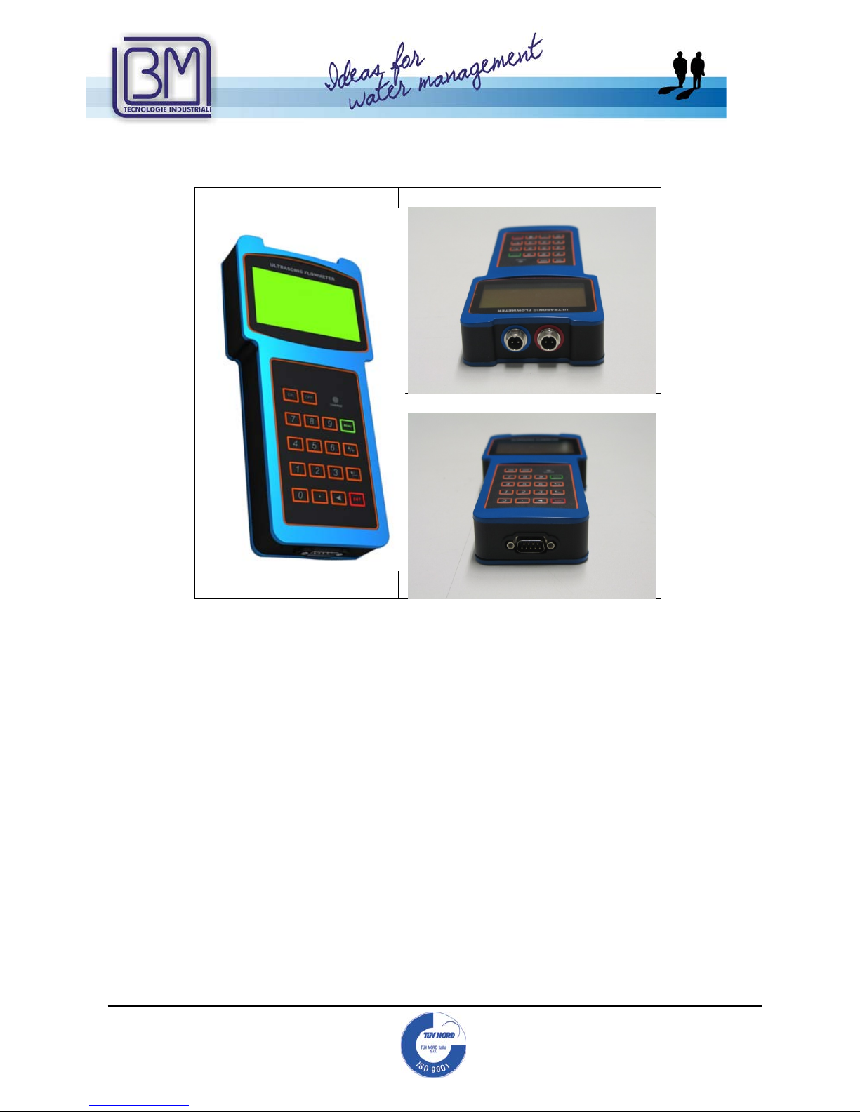
1.2 DESCRIPTION
Frontal View
Top View
Bottom View
1.3 PACKING LIST
• Portable ultrasonic tran sit ti me flow me te r 1 pc
• Serial cable DB9.F 1 pc
• Battery charger 12 VDC/ 0.5 A 1 pc
• Adaptor for serial connector/ battery charger 1 pc
•
Clamp-on sensors TS2 (small)* 2 pcs
•
Clamp-on sensors TM1 (medium) * 2 pcs
•
Clamp-on sensors TL1 (large) * 2 pcs
• Spiral cable, 5mt (optional 10 mt straight cable) 2 pcs
• Acoustic couplant (grease) 1 pc
• Sensors mounting kit 2 pcs
• EC certification 1 pc
• Instruction Manual 1 pc
* depending from the type of sensors ordered by the customer

Mod.BM43
COM
Vers.1.0
16/11/2005
Page 9 of
95
B.M. Tecnologie Industriali
Via Praimbole 13
35010 LIMENA (PD)
VAT No. IT02459940280
Tel. +39 (0) 49 884.16.51
Fax +39 (0) 49 884.16.54
E-Mail bm@bmtecnologie.it
Web www.bmtecnologie.it
1.4 INTEGRATED REAL TIME CLO CK (RTC)
The user’s setting s are saved into t h e device’s memory for at least 2100 years in case of
power failures. The device could be protected by a PASSWORD.
The RTC remains active until the batt ery discharge tension is 1.5 V.
Ref. to menu M60 for resetting current d ate and time in the format: yy, mm, dd.
1.5 PRODUCT ID
Each device has a serial number, g enerated during its production. It could not be changed,
it should be used in case of repair and it could be displayed by menu M61.
1.6 TECHNICAL FEATURES
FEATURE
SPECIFICATION
Linearity
0.5%
Repeatability
0.2%
Accuracy
+/- 1% of the reading value > = 0.2 m/s
Response time
From 0 to 999 seconds , set by the user.
Speed
+/- 32 m/s
Pipes diameter
From DN20 to DN 6000
Eng. Units
Meters, Feet, Cub i c meters, Cubic feet, USA
Gallons, Imperial Gallons, USA Million
Gallons, set by the user.
Totalizers
7 digit for positive, negative and net
flowrate.
Measurable liquids All the liquids (virtually)
Safety Possible to set a password for blocking the
device.
Display
Graphic dislya4 lines, 16 characters.
Interface
RS232-C from 75 to 57 600 BPS.
Transducers
TS-2, TM-1, TL-1, or High temperature
sensors, at customers request.
Cable lengths From 2 x 5 m up to 2 x 500 m
Supply 3 x AAA Ni-MH batteries (included) for up
to 10 hours of continuous operation
Data logger
Internal data lo gger to save up to 2000
lines of data.
Manual totalizer 7 digit totalizaer for manual a cquisitions
and calibrations.
Housing material
ABS
Housing dimensions
460 (L) x 400 (W) x 110 (H) mm
Total weight
4.5 kg batteries included
Mod.BM43
COM
Vers.1.0
16/11/2005
Page 10 of
95
B.M. Tecnologie Industriali
Via Praimbole 13
35010 LIMENA (PD)
VAT No. IT02459940280
Tel. +39 (0) 49 884.16.51
Fax +39 (0) 49 884.16.54
E-Mail bm@bmtecnologie.it
Web www.bmtecnologie.it
2. INSTALLATION AND OPERATION
The installation of TTFM-100-B-HH-NG series is quite simple. It is only necessary t o
determine the mounting point in the pipe and knowing some information about the pipe’s
dimension.
2.1 MEASURING POINT
It is very important to select the right measuring point. The fluid has to be a measurable
fluid and the pipe should be suitable for this measuring technology.
Do not hesitate to contact B.M. TECNOLOGIE INDUSTRIALI for any further clarification.
Please proceed as f ollows:
1) Select the measuring point on the pip e, in order to have a fluid free from
turbulences.
2) The distance of measurement point upstream is 10D, downstream is within 5D. If
there is valve upstream, it is suggested to increase the distance up to 30 D.
3) Actually, the device could be installed into pipes with lining, but it is suggested to
avoid it above all if the pipe is old or damaged. Pipes should be suitable to this
measuring technology in order to improve measure and precision.
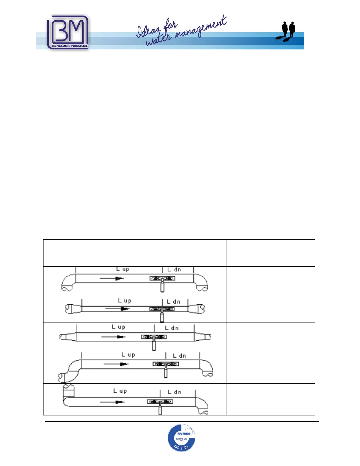
Possibile pipes configuration & possibile transducers position
Upstream
Dimensions
Downstream
Dimensions
L up x
Diameters
L dn x
Diameters
10D 5D
10D 5D
10D 5D
12D 5D
20D 5D

Mod.BM43
COM
Vers.1.0
16/11/2005
Page 11 of
95
B.M. Tecnologie Industriali
Via Praimbole 13
35010 LIMENA (PD)
VAT No. IT02459940280
Tel. +39 (0) 49 884.16.51
Fax +39 (0) 49 884.16.54
E-Mail bm@bmtecnologie.it
Web www.bmtecnologie.it
20D 5D
30D 5D
2.2 REQUIRED CONDITIONS
The more precise the below mentioned inform ation, the better accuracy and measure:
1) Pipe’s external diameter, without liner, if there is a liner.
2) Pipe’s internal diameter or thickness.
3) Pipe’s material or speed of sound through that material.
4) Internal liner: material and thickness or speed of sound through that material.
5) Fluid type or speed of sound through that fluid.
6) Transducers type.
7) Transducers mounting method (V, Z, N, W method).
In M25 menu it is possible to see the right mounting distance between the transducers.

Mod.BM43
COM
Vers.1.0
16/11/2005
Page 12 of
95
B.M. Tecnologie Industriali
Via Praimbole 13
35010 LIMENA (PD)
VAT No. IT02459940280
Tel. +39 (0) 49 884.16.51
Fax +39 (0) 49 884.16.54
E-Mail bm@bmtecnologie.it
Web www.bmtecnologie.it
2.3 A PRACTICAL EXAMPLE OF RA PID SETTINGS
The following example shows an appli c ation with a DN 400 carbon steel pipe, no liner, with
“V” mounted sensors.
IMPORTANT NOTICE:
WHEN THE SET-UP IS COMPLETED, THE USER MUST GO BACK TO M EN U 26 AND
SELECT OPTION 1. SOLIDIFY SETTIN GS, AND THEN PRESS ENTER.
IN THIS WAY THE PARAMETERS WILL BE SAVED EVEN IF THE POWER SUPPLY
GOES OFF.
2.3.1 Fluid & pipe’s features
This is a zinc pipe, so its thickness is not a problem. It is also important to measure the
pipe’s circumference: it should b e 1286 mm. The pipe is PN10 and it will measure potable
water.
2.3.2
Data Entry
ATTENTION! The XXXXX values in the following windows are only examples.
The value could vary and must not be taken as representative.
Switch on the device and it will displ ay:
Ver.
XX.XX
S/N=XXXXXXXX
Then it will display, (it depends from the last switch off) for example:
Flow 0.0000 m3/h *I
No Signal Detected
The transducers are not installed and their mounting distance will be displayed only after
the set-up. Actually the device detect s no signals.
Press and the device will display:
Flow 0.0000 m3/h
*I
Window No. =
MENU

Mod.BM43
COM
Vers.1.0
16/11/2005
Page 13 of
95
B.M. Tecnologie Industriali
Via Praimbole 13
35010 LIMENA (PD)
VAT No. IT02459940280
Tel. +39 (0) 49 884.16.51
Fax +39 (0) 49 884.16.54
E-Mail bm@bmtecnologie.it
Web www.bmtecnologie.it
Press and the device will display window no. 10.
Pipe Outer Perimeter
XXXX mm
Press and :
Pipe Outer Perimeter
1286 mm
If you press a wrong digit, press to correct.
Press and the device will display:
Pipe Outer Diameter
XXX.XXX mm
Press and the device will display:
Pipe Wall Thickness
X.X mm
Press , , + and the it will display:
Pipe Wall Thickness
6.5 mm
Press and the device will display:
Pipe Inner Diameter
396.347 mm
The device calculates the value based on the entered setti n gs.
It is possible to press again and the device will display the paramet ers it
calculated until now.
1
0
1
2
8
6
ENT
6
.
5
ENT

Mod.BM43
COM
Vers.1.0
16/11/2005
Page 14 of
95
B.M. Tecnologie Industriali
Via Praimbole 13
35010 LIMENA (PD)
VAT No. IT02459940280
Tel. +39 (0) 49 884.16.51
Fax +39 (0) 49 884.16.54
E-Mail bm@bmtecnologie.it
Web www.bmtecnologie.it
Press and the device will display:
Pipe Material
[14
1. Stainless
Steel
The pipe material depends from the material of the pipe.
Press and “1” and is blinking.
Pipe Material [14
>1. Stainless Steel
Select the right material by using the
Pipe Material [14
>0. Carbon Steel
Press ENT and and the device will display:
Liner Material [16
0. None, No Liner
In this case, the pipe has no internal lini ng, so “0” is correct.
Press and the device will display:
Fluid Type [20
0. Water (General)
Press and the device will display:
Transducer Type [23
16. Clamp- on TM1
NOTE:
The standard sensors are Clamp-on TM1 type, for pip es fr om DN50 u p to
DN1000.
It is possible to ask for different sensors, depending from the application.
ENT

Mod.BM43
COM
Vers.1.0
16/11/2005
Page 15 of
95
B.M. Tecnologie Industriali
Via Praimbole 13
35010 LIMENA (PD)
VAT No. IT02459940280
Tel. +39 (0) 49 884.16.51
Fax +39 (0) 49 884.16.54
E-Mail bm@bmtecnologie.it
Web www.bmtecnologie.it
Press and the device will display:
Transducer Mounting
0. V
Press and the device will display:
Transducer Spacing
385.268 mm
The displayed value id the sensors mounting distance, as shown in par. 2.2.
It is possible to install the transducers, as shown in the following par. 2.4.
Press and the device will display:
Default settings [26
1. Solidify settings
Press and the device will display:
Save / Load parameters
>>
Press to go through the parameters:
Save / Load parameters
>> To Browse
Or set up one of the 9 (0…8) preset configurations:
Save / Load parameters
>> Entry to LOAD
Press and the device will display:
Save / Load parameters
>> Entry to SAVE

Mod.BM43
COM
Vers.1.0
16/11/2005
Page 16 of
95
B.M. Tecnologie Industriali
Via Praimbole 13
35010 LIMENA (PD)
VAT No. IT02459940280
Tel. +39 (0) 49 884.16.51
Fax +39 (0) 49 884.16.54
E-Mail bm@bmtecnologie.it
Web www.bmtecnologie.it
Press and the device will display:
Save / Load parameters
0: 409,347 mm, Carbon
This setting refers to the example configuration: DN400 carbon steel pipe.
Press and the device will display:
Save / Load parameters
Entry to SAVE
Press MENU, 1, ENT and the device will di sp l ay:
Flow 0.0000 m3/h *I
No Signal Detected
Now it is possible to install the transducers.

Mod.BM43
COM
Vers.1.0
16/11/2005
Page 17 of
95
B.M. Tecnologie Industriali
Via Praimbole 13
35010 LIMENA (PD)
VAT No. IT02459940280
Tel. +39 (0) 49 884.16.51
Fax +39 (0) 49 884.16.54
E-Mail bm@bmtecnologie.it
Web www.bmtecnologie.it
2.4 INSTRUCTIONS FOR CLAMP-ON SENSORS INSTALLATION
If you ordered Clamp-on sensors type TTS100-TS2-NG, TTS100-M1-NG,
TTS100-L1-NG, TTS100-S1-NG-HT, TTS100-M1-NG-HT the following instructions are
very important for a correct installation of the sensors:
I. In order to install the sensors, check if the pipe has features which could affect the
measure, i.e. rust, dirt…
II. Measure the pipes’ diameter by using a callipers

Mod.BM43
COM
Vers.1.0
16/11/2005
Page 18 of
95
B.M. Tecnologie Industriali
Via Praimbole 13
35010 LIMENA (PD)
VAT No. IT02459940280
Tel. +39 (0) 49 884.16.51
Fax +39 (0) 49 884.16.54
E-Mail bm@bmtecnologie.it
Web www.bmtecnologie.it
Or, if it is not possi ble to measure the diameter, please measure the pipe’s
circumference:
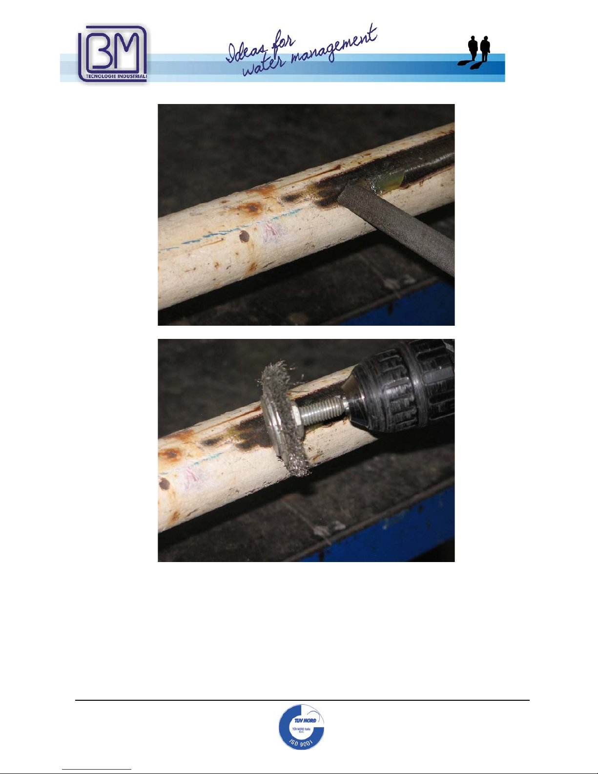
III. Clean the area where the sensors will be installed by using one of the following
tools:
Or
Mod.BM43
COM
Vers.1.0
16/11/2005
Page 19 of
95
B.M. Tecnologie Industriali
Via Praimbole 13
35010 LIMENA (PD)
VAT No. IT02459940280
Tel. +39 (0) 49 884.16.51
Fax +39 (0) 49 884.16.54
E-Mail bm@bmtecnologie.it
Web www.bmtecnologie.it
Or

Mod.BM43
COM
Vers.1.0
16/11/2005
Page 20 of
95
B.M. Tecnologie Industriali
Via Praimbole 13
35010 LIMENA (PD)
VAT No. IT02459940280
Tel. +39 (0) 49 884.16.51
Fax +39 (0) 49 884.16.54
E-Mail bm@bmtecnologie.it
Web www.bmtecnologie.it
IV. The pipe section where the sensors will be installed should be completely clean:
V. Measure the pipe’s thickness.
This could be done by using our Thickness Gauge TT100-TM8812-NG

Mod.BM43
COM
Vers.1.0
16/11/2005
Page 21 of
95
B.M. Tecnologie Industriali
Via Praimbole 13
35010 LIMENA (PD)
VAT No. IT02459940280
Tel. +39 (0) 49 884.16.51
Fax +39 (0) 49 884.16.54
E-Mail bm@bmtecnologie.it
Web www.bmtecnologie.it
Before placing and using the Thickness Gauge sensors, remember to use the
coupling grease:
Otherwise, the sensors could loo se the grip to the pipe.
VI. Enter the following values into device’s menus:
- pipe’s diameter (MENU 11) or pipe’ s circumference (MENU 10)
- pipe’s thickness (MENU 12)
- type of sensors to be used (MENU 23)
- Sensors mounting method (MENU 24)
The device will display the distance at which the sensors should be installed
(MENU 25).
Now it is possible to start the sensors install at i on.
Please remember to u se the coupling grease:
Otherwise, the sensor could loose grip to the pipe.

Mod.BM43
COM
Vers.1.0
16/11/2005
Page 22 of
95
B.M. Tecnologie Industriali
Via Praimbole 13
35010 LIMENA (PD)
VAT No. IT02459940280
Tel. +39 (0) 49 884.16.51
Fax +39 (0) 49 884.16.54
E-Mail bm@bmtecnologie.it
Web www.bmtecnologie.it
VII. Sensors could be installed by using a fixing bra c ket:
Or by using our Rail Guide Mounting System RGMS-TS2-TM1-NG-FIX
(only with TS2 & TM1 sensors, pipes form DN15 to DN300).

Mod.BM43
COM
Vers.1.0
16/11/2005
Page 23 of
95
B.M. Tecnologie Industriali
Via Praimbole 13
35010 LIMENA (PD)
VAT No. IT02459940280
Tel. +39 (0) 49 884.16.51
Fax +39 (0) 49 884.16.54
E-Mail bm@bmtecnologie.it
Web www.bmtecnologie.it
VIII. Install the sensors according to the distance value the device displays in
MENU 25:
a) Installation of the clamp-on sensors wi th the fixing brackets:
Installation is completed:

Mod.BM43
COM
Vers.1.0
16/11/2005
Page 24 of
95
B.M. Tecnologie Industriali
Via Praimbole 13
35010 LIMENA (PD)
VAT No. IT02459940280
Tel. +39 (0) 49 884.16.51
Fax +39 (0) 49 884.16.54
E-Mail bm@bmtecnologie.it
Web www.bmtecnologie.it
b) Installation of the clamp-on sensors with our Rail Guide Mounting System
RGMS-TS2-TM1-NG-FIX (only with TS2 & TM1 sensors, pipes form DN15 t o DN300).
Installation is completed:

Mod.BM43
COM
Vers.1.0
16/11/2005
Page 25 of
95
B.M. Tecnologie Industriali
Via Praimbole 13
35010 LIMENA (PD)
VAT No. IT02459940280
Tel. +39 (0) 49 884.16.51
Fax +39 (0) 49 884.16.54
E-Mail bm@bmtecnologie.it
Web www.bmtecnologie.it
2.5 TRANSDUCER MOUNTING METHODS
The transducers mounting posit ions are related to the pipe diameter and to the type of
sensors. V and Z methods are the most common. By the way, V mounting is suggested.
The other mounting methods are N and W.
The letters V, Z, N, W stands for the number of signal crossings from one transducer to
another.
• Z= one crossing. Suitable for pipes > DN250 mm or smaller.
• V= two crossings. It is the easiest mounting method for DN600-800 pipes with TL-1
or TM-1 transducers.
• N= three crossings. Suitable for small pipes, DN100 or smaller, with TS-2
transducers. It similar to “Z” method, but for small pipes. In this case, the mounting
distance will be bigger.
• W= four crossings. Suitable for DN20 pipes with TS-2 transducers. It similar to “V”
method, but for small pipes. In this c ase, the mounting distance will be bigg er.
The following example shows the different m ounting solutions.
“Z” mounting method
“V” mounting method
“N” mounting method

Mod.BM43
COM
Vers.1.0
16/11/2005
Page 26 of
95
B.M. Tecnologie Industriali
Via Praimbole 13
35010 LIMENA (PD)
VAT No. IT02459940280
Tel. +39 (0) 49 884.16.51
Fax +39 (0) 49 884.16.54
E-Mail bm@bmtecnologie.it
Web www.bmtecnologie.it
“W” mounting method
“W” mounting method
V mounting method is the most commo n. It can be applied to almost all the applications: it
is the most simple and rapid one.
Z mounting method is suggested only if the signal strength, UP and DOWN (DN) is smaller
than 60 and Q valu e i s smaller than 60, see MENU “90”.

Mod.BM43
COM
Vers.1.0
16/11/2005
Page 27 of
95
B.M. Tecnologie Industriali
Via Praimbole 13
35010 LIMENA (PD)
VAT No. IT02459940280
Tel. +39 (0) 49 884.16.51
Fax +39 (0) 49 884.16.54
E-Mail bm@bmtecnologie.it
Web www.bmtecnologie.it
Strenth+Quality
[90
UP:54.4 DN:56.5
Q=45
2.5.1 “V” mounting method
The “V” method uses a bounce into the pipe and the ultrasonic wave goes through
more distance. The measuring principle is based on the difference of time and thro ugh
a “V” distance, the time needed is bigger a nd the precision higher. In case of ho r izontal
mounting, it is suggested to avoid m ounting the sensors on the top or on the bottom of
the pipe. Air bubbles on the top could stop the ultrasonic wave and the dump on the
bottom decrease and change the ultraso ni c entra nce angle. Refer to the picture below.
In case of vertical mounting, a void installing
the transducers on downward pipe walls,
even if they are under pressure. The pipes
with an external liner such as tar,
polyethylene, epoxy, should be cleaned
when in contact with the transducers.
A tube for acoustic coupling gel for sensor s
installation, is included in the supply. Use a
small quantity of coupling grease in or der to
improve acoustic the contact between the
sensor and the pip e’s external surface.

Mod.BM43
COM
Vers.1.0
16/11/2005
Page 28 of
95
B.M. Tecnologie Industriali
Via Praimbole 13
35010 LIMENA (PD)
VAT No. IT02459940280
Tel. +39 (0) 49 884.16.51
Fax +39 (0) 49 884.16.54
E-Mail bm@bmtecnologie.it
Web www.bmtecnologie.it
2.5. 2 “Z ” mounting method
Press 1 while in menu 24 , if you want to choose “Z” mounting.
M24
Transducer Mounting
0. V-Method
=> 1. Z-Method
Press and the device will display:
M25
Transducer Spacing
152.771 mm
“Z” mounting method is more compli c ated than “V” mounting method: it is necessary to
create a band of foil as long as the pipe cir c um ferenc e and as wide as indicated i n MENU
25. Additionally, add a piece of paper to wrap the pipe.
Please refer to the picture below for finding the two lines needed to trace the exact half
point of the pipe.

Mod.BM43
COM
Vers.1.0
16/11/2005
Page 29 of
95
B.M. Tecnologie Industriali
Via Praimbole 13
35010 LIMENA (PD)
VAT No. IT02459940280
Tel. +39 (0) 49 884.16.51
Fax +39 (0) 49 884.16.54
E-Mail bm@bmtecnologie.it
Web www.bmtecnologie.it
Once the fascia is fixed on the pipe’s c i r c um ferenc e (with adhesive tape), it is possib le to
fix the sensors, as shown in the picture. If the pipe is horizontally mounted, it is suggested
to mount the sensors as shown in the next pictur e. If the pipe is vertically mounted, refer
to the instructions of “V” mounting metho d.
2.5.3 “W” & “N” Mounting Methods
These methods are suitable for small pipes, DN100 or less, wi th TS-2 transducers.
The signal path consists of four cro ssing s (for “W” method) and three crossings (for “ N”
method) inside t h e pipe. These methods are used to increase the transit time a n d
receiving time, otherwise the signal path in small pipes will be too short.
In “W” method, t h e sen sors are placed on the same side of the pipe at a definite distance,
in “N” method; they are placed on the opposite sides of the pipe, at a definite distance.
These methods are not very used because sm all sensors TS-2 could b e installed by using
“Z” method.
To choose “N” method, press 2 while in menu 24.
M24
Transducer Mounting
0. V-Method
1. Z -Method
=>2. N- Method

Mod.BM43
COM
Vers.1.0
16/11/2005
Page 30 of
95
B.M. Tecnologie Industriali
Via Praimbole 13
35010 LIMENA (PD)
VAT No. IT02459940280
Tel. +39 (0) 49 884.16.51
Fax +39 (0) 49 884.16.54
E-Mail bm@bmtecnologie.it
Web www.bmtecnologie.it
Press and the device will display:
M25
Transducer Spacing
XXXXX mm
To choose “W” method, press 3 while in menu 24.
M24
Transducer Mounting
0. V-Method
1. Z -Method
2. N-Method
=> 3. W-Method
Press and the device will display:
M25
Transducer Spacing
XXXXX mm
Press and the device will display:
Save Paremeters [26
Select a room
by ENT UP DN
Save the configuration in one of the 18 rooms available (from 0 to 17) and press
Default Setting [26
>1. Solidify Setting
ENT

Mod.BM43
COM
Vers.1.0
16/11/2005
Page 31 of
95
B.M. Tecnologie Industriali
Via Praimbole 13
35010 LIMENA (PD)
VAT No. IT02459940280
Tel. +39 (0) 49 884.16.51
Fax +39 (0) 49 884.16.54
E-Mail bm@bmtecnologie.it
Web www.bmtecnologie.it
2.5.4
Mounting Analysis
After checking the strength of the received signal, the total spreading time, the time
difference and the rate of spreadi ng time, it is possible to confirm if the installation is
correct.
2.5.5
Signal s treng th and qual ity M90
Digit
The strength of signals is displayed by numbers from 00.0 to 99.9.
00.0 means no signal received, 99.9 means ma x sig nal. In normal working conditions, the
signal strength should be higher than 60.0.
The signal quality (Q) is displayed by numbers from 00.0 to 99.9. 00.0 m eans the signal is
the worst. 99.9 mean signal is the best. In normal working conditions, the signal quality
should be higher than 60.0.
During installation, please pay attention to signal strength and quality: they should be at
the maximum level.
M90 0.0000%
Strenth+Quality
S=000, 000 Q=00
Detect No Signal

Mod.BM43
COM
Vers.1.0
16/11/2005
Page 32 of
95
B.M. Tecnologie Industriali
Via Praimbole 13
35010 LIMENA (PD)
VAT No. IT02459940280
Tel. +39 (0) 49 884.16.51
Fax +39 (0) 49 884.16.54
E-Mail bm@bmtecnologie.it
Web www.bmtecnologie.it
2.5.6 To ta l spreading time, time difference M93
Digit
Total Time,Delta
Time
623,80uS, 242,12nS
The measurement method is based o n ti me difference, so the time and other disp layed
values can identify a correct install at i on. In normal operating conditions, t he time
difference should be smaller that ten p erc ent (10%). If the pipe diameter is small or the
speed is too low, the difference may be a l itt le higher. If the difference (and also flow and
speed) is too high, it means the signal quality is very bad. The reason may be: pipe’s
features, wrong installation o r wrong parameters setting.
2.5.7
Relation between calculated and measured transit time
To know if the sensors are well mounted, you should calcolate:
TIME – RATE = TOM * 100
TOS
In normal working conditions it should be 100 +/- 3%.
Digit
TOM/TOS*100
xxx,xx %
And eventually confirm the right mo unting method.
MENU
9
3

Mod.BM43
COM
Vers.1.0
16/11/2005
Page 33 of
95
B.M. Tecnologie Industriali
Via Praimbole 13
35010 LIMENA (PD)
VAT No. IT02459940280
Tel. +39 (0) 49 884.16.51
Fax +39 (0) 49 884.16.54
E-Mail bm@bmtecnologie.it
Web www.bmtecnologie.it
3. DISPLAY WINDOWS
This chapter will explain all the display wi ndows of TTFM100 Series and their contents.
The user can enter this menu by pressing
[*][*] represent the number of the window to be displayed .
The following list includes all the available windows.
3.1 FLOW RATE- TOTALIZERS MENU
00 All Totalizers
01 Main Display P OS Totalizer
02 Main Disp lay NEG Totalize r
03 Main Disp lay NET Totalizer
04 Date Time / Flow Rate + signal
05 Date Time / Signal Velocity
06 Received Shape of Signal
07 Battery Voltage / Battery remaining working time
08 System Error Code + Signal
0 9 Net Flow Today + Veloci ty
3.2 INITIAL SETTING MENU
10 Pipe Outer Perimeter
11 Pipe Outer Diameter
12 Pipe Wall Thickness
13 Pipe Inner Diameter
14 Pipe Material
(15 Pipe Sound Velocity)
if in menu 14 the user chose “other”
16 Liner Mate rial
(18 Liner Thickn ess)
if in menu 16 the user chose “other”
19 Inside ABS Thickness
20 Fluid Type
(21 Fluid Sound Velocity)
if in menu 20 the user chose “other”
(22 Fluid Viscosity)
if in menu 20 the user chose “other”
23 Trans ducer Ty pe
24 Transducer M ounting
25 Transducer Spacing

Mod.BM43
COM
Vers.1.0
16/11/2005
Page 34 of
95
B.M. Tecnologie Industriali
Via Praimbole 13
35010 LIMENA (PD)
VAT No. IT02459940280
Tel. +39 (0) 49 884.16.51
Fax +39 (0) 49 884.16.54
E-Mail bm@bmtecnologie.it
Web www.bmtecnologie.it
26 Save Parameters
27 Load Parameters
28 Poor Signal
29 Empty Pipe Set up
3.3 FLOW RATE UNITS MENU
30 Measurement Unit
31 Flow Rate Units
32 Totalize Units
33 Totalize Multiplier
34 NET Totalizer
35 POS Totalizer
36 NEG Totalizer
37 Totalizer Reset
38 Manual Totalizer
39 Language Selection
3.4 OPTIONAL SETTING MENU
40 Damping
41 Low Cutoff Value
42 Set Zero
43 Reset Zero
44 Manual Zero Point
45 Scale Factor
46 Network IDN
47 System Lock
(48 Keypad Lock Code)
if in the menu 47 the user chose YES
49 Communication Tester
3.5 INPUTS/ OUTPUTS MENU
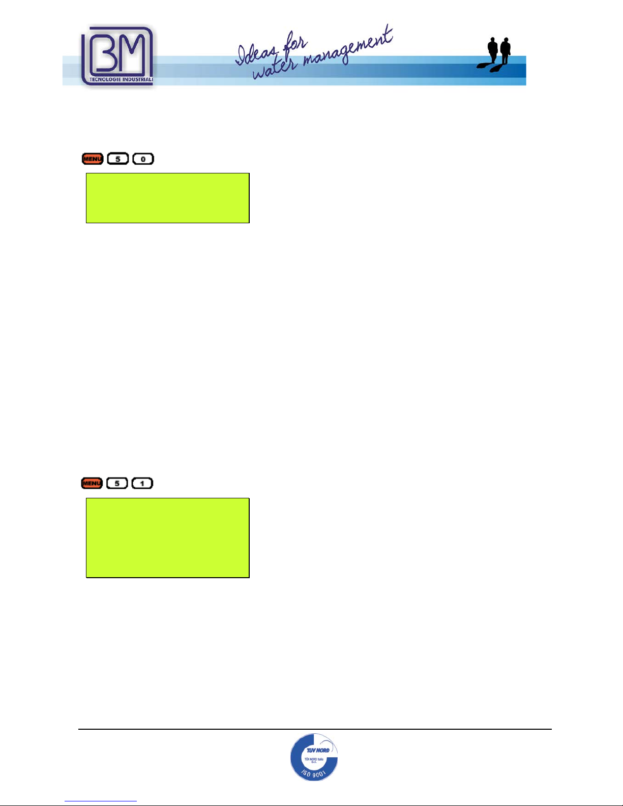
50 Logger Option
51 Logger Setup
52 Data Direction
53 Buffer Viewer
54 AI5 Value Range
60 Date and Time
61 Software Version and Serial Number (ESN)
62 RS-232C Setup
67 FO Frequency Range

Mod.BM43
COM
Vers.1.0
16/11/2005
Page 35 of
95
B.M. Tecnologie Industriali
Via Praimbole 13
35010 LIMENA (PD)
VAT No. IT02459940280
Tel. +39 (0) 49 884.16.51
Fax +39 (0) 49 884.16.54
E-Mail bm@bmtecnologie.it
Web www.bmtecnologie.it
68 Low FO Flow Rate
69 High FO Flow Rate
70 LCD Backlight Option
71 LCD Contrast
72 Working Timer
73 Alarm #1 Low Value
74 Alarm #1 High Value
75 Alarm #2 Low Value
76 Alarm #2 High Value
77 Buzzer Setup
78 OCT Output Setup
82 Date Totalizer
85 Auto Power Off
86 Auto Control Enabled
87 Power selection
88 RCV Window start
89 RCV Window end
3.6 DIAGNOSTICS MENU
90 Single Strength and Quality
91 TOM / TOS*100
92 Fluid Sound Velocity
93 Total Time and Delta Time
94 Reynolds Numbe r and Factor
3.7 OTHER DISPLAYS MENU
From menu 94 onwards, by pressing
It is possible to display some additional information
M+ 0 Power ON/OFF Time
M+ 1 Total Working Time
M+ 2 Last Power Off
M+ 3 Last Flow Rate
M+ 4 ON/OFF Times
M+ 5 Calculator
M+ 6 Velocity change
M+ 7 Protocol Select
M+ 8 Receive Shape

Mod.BM43
COM
Vers.1.0
16/11/2005
Page 36 of
95
B.M. Tecnologie Industriali
Via Praimbole 13
35010 LIMENA (PD)
VAT No. IT02459940280
Tel. +39 (0) 49 884.16.51
Fax +39 (0) 49 884.16.54
E-Mail bm@bmtecnologie.it
Web www.bmtecnologie.it
3.8 FLOW RATE- TOTALIZERS MENU ANALYSIS
Digit
and the device will display
POS +4879 m3
NEG -336 m3
NET +4543 m3
S=000, 000 Q=00
I
This a display window. The measuring units should be set up in menu M31 a nd M32.
NET is the net totalizer, result of adding the positive totalizer POS to the negative totalizer
NEG.
Digit
and the device will display
POS +4879 m3
Flow 123.00 l/s
Vel 0.5678 m/s
S=679, 681 Q=56R
This a display window. The measuring units should be set up in menu M31 and M32.
Digit
and the device will display
NEG -336 m3
Flow 123.00 l/s
Vel 0.5678 m/s
S=679, 681 Q=56R
This a display window. The measuring units should be set up in menu M3. The POS value
refers to the positive totalizer.
Digit
and the device will display
NET +4543 m3
Flow 123.00 l/s
Vel 0.5678 m/s
S=679, 681 Q=56R
This a display window. The measuring units should be set up in menu M31 a nd M36. The
NEG value refers to the negative totalizer.

Mod.BM43
COM
Vers.1.0
16/11/2005
Page 37 of
95
B.M. Tecnologie Industriali
Via Praimbole 13
35010 LIMENA (PD)
VAT No. IT02459940280
Tel. +39 (0) 49 884.16.51
Fax +39 (0) 49 884.16.54
E-Mail bm@bmtecnologie.it
Web www.bmtecnologie.it
Digit
and the device will display
Date 06-11-12
Time 09:54:00
Flow 123.00 l/s
S=679, 681 Q=56R
This window displays date and tim e in the following format yy-mm-dd; hh-mm-ss, and the
current flow rate.
Date and time should be set up in m enu M 60.
Digit
and the device will display
Date 06-11-12
Time 09:54:00
Vel 0.5678 m/s
S=679, 681 Q=56R
This window displays date and tim e in the following format yy-mm-dd; hh-mm-ss, and the
current speed.
Date and time should be set up in menu M60.
Digit
and the device will display
RCV
SHP___________
This window displays shape of the signal received by the transducers
Digit
and the device will display
Battery Voltage
3.5679 V
Battery Worktime
00:45:34
This window displays the battery features and status.

Mod.BM43
COM
Vers.1.0
16/11/2005
Page 38 of
95
B.M. Tecnologie Industriali
Via Praimbole 13
35010 LIMENA (PD)
VAT No. IT02459940280
Tel. +39 (0) 49 884.16.51
Fax +39 (0) 49 884.16.54
E-Mail bm@bmtecnologie.it
Web www.bmtecnologie.it
Digit
and the device will display
Error Code
-----------------------R
System Normal
S=679, 681 Q=56R
This window displays the error codes. Please refer to the list of complete error codes at
page 65.
Digit
and the device will display
Net Flow Today
134 m3
Vel 0.5678 m/s
S=679, 681 Q=56R
This window displays the net daily flow rate.

Mod.BM43
COM
Vers.1.0
16/11/2005
Page 39 of
95
B.M. Tecnologie Industriali
Via Praimbole 13
35010 LIMENA (PD)
VAT No. IT02459940280
Tel. +39 (0) 49 884.16.51
Fax +39 (0) 49 884.16.54
E-Mail bm@bmtecnologie.it
Web www.bmtecnologie.it
3.9 INITIAL SETTING MENU ANALYSIS
Digit
and the device will display
M10
Outer Perimeter
1286 mm
This window is used to set up the p i pe’s perimeter, if known or measurable.
Digit
and the device will display
M11
Outer Diameter
409.347 mm
This window is used to set up the external pipe’s diameter. When the pipe’s external
perimeter diameter is set up, the exter n al pip’s diameter is automatically setup too.
Digit
and the device will display
M12
Wall Thickness
6.5 mm
This window is used to set up the p i pe’s thickness. It is also possible to pass over this
menu and go to the menu M13, used to set up the internal pipe’s diameter.
Digit
and the device will display
M13
Inner Diameter
396,347 mm
This window is used to set up the net pipe’s internal diameter.
Digit
and the device will display
M14
Pipe Material
0.Carbon Steel
This window is used to set up the pipe’s material.
Press ENTER to activate the material selection.
Use the arrow keys to scroll among the list:

Mod.BM43
COM
Vers.1.0
16/11/2005
Page 40 of
95
B.M. Tecnologie Industriali
Via Praimbole 13
35010 LIMENA (PD)
VAT No. IT02459940280
Tel. +39 (0) 49 884.16.51
Fax +39 (0) 49 884.16.54
E-Mail bm@bmtecnologie.it
Web www.bmtecnologie.it
0 Carbon Steel
1 Stainless Steel
2 Cast Iron
3 Ductile Iron
4 Copper
5 PVC
6 Aluminium
7 Asbestos
8 Fibreglass
9 Other*
*If option 9 is chosen, the sound speed set up is mandatory, see the APPENDIX,
from page 70.
This window will de displayed only i f i n M14 the user chose “9. OTHER”
Digit
and the device will display
M15
Pipe Sound Vel
xxxx m/s
Set up the speed of sound through the pipe material, referring to the construction material
of the pipe.
For information about the sound speed through other types of materials that
are not included in the list, please refer to the tables starting at page 70.
Digit
and the device will display
M16
Liner Material
0.No Liner
This window is used to set up the liner’ s m aterial.
Press ENTER to activate the material selection.
Use the arrow keys to scroll among the list :
0 NO Liner
1 Tar Epoxy
2 Rubber
3 Mortar
4 Polypropylene
5 Polystyrol

Mod.BM43
COM
Vers.1.0
16/11/2005
Page 41 of
95
B.M. Tecnologie Industriali
Via Praimbole 13
35010 LIMENA (PD)
VAT No. IT02459940280
Tel. +39 (0) 49 884.16.51
Fax +39 (0) 49 884.16.54
E-Mail bm@bmtecnologie.it
Web www.bmtecnologie.it
6 Polystryene
7 Polyester
8 Polyethylene
9 Ebonite
10 Teflon
11 Other*
*If option 11 is chosen, the sound speed s et up is mandatory, see the
APPENDIX, f rom page 70.
This Menu will activate only if in M16 the user chose “11. OTHER”
Digit
and the device will display
M17
Liner Sound Velocity
xxxx m/s
Set up the spreading time of sound through the constructi on material of the liner.
For information about the sound speed through other types of materials that
are not included in the list, please refer to the tables starting at page 70.
This Menu will activate only if in M16 the user chose “11. OTHER”
Digit
and the device will display
M18
Liner Thickness
0 mm
Set up the internal liner thickness.
Digit
and the device will display
Inside ABS Thickness
[18
0
mm
This menu is not used, please ignore it.
MENU
1
9

Mod.BM43
COM
Vers.1.0
16/11/2005
Page 42 of
95
B.M. Tecnologie Industriali
Via Praimbole 13
35010 LIMENA (PD)
VAT No. IT02459940280
Tel. +39 (0) 49 884.16.51
Fax +39 (0) 49 884.16.54
E-Mail bm@bmtecnologie.it
Web www.bmtecnologie.it
Digit
and the device will display
M20
Fluid Type
0 Water
This window is used to set up the measuring flow type.
Press ENT to enable the fluid selection and use the arrow keys to scroll the list:
0 Water
1 Sea Water
2 Kerosene
3 Gasoline
4 Fuel Oil
5 Crude Oil
6 Propane (-45°C)
7 Butane (0°C)
8 Other
9 Diesel Oil
10 Castor Oil
11 Peanut Oil
12 Gasoline #90
13 Gasoline #93
14 Alcohol
15 Water (+125°C)
Press ENT to confirm.
This Menu will activate only if in M20 the user chose “8. OTHER”
Digit
and the device will display
M21
Fluid Sound Velocity
1482.8 m/s
Enter speed of sound through the fluid to be measured.
For information about the sound speed through other types of materials that
are not included in the list, please refer to the tables starting at page 70.

Mod.BM43
COM
Vers.1.0
16/11/2005
Page 43 of
95
B.M. Tecnologie Industriali
Via Praimbole 13
35010 LIMENA (PD)
VAT No. IT02459940280
Tel. +39 (0) 49 884.16.51
Fax +39 (0) 49 884.16.54
E-Mail bm@bmtecnologie.it
Web www.bmtecnologie.it
This menu will activate only if in M20 the user chose “8. OTHER”
Digit
and the device will display
M22
Fluid Viscosity
1.0038 cST
Enter the viscosity of the fluid to be measured.
Digit
and the device will display
Transducer Type
[23
0. Clamp-on TM-1
This window is used to set up the type of transducers.
Press ENT to enable the transducers type selection and use the arrow keys to scroll the
list:
0. Standard M
1. Plug-in type A
2. Clamp-on TM-1 *
3. User Type
4. Standard B
5. Plug-in Type B45
6. Standard L
7. Clamp-on TS-2 *
8. Standard M1
9. Plug-in Type C
10. Standard HS
11. Standard HM
12. Standard S1
13. PI-Pipe
14. Standard L1
15.Clamp-on TL-1 *
* OUR STANDARD CLAMP-ON SENSORS
Press ENT to confirm the type of tra nsducers.
Selection No. 3 “USER TYPE” allows the user to install types of sensors not included in the
list. In this case, it is necessary to enter some more information about the technical
features of the new type of sensors:

Mod.BM43
COM
Vers.1.0
16/11/2005
Page 44 of
95
B.M. Tecnologie Industriali
Via Praimbole 13
35010 LIMENA (PD)
VAT No. IT02459940280
Tel. +39 (0) 49 884.16.51
Fax +39 (0) 49 884.16.54
E-Mail bm@bmtecnologie.it
Web www.bmtecnologie.it
1. wedge degree of u l tr asonic impulse.
Pi-PipeParameter
Wedge Degree
45 deg
2. speed of sound.
Pi-PipeParameter
Wedge Sound Velocity
2720 m/s
3. distance from crystal to sensor wedge.
Pi-PipeParameter
Wedge Distance
32 mm
4. delay of ultrasonic signal.
Pi-PipeParameter
Wedge Time Delay
5.18 uS
Digit
and the device will display
M24
Txducer Mounting
0. V -Method
This window is used to set up the mounting method of the transducers.
Press ENT to enable the transducers type selection and use the arrow keys to scr oll the
list:
0. V Method
1. Z Method
2. N Method (small pipes)
3. W Method (small pipe)
Press ENT to confirm the type of tra nsducers.
Digit
and the device will display
M25
Transducer Spacing
385.268 mm
This window informs about the mo unting distance of the transducers. See. Par. 2.4-2.5.

Mod.BM43
COM
Vers.1.0
16/11/2005
Page 45 of
95
B.M. Tecnologie Industriali
Via Praimbole 13
35010 LIMENA (PD)
VAT No. IT02459940280
Tel. +39 (0) 49 884.16.51
Fax +39 (0) 49 884.16.54
E-Mail bm@bmtecnologie.it
Web www.bmtecnologie.it
Digit
and the device will display
M26
Save Parameters
Select a room
by ENT UP DN
This windows allows the user to save the configuration. It is possible to save up to 18
configurations (from 0 to 17).
Digit
and the device will display
M27
Load Parameters
Select a room
by ENT UP DN
This window is used to upload one of t he 18 saved configurations. Press ENT and t hen use
the arrow keys to scroll among the configurations. Press ENT to select the desired one.
Digit
and the device will display
M28
Holding Poor Signal
YES
This window is used to set up the d evic e in order to maintain the last readi ng as valid in
case of temporary loss of signal. If NO is selected, output signal could be modified.
Digit
and the device will display
M29
Empty Pipe Setup
0
This window is used to set up a m i n threshold. Below that threshold the device considers
the pipe as empty. Set up a value among 30 and 40 in order t o be sure the device does
not measure when the pipe is empty.

Mod.BM43
COM
Vers.1.0
16/11/2005
Page 46 of
95
B.M. Tecnologie Industriali
Via Praimbole 13
35010 LIMENA (PD)
VAT No. IT02459940280
Tel. +39 (0) 49 884.16.51
Fax +39 (0) 49 884.16.54
E-Mail bm@bmtecnologie.it
Web www.bmtecnologie.it
3.10 FLOW RATE UNITS MENU ANALYSIS
Digit
and it will display
M30
Measurement Units
Metric
This window is used to set up the measuring system:
0. metric
1. English
Press ENT and then use the arrow keys to choose the measuring system. Confirm with
ENT.
Digit
and the it will display
M31
Flow Rate Units
m3/h
This window is used to set up the measuring flow rate units. Press ENT and then use the
arrow keys to select the measuring unit am ong:
0. Cubic Meters
1. Litres
2. USA Gallons
3. Imperial Gallons
4. USA Million Gallons
5. Cubic Feet (cf)
6. USA Barrels
7. Imperial Barrels
8. Oil Barrels (ob)
Press ENT to confirm the selection and it will display:
M31
Cubic Meters (m3)
:: /hour
/day
Use the arrow keys to select the time units to w hich the current flow rate should refer:
/hour
/day
/min
/sec

Mod.BM43
COM
Vers.1.0
16/11/2005
Page 47 of
95
B.M. Tecnologie Industriali
Via Praimbole 13
35010 LIMENA (PD)
VAT No. IT02459940280
Tel. +39 (0) 49 884.16.51
Fax +39 (0) 49 884.16.54
E-Mail bm@bmtecnologie.it
Web www.bmtecnologie.it
Press ENT to confirm the selection.
Digit
and the it will display
M32
Totalizer Units
Cubic Meters
This window is used to set up totalizing flow rate units, please refer to menu M 31 f or what
concerns Volumetric units and their setting.
Factory settings are in m3.
Press ENT and then use the arrow keys to select t he measuring unit among:
0. Cubic Meters
1. Litres
2. USA Gallons
3. Imperial Gallons
4. USA Million Gallons
5. Cubic Feet (ct)
6. USA Barrels
7. Imperial Barrels
8. Oil Barrels (ob)
Digit
and the it will display
M33
Totalizer Multiplier
X1
This window is used to set up the multiplying factor for totalization, in order to avoid
reaching the max. counting in a shor t time.
Press ENT and then use the arrow keys to select among:
0. X 0.001 (1E-3)
1. X 0.01
2. X 0.1
3. X1
4. X10
5. X100
6. X1000
7. X10000 (1E+4)
Press ENT to confirm.

Mod.BM43
COM
Vers.1.0
16/11/2005
Page 48 of
95
B.M. Tecnologie Industriali
Via Praimbole 13
35010 LIMENA (PD)
VAT No. IT02459940280
Tel. +39 (0) 49 884.16.51
Fax +39 (0) 49 884.16.54
E-Mail bm@bmtecnologie.it
Web www.bmtecnologie.it
Digit
and the it will display
M34
NET Totalizer
ON
This window is used to enabl e the net totalizer, between positive and negative totalizers.
Factory setting is ON.
Press ENT and then use the arrow keys to select ON or OFF. Press ENT to confirm.
Digit
and the it will display
M35
POS Totalizer
ON
This windows is used to enable the positive totalizer. Factory setting is ON.
Press ENT and then use the arrow keys to select ON or OFF. Press ENT to confirm.
Digit
and the it will display
M36
NEG Totalizer
ON
This windows is used to enable the negative totalizer. Factory setting is ON.
Press ENT and then use the arrow keys to select ON or OFF. Press ENT to confirm.
Digit
and the it will display
M37
Totalizer Reset?
Selection
This window is used to enable the comp lete or selective reset of internal co unters.
Press ENT and then use the arrow keys to select NO or YES. If YES is cho sen , please select
among:
None
All
NET TOtalizer
POS Totalizet
NEG Totalizer

Mod.BM43
COM
Vers.1.0
16/11/2005
Page 49 of
95
B.M. Tecnologie Industriali
Via Praimbole 13
35010 LIMENA (PD)
VAT No. IT02459940280
Tel. +39 (0) 49 884.16.51
Fax +39 (0) 49 884.16.54
E-Mail bm@bmtecnologie.it
Web www.bmtecnologie.it
Press ENT to confirm the selection and the device will display:
M37
Select Totalizer
Reset Finished
Digit
and the it will display
M38
Manual Totalizer
ENT When Ready
This window is used to enable the totalizer backlog. Press ENT to enable the backlog (ON),
press ENT again to disable the backlog (OFF).
Digit
and the it will display
M39
Language
English
This window is used to select the device’s d i splay language.
Press ENT and then use th e arrow keys to select the language. Press ENT to confirm.
Digit
and the it will display
M40
Damping
15 sec
This window allows the user to change the value of damping, the seconds needed to
display the analog signals and the output signals. The standard value i s between 15 and
30 seconds, the setting range goes from 0 to 99 seconds.
Digit
and the it will display
M41
Low Flow Cutoff Val.
0.03 m/s
This window allows the user to set up the speed threshold. Below that level, the device w i ll
display 0 flow rate and the totaliza tion is stopped.

Mod.BM43
COM
Vers.1.0
16/11/2005
Page 50 of
95
B.M. Tecnologie Industriali
Via Praimbole 13
35010 LIMENA (PD)
VAT No. IT02459940280
Tel. +39 (0) 49 884.16.51
Fax +39 (0) 49 884.16.54
E-Mail bm@bmtecnologie.it
Web www.bmtecnologie.it
Digit
and the it will display
M42
Set Zero
Press ENT to go
This windows is used to enable the flow rate zero procedure with a static fluid . The flow
into the pipe must be completely sta tic. The zero procedure has beneficial effects b oth in
low and high flow rate.
Press ENT and the device will display an indicator going right to “0”. it will be possible t o
delete the zero setting by using the next menu 43.
Warning!!!
If the flow rate is different from 0, the displayed current flow rate will be 0.
Digit
and the it will display
M43
Reset Zero
NO
This window is used to delete the zero procedure of the previ ous menu M42. press ENT
and then use the arrow keys to display NO or YES, to disable or enable the deleting
function.
Digit
and the it will display
M44
Manual ZeroPoint
0 m3/h
This window is used for setting an offset value to be added or detracted (it depends from
the setting polarity) to the current flow rat e. Usually, i f the user knows very well the
current flow rate, this function permit s to correct the displayed value.
Press ENT and then the arrow keys in order to have a negative offset value, followed by
the valued to be added or detracted. Press ENT again to confirm.
Digit
and the it will display
M45
Scale Factor
1
This window is used to set up the scale factor value. This value will affect the measure in
order to correct the displayed value.

Mod.BM43
COM
Vers.1.0
16/11/2005
Page 51 of
95
B.M. Tecnologie Industriali
Via Praimbole 13
35010 LIMENA (PD)
VAT No. IT02459940280
Tel. +39 (0) 49 884.16.51
Fax +39 (0) 49 884.16.54
E-Mail bm@bmtecnologie.it
Web www.bmtecnologie.it
Digit
and the it will display
M46
Network IDN
88
This window is used to set up the ID value of the net.
The values could b e set among 0 and 65535 excep t for 13(0DH enter), 10(0AH enter),
42(2AH*), 38(26H&), 65535.
The ID value is used during the setting operations to identify the device in a devices
network.
Digit
and the it will display
M47
System Lock
**** Unlocked ****
This windows is used to set up a password to block the system from unauthorized access.
It is composed of a number from 1 up to 4 digits.
Digit
and the it will display
M49
Comm Tester
This window is used to display the co m m uni cation test with a remote device by serial port.
MENU
4
9
Mod.BM43
COM
Vers.1.0
16/11/2005
Page 52 of
95
B.M. Tecnologie Industriali
Via Praimbole 13
35010 LIMENA (PD)
VAT No. IT02459940280
Tel. +39 (0) 49 884.16.51
Fax +39 (0) 49 884.16.54
E-Mail bm@bmtecnologie.it
Web www.bmtecnologie.it
3.11 INPUTS/ OUTPUTS MEN U ANALYSIS
Digit
and the it will display
M50
Logger Option
ON
This window is used to enable the data l ogging by using an external logger.
Press ENT and then use the arrow keys to enable or disable the p arameter to be log ged.
If ON is chosen, it will be possible to choose among:
1. Date Time ON / OFF
2. System Status ON / O FF
3. Current Window ON / OFF
4. Flow Rate ON / OFF
5. Velocity ON / OFF
6. NET Totalizer ON / OFF
7. POS Totalizer ON / OFF
8. NEG Totalizer ON / OFF
9. Signal Strength ON / OFF
10. Working Timer ON / OFF
11. Flow Today ON / OFF
Press ENT and then use the arrow keys to select the desired parameter to be
enable/disabled.
Digit
and the it will display
M51 Logger Setup
Start Time 00:00:00
Interval 00:00:00
Go On Time
00:00:00
This window is used to set up the data logging time. It should be set to go on until a
definite time set by the u ser.

Mod.BM43
COM
Vers.1.0
16/11/2005
Page 53 of
95
B.M. Tecnologie Industriali
Via Praimbole 13
35010 LIMENA (PD)
VAT No. IT02459940280
Tel. +39 (0) 49 884.16.51
Fax +39 (0) 49 884.16.54
E-Mail bm@bmtecnologie.it
Web www.bmtecnologie.it
Digit
and the it will display
M52
Data Direction
0.To RS-232
This window is used to set the direction of the data the device is log ging. It is possible to
select an ption among:
0. To RS232
1. To Buffer
2. Buffer=>RS232
3. Clear Buffer
Select the option and confirm with ENT .
Digit
and the it will display
M53
Buffer Viewer
Press ENT to go
This window is related to the editing of the internal buffer’s da ta.
Menus from M54 to M59 are not used. They will be implemented in the next
software versions.
Digit
and the device will display
M60
Date YY–MM–DD
Time HH:MM:SS
This window is used to set up date and time. Press ENT and digit: year, month, day of the
month, hour, minute and seconds. Pr ess ENT again to confirm. If during the set-up the
user makes a mistake, or if it is necessary to change a value, press the key until you
reach the desired digit and the digit the right number.

Mod.BM43
COM
Vers.1.0
16/11/2005
Page 54 of
95
B.M. Tecnologie Industriali
Via Praimbole 13
35010 LIMENA (PD)
VAT No. IT02459940280
Tel. +39 (0) 49 884.16.51
Fax +39 (0) 49 884.16.54
E-Mail bm@bmtecnologie.it
Web www.bmtecnologie.it
Digit
and the device will display
M61
Ver 8.38x32
ESN=06080262H
This window displays the software version and the serial number of the device (ESN). Due
to continuous software updating, the software versions could be different.
Digit
and the device will display
M62
RS-232C Setup
Baudrate:=19200,
Parity: None
This window is used to set up the communication parameters of the serial por t. Press ENT
and then use the arrow keys to select among:
Baud Rate:
115200
57600
38400
14400
28800
19200
9600
4800
3600
2400
1200
600
300
150
110
75
Press ENT to confirm the selected option and then select the parity type among:
None
Even
Odd
Press ENT to confirm the selection and exit the setting.
The other parameters are factory set up: 8 bit data, 1 bit stop and flow control Xon/Xoff.

Mod.BM43
COM
Vers.1.0
16/11/2005
Page 55 of
95
B.M. Tecnologie Industriali
Via Praimbole 13
35010 LIMENA (PD)
VAT No. IT02459940280
Tel. +39 (0) 49 884.16.51
Fax +39 (0) 49 884.16.54
E-Mail bm@bmtecnologie.it
Web www.bmtecnologie.it
Menus from M63 to M66 are not used. They will be implemented in the next
software versions.
Digit
and the device will display
M67
FO Frequency Range
0 – 9999
This window is used to set up the frequence output in the field 0-9999 Hz, proportionally
to the measured flow rate:
Press ENT and then the ↓ key. the device will display:
M68
Low FO Flow Rate
0 m3/h
Digit the starting range value and press ENT, then press the ↓ key and the device will
display:
M69
High FO Flow Rate
150
m3/h
Digit the ending range value and press t he ↓ key. The setting is finished.
Digit
and the device will display
M70
LCD Backlight
This window is used to set up the d i sp l ay backlight mode.
Digit
and the device will display
M71
LCD Contrast
8
This window is used to set up th e display contrast. Press ENT and the use th e arrow keys
to select a value from 0 up to 31. Press ENT agai n to confir m the selection.

Mod.BM43
COM
Vers.1.0
16/11/2005
Page 56 of
95
B.M. Tecnologie Industriali
Via Praimbole 13
35010 LIMENA (PD)
VAT No. IT02459940280
Tel. +39 (0) 49 884.16.51
Fax +39 (0) 49 884.16.54
E-Mail bm@bmtecnologie.it
Web www.bmtecnologie.it
Digit
and the device will display
M72
Working Timer
34:54:32
This window displays the device working time. Press ENT and then use the arrow keys to
delete the device working time. Press ENT to confirm the selection.
Digit
and the device will display
M73
Alarm #1 Low Value
0 m3/h
This window is used to set up the min. flow rate threshold for alarm 1. press ENT, digit the
flow rate value and press ENT again.
Digit
and the device will display
M74
Alarm #1 High Value
500 3/h
This window is used to set up the max. flow rate threshold for alarm 1. press ENT, digit
the flow rate value and press ENT again.
Digit
and the device will display
M75
Alarm #2 Low Value
0 m3/h
This window is used to set up the min. flow rate threshold for alarm 2. press ENT, digit the
flow rate value and press ENT again.
Digit
and the device will display
M76
Alarm #2 High Value
500 3/h
This window is used to set up the max. flow rate threshold for alarm 1. press ENT, digit
the flow rate value and press ENT again.

Mod.BM43
COM
Vers.1.0
16/11/2005
Page 57 of
95
B.M. Tecnologie Industriali
Via Praimbole 13
35010 LIMENA (PD)
VAT No. IT02459940280
Tel. +39 (0) 49 884.16.51
Fax +39 (0) 49 884.16.54
E-Mail bm@bmtecnologie.it
Web www.bmtecnologie.it
Digit
and the device will display
M77
BUZZER Setup
16. Not Using
This window is used to set up up the buzzer. Press ENT and then use the arrow keys to
select among:
No signal
Poor signal
Not ready
Reverse flow
A.O. Over 100%
F.O. Over 120%
Alarm #1
Alarm #2
Batch control
POS Int Pulse
NEG Int Pulse
NET Int Pulse
No function
ON/OFF via RS232
Fluid changed
Key stroke ON
Not using
Press ENT again to confirm the selection.
Digit
and the device will display
M78
OCT Output Setup
13. FO
This window is used to set up the open collector function (OCT). Press ENT and then use
the arrow keys to select among these options:
No signal
Poor signal
Not ready
Reverse flow
A.O. Over 100%
F.O. Over 120%
Alarm #1
Alarm #2

Mod.BM43
COM
Vers.1.0
16/11/2005
Page 58 of
95
B.M. Tecnologie Industriali
Via Praimbole 13
35010 LIMENA (PD)
VAT No. IT02459940280
Tel. +39 (0) 49 884.16.51
Fax +39 (0) 49 884.16.54
E-Mail bm@bmtecnologie.it
Web www.bmtecnologie.it
Batch control
POS Int Pulse
NEG Int Pulse
NET Int Pulse
Energy Pulse
FO
FO via RS232C
ON/OFF via RS232
Fluid changed
Not using
Press ENT again to confirm the selection.
Menus from M79 to M81 are not used. They will be implemented in the next
software versions.
Digit
and the device will display
M82
Date Totalizer
View by Day
This window is used to set up the time for logging the flow rate volume. Press ENT and
then use the arrow keys to select one option among the following:
View by Day
View by Month
View by Year
Press ENT again to confirm the selection and activate the displaying of the fo ll owing:
No. 00
Date 06-11-12
Status ---------R
3456.95 m3
The first line display the logging “ 00” dated 11th of August 2006, other info r m ation are
related to the current errors, the other line displays the flow rate on the 11th of August
2006 at 23:59:59. p ress the ↑ key to scroll the other 63 logg ings. Press ENT to exit this
display.
Menus M83 and M84 are not used. They will be implemented in the next
software versions.

Mod.BM43
COM
Vers.1.0
16/11/2005
Page 59 of
95
B.M. Tecnologie Industriali
Via Praimbole 13
35010 LIMENA (PD)
VAT No. IT02459940280
Tel. +39 (0) 49 884.16.51
Fax +39 (0) 49 884.16.54
E-Mail bm@bmtecnologie.it
Web www.bmtecnologie.it
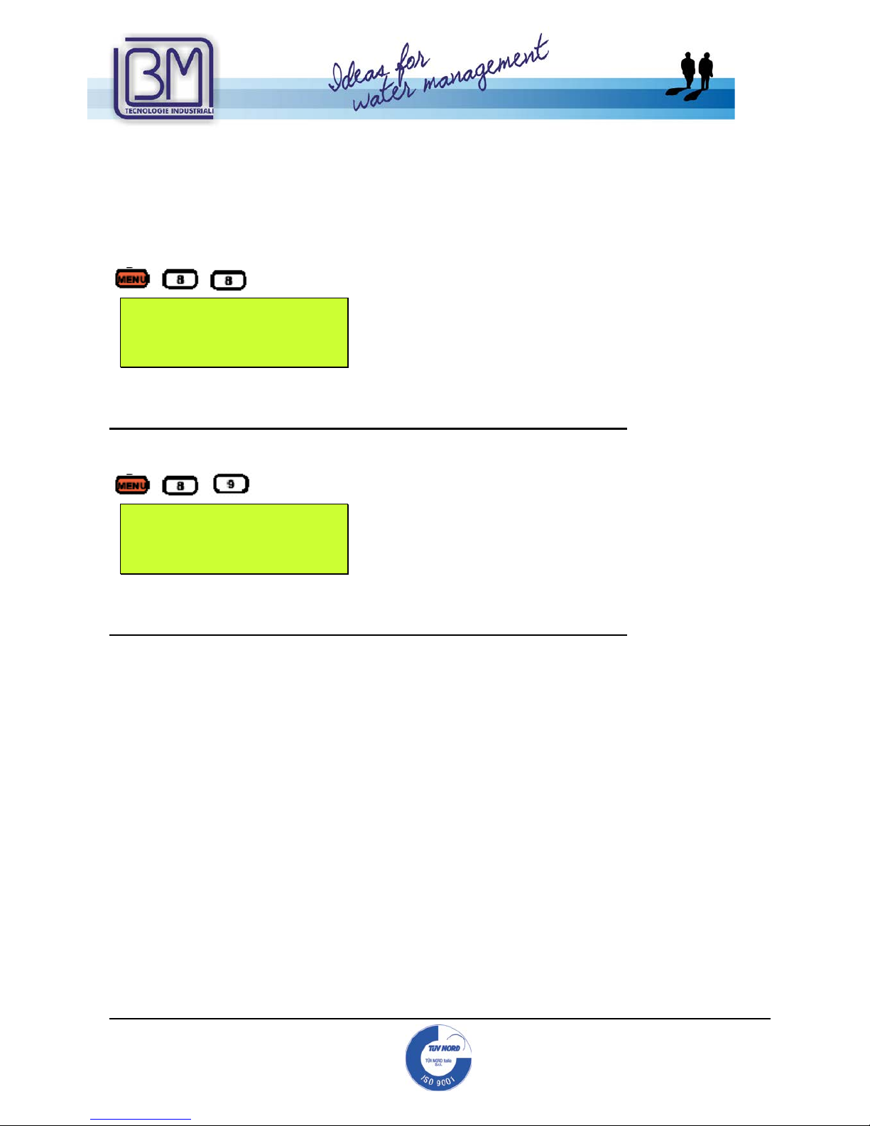
Digit
and the device will display
M85
Auto Power Off
Enable
Disable
This menu allows the user to enable or disable the automatic power off.
Select between the t wo options and press ENT to confirm.
WARNING!!!
THE FOLLOWING MENU 86, 87, 88, 89 ARE FOR EXPERT USERS
ONLY.
B.M. TECNOLOGIE INDUSTRIALI SUGGESTS NOT TO CHANGE THEM.
PLS LEAVE THE FOLLOWING MENUS AS DEFAULT SET.
Digit
and the device will display
M86
Auto CNTR Enable
YES
This menu allows the user to select between automatic or user defined status.
Automatic is the default status. User defined status is used to define peculiar
conditions in which the contro l parameters set by the customer are activated.
We suggest not to change this menu. Leave it as factory default.
If needed, select between the two optio n s and press ENT to confi rm.
Digit
and the device will display
M87
Power Selection
This menu allows the user to select how many p ulses wil l be sent out to activate the
transducers. The selection could be done among 1…10 pulses. Default setting: 10 pulses.
We suggest not to change this menu. Leave it as factory default.
If needed, select between the options and press ENT to confirm.
Mod.BM43
COM
Vers.1.0
16/11/2005
Page 60 of
95
B.M. Tecnologie Industriali
Via Praimbole 13
35010 LIMENA (PD)
VAT No. IT02459940280
Tel. +39 (0) 49 884.16.51
Fax +39 (0) 49 884.16.54
E-Mail bm@bmtecnologie.it
Web www.bmtecnologie.it
Menus M88 and M89 will be operative only if in menu M86, the user selected NO
(not default setting).
As we recommend not to change M86 settings, the following menus will not be
used.
Digit
and the device will display
M88
RCV Window Start
80
This menu allows the user to enter the sta r ting time of the receiving signal window.
Signals arriving before the starting time will be neglected by the device.
We suggest not to change this menu. Leave it as factory default.
If needed, select between the option s and press ENT to confirm.
Digit
and the device will display
M89
RCV Window End
125
This menu allows the user to enter the ending time of the receiving signal window. Signals
arriving after the ending time will be neglected by the device.
We suggest not to change this menu. Leave it as factory default.
If needed, select between the option s and press ENT to confirm.

Mod.BM43
COM
Vers.1.0
16/11/2005
Page 61 of
95
B.M. Tecnologie Industriali
Via Praimbole 13
35010 LIMENA (PD)
VAT No. IT02459940280
Tel. +39 (0) 49 884.16.51
Fax +39 (0) 49 884.16.54
E-Mail bm@bmtecnologie.it
Web www.bmtecnologie.it
3.12 DIAGNOSTICS MENU ANALYSIS
Digit
and the device will display
M90 0.0000%
Strenth+Quality
S=xxx, xxx Q=xx
Detect No Signal
This window displays the strength a nd the quality of the signal with numbers from 00.0 to
99.9.
00.0 means that there is no signal, 99.9 means that the signal is at its max. value.
In normal working conditions the streng th signal should be around 60.0.
During installation, quality and strength have to be at their max. values.
Digit
and the device will display
M91
TOM/TOS*100
100,25 %
This window displays the relationship between the transit time and the measured tim e. In
normal working conditions, it should be 100 +/- 3%. Bigger differences indicate an error in
mounting or the setting of wrong parameters.
Digit
and the device will display
M92
Fluid Sound Velocity
1482.56 m/s
This window displays the speed of sound through the fluid. In normal wor king conditions,
the value should be similar to the one indicated in menu M21. big difference indicate an
error during the sensors mounting or an error in the setting of M21.
Digit
and the device will display
M93
Total,Delta Time
623,80uS
242,12nS
This window displays the tota l transit time and the UP-DOWN difference between transit
times. The values give info r m ation about the installation. In normal working conditions the
difference is less than 10%.

Mod.BM43
COM
Vers.1.0
16/11/2005
Page 62 of
95
B.M. Tecnologie Industriali
Via Praimbole 13
35010 LIMENA (PD)
VAT No. IT02459940280
Tel. +39 (0) 49 884.16.51
Fax +39 (0) 49 884.16.54
E-Mail bm@bmtecnologie.it
Web www.bmtecnologie.it
If the pipe diameter is small or the fluid velocity is very low, the difference might be a little
bigger. If the difference, the flow rate and the speed are too big, they indicate a very bad
signal. The causes could be: pipe’s features, wrong mounting, wrong parameter setting.
Digit
and the device will display
M94
Reynold Number
12234.6 0.92435
This window displays the calculated Reynold’s number. It indicates the moving mode inside
the pipe.
Menus from M95 to M99 are not used. They will be implemented in the next
software versions.
3.13 OTHER DISPLAYS MENU ANALYSIS
Digit
and the device will display
M+0
ON/OFF Time
ENT When Ready
It is possible to see the last time the device has been switched ON/OFF.
Press ENT and then use the arrow keys to di splay the sequence of 64 ev en ts (from 00 up
to 63) of switching on and switching off.
Press the ↓ key to display:
M+1
Total Work Hours
35:34:45
Press the ↓ key to display:
M+2
Last Power Off Time
Date 06-08-12
Time 09:34:26
Press the ↓ key to display:
M+3
Last Flow Rate
0 m3/h
Press the ↓ key to display:
MENU
9
5

Mod.BM43
COM
Vers.1.0
16/11/2005
Page 63 of
95
B.M. Tecnologie Industriali
Via Praimbole 13
35010 LIMENA (PD)
VAT No. IT02459940280
Tel. +39 (0) 49 884.16.51
Fax +39 (0) 49 884.16.54
E-Mail bm@bmtecnologie.it
Web www.bmtecnologie.it
M+4
ON/OFF Times
132
Press the ↓ key to display:
Calculator
Input X=
0
It is used as a calculator, setting X value, and then Y value. Press ENT to calculate.
Press the ↓ key to display:
M+6
Velocity Change
1 m/s
The set up value is used as a threshold to genera te an alarm on the relay or on they OCT
when it has been pa ssed.
Press the ↓ key to display:
M+7
Protocol Select
0.Protocol 0(*Adxx)
This function is used to connect the R S232 port to a peculiar device.
Press the ↓ key to display:
RCV
SHP___________
This window displays the signal received f rom the sensors:
GOOD SIGNAL BAD SIGNAL

Mod.BM43
COM
Vers.1.0
16/11/2005
Page 64 of
95
B.M. Tecnologie Industriali
Via Praimbole 13
35010 LIMENA (PD)
VAT No. IT02459940280
Tel. +39 (0) 49 884.16.51
Fax +39 (0) 49 884.16.54
E-Mail bm@bmtecnologie.it
Web www.bmtecnologie.it
4. DIAGNOSTICS AND PROBLEM SOLVING
The TTFM100B-HH-NG series has a complete series of diagnostic s functions: it has a
continuous searching for errors or bad working conditions. The continuous displaying of
errors helps the customer identifying damages or unacceptable working conditions.
Displayed errors could happened:
- When switching on the device, during the initial test.
- During functioning, with error codes.
Causes and solutions are indicated in the below following tabl e:
4.1 AUTOTEST DURING SWITCHING ON AND POSSIBLE SOLUTIONS
ERROR
DESCRIPTION
SOLUTIONS
ROM PARITY ERROR Contact B.M. Tecnologie Industriali.
STORED DATA
ERROR
Digit ENT again during the initial set up.
TIMER SLOW ERROR
TIMER FAST ERROR
Switch off and then switch on. If the problem persists, contact
B.M. Tecnologie Industriali.
DATE TIME ERROR Set again date and time in menu M61.
4.2 ERROR CODES, CAUSES AND SOLUTIONS DURING FUNCTIONING
ERROR
CODE
INFORMATION IN
M08 WINDOW
CAUSES
SOLUTIONS
*R
Normal system
Regular functioning
*J
Sub CPU wrong
Damage in sub CPU
Contact B.M.
Tecnologie
Industriali.
*I
No signal detected
No signal detected:
- sensor far fro the
pipe or not so
couplant
- wrong sensors
mounting
- too many oxide or
dump inside the pipe
- new linearity
- check the acoustic
contact with the
pipe’s surface.
- use another
couplant
- check initial
settings
- try to reduce the
pipe’s internal
dumps or change
the sensors positio n
- wait for stable
linearity.

Mod.BM43
COM
Vers.1.0
16/11/2005
Page 65 of
95
B.M. Tecnologie Industriali
Via Praimbole 13
35010 LIMENA (PD)
VAT No. IT02459940280
Tel. +39 (0) 49 884.16.51
Fax +39 (0) 49 884.16.54
E-Mail bm@bmtecnologie.it
Web www.bmtecnologie.it
*H Low strength signal Low signal strength SEE ABOVE
*H Poor quality signal Poor signal quality SEE ABOVE
*F System RAM error
Date Time error CPU
or IRQ error ROM
parity error
Temporary RAM or RTC problem.
Permanent Hardware problems.
Switch off and then
switch on or contact
B.M. Tecnologie
Industriali.
*K
Empty Pipe
Wrong settings in M29
Replace the sensors
where the pipe is
full. Set “0” in M29.
4.3 OTHER PROBLEMS AND SOLUTIONS
a. If the flow is not static and t he device displays a flow rate of 0.0000, the code “R”,
and signal strength and quality are satisfying, the problem could have been caused
by the user who set a high “zero” value.
Solution: reset the device using M42 function. It will restore the factory settings.
b. The device displays a flow rate which is much higher or much lower than what
usually displayed in normal wor king conditions.
- Probably there is a problem with the OFFSET value. Set “0” in M44.
- Wrong transducers mounting.
- Reset the device by using M41 function. C hec k that the flow is completely
static.
c. The battery works for a short period. Shorter than what stated in M07.
- Replace the battery: it is over.
- Contact B.M. Tecnologie Industriali.

Mod.BM43
COM
Vers.1.0
16/11/2005
Page 66 of
95
B.M. Tecnologie Industriali
Via Praimbole 13
35010 LIMENA (PD)
VAT No. IT02459940280
Tel. +39 (0) 49 884.16.51
Fax +39 (0) 49 884.16.54
E-Mail bm@bmtecnologie.it
Web www.bmtecnologie.it
5. COMMUNICATION WITH A PC AND/ OR DATA LOGGING
This chapter informs the user about t he hardware connections to be done to allow a
communication between the device and the pc.
5.1 REQUIRED HARDWA RE
It is possible to connect a notebook to the device by using the serial port RS232-C: in this
way it will be possible to download data or send sign als to the TTFM100 ser i es.
Use a serial cable with a female DB9 connector on both sides. It is possible to buy the
cable in almost every electronic shops, it is a very common cable.
If you want, you could also made it by yourselves, please follow the instructions:
9 POLES FEMALE 9 POLE FEMALE
CONNECTOR CONNECTOR
5.2 COMPLETE PIN-OUT OF DB9 M DOOR
PIN CONNECTION TO…
1 Battery charger Positive pole input (+)
2 RXD- Received data
3 TXD- Sent data
4 Not Used
5 GND- Back signals
6 OCT Output- Positive Pole output (+)
7 Not Used
8 Battery charger Negative pole input (-)
9 RING input for MODEM connection

Mod.BM43
COM
Vers.1.0
16/11/2005
Page 67 of
95
B.M. Tecnologie Industriali
Via Praimbole 13
35010 LIMENA (PD)
VAT No. IT02459940280
Tel. +39 (0) 49 884.16.51
Fax +39 (0) 49 884.16.54
E-Mail bm@bmtecnologie.it
Web www.bmtecnologie.it
5.3 DIRECT CONTROL- COMMUNICATION PROTOCOL
CONTROL
FUNCTION
DQD (CR) DAILY FLOW RATE
DQH(CR) HOUR FLOW RATE
DQM(CR) MINUTE FLOW RATE
DQS(CR) SECOND FLOW RATE
DV(CR)
FLOW RATE SPEED
DI+(CR)
POSITIVE TOTALIZE R
DI-(CR)
NEGATIVE TOTALIZER
DIN(CR)
NET TOTALIZER
DID(CR)
ID NUMBER
DL(CR)
SIGNAL STRENGTH & QUALITY
DT(CR)
CURRENT DATE AND TIME
M@(CR)***
VALUE OF PRESSED KEY
LCD (CR)
DISPLAY CONTENT
FOdddd (CR)
OUTPUT FREQUENCE OF ddddHz VALUE
ESN (CR)
ESN DEVICE NUMBER
RING (CR)
MODEM COMMUNICATION MANAGING
OK (CR)
MODEM RESPONSE
GA
CONTROL FOR MESSAGES TO A GSM
GB
CONTROL FOR MESSAGES TO A GSM
GC
CONTROL FOR MESSAGES TO A GSM
DUMP (CR)
BUFFER CONTENT
DUMP0 (CR)
CLEANING OF BUFFER CONTENT
DUMP1 (CR)
COMPLETE BUFFER CONTENT
PREFIX BEFORE NETWORK ID NUMBER.
N
PREFIX BEFORE NETWORK ID NUMBER.
P
PREFIX BEFORE EACH CONTROL
&
CONNECTOR USED TO LOAD UP TO 6
CONTROLS.
(CR)= CHANGE OF LINE
“d”= DIGIT BETWEEN 0…9
@= KEY VALUE.

Mod.BM43
COM
Vers.1.0
16/11/2005
Page 68 of
95
B.M. Tecnologie Industriali
Via Praimbole 13
35010 LIMENA (PD)
VAT No. IT02459940280
Tel. +39 (0) 49 884.16.51
Fax +39 (0) 49 884.16.54
E-Mail bm@bmtecnologie.it
Web www.bmtecnologie.it
5.4 USE OF THE PREFIX IN THE CONTROL
a. PREFIX P: The P prefix is added before starting a control indicated in the
above mentioned list, in order to obtain a 2 byte control on the CRC code.
Example: control DI+ (CR). The d evic e r ep l ies w ith a value of
+1234567E+m3(CR)(LF), the converted hexadec im al line is 2BH, 31H, 32H, 33H,
34H, 35H, 36H, 37H, 45H, 2BH, 30H, 6DH, 33H, 20H, ODH, 0AH.
The same control with prefix P will be PDI+(CR), the device will repl y giving a value
of +1234567E+m3!F7(CR)(LF). “!” acts as a control start for summing the line
values, 2BH, 31H, 32H, 33H, 34H, 35H, 36H, 37H, 45H, 2BH, 30H, 6DH, 33H, 20H.
Before “!” there will be som free spaces (20H).
PREFIX W: it is used to control a net of devices for addressing the control’s
receiver device. Synthax composed of: IDN + base control.
It is possibile to use various ID between 0 and 65534, but 13 (0DH), 10
(0AH), 42 (2AH,*),38 (26H,&).
Example: if IDN is 12345 and you want to calcolate the speed value of the
addressed device, the control to be used will be W12345DV(CR).
b. PREFIX N: it not used anymore in t he new versions of TTFM100B.
c. CONNECTION CONTROL &: the & control permits to establish a
connection up to 6 simple controls in order to speed up a devices
questionnaire.
Example: we are asking to a device connected to a net with IDN=1234, the
following information: Flow rate, Speed and POs Totalizer.
The control will be: W1234DQD&DV&DI+(CR), the reply will be
+1.234567E+12m3/d(CR)
+3.123456E+00m/s(CR)
+1234567E+0m3(CR)
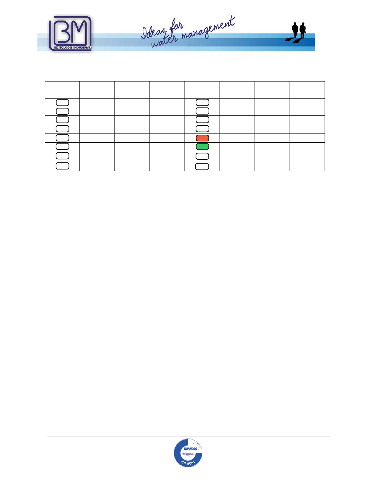
Mod.BM43
COM
Vers.1.0
16/11/2005
Page 69 of
95
B.M. Tecnologie Industriali
Via Praimbole 13
35010 LIMENA (PD)
VAT No. IT02459940280
Tel. +39 (0) 49 884.16.51
Fax +39 (0) 49 884.16.54
E-Mail bm@bmtecnologie.it
Web www.bmtecnologie.it
5.5 KEYPAD CODES
Key
HEX
Code
Key
Code
ASCII
Code
Key
HEX
Code
Key
Code
ASCII
Code
30H
48
0 38H
56
8 31H
49
1 39H
57
9
32H
50
2 3AH
58
:
33H 51 3
3BH,0BH 59 ;
34H
52
4
3CH,0CH
60
<
35H
53
5
3DH,0DH
61
=
36H 54 6
3EH 62 >
37H 55 7
3FH 63 ?
0
8
1
9
2
.
3
4
MENU
5
ENT
6
/+
7
/-

Mod.BM43
COM
Vers.1.0
16/11/2005
Page 70 of
95
B.M. Tecnologie Industriali
Via Praimbole 13
35010 LIMENA (PD)
VAT No. IT02459940280
Tel. +39 (0) 49 884.16.51
Fax +39 (0) 49 884.16.54
E-Mail bm@bmtecnologie.it
Web www.bmtecnologie.it
6. APPENDIX
6.1 SOUND SPEEDS IN SOLIDS

Mod.BM43
COM
Vers.1.0
16/11/2005
Page 71 of
95
B.M. Tecnologie Industriali
Via Praimbole 13
35010 LIMENA (PD)
VAT No. IT02459940280
Tel. +39 (0) 49 884.16.51
Fax +39 (0) 49 884.16.54
E-Mail bm@bmtecnologie.it
Web www.bmtecnologie.it

Mod.BM43
COM
Vers.1.0
16/11/2005
Page 72 of
95
B.M. Tecnologie Industriali
Via Praimbole 13
35010 LIMENA (PD)
VAT No. IT02459940280
Tel. +39 (0) 49 884.16.51
Fax +39 (0) 49 884.16.54
E-Mail bm@bmtecnologie.it
Web www.bmtecnologie.it
6.2 SOUND SPEEDS IN FLUIDS

Mod.BM43
COM
Vers.1.0
16/11/2005
Page 73 of
95
B.M. Tecnologie Industriali
Via Praimbole 13
35010 LIMENA (PD)
VAT No. IT02459940280
Tel. +39 (0) 49 884.16.51
Fax +39 (0) 49 884.16.54
E-Mail bm@bmtecnologie.it
Web www.bmtecnologie.it

Mod.BM43
COM
Vers.1.0
16/11/2005
Page 74 of
95
B.M. Tecnologie Industriali
Via Praimbole 13
35010 LIMENA (PD)
VAT No. IT02459940280
Tel. +39 (0) 49 884.16.51
Fax +39 (0) 49 884.16.54
E-Mail bm@bmtecnologie.it
Web www.bmtecnologie.it

Mod.BM43
COM
Vers.1.0
16/11/2005
Page 75 of
95
B.M. Tecnologie Industriali
Via Praimbole 13
35010 LIMENA (PD)
VAT No. IT02459940280
Tel. +39 (0) 49 884.16.51
Fax +39 (0) 49 884.16.54
E-Mail bm@bmtecnologie.it
Web www.bmtecnologie.it

Mod.BM43
COM
Vers.1.0
16/11/2005
Page 76 of
95
B.M. Tecnologie Industriali
Via Praimbole 13
35010 LIMENA (PD)
VAT No. IT02459940280
Tel. +39 (0) 49 884.16.51
Fax +39 (0) 49 884.16.54
E-Mail bm@bmtecnologie.it
Web www.bmtecnologie.it

Mod.BM43
COM
Vers.1.0
16/11/2005
Page 77 of
95
B.M. Tecnologie Industriali
Via Praimbole 13
35010 LIMENA (PD)
VAT No. IT02459940280
Tel. +39 (0) 49 884.16.51
Fax +39 (0) 49 884.16.54
E-Mail bm@bmtecnologie.it
Web www.bmtecnologie.it

Mod.BM43
COM
Vers.1.0
16/11/2005
Page 78 of
95
B.M. Tecnologie Industriali
Via Praimbole 13
35010 LIMENA (PD)
VAT No. IT02459940280
Tel. +39 (0) 49 884.16.51
Fax +39 (0) 49 884.16.54
E-Mail bm@bmtecnologie.it
Web www.bmtecnologie.it

Mod.BM43
COM
Vers.1.0
16/11/2005
Page 79 of
95
B.M. Tecnologie Industriali
Via Praimbole 13
35010 LIMENA (PD)
VAT No. IT02459940280
Tel. +39 (0) 49 884.16.51
Fax +39 (0) 49 884.16.54
E-Mail bm@bmtecnologie.it
Web www.bmtecnologie.it

Mod.BM43
COM
Vers.1.0
16/11/2005
Page 80 of
95
B.M. Tecnologie Industriali
Via Praimbole 13
35010 LIMENA (PD)
VAT No. IT02459940280
Tel. +39 (0) 49 884.16.51
Fax +39 (0) 49 884.16.54
E-Mail bm@bmtecnologie.it
Web www.bmtecnologie.it

Mod.BM43
COM
Vers.1.0
16/11/2005
Page 81 of
95
B.M. Tecnologie Industriali
Via Praimbole 13
35010 LIMENA (PD)
VAT No. IT02459940280
Tel. +39 (0) 49 884.16.51
Fax +39 (0) 49 884.16.54
E-Mail bm@bmtecnologie.it
Web www.bmtecnologie.it

Mod.BM43
COM
Vers.1.0
16/11/2005
Page 82 of
95
B.M. Tecnologie Industriali
Via Praimbole 13
35010 LIMENA (PD)
VAT No. IT02459940280
Tel. +39 (0) 49 884.16.51
Fax +39 (0) 49 884.16.54
E-Mail bm@bmtecnologie.it
Web www.bmtecnologie.it

Mod.BM43
COM
Vers.1.0
16/11/2005
Page 83 of
95
B.M. Tecnologie Industriali
Via Praimbole 13
35010 LIMENA (PD)
VAT No. IT02459940280
Tel. +39 (0) 49 884.16.51
Fax +39 (0) 49 884.16.54
E-Mail bm@bmtecnologie.it
Web www.bmtecnologie.it
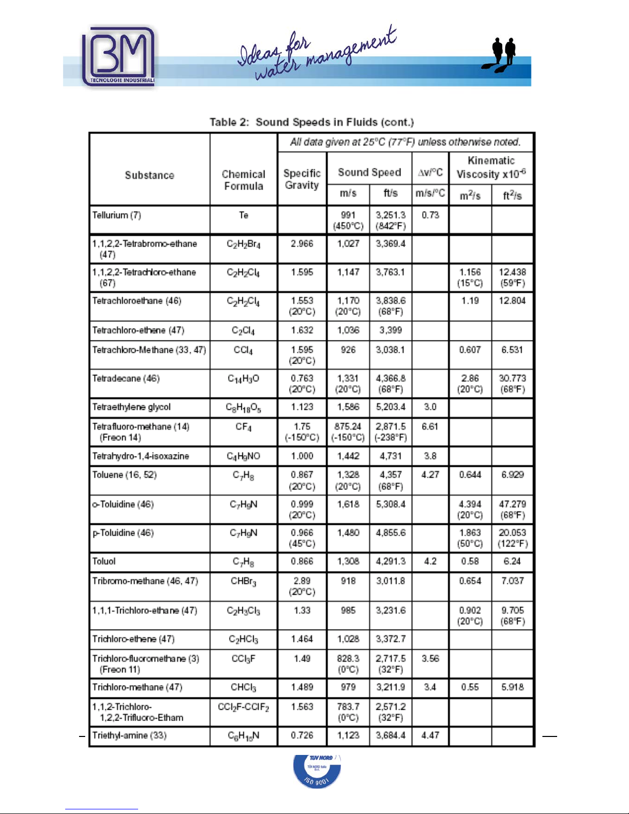
Mod.BM43
COM
Vers.1.0
16/11/2005
Page 84 of
95
B.M. Tecnologie Industriali
Via Praimbole 13
35010 LIMENA (PD)
VAT No. IT02459940280
Tel. +39 (0) 49 884.16.51
Fax +39 (0) 49 884.16.54
E-Mail bm@bmtecnologie.it
Web www.bmtecnologie.it

Mod.BM43
COM
Vers.1.0
16/11/2005
Page 85 of
95
B.M. Tecnologie Industriali
Via Praimbole 13
35010 LIMENA (PD)
VAT No. IT02459940280
Tel. +39 (0) 49 884.16.51
Fax +39 (0) 49 884.16.54
E-Mail bm@bmtecnologie.it
Web www.bmtecnologie.it

Mod.BM43
COM
Vers.1.0
16/11/2005
Page 86 of
95
B.M. Tecnologie Industriali
Via Praimbole 13
35010 LIMENA (PD)
VAT No. IT02459940280
Tel. +39 (0) 49 884.16.51
Fax +39 (0) 49 884.16.54
E-Mail bm@bmtecnologie.it
Web www.bmtecnologie.it
6.3 SOUND SPEEDS IN WATER AT SEL EC TED TEMPERATURES

Mod.BM43
COM
Vers.1.0
16/11/2005
Page 87 of
95
B.M. Tecnologie Industriali
Via Praimbole 13
35010 LIMENA (PD)
VAT No. IT02459940280
Tel. +39 (0) 49 884.16.51
Fax +39 (0) 49 884.16.54
E-Mail bm@bmtecnologie.it
Web www.bmtecnologie.it

Mod.BM43
COM
Vers.1.0
16/11/2005
Page 88 of
95
B.M. Tecnologie Industriali
Via Praimbole 13
35010 LIMENA (PD)
VAT No. IT02459940280
Tel. +39 (0) 49 884.16.51
Fax +39 (0) 49 884.16.54
E-Mail bm@bmtecnologie.it
Web www.bmtecnologie.it
6.4 PIPE SIZE DATA

Mod.BM43
COM
Vers.1.0
16/11/2005
Page 89 of
95
B.M. Tecnologie Industriali
Via Praimbole 13
35010 LIMENA (PD)
VAT No. IT02459940280
Tel. +39 (0) 49 884.16.51
Fax +39 (0) 49 884.16.54
E-Mail bm@bmtecnologie.it
Web www.bmtecnologie.it

Mod.BM43
COM
Vers.1.0
16/11/2005
Page 90 of
95
B.M. Tecnologie Industriali
Via Praimbole 13
35010 LIMENA (PD)
VAT No. IT02459940280
Tel. +39 (0) 49 884.16.51
Fax +39 (0) 49 884.16.54
E-Mail bm@bmtecnologie.it
Web www.bmtecnologie.it

Mod.BM43
COM
Vers.1.0
16/11/2005
Page 91 of
95
B.M. Tecnologie Industriali
Via Praimbole 13
35010 LIMENA (PD)
VAT No. IT02459940280
Tel. +39 (0) 49 884.16.51
Fax +39 (0) 49 884.16.54
E-Mail bm@bmtecnologie.it
Web www.bmtecnologie.it

Mod.BM43
COM
Vers.1.0
16/11/2005
Page 92 of
95
B.M. Tecnologie Industriali
Via Praimbole 13
35010 LIMENA (PD)
VAT No. IT02459940280
Tel. +39 (0) 49 884.16.51
Fax +39 (0) 49 884.16.54
E-Mail bm@bmtecnologie.it
Web www.bmtecnologie.it

Mod.BM43
COM
Vers.1.0
16/11/2005
Page 93 of
95
B.M. Tecnologie Industriali
Via Praimbole 13
35010 LIMENA (PD)
VAT No. IT02459940280
Tel. +39 (0) 49 884.16.51
Fax +39 (0) 49 884.16.54
E-Mail bm@bmtecnologie.it
Web www.bmtecnologie.it
7. EC- DECALARATION OF CONFORMITY

Mod.BM43
COM
Vers.1.0
16/11/2005
Page 94 of
95
B.M. Tecnologie Industriali
Via Praimbole 13
35010 LIMENA (PD)
VAT No. IT02459940280
Tel. +39 (0) 49 884.16.51
Fax +39 (0) 49 884.16.54
E-Mail bm@bmtecnologie.it
Web www.bmtecnologie.it

Mod.BM43
COM
Vers.1.0
16/11/2005
Page 95 of
95
B.M. Tecnologie Industriali
Via Praimbole 13
35010 LIMENA (PD)
VAT No. IT02459940280
Tel. +39 (0) 49 884.16.51
Fax +39 (0) 49 884.16.54
E-Mail bm@bmtecnologie.it
Web www.bmtecnologie.it
Because of B.M. Tecnologie Industriali policy of improving their products, the TTFM100
series, would be revised and improved.
Please inform us about misunderstandings or errors which You may find in this ma nual
comparing it to the device You bought.
Do not hesitate to contact us to suggest how to improve our devices, thank You.
B.M. TECNOLOGIE INDUSTRIALI s.r.l.
Via Praimbole, 13- 35010 LIMENA (PD)- ITALY
Tel. +39(0)49-8841651 – Fax +39(0)49-8841654
e-mail:
bm@bmtecnologie.it web: www.bmtecologie.it
 Loading...