

Page 1

BMS Inverted Biological
Microscope
74575
User Manual
This manual is written for BMS INVERTED BIOLOGICAL. For safety and for exerting
the best performance, making you familiar with the instrument entirely, it is strongly
recommended that you read this manual carefully before using the microscope. For the
further reference, please place this manual in a position where nearby the worktable and
fetched easily.
Page 2
Use Notices BMS INVERTED BIOLOGICAL
I、Safety Note
3
2
1、 Do not keep the instrument in a direct sunlight,
high temperature or humidity, dusty and easy
shaking environment. Make sure the stage is plane,
1
Figure 1
Figure 2
4
horizontal and stable enough.
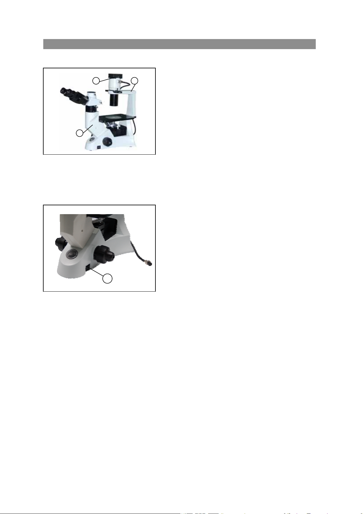
2、 When moving the microscope, please hold up the
instrument with one hand on the lower side of the
eyepiece tube ① , and the other hand on the
illumination bracket②.(figure1)
3、 If the bacterium solution or the water splash to the
stage, objective or viewing tube, pull out the power
cord at once, and wipe up the microscope.
Otherwise, the instrument will be damaged.
4、 When working, the lamp house on the top of the
arm③(figure1) will become very hot, be sure there
have enough room around the lamp house
(especially the top) for cool.
5、 Before replacing the lamp bulb or fuse, turn the
main switch on the “O”(off) position, then cut off
the power. If the lamp is on, or soon after it has
been turned off, it is hot and will cause serious
burns, please do the replacement after it cool down
completely.
★ Specified: the halogen lamp 6V/30W
6、 Earth this instrument to prevent the lightning strike.
7、 Use the supplied power cord, please.
Ⅱ、Maintenance
1、 Use the gauze to wipe the glass parts gently .If removing the fingerprints and oil stains , slightly
dampen gauze with the xylene or the admixture liquid which comparison is 3:7 of the ethanol and
the aether to wipe.
★ Note: the ethanol and the aether are all very combustible, do not put these chemicals near fire
or the possible electricity spark source such as the electronics equipments open ,close
operation . Use these chemicals in a well ventilated room as far as possible.
2、 Don’t use organic solvent to wipe the non-optical elements, If you need to clean, use the neutral
detergent, please.
3、 When using, if the microscope is splashed by liquid, cut off the power at once, and wipe up the
moisture.
4、 Do not disassemble any parts of the microscope. That will affect the function or decline the
performance of the microscope.
5、 If haven’t mounted the objective , please cover the dust cap to prevent the dust and the splashed
liquid of the tissue culture entering the inside.
6、 When not using, remember to cover up the microscope with the dust casing. And make sure the
Page 3

lamp cools down enough before you do so.
Ⅲ Safety Symbol
Symbol Meaning
The surface is very hot, not touch by your hands
Before using ,please read the instruction carefully, improper operation will result in bodily
injure or instruction malfunction.
The main switch on
The main switch off
Page 4
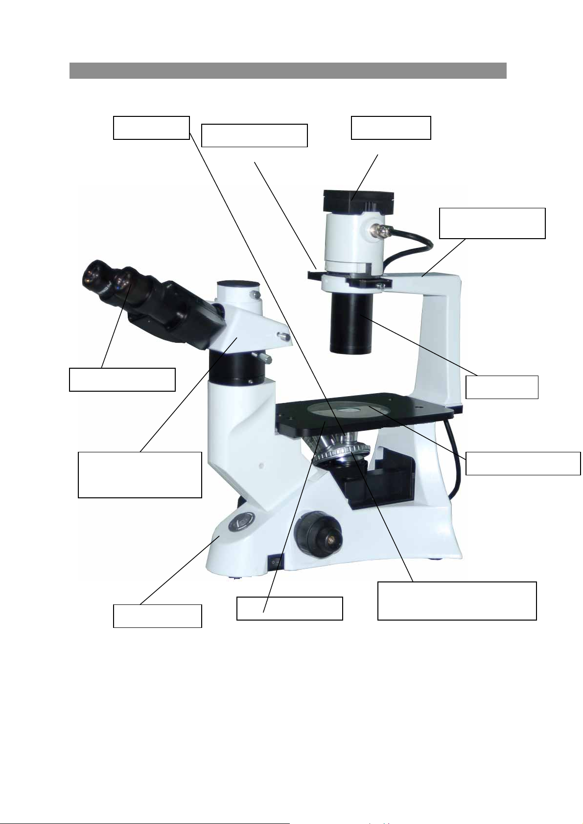
1. Components BMS INVERTED BIOLOGICAL
Ocular (eyepiece)
Trinocular viewing tube
(fixed)
Objective Lamp house
z 4X
z 10X(PH)
z 20X(PH)
z 40X
Phase contrast slider
Objective turret (Nosepiece)
Microscope base
Stage (fixed)
Quintuple
z Stage lengthen splint
z Glass stage
Figure 1
Illumination bracket
Condenser
Stage inserted plate
(fixed)
1
Page 5
2.Installation BMS INVERTED BIOLOGICAL
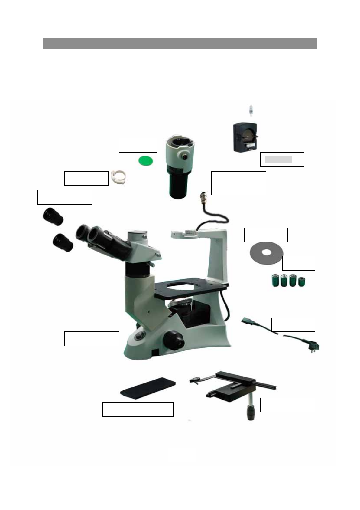
2.1 Installing diagram
The following figure shows the installation sequence of the components. The number in the figure
shows the installation steps.
Before installing, be sure every components is clean, do not score any parts or glass surface.
Keep well with the supplied hexagon wrench. When changing the components, you will need it
again.
Filter holder Condenser
Ocular(eyepiece)
Color filter
Lamp house
illumination unit
Glass stage
Objectiv
Power cord
Microscope base
Stage lengthen splint
Figure 2
Mechanical ruler
2
Page 6
BMS INVERTED BIOLOGICAL
2.2 Installing steps
4
Figure 3
3
1
5
4
6
2
Figure 4
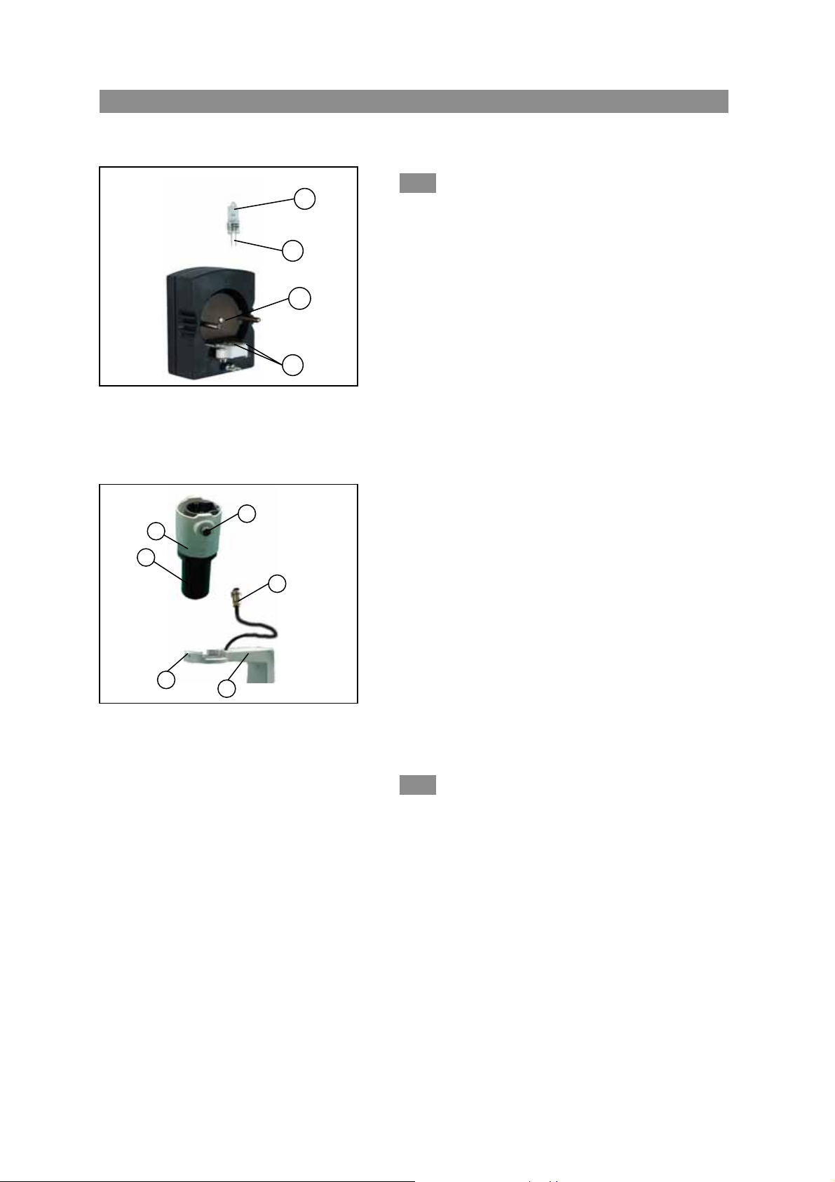
2-2-1 Installing and replacing the lamp
(figure3)
Please use the specified halogen Lamp 6V/30W.
1. Hold to the bulb ①after you wrap it with
gauze or other protection materials, then depress
the plugs 2 into the jack 3 on the lamp house,
ensure the filament and the bolt 4 are in a same
level.
2. Replacing the lamp when using or soon
after
When using, or soon after it is turned off, the
lamp, the lamp house and nearby parts will be
very hot and will cause serious burns. Please turn
the main switch on “O” (off), pull up power
plug, and make sure the bulb, the lamp house
and periphery are all cool. Then, you can do your
replacing.
Please insert the lamp gently, or it will be damaged
by excessive extrusion.
Do not touch the Halogen bulb with your hands.
It will shorten the service life or cause it to burst.
If you leave fingerprints on the surface carelessly,
clean it with a dry soft cloth.。
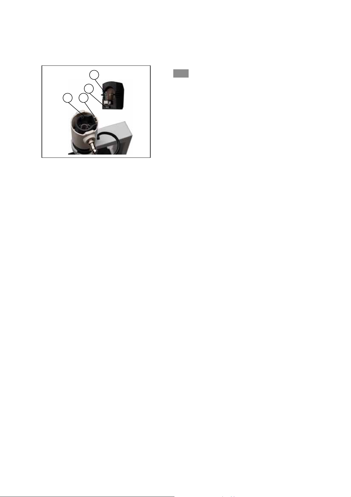
2-2-2 Installing the condenser illumination
unit(figure 4)
1. Insert the condenser illumination unit 1 into
the bracket 6 gently, according the figure showed
in the left.
2. Turn the condenser illumination unit at
clockwise about 90°, let the “AS” mark of filter
holder③ facing forwards, and keep the screw of
condenser illumination unit and the hole of the
holder in line, then screw down the bolt in the
hole with the supplied hexagon spanner.
Insert BNC connector plugs④ into BNC connector
Page 7
4
3
2
1
2-2-3 Installing the lamp house (figure 5)
Keep the BNC connector plugs① and the lamp
house pin② in line, and keep the bolt③ and the
condenser jack④ in line, too. Then push the
lamp house into the illumination unit gently
until they are against.
Figure 5
3
Page 8
BMS INVERTED BIOLOGICAL
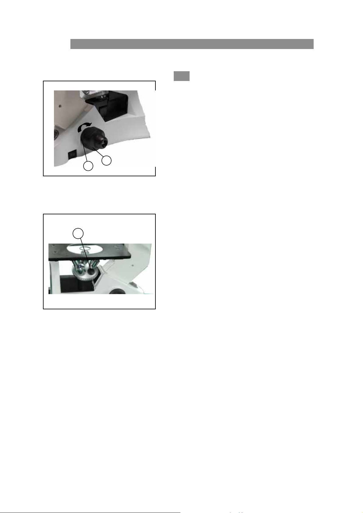
2-2-4 Installing the objective(Fig. 6 and
Fig.7)
1
2
1. Turning the coarse fusing knob① like the figure
shows till the nosepiece get to its lowest
position.
★For ensuring the safety of the
instruction on transportation, the nosepiece is
located in the lowest position and the tension
adjustment collar② is adjusted in a
appropriate tight tension while leaving the
Figure 6
3
factory.
2. Screw the lowest magnification objective on to
the turret from the nearside, then turn the turret
clockwise, mount other objectives according the
magnification sequence of low to high.
◎ Mount objective like this way will make the
change of magnification to be very easy in using.
◎ It also can install the objective through
the stage opening.
Figure 7
4
★ Clean the objective regularly, the objective used in
the inversed microscope is very sensitivity about
dust.
★ Do cover all the unused holes with turret dust
caps③, to prevent the dust and contamination
entering inside.
★ When operating, use the low magnification
objective (4X or 10X)to search and focus the
specimen at first, then replace the higher
magnifications if necessary.
★ When replace the objective, slowly turning the
nosepiece until you hear “clicked”, that means
the objective enter into the right position—center
of the light path.
Page 9
1
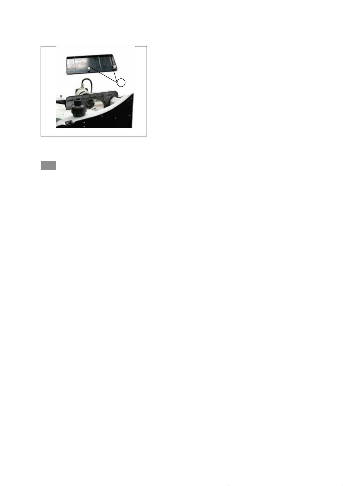
2-2-5
Installing the stage lengthen splint and the mechanical ruler(fig. 8)
Figure 8
5
◎ Stage lengthen splint can be installed in either side of the stage to enlarge the work surface. But you
can’t install the mechanical ruler together.
◎ Generally , the mechanical ruler will be installed in the right side for comfortable adjustment.
1. Installing the stage lengthen splint
First, Screw the fixed bolt① on to the splint , then mount it on to the stage from right or left below,
screwing down it until it stay hard.
2. Installing the mechanical ruler
Please install the ruler like the way of the stage splint.
Page 10
BMS INVERTED BIOLOGICAL
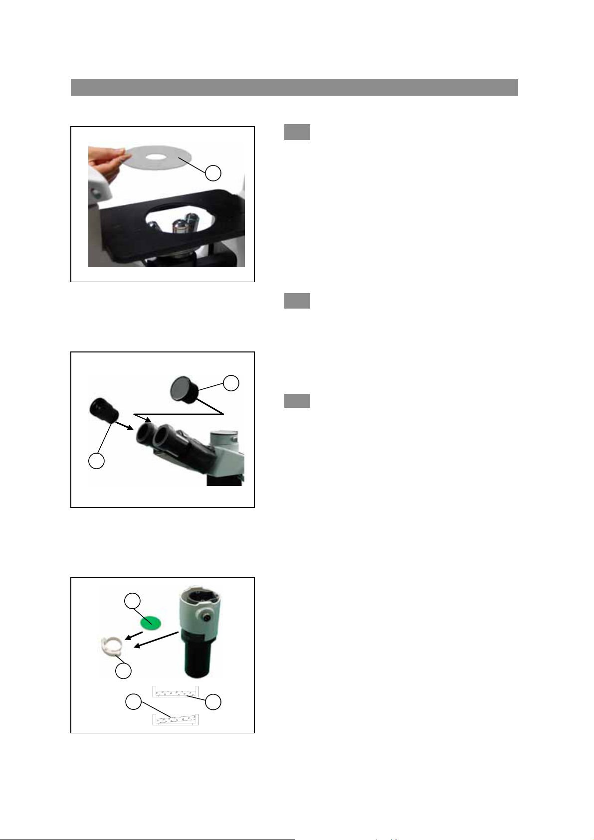
2-2-6 Installing the stage inserted plate(fig.9)
1
1. When using the glass stage ①, there is no special require,
you just need to place it in a plane.
2. Install the stage inserted plate on to the stage opening.
◎ Turn the disk, let the V nick to face user, so the recognition
of the objective will become easier.
Figure 9
1
2
2-2-7 Installing the eyepiece(fig.10)
1. Remove the cap of the eyepiece tube①.
2. Insert the eyepiece into tube until they are against.
2-2-8 Installing the color filters (fig. 11)
★ Be sure the color filter cools down completely before
you change them. Take down the filter holder①,
then install the color filters ②you need.
◎ Mount the color filter downwards like ③ shown, keep it
Figure 10
2
1
3
horizontal through the end, not allow inclined.
★ If the color filter is inclined or not get to the
end④, it will drop possibly.
◎The color filter could be piled on the holder, so you can
install more than one filter according the needs if you can
ensure the whole thickness is less than 11mm.
Figure 11
7
Page 11
BMS INVERTED BIOLOGICAL
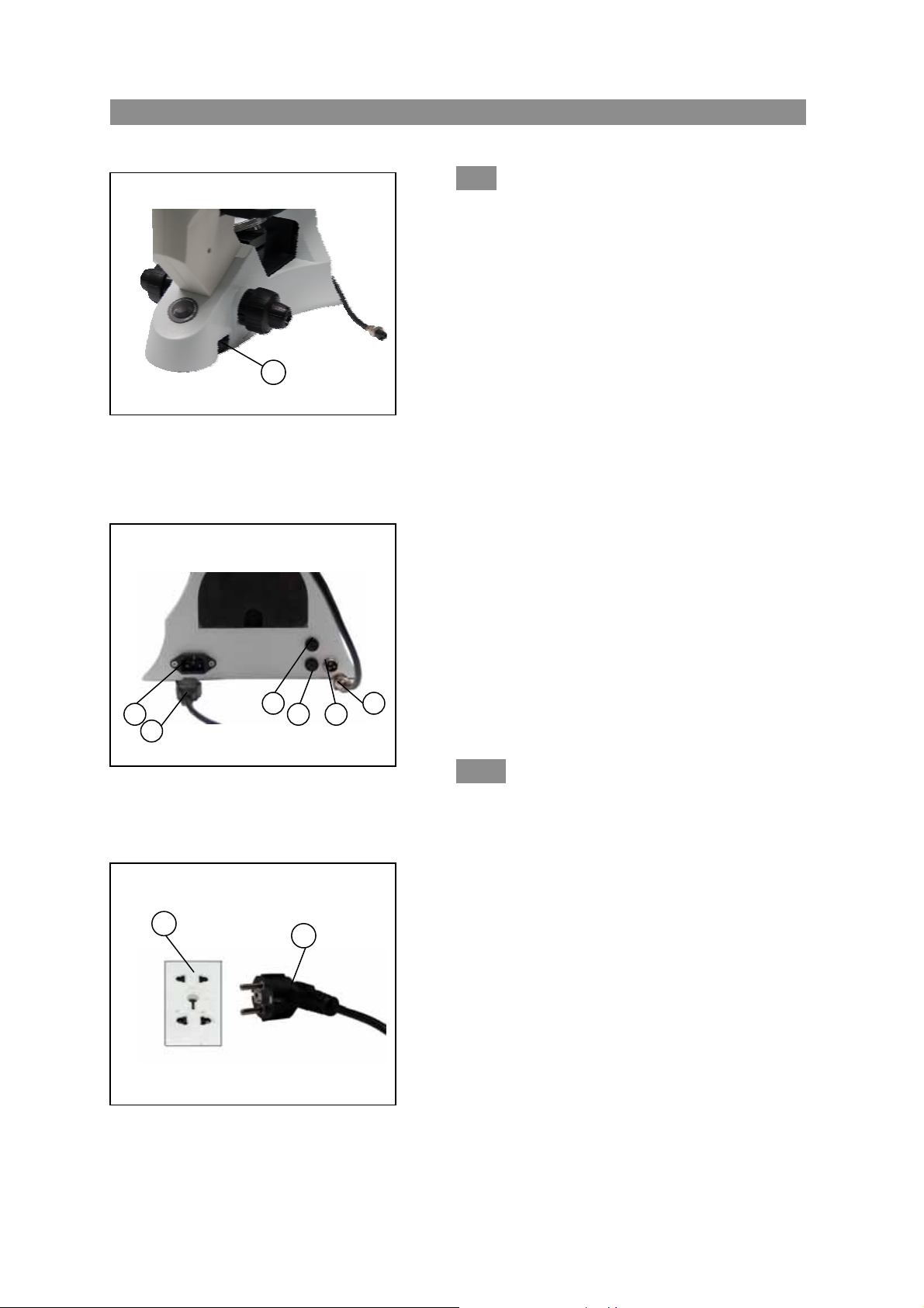
2-2-9 Connecting the power cord(fig.12、13
and 14)
1
figure12
★ Do not bring the power cord to bear a
powerful stress. When being bent or
wrapping, the cable and wires will be
broken easily.
1. Turn the main switch① on “O”(off) state
before connecting the power cord.
2. Insert the plugs② into the power jack ③of
the microscope safely.
3. Plug the power cord ④into the power supply
receptacle. Make sure the connection is
well.
4. Insert BNC connector plugs⑨ into BNC
connector jack⑧.
★ Do use the supplied power cord all the time.
If lost or damaged, select the same
standard cord, please.
★ Connect the power cord correctly, to ensure
the instrument is earthen.
2-2-10 Replacing the fuse(fig.12and 13)
Figure 13
5
4
Do remember to turn the main switch①
on the state of “O”(off) before replacing the
fuse, and unplug the power cord. Rotate the
fuse⑥ kits out of the holder⑦ by the
“--”type screwdriver, replace a new
fuse, then rotate back to the holder
again.
★ Fuse rating: 250V,500mA.
figure14
8
Page 12
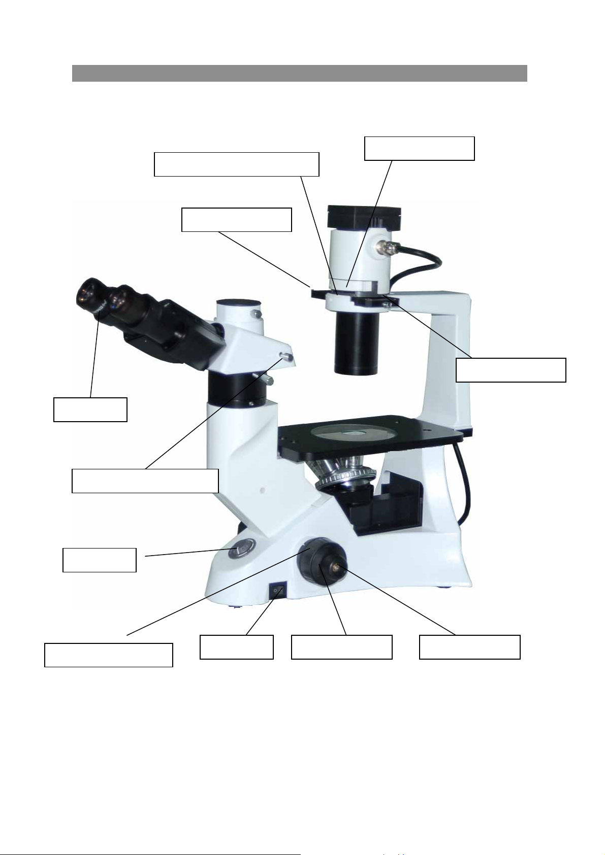
3. Adjustment BMS INVERTED BIOLOGICAL
Diopter ring
Light path selector lever
Light switch
Tension adjustment collar
Aperture diaphragm adjust lever
Phase center bolt
Main switch Coarse focus knob Fine focus knob
Figure 15
Color filter holder
Phase contrast slider
9
Page 13
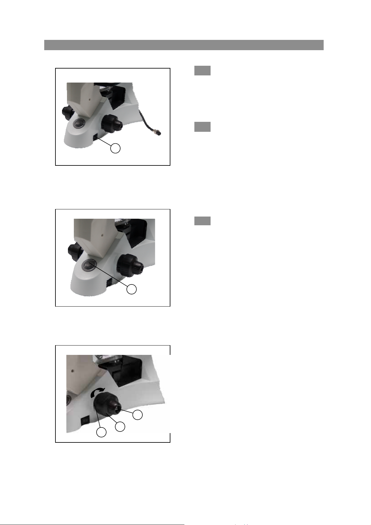
4. Operating the adjustment BMS INVERTED BIOLOGICAL
4-1 Microscope base
1
Figure 16
1
Figure 17
3
2
1
Figure 18
4-1-1 Turning on the lamp (fig.16)
Connect the power, turn on the main
switch①(shown on the fig.16)which on the bottom
side of the base to “-”(on).
4-1-2 Adjusting the brightness (fig.17)
Turning the brightness adjustment knob
clockwise, the voltage raise, and the brightness
strengthen; whereas turning at the contra direction,
the voltage decline, and the brightness weaken.
◎ Using the lamp in a low voltage
condition, will prolong the service life.
4-1-3 Adjusting the Tension Adjustment
Collar(fig.18)
★
The tight tension of the coarse focus knob ②had
already adjusted before leaving factory.
◎ How to adjust the tight tension
Turning the tension adjustment collar ①. while
revolving at the direction which shown by the
arrowhead on the figure, the tight tension of the coarse
focus knob② is increasing;and if at the contra
direction ,the tight tension will decline.
If the nosepiece dropped automatically, or the
specimen defocused soon even you focus with the
fine focus knob③. It means the coarse focus knob
is too loose, you should screw it down at the
direction shown by the arrowhead in the figure18.
10
Page 14
BMS INVERTED BIOLOGICAL
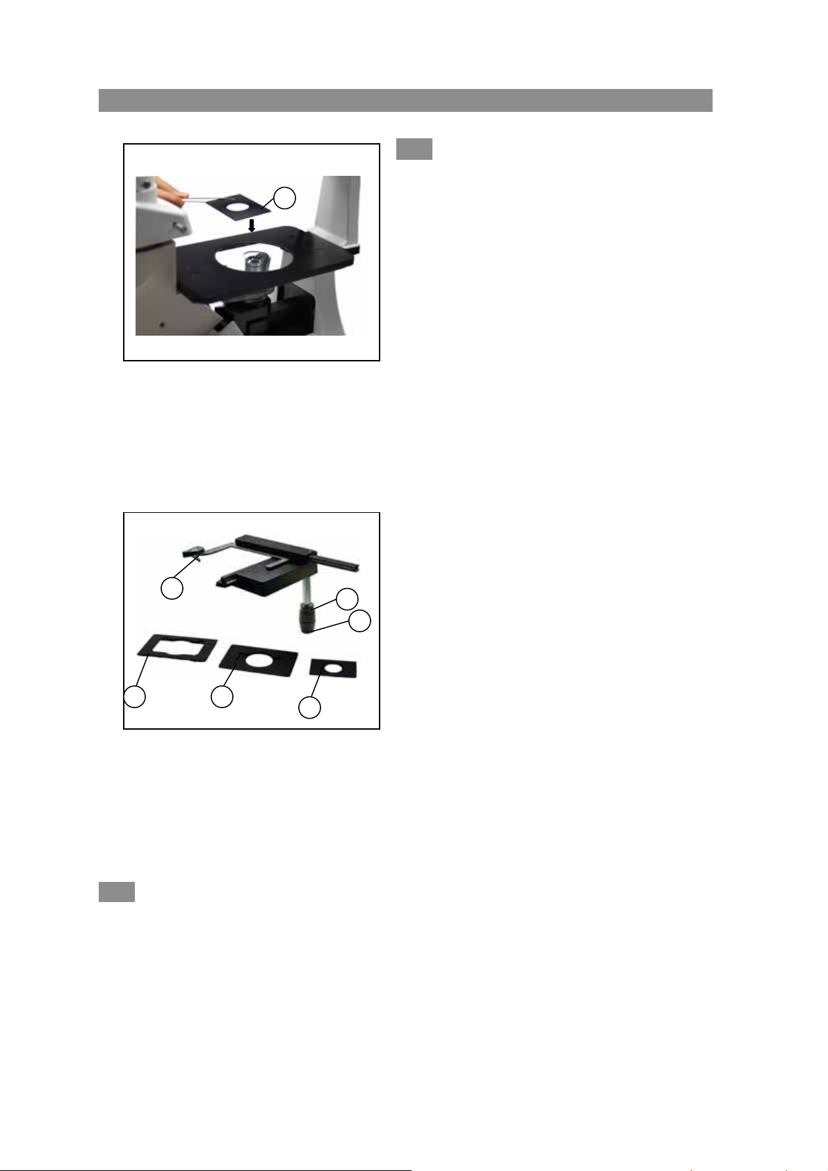
4-2 Stage
2
3
图 19
5
图 20
1
6
4
4-2-2 Moving the specimen
4-2-1 Setting the specimen(fig.19and fig.20)
Set the specimen in the center of the stage, please.
★
to obtain the best observe effect, please
select the containers, such as culture dish and
culture bottle, with the bottom thickness is
1.2mm, and the same thickness is also required
by the object slide when it is laid the specimen.
◎using the Φ35mm culture dish
You can lay aΦ35mm culture dish on the stage
directly by using the standard center board① of the
stage.
◎ using the mechanical ruler
1. When using the 96bit or 24bit micro-titration
board, please fasten it tightly by the stage
clips②.
2. When fastening other model boards, please use
the following supplied brackets with
mechanical ruler:
7
● Terasaki bracket③ for Terrasaki board
● Culture dish bracket④ for Φ 35mm
culture dish
● Object slide bracket⑤ for object slide
andΦ54mm culture dish
3. Turning the transverse knob ⑥and lengthways
knob⑦, move the specimen to the required
position. ( Movement Range: 120(width)×78
(Length)mm)
Turn the knob of the mechanical ruler or use your hands directly to move the specimen to the position
you wanted, please.
★ be careful when you replace the objective, please, especially after a short work distance
observation. Not let the objective to touch the stage inserted plate or the culture dish bracket.
11
Page 15
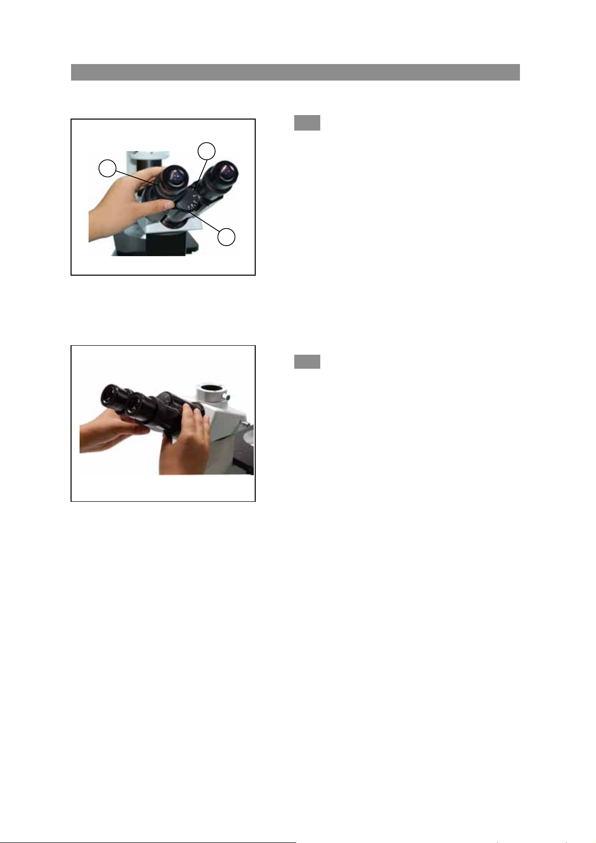
BMS INVERTED BIOLOGICAL
4-3 the viewing tube
Figure 21
Figure 22
2
3
4-3-1 Adjusting the diopter(fig.21)
1. Look into the right ocular by your right eye,
then revolving the coarse focus knob to focus
on the specimen.
2. Then use your left eye to look into the left
ocular. If the image is not sharp, just use the
diopter adjustment ring① to adjust please.
★ There are ±5 diopter in the adjustment
ring. The number which the reticle on the
eyepiece holder pointed is your eye’s diopter
graduation.
4-3-2 Adjusting the interpupillar distance
(fig.22)
When observing with two eyes, hold on the left
and right prism holder, turn around the axis,
adjusting the interpupillar distance until the left and
right fields of view coincide completely.
★ The reticle on the interpupillar distance
indicator③, pointed by the spot “.” ②on the
eyepiece holder, shows the scale of the
interpupillar distance.(fig.21)
The range of the interpupillar distance:
48~75mm。
12
Page 16
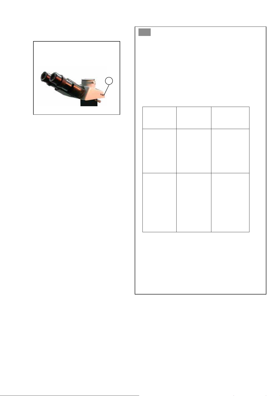
4-3-3 Switching the light path(fig.23)
◎ Pulling out the light path selector lever① by your
Figure 23
1
10
thumb, select the light path you needed.
◎ when in the binocular observation, pushing in the
lever until you heard a “clicked” .while in
video or photography, pulling out the lever until
it reached the “clicked” position.
Light path
selector
lever
Pushing in
the lever
until it
reached the
limit
position
Pulling out
the lever
until it
reached the
limit
position
Brightness
proportion
100% used for
binocular
observation
20% used for
binocular
observation,
and 80% used
for video or
photography
application
Binocular
observation
Binocular
observation,
television,
and
micrography
or video can
be operated
simultaneous
13
Page 17
BMS INVERTED BIOLOGICAL
4-4 Illumination Unit
1
2
Figure 24
Figure 25
70-80%
30-20%
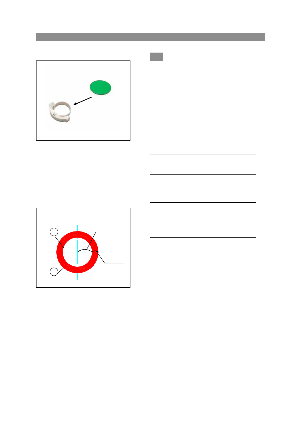
4-4-1 Using color filters(fig.24)
◎ Selecting the appropriate color filters
according your need, it became more
effective to observe or photography the
specimen. Especially, we suggest using
the LBD color filter, which can
compensate more neutral colors.
◎ You could pile up a group of color
filters to the filter holder, if you
ensure they are level and the whole
thickness is less than 11mm.
Color
filter
IF550
LBD
Single contrast color filter
(used for the phase contrast
Color temperature transit
color filter(blue)
(used for bright field
meaning
(green)
microscopy)
observation and
microphotography)
14
Page 18

4-4-2 using the aperture diaphragm(fig.25)
◎ When in the bright field observation, the aperture diaphragm control the numerical
aperture of the illumination system. Only when the numerical aperture of the objective
and the illumination system being matching, you can obtain the higher image resolution
and contrast, and the increased depth of field, too.
● To recognize the aperture diaphragm, you could remove the eyepiece if necessary. ( you
also could insert in the center telescope )then looked into the viewing tube, you might
see a field of view like the figure shown. The proportion could be changed by dialing
the aperture adjustment lever according your need. (①is the image of the aperture
diaphragm , ② is the edge of the objective)
● Generally, when observing the chromatic specimen, you need to set the size of the
condenser aperture diaphragm at 70%~80% of the numerical aperture which marked in the
objective. but if observing the bacterium specimen which not colored, you could turn
the aperture diaphragm lever at the direction of“
”(clockwise).
Page 19
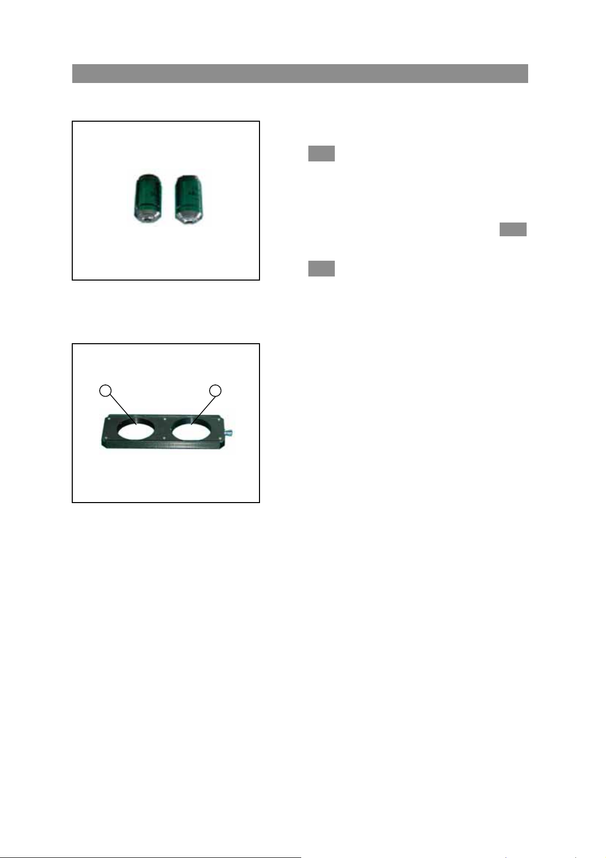
5.Phase contrast viewing BMS INVERTED BIOLOGICAL
5-1 The name of the components
Figure 26
1 2
5-1-1 Phase contrast objective(fig.26)
◎ the optional magnification of the
phase contrast is :10X、20X。
◎ If you want to know how to mount the phase
contrast objective, please see 2-2-4.
You ought to mount it on the turret.
5-1-2 Phase contrast slider(fig.27)
◎ phase centering adjustable slider
● The light ring was centered beforehand,
so it needn’t to adjust in the use
process. If the ring is not in the
center, you could adjust by the
centering bolt.
● The 10X/20X light ring ①is worked with
the 10X,20X phase contrast objective,
while the opening② is used for bright
field .
Figure 27
15
Page 20
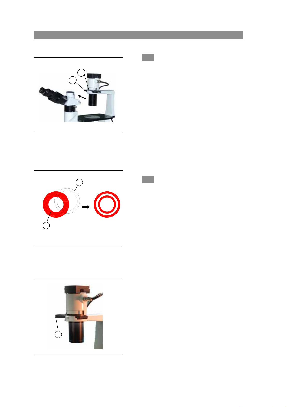
BMS INVERTED BIOLOGICAL
5-2 The installation and use
2
1
Figure 28
1
2
Figure 29
3
Figure 30
5-2-1 Installing the phase contrast
slider(fig.28)
1. Keep the slider① face ( the surface which had
character) up towards, then inserted it into the
illumination system from the right to the left
like the figure showed.
2. Every light ring or opening has its own
located position, so you need to move them
until you heard the “clicked” to ensure the ring
or the opening reaches the center of the light
path.
3. When in the phase contrast observation, do
keep the aperture diaphragm adjustment
lever② on the position of “O” (wide opening).
5-2-2 The centering ring(fig.29 and fig.30)
★ Usually you needn’t the operation of
centering. If necessary, please accord
to the following steps:
1. Place the specimen on the stage and
focus it.
2. Take out the eyepiece, replace it with
the CT ( the centering telescope),and
inserted it into the viewing tube
without diopter adjustment.
3. Make sure the matched phase contrast
objective and light ring( in the phase
contrast slider) have been in the center
of the light path.
16
Page 21

4. Using the CT to look the light ring’s image① and the phase contrast ring’s image②,
if the light ring’s image is not sharp, please shifting the CT’s ocular until you
can see a clear image of the light ring②.
5. Adjusting the bolts of the two centering holes③ in the phase contrast slider by the
screwdriver ③until the light ring center and the phase contrast center are coincided.
6. The 10X and the 20X phase contrast objective use the same light ring on the phase contrast
slider. So you need to check the coincidence of the light ring center and the phase
contrast center when changing the objective. If having departure, you ought to center
again.
★ If the light ring is centering incorrectly, you will fail to obtain the best viewing
effect of the microscopy.
★ After removing or replacing a thick specimen, the light ring and the phase contrast
ring are likely to deviate each other, which will result in a decline of the image
contrast. So if happened, please repeat the steps as above.
★ If the container or the cover flip which used to place the specimen is not flat, it
maybe need to repeat the centering steps for obtaining a more contrast effect. Please
center the light ring by the phase contrast objective, according to the sequence of
low to high magnification.
17
Page 22
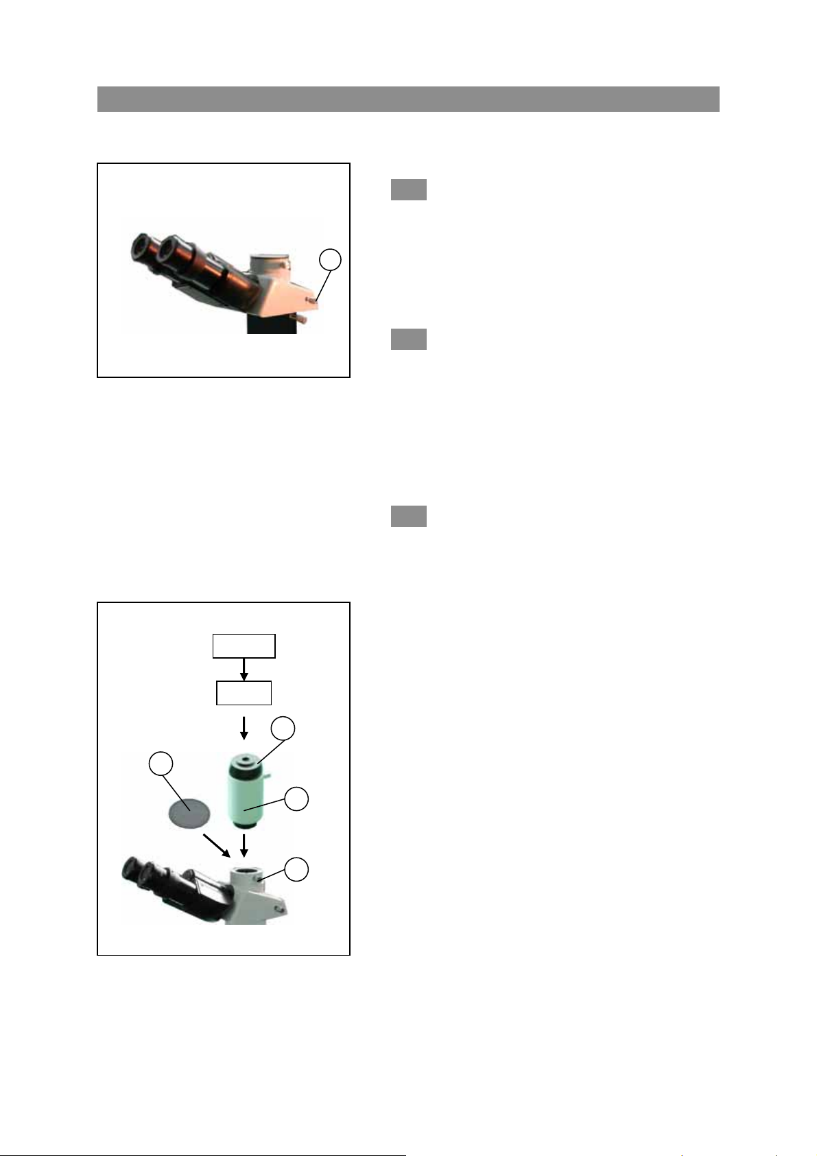
6.Microscope photography and video BMS INVERTED BIOLOGICAL
6-1 Microscope video
6-1-1 selecting the light path(fig.31)
1
Figure 31
★ just used in the trinocular observation
1. Pulling out the light path selector lever, until
you heard the “clicked”.
★ In the dark specimen observation, you can make
the focus by both eyes at first, then change the
light path.
6-1-2 Installing the video set(fig.32)
1. Loosen the locking bolt① on the trinocular
viewing tube, and take out the dust cap②.
2. Remove the dust cover on the both ends of the
video accessories③, and revolve the screw
head end into the CCD/CMOS port.
3. Install the accessories into the tri-through port,
and screw down the bolt①.
6-1-3 Focus(fig.32)
Doing a binocular observation at 20%
brightness, look the image on the video
or the computer which connected with the
2
video
CCD
4
3
microscope video system when the image
is sharp. If it is not in focus, please
turning the revolving video connected
tube④ until the image is sharp enough.
1
32
18
Page 23
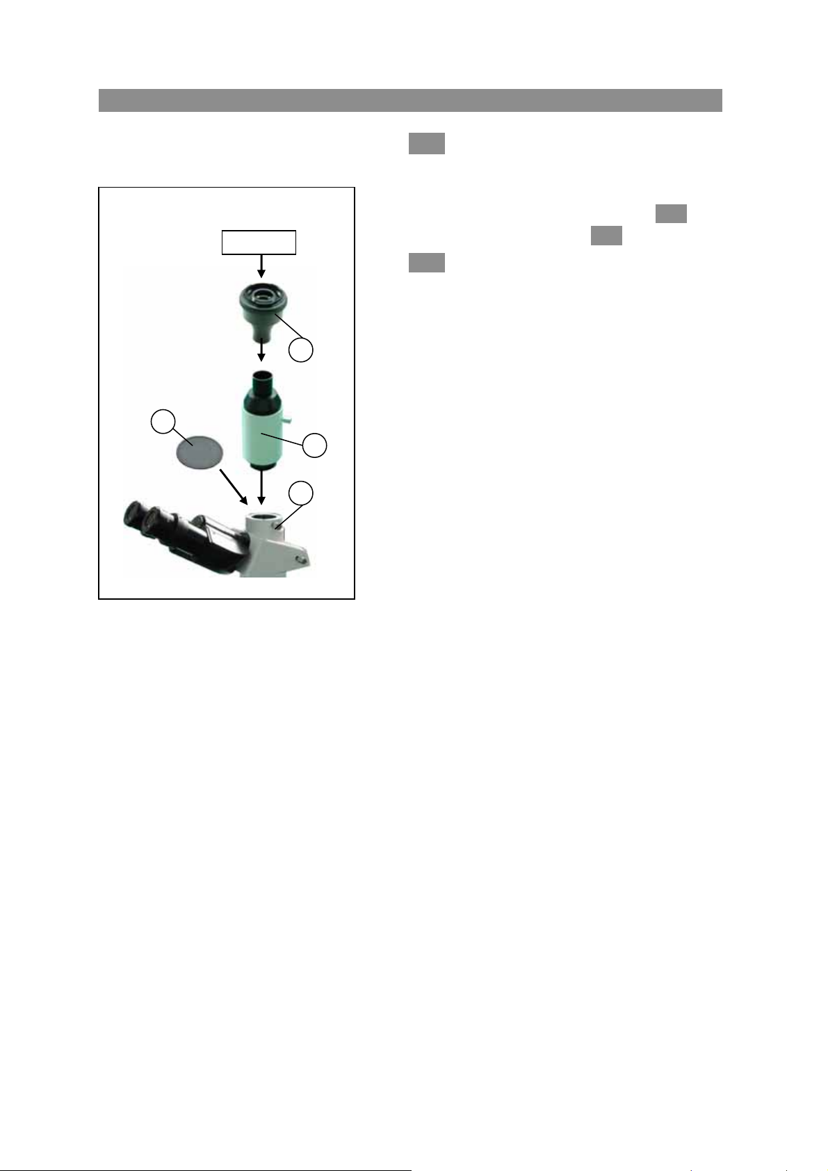
BMS INVERTED BIOLOGICAL
6-2 Microscope photography
2
camera
4
33
6-2-1 selecting the light path
★ just used in the trinocular
observation
The operation diagram is shown in 6-1-1,
and the details reference is in 4-3-4。
6-2-2 Installing the photography set
(fig.33)
1. Loosen the locking bolt① on the trinocular
viewing tube, and take out the dust cap②.
2. Install the photography accessories③ into the
tri-through port, and screw down the locking
bolts①.
3
1
3. Inserted the camera gate which on the digital
photography connected head④ into the
correspond position of the camera set port,
and screw it down clockwise.
5. Plug the digital photo connected head into
the photo tube, then screw down the locking
bolts①.
● Before connecting the camera and adapter,
remove the camera lens firstly, then connect
the lens port with the adapter. Pay attention
to the gate type, please.
● To avoid the disturbing from the ocular in the
observation, please place the viewer finder
on the two sides of the microscope when
installing the camera set.
● The camera magnification = objective
magnification ×camera lens magnification
★ When shooting the micrograph, the lens
close will bring an impact in some
camera. In order to weaken the impact,
and obtain a clear image, you could select
a longer time of exposure or decrease the
brightness to have some compensation.
★ This explanation is used for NiKon
Single-lens reflex digital camera
19
Page 24

6-2-3 Focus
Do the binocular observation at 20% brightness, and focus primary. When in microscope
photography, do use the camera viewfinder to focus the specimen. Please refer the user
manual of the camera set to obtain the details.
6-2-4 Adjusting the color temperature
◎ When shooting the chromophotograph, please use the sunlight film.
1. Mount the LBD temperature changed color filter on to the color filter bracket.
2. Turn the brightness adjustment knob to the maximal position, so you obtain a sunlight
illumination.
20
Page 25

7.Technical specifications BMS INVERTED BIOLOGICAL
7-1 Main specifications
Optical
system
Viewing Tube
Eyepiece Wide Field Eyepiece 10X, Linear Visual Field: 22 mm
Nosepiece Backward Quintuple Nosepiece
Objective
Focusing
System
Stage
Mechanical
ruler
Illumination Halogen Lamp 6V30W, Preset Center, Intensity continued Adjustable
Condenser Long working Distance Condenser, Numerical Aperture 0.3, Working Distance 72mm
Operation
environment
Infinite Optical System
Compensation Free Trinocular Tube Inclined at 30;
Division ratio: 20% of Binocular Viewing and 80% of Video Viewing & Micrography
Infinite Long Working Distance Plan Achromatic: 4X、40X
Infinite Long Working Distance Plan Phase Contrast: 10X、20X
Coaxial Coarse and Fine Focusing System
Sensitivity and Graduation of Fine Focus: 0.002mm
Movement Range(from the surface focus of stage plate): up 8mm, down 3mm
Area: 160(width)×250(Length)mm
Movement Range: 120(width)×78(Length)mm
z Use indoor
z Altitude: Maximum 2000 m
z Temperature: 5℃~40℃(41°F~109°F)
z Maximum Relative Humidity: 80% at 31℃(88°F), then Fall Linear.
z 70% at 34℃(93°F), 60% at 37℃(104°F),50% at 40℃(104°F).
z Pollution Degree:2 (refer to IEC60664)
7-2Objective Specifications
TYPE
Infinite
Long
Work in g
Distance
Plan
Achromatic
Objective
Infinite
Long
Work in g
Distance
Plan Phase
Contrast
Objective
MAGNIFICATION
4X 0.1 25.2
40X 0.6 3.2
10X 0.25 11
20X
NUMERICAL
APERTURE
(N.A)
0.4
WORKING
DISTANCE
(mm)
6
CONJUGATE
DISTANCE
(mm)
∞
∞
∞
∞
FOCUS
DISTANCE
(mm)
45
45 1.2mm
45
45
COVER
SLIP
THICKNESS
─
0.17
0.17
21
Page 26

8.Trouble Shooting BMS INVERTED BIOLOGICAL
Under certain condition, some no-fault factors will bring a reversible influence to the instrument’s
performance. If the problem is happened, please take
you can’t solve the trouble by the supplied methods, please contact with the sales department of our
company.
proper measures according to the follow table. If
PROBLEM REASON
I、Optical Part:
1. The illumination
is opening, but the
field of view is dark.
2. The edge of the
field of view has
shadow or the
brightness is
asymmetry
3.
Find dust and
stain in the field
of view
4. appear double
image
5. Resolution
problems:
z Image is not
z The contrast is
z The detail is
z Don’t obtain
sharp;
not high;
not clear;
the phase
contrast effect
The plug of the lamp holder is
not connected into the
illumination set
The bulb burnt out Change a new lamp 3
The brightness is too low Adjust to a proper position 8
The color filter is piled too
much
No use the appointed lamp
bulb
The nosepiece is not in the
located position
the color filter is stopped
midway
The phase contrast slider is not
located in the proper position
There are stains on the
specimen
There are stains and dust
on the eyepiece
the size of the aperture
diaphragm is too small
The nosepiece is not in the
center of the light path
the aperture diaphragm in the
view of field is opened too
large or too small
The lens (condenser, objective,
ocular or culture dish)
become dirty
In the phase contrast
observation, the bottom
thickness of the culture dish is
more than 1.2mm.
Use a bright field objective Change to the phase contrast
SOLUTION
Connect them well 3
Minimize the number of the
filters
use the specified halogen Lamp
6V30W
Turn the nosepiece into the
position where you can hear
“clicked”
Insert deeply 5
Turn the slider into the
“clicked” position
Open up the aperture
diaphragm
ensure the nosepiece is turned
into the “clicked” position
adjust the aperture diaphragm
correctly
Clean all
Use a the culture dish whose
bottom thickness is less than
1.2mm
objective
Change a clean specimen
Clean the eyepiece
PAGE
11
13
11
11
12
3
4
4
9
22
Page 27

6.one side of the
image is unfocused
The condenser ring is not
coincident with the objective
phase ring
The light ring and the phase
contrast kits is not centered
The objective used is not fit
to the phase contrast
observation
When looking at the edge of
the culture dish, the phase
contrast ring and the light ring
is deviated each other
The nosepiece is not in the
center of the light path
The specimen don’t place
properly
The optical performance of the
culture dish bottom is poor
(such as erose figure and soon)
Adjust the condenser ring to
match the objective phase ring
12
Adjust the bolts to center them 12
Please use the compatible
objective
12
Moving the culture dish until
you obtain the phase contrast
effect. You also could demount
the slider, and dail the field
13
diaphragm with the direction of
“
”
Insure the nosepiece is in the
“clicked” position
Place the specimen on the
stage correctly.
4
9
Please use a regular culture
dish
23
Page 28

BMS INVERTED BIOLOGICAL
PROBLEM REASON
II、Mechanical Part:
1.The coarse focus
knob is hard to run
2.The image can’t stay on
the focal plane in the
process of the observation
III.Electric Part:
1 The lamp can’t
light
The bulb burns out
in a high frequency
1、 The height of
the brightness is
not enough
2、 The light
glimpse
Ⅳ. Viewing tube
The two eyes’ field
of view is different
Ⅴ. Microscope video
1.the image is
unfocused
There is faintness
around the image
3.The indoor window
or the fluorescence
lamp develop
The tension adjustment
collar is too tight
The tension adjustment
collar is too loose
No power supply
the installation of the bulb is wrong
The bulb burn out Change a new bulb
Not use the specified lamp Use the required lamp
Not use a appointed lamp use a appointed lamp
The brightness adjustment
knob is used wrong
The bulb is going to spoil Change the bulb
The power cord have a poor
contact
The interpupillar distance is
not correct
The diopter is not right Adjust the diopter 10
Not adapte to the microscope
observation
Focus incorrectly
It is a inherent character of the
achromatic objective
The extra light entered into the
eyepiece and viewfinder is
reflected
SOLUTION
Loose properly
Tighten properly
Check the power cord, and
connect them exactly
Install the bulb correctly
Adjust the brightness
adjustment knob in a correct way
Check the power cord, and
connect them exactly
Adjust the interpupillar
distance
When look into the objective, do
not stare at the specimen but at the
whole field of view, or move the
eyes away to see other things, then
back into the objective
Adjusting the focus system, make the double
reticle and the specimen distinctly to see
The problem is unavoidable if you
used an achromatic objective
Cover up the eyepiece and the
viewfinder of the microscope
illumination system
PAGE
8
8
6
3
3
3
3
8
3
6
10
10
24
 Loading...