

BMR Suspension XSB005 User Manual
ANTI-ROLL BAR INSTALLATION
Part # XSB005
Thank you for purchasing BMR products. Please take a moment to verify contents of this package before proceeding
with the installation. The second page contains a chart of all provided parts and hardware. It is the responsibility of the
Purchaser to inventory these contents before vehicle disassembly.
NOTE: While this installation can be performed on jack stands, a drive-on service lift is recommended.
1. To properly install this product, make sure the rear end is
centered in the chassis before proceeding. This can be done by
taking wheel position measurements. Once measurements are
taken, compare sides and adjust accordingly. An adjustable
panhard rod is necessary if the rear end is not centered at ride
height.
2. Lift vehicle and support with stands under the outermost areas
of the axle. The installation must be performed with the rear
end loaded. Remove both rear wheels and tires.
3. Remove the exhaust and exhaust hangers.
4. Remove the factory sway bar using a 15mm socket.
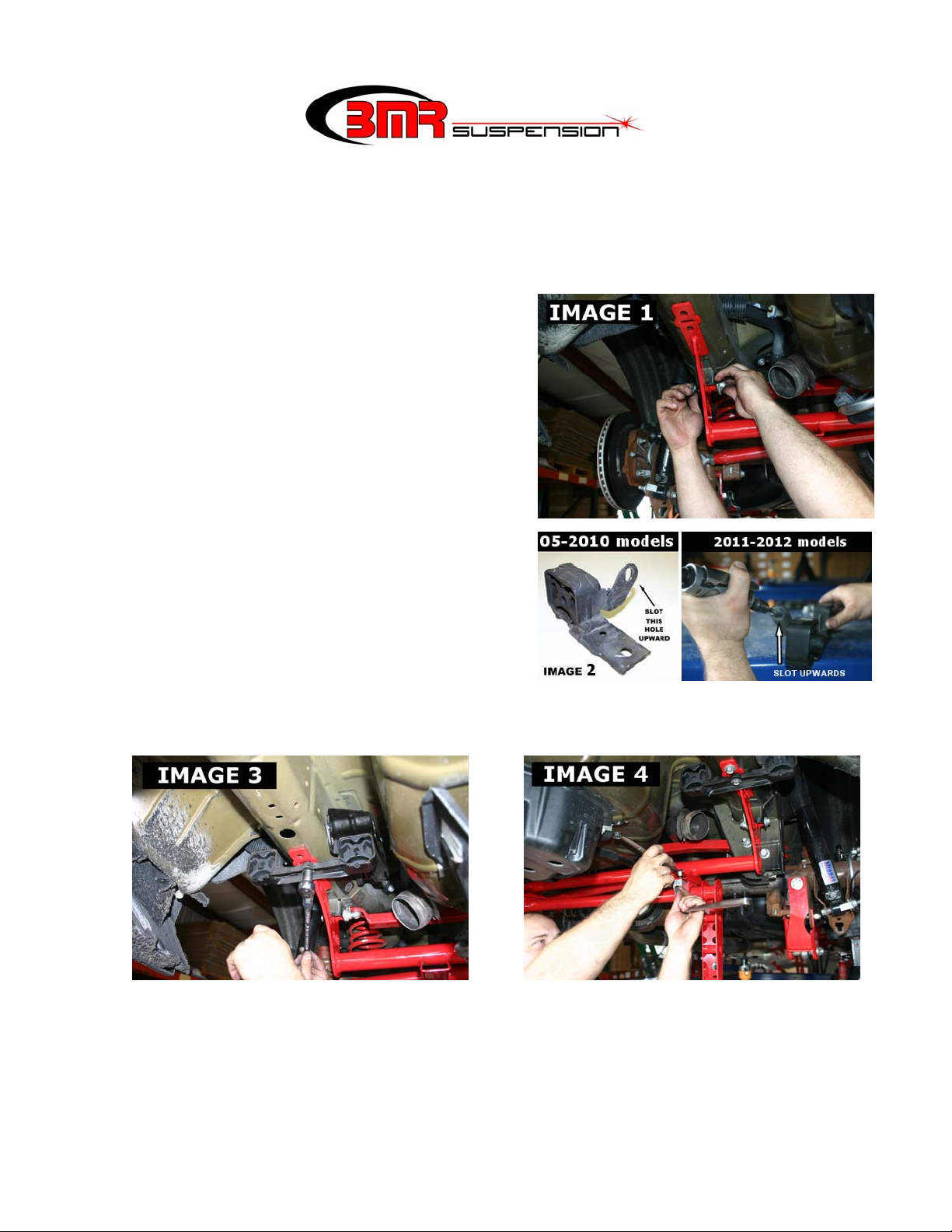
5. Install the BMR sway bar mount using the provided ½” x 2-
3/4” bolts. The mount uses the factory sway bar link mounts on
the frame and the muffler hanger mounts on the frame rails.
See Image 1.
6. If the vehicle still has the factory exhaust or uses the factory
exhaust hangers, it is necessary to modify the front muffler
hanger for re-installation. Remove the front hanger and slot the
mounting holes as shown in Image 2. The holes need to be
slotted upward approximately 3/16”, enough to allow the
BMR sway bar mounting bracket to fit underneath the muffler
bracket.
7. With the BMR sway bar mount suspended by the OE sway bar
mounts, re-install the modified muffler hangers using the
factory bolts. (Image 3)
8. Once the mount is installed and all bolts tightened, it is time to hang the sway bar. Slide the mounting bushings on
each end of the bar. Using the supplied 3/8” x 1” Allen bolts, nuts, and washers, mount the sway bar to the sway
bar mount as shown in Image 4 below. Tighten all four bolts with a 5/16” Allen wrench and 9/16”socket.
9. Bolt the end-link assemblies to the ends of the sway bar levers using either one of the mounting holes. Tighten
with a ¾” wrench and ¾” socket.
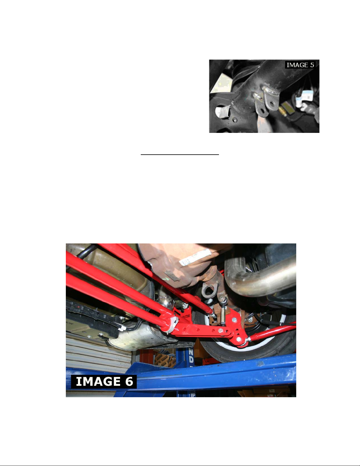
10. Bolt the axle tabs to the other end of the end links as shown in Image 5 on the next page. Rotate the sway bar
upwards until the tabs sit flush with the rear end housing. Verify that the tabs are as vertical as possible before tack
welding into place (Note: End links that are not vertical may fail due to binding of the spherical bearing when the
CONTINUED
ANTI-ROLL BAR INSTALLATION
Part # XSB005 (Continued)
axle articulates.). Once they have been tack welded, unbolt the tabs
and swing the sway bar down out of the way to gain weld access.
Weld tabs into place. Finished tabs should look similar to Image 6
below.
11. Re-install the end links. End-links should be made as short as
possible while still providing adjustment. Insert the supplied ½” x
2-3/4” bolts and tighten using a ¾” wrench and ¾” socket.
Tighten the jam-nuts on the end-links using two ¾” wrenches.
12. Double check all bolts to verify they are tight. Grease the
polyurethane bushings with a silicone based polyurethane lube.
13. Re-install both wheels and tires.
SWAYBAR SETUP
Because every vehicle is different there isn’t one ideal setup that will work for every application. Weight bias, tire
choice, driving style and horsepower will dictate which setting works best for you but as a general rule of thumb you
may follow the proceeding guidelines:
• Furthest hole from bar: This is the lightest setting and the recommended starting point for
most applications.
• Closest hole to bar: Use this setting if the car still wants to torque steer or will not leave
the line without excessive body roll.
It is also possible to fine tune your sway bar by pre-loading the end links. BMR recommends starting with a neutral
setup. This means that both sides are adjusted equally and no pre-load is in the bar. If the car tries to steer right on
launch, either lengthen the passenger side end link or shorten the drivers’ side end link to compensate. If it tries to steer
left at launch, shorten the passengers’ side end link or lengthen the drivers’ side to compensate.
WWW.BMRSUSPENSION.COM
This product is an aftermarket accessory and not designed by the vehicles manufacturer for use on this vehicle. As
such, Buyer assumes all risk of any damage caused to the vehicle or person during installation or use of this product.
 Loading...